
Beam current measurements on a Compact Isochonus...
58
Eindhoven University of Technology Department of Applied Physics Group Partiele Physics Supervisors: Beam current measurements on a Compact Isochonus Low Energy cyclotron Maarten Keuzenkamp Report of graduation work, november 1994 VDF /NK 94-41 prof. dr. ir. H.L. Ragedoorn dr. ir. J.A. van der Heide
Transcript of Beam current measurements on a Compact Isochonus...
Eindhoven University of Technology Department of Applied Physics Group Partiele Physics
Supervisors:
Beam current measurements on a Compact Isochonus Low Energy cyclotron
Maarten Keuzenkamp
Report of graduation work, november 1994 VDF /NK 94-41
prof. dr. ir. H.L. Ragedoorn dr. ir. J.A. van der Heide
Abstract
In this report the optimalisation of the extraction efficiency of the mini-cyclotron ILEC is described. This cyclotron is under construction at the Eindhoven University of technology. For the optimalisation of the extraction efficiency of this cyclotron the orbit center of the outer revolutions has been determined and the effect that the various correction coils can establish on this orbit center has been measured. From these measurements it became clear that the magnetic field of the cyclotron is containing an undesired magnetic distartion which was limiting the maximum extraction efficiency to approximately 15%. The effect of this magnetic distartion could not sufficiently he compensated by the various correction coils. Therefor the main magnetic field has been adjusted slightly. These adjustments resulted in an extraction efficiency of approximately 85%. Further increase was obtained by placing an aperture that interceptspart of the internal beam near the cyclotron center. This aperture also makes it possible to extract just one revolution, this is known as single turn extraction. The single turn extraction is required for a low energy spread.
11
Preface
In the beginning of the 1980's an increasing demand for accelerated ions was expected in the Partiele Physics Group of the department of Applied Physics of the Eindhoven University of Technology. Since in the group only one cyclotron was available, which had to be used for either analysis of materials, or for the production of radioactive nuclides for medical applications, a second cyclotron was designed. This cyclotron will be used for the application of micro-beam material analysis techniques. The ion beam needed for these experiments is characterized by a high optical quality. In the design of this cyclotron a flat-topping system was included tomeet the desired demands of the quality of the beam. In 1982 the actual construction of this cyclotron was started, and fora few years now, this cyclotron is capable of producing an external ion beam. In this period the ion beam has once been used for surface analysis applications.
From measurements it appeared that only a small part of the internal beam could be extracted (approximately 15%). In order to determine the problem that caused this low extraction efficiency, numerical orbit calculations and experiments have been performed.
In the past, a numerical orbit calculation program has been written. The accuracy of this program was such that the present problems could not be explained. A new program has been written by Peter Op de Beek. This contains only a small fraction of the original program. The program uses an electrical and a magnetic field map of the cyclotron. The electrical field map was calculated with a FORTRAN program named RELAX3D. This field calculation program uses a user written subroutine to convert the geometry of the accelerating structure into grid points. This subroutine was written by Maarten Keuzenkamp.
In order to perform internal and external beam current measurements a small computer controlled measuring system has been constructed by Maarten Keuzenkamp. This system offers the advantage of high accuracy and reproducibility as opposed to former used measuring equipment. Since it is di:fficult for one person to operate the cyclotron, the beam current measurements were performed by Peter Op de Beek and Maarten Keuzenkamp. Along with this measuring system, a number of improvements concerning safety and control have also been carried out.
The orbit calculations and the beam current measurements are described in two reports. The first one is written by Peter Op de Beek and is descrihing the orbit calculation program and the results of various calculations. The second report is written by Maarten Keuzenkamp and is descrihing the measuring system and the various measurements.
11l

The orbit calculations and beam current measurements, ledtoa few crucial adjustments of the cyclotron magnetic field, resulting in an impravement of the extraction efficiency up to 80%.
IV
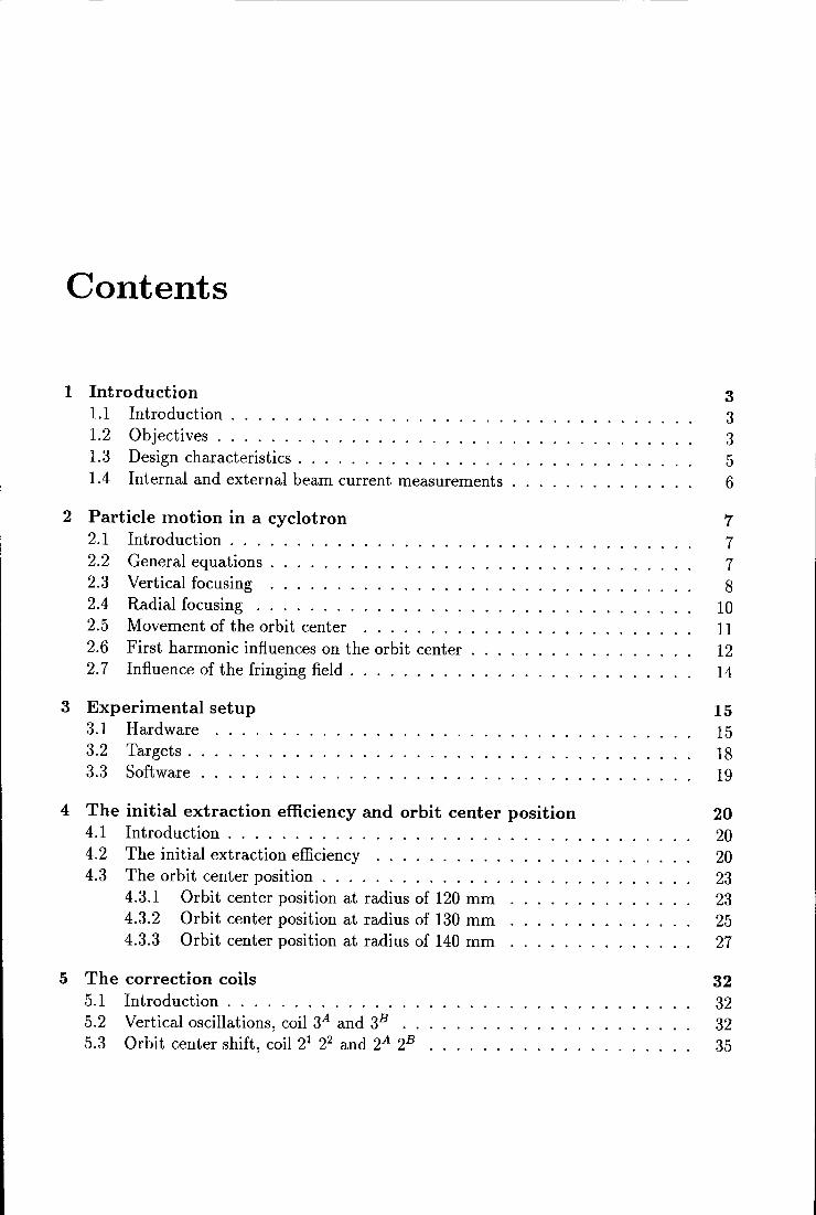
Contents
1 Introduetion 1.1 Introduetion ..... . 1.2 Objectives ...... . 1.3 Design charaeteristics . 1.4 Internal and external beam current measurements
2 Partiele motion in a cyclotron 2.1 Introduetion . . . . 2.2 General equations . 2.3 Vertical focusing . 2.4 Radial focusing . . 2.5 Movement of the orbit center 2.6 First harmonie influences on the orbit center 2. 7 Influence of the fringing field . . . . . . . . .
3 Experimental setup 3.1 Hardware 3.2 Targets . 3.3 Software .
4 The initial extraction efficiency and orbit center position 4.1 Introduetion . . . . . . . . . . . 4.2 The initial extraction efficiency ......... . 4.3 The orbit center position ............. .
4.3.1 Orbit center position at radius of 120 mm 4.3.2 Orbit center position at radius of 130 mm 4.3.3 Orbit center position at radius of 140 mm
5 The correction coils 5.1 Introduetion . . . . . . . . . . . . . . . 5.2 Vertical oscillations, coil 3A and 3B .. 5.3 Orbit center shift, coil 21 22 and 2A 2B
3 3 3 5 6
7 7 7 8
10 11 12 14
15 15 18 19
20 20 20 23 23 25 27
32 32 32 35

CONTENTS 2
6 lncreasing the extraction efficiency 40 6.1 Introduetion . . . . . . . . . . 4C 6.2 Repositioning the orbit center 40 6.3 The new extractor position .. 42
7 Conclusions, recommendations 46
A Emittance measuring system 48
B Magnetic field map measurements 52
Chapter 1
Introduetion
1.1 Introduetion
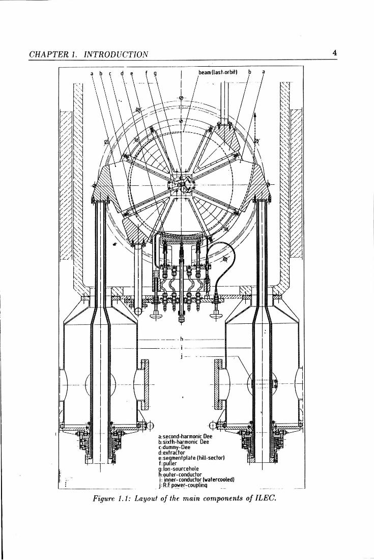
The Isochronous Low Energy Cyclotron (ILEC) is a small fixed-energy cyclotron for a 3 MeV proton beam, which has been constructed at the Cyclotron Applications Group over the last ten years. In figure 1.1 a layout of the main components of ILEC is shown.
In this chapter we first give a summary of the objectives of the minicyclotron project ILEC, and the forthcoming design-characteristics.
At the moment the cyclotron is fully in operation in 2nd harmonie mode. Internal beam currents up to a modest 10 ~-tA are possible. In the coming time, we expect the 6th harmonie system to be in operation as well, so it remains to be seen if and when the external beam meets the desired specifications.
1.2 Objectives
The objectives which form the basis for the ILEC project are :
• the design and construction should require a low financial investment,
• the cyclotron must be fit to produce a 3 Me V proton beam with low energy-spread ( < 0.1 %) for micro-beam element analysis,
• the possibility to produce high internal beam currents (up to 100 ~-tA) and for experimental study of space-charge effects.
The main difficulty evolving from these three objectives, the construction of a small machine that can fulfill these rather stringent demands on beam quality, has led to a rather complicated design.
GRAPTER 1. INTRODUCTION
(last-orbit)
-----· ---------~- 1 ----------~------
j -
a: second-harmonic Oee b:sixth-harmonic Oee c:dummy-Dee d:extrador e:segmenlplale (hili-sector) f: pu[ler g: Ion-soureehole h: outer -conductor i: inner-conductor (watercooled)
_ j: R.f p~e~-:-couplinQ
Figure 1.1: Layouf of the main components of /LEG.
4
GRAPTER 1. INTRODUCTION 5
1.3 Design characteristics
ILEC is an isochronous cyclotron. In this type of cyclotrons the average angular velocity of the accelerated particles remains constant during the accelerating process, so the frequency of the RF-signal on the accelerating dee-system can be kept constant. Because of the relativistic mass increase of the particles during acceleration, the isochronous magnetic field should increase with the radius. In oder to obtain good vertical stability of the beam in a radially increasing magnetic field, the main magnetic field is modulated azimuthally by a proper shape of the pole faces. Therefore this type of cyclotron is also called azimuthally varying field (AVF) cyclotron. For ILEC, the design of the main magnet is basedon an azimuthally varying field with four-fold rotational symmetry: four sector-shaped hills with an azimuthal width of 40°, and four valleys with an azimuthal width of 50°. The radial growth of the magnetic field is realised by increasing the heigth of the hills. The average magnetic field strength of approximately 1.42 T is generated by two relatively small (hence cheap) main coils of 140x 192 ampère turns each. This implies the construction of a very small gap between the magnet poles, which should provide just enough space for the RF accelerating structure and the correction coils.
The RF accelerating structure used in ILEC consists of two pairs of dees. One pair, the seeond harmonie dee system, is placed in two opposite valleys of the poles, to keep the magnet gap as smallas possible. Because the azimuthal extent of these dees is limited by the width of the valleys, we have two dees with an azimuthal width of 50°, operated in second harmonie push-push mode. This means that both dees are excitated in phase, at two times the revolution frequency of the accelerated protons.
In order to achieve the lowest possible energy spread at high beam currents a second pair of smaller dees, the sixth harmonie dee system, is placed between the hills of the upper and lower magnet poles. When these dees are operated in sixth harmonie mode, with proper phase and amplitude in respect to the second harmonie dee voltage, the sinusoidal shape of the basic (second harmonie) accelerating voltage is e:ffectivelly altered into a more blockshaped fashion [9]. This technique is called flat-topping: adding odd higher harmonies to the basic accelerating voltage makes the energy gain per turn less dependent of the partiele phase, thus resulting in wider phase acceptance and lower energy-spread. Because the sixth harmonie dee system only effects beam quality, the basic operation mode of ILEC involves only second harmonie acceleration.
The internal ion souree used in ILEC is positioned near the center, trough a 2 cm hole in the yoke. It is a self-heating PIG-source, described by Bennet [2], which has been scaled down to the desired proportions.
After the last revolution (at a radius of approximately 16 cm), the particles are extracted from their circular orbits by an electrastatic deflector, the extraetor. The extrador is constructed according to a classica! design [3], already used in former small cyclotrons. Aft er passing the extrador, the i ons have to pass for the last time the 2nd harmonie dee system (see tigure 1.1). After this last accelaration, the ions will leave the main magnetic field. In ILEC, the narrow magnet gap produces a strong negative gradient of the magnetic field towards the edge. This causes the extracted beam to diverge excessively
GRAPTER 1. INTRODUCTION 6
in the horizontal direction. To compensate this defocussing influence of the fringing field, a magnetic channel is fixed between the upper and lower conductors of the second harmonie dees. The magnetic focusing channel used in ILEC was designed by de Regt (4], and is of the passive type. The small iron bars of which it is constructed adapt the local main magnetic field such that the extracted particles encounter a positive field gradient, providing the necessary refocussing.
1.4 lnternal and external beam current measurements
The experiments involved in this report are beam current measurements as a fundion of the radius. The beam current was measured in three different ways: differential, integral and as a fundion of the height distribution with a three finger target.
The differential measurements were clone with a tantalum wire target of 0.1 mm in width. Sirree the width of this target is much smaller then that of the beam, individual orbits can he measured with this target. The integral measurements were clone with a thick solid target so that a beam current as a fundion of the radius is measured. Loss of current towards higher orbits can easily he found with this target. The differential and integral targets are combined in one radial movable device.
The three finger target is used to measure the current distribution as a fundion of the height. It consist of two small metal strips mounted on an integral target intercepting perpendicular the beam. Loss of current due to vertical drift or blow up of the beam can be measured with this target.
All of the targets were designed in such a way that they could be mounted on the already existing target manipulator. This manipulator is mounted in the median plane of the cyclotron and can move towards the center from a radius of 200 mm down to 50 mm.
The manipulation of the target position and measuring of the various currents is clone using a Phydas data acquisition computer. This measuring computer involves several analog to digital converters (ADC), angle decoders and relay interfaces. The ADC's are used for measuring the various beam currents, the angle decoder for the position detection of the manipulator and the relay interface masters a steppermotor interface which controls the manipulator position. The main advantage of a steppermotor over a servomotor is that speed and direction can easily be controlled by a computer. At the present the speed is fixed, however future developments may need variabie speed. In the measuring interval the angle encoder generates 9872 pulses, so an accuracy of 15 11m in the target position can be accomplished. By measuring consistently in the inwards direction static measuring errors can be avoided.
Chapter 2
Partiele motion in a cyclotron
2.1 Introduetion
The theory of orbit trajectories in azimuthally varying field cyclotrons is very complex. In order to understand the influence of small magnetic induction variations created by the various correction coils, the theory of a rotational symmetrie magnetic induction is used. In the first and second section of this chapter the conditions for the shape of the magnetic induction for radial and vertical stability according to this theory are given.
For extraction of the internal beam the fringing field has to he crossed. In order to keep the conditions of isochrony upright until extraction the orbit center has to coincide with the geometrie center of the cyclotron or to drift slightly in the direction of the extractor. The movement of the orbit center due to the radial decrease of the magnetic induction and due to asymmetrie magnetic induction distortions is derived in the sections 2.5 and 2.6 of this chapter. These magnetic induction distortions can he created by asymmetrie excitation of the various correction coils.
In the last part of this chapter the influence of the fringing field on the beam properties is sketched.
2.2 General equations
The partiele motion in a cyclotron can he described with the general equation 2.1
d --+ --+
dt ( mv) = e( E + v x B) (2.1)
In this equation v is the velocity, m the mass and e the charge of the particle. Ë and B represent the electrical field and the magnetic induction. In cylindrical coordinates, in a
GRAPTER 2. PARTICLE MOTION IN A CYCLOTRON
right hand system this equation becomes
d . .2 -(mr)- mrO dt
1 d 2. --(mr 0) ï dt
d . dt (mz)
eEr- erOEz + eiEo
8
(2.2)
(2.3)
(2.4)
where the dots indicate differentiation with respect to the time. From equation 2.2 one can derive the well known equation for a non relativistic charged partiele in a homogeneaus magnetic induction (Eo =Er= 0, Er= 0)
2.3 Vertical focusing
. e () = -Ez
m (2.5)
The vertical motion in a homogeneaus magnetic induction (if Ez = 0) is not focused, as can be seen from equation 2.4
!(mi)= 0 (2.6)
Particles with an initial velocity in the vertical direction willleave the median plane and will be lost. Equation 2.4 demonstrates that Eo and Er can accomplish vertical focusing in the median plane. Using V x Ë = 0, one can linearize Er and Eo around z = 0, giving
(2.7)
Eo = (2.8)
So radial and/or azimuthal magnetic induction variations must be present to ensure vertical stability. In a classica! cyclotron the magnetic induction is rotationally symmetrie (Eo = 0) and from equation 2.4 one can calculate the field shape necessary for vertical stability. Using equation 2.7 and neglecting higher ordertermsof Er one can obtain
d · · 8Ezl dt (mi)= erOEr ~ erOz Br z=o (2.9)
So vertical focusing is accomplished for Ó > 0 when 8!/r• L=o < 0, i.e. the magnitude of the magnetic induction must decrease towards larger radii. From relation 2.9 one can derive the vertical oscillation frequency Vz. This Vz describes
GRAPTER 2. PARTICLE MOTION IN A CYCLOTRON 9
the vertical displacement of a partiele as a function of the angle in the median plane. By neglecting the relativistic mass increase, this relation can be written as
(2.10) z=O
We now introduce the magnetic induction index n = - !Jz 8:/.
Differentiation of equation 2.10 with respect to the angle () insteadof the time will result in an easy to solve relation
(2.11)
The salution of this equation is a simple harmonie oscillator with frequency -Jn = Vz, where 1/vz is the number of vertical oscillatory periods around the horizontal median plane per revolution of a particle. The magnetic induction index n must be positive, resulting in a decreasing magnetic induction towards larger radii as mentioned before. However a phase slip is introduced since the magnitude of the magnetic induction will not be exactly isochronous everywhere.
Up to 1950 all cyclotrons had such a rotationally symmetrie field. The problem with this type of machine is the limited maximum energy. In the above sketched relation, the relativistic mass increase is neglected. Relation 2.5 shows that an increase of the mass causes a decrease of the angular velocity. So a phase slip is introduced between the fixed acceleration frequency and the revolution frequency. This phase slip increases while going to higher energies until de-acceleration occurs. To compensate for this mass increase, the magnetic induction should increase towards larger radii. To overcome the vertical instability, an azimuthally varying field (AVF) is introduced.
In an AVF cyclotron Be -=f. 0. Relation 2.4 combined with relation 2.8 will become
d( ") "B .z8Bz - mz = -er e ~ -er- --& r 00 (2.12)
z=O
So vertical focusing will now occur when r 88~· > 0. This can be realized by sector shaped hills and valleys in the magnet poles, which establish azimuthally variation of the magnetic field.
In a hill the curvature of the orbit will be strong, in the valleys small. So entering a hill sector will make r > 0 and leaving the hill r < 0. The magnetic induction in the hill is stronger than in the valleys resulting in 8Jlez > 0 upon entering and 8f/ez < 0 when leaving. The net result is r8:z > 0. So an AVF cyclot.ron can accelerate relativistic particles by an increase of the azimuthally averaged field Bz with r, while still keeping vertical focusing effective.
The equation for the vertical asciilation frequency is now becoming far more complicated
CHAPTER 2. PARTICLE MOTION IN A CYCLOTRON 10
than Vz = i-'.'111.: Because of the angular periodical shape of an AVF, the field can be r
developed into Fourier series. In the median plane the magnetic field is then given by
B(r, 0) = il(r) ( 1 + ~ [A.(r) cos( kO) + B>Sin( kO)J) (2.13)
Here B(r) is the average field on a given radiusrand Ak, Bk are the Fourier components representing the field flutter. With this representation of the magnetic field the new Vz can be calculated by making use of Hamilton mechanics [8]
(2.14)
H A' d A d A" 2 d2 A ere k = r dr k, an k = r dr2 k.
2.4 Radial focusing
The radial stability in a classica! cyclotron can be derived at a similar manner as the vertical stability. For a classical magnetic induction, relation 2.2 will become for a non accelerated motion
d . "2 • dt (mr)- mr8 = -er8Bz (2.15)
The radius of an equilibrium orbit for a partiele with velocity v is
(2.16)
We note that an equilibrium orbit is an orbit lying in the median plane which in itself is closed in one revolution and is described by a partiele that is not accelerated. lts center of symmetry is the fixed orbit center. Ideally the center of an equilibrium orbit coincides with the geometrie center of the cyclotron. Consicier now a partiele with a small deviation from the equilibrium orbit r(t) = r0 + x(t). The radial motion is now described in the first order by [3]
m d2
x = mv2
(1 - _:_) - evBz(ro) (1 + x aBz I ) (2.17) dt2 r0 r0 Bz(ro) 8r ro
or
(2.18)
With t = (} jw this becomes
(2.19)
CHAPTER 2. PARTICLE MOTION IN A CYCLOTRON 11
Using the field index n, this relation is
d2x d()2+(1-n)x=0 (2.20)
The radial oscillation frequency will be Vr = vr=-;ï, where 1/vr is the number of periods per revolution around an equilibrium orbit. For radial stability 1- n > 0. Combining with the condition for vertical stability n > 0 leads to 0 < n < 1. For an AVF cyclotron, the relation for Vr is very complex. By making use of Hamilton mechanics it can be written as [8]
1 "' [ 3P ( 2 2) 5k2
- 8 ( I I) 1- 2n + 7 4(k2- 1)(k2- 4) Ak +Bk + 4(k2- 1)(k2- 4) AkAk + BkBk +
1 (A A"+ B B") + 1
(A"2 + B"2)] (2.21) 4(k2- 1) k k k k 4(k2- 4) k k
2.5 Movement of the orbit center
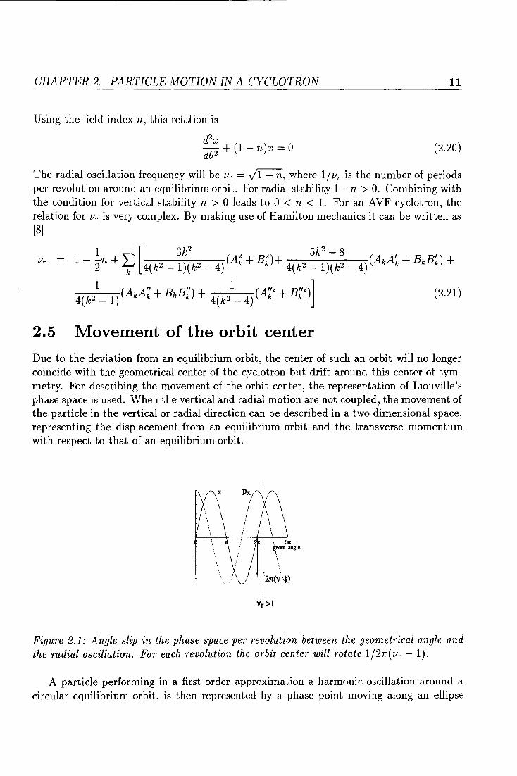
Due to the deviation from an equilibrium orbit, the center of such an orbit will no longer coincide with the geometrical center of the cyclotron but drift around this center of symmetry. For descrihing the movement of the orbit center, the representation of Liouville's phase space is used. When the vertical and radial motion are not coupled, the movement of the partiele in the vertical or radial direction can be described in a two dimensional space, representing the displacement from an equilibrium orbit and the transverse momenturn with respect to that of an equilibrium orbit.
Vr>l
Figure 2.1: A ngle slip in the phase space per revolution between the geometrical angle and the radial oscillation. For each revolution the orbit center will rotate 1 /27r( Vr - 1).
A partiele performing in a first order approximation a harmonie oscillation around a circular equilibrium orbit, is then represented by a phase point moving along an ellipse
GRAPTER 2. PARTICLE MOTION IN A CYCLOTRON 12
in the corresponding phase plane, the so called eigenellips. The frequency with which the phase point is rotating is equal to the asciilation frequency of the particle, Vr or Vz.
For a circular scaled eigenellips, the orbit center movement can be derived in a simple way. Suppose that the radial asciilation frequency Vr should is somewhat larger then unity. So after one geometrical revolution of the particle, the point representing the partiele in the phase space will have gained a small angle with respect to the previous revolution ( see :figure 2.1). This angle per revolution is 27r(vr- 1).
phase space
for a partiele at 9=0•
A
orbit pertmbation
due to radial deviation
B
orbit perturbation
due to momentum deviation
c
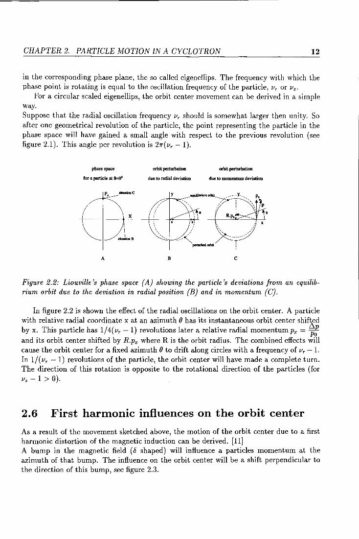
Figure 2.2: Liouville 's phase space (A) showing the partiele's deviations from an equilibrium orbit due to the deviation in radial position (B) and in momenturn (C).
In :figure 2.2 is shown the effect of the radial oscillations on the orbit center. A partiele with relative radial coordinate x at an azimuth (} has its instantaneous orbit center shifted by x. This partiele has 1/ 4( Vr - 1) revolutions later a relative radial momenturn Px = ~: and its orbit center shifted by R.px where Ris the orbit radius. The combined effects will cause the orbit center for a :fixed azimuth (} to drift along circles with a frequency of Vr - 1. In 1/(vr- 1) revolutions of the particle, the orbit center will have made a complete turn. The direction of this rotation is opposite to the rotational direction of the particles (for Vz- 1 > 0).
2.6 First harmonie influences on the orbit center
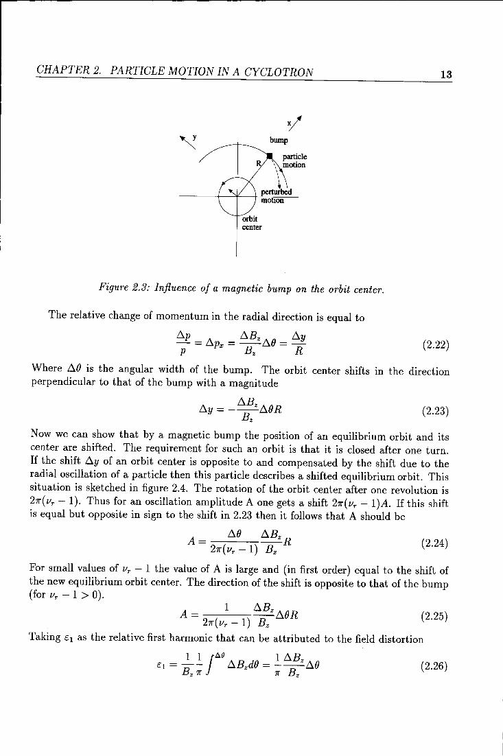
As a result of the movement sketched above, the motion of the orbit center due to a first harmonie distartion of the magnetic induction can be derived. [11] A bump in the magnetic field (b shaped) will in:fluence a particles momenturn at the azimuth of that bump. The in:fluence on the orbit center will be a shift perpendicular to the direction of this bump, see :figure 2.3.
GRAPTER 2. PARTICLE MOTION IN A CYCLOTRON
bump
partiele \ motion
I I I
+ perturbed motion
orbit center
Figure 2.3: Infiuence of a magnetic bump on the orbit center.
The relative change of momenturn in the radial direction is equal to
Llp _ A _ LlBz A() _ Lly - upx- u -
p Bz R
13
(2.22)
Where il() is the angular width of the bump. The orbit center shifts in the direction perpendicular to that of the bump with a magnitude
ily = - ilBz il()R Bz
(2.23)
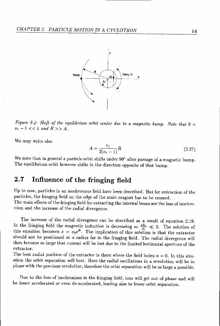
Now we can show that by a magnetic bump the position of an equilibrium orbit and its center are shifted. The requirement for such an orbit is that it is elosed after one turn. If the shift Lly of an orbit center is opposite to and compensated by the shift due to the radial oscillation of a partiele then this partiele describes a shifted equilibrium orbit. This situation is sketched in figure 2.4. The rotation of the orbit center after one revolution is 21l'(vr- 1). Thus for an oscillation amplitude A one gets a shift 21l'(vr- 1)A. If this shift is equal but opposite in sign to the shift in 2.23 then it follows that A should he
(2.24)
For small values of Vr - 1 the value of A is large and (in first order) equal to the shift of the new equilibrium orbit center. The direction of the shift is opposite to that of the bump (for Vr - 1 > 0).
A= 1 LlBz il()R (2.25) 21l'(Vr- 1) Bz
Taking é 1 as the relative first harmonie that can he attributed to the field distortion
(2.26)
CHAPTER 2. PARTICLE MOTION IN A CYCLOTRON
bump
' ' ' ' ' ' ' ' ' ',,.__
y
R 2n(vrl)
14
x
Figure 2.4: Shift of the equilibrium orbit center due to a magnetic bump. Note that 0 < Vr - 1 < < 1 and R > > A.
We may write also
(2.27)
We note that in general a partiele orbit shifts under 90° after passage of a magnetic bump. The equilibrium orbit however shifts in the direction oppesite of that bump.
2. 7 Influence of the fringing field
Up to now, particles in an isochronous field have been described. But for extraction of the particles, the fringing field on the edge of the main magnet has to be crossed. The main effects of the fringing field for extrading the internal beam are the loss of isochronism and the increase of the radial divergence.
The increase of the radial divergence can be described as a result of equation 2.19. In the fringing field the magnetic induction is decreasing so ~ ~ 0. The solution of this equation becomes x = x 0e9
. The implication of this solution is that the extractor should not be positioned at a radius far in the fringing field. The radial divergence will then become so large that current will be lost due to the limited horizontal aperture of the extractor.
The best radial position of the extractor is there where the field index n = 0. In this situation the orbit separation will best. Here the radial oscillations in a revolution will be in phase with the previous revolution, therefore the orbit separation will be as large a possible.
Due to the loss of isochronism in the fringing field, ions will get out of phase and will be lesser accelerated or even de-accelerated, leading also to lesser orbit separation.
Chapter 3
Experimental setup
In this report various internal beam current measurements are descri bed. To performthese measurements, computer controlled interfaces have been fabricated in order to measure currents and target positions. The computer system and the various targets are described in this chapter.
3.1 Hardware
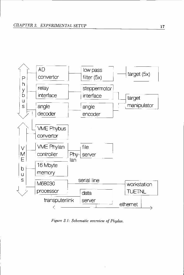
At the Department of Applied Physics, a data acquisition system has been developed called Phydas (Physical Data Acquisition System). A schematic diagram of this system can be seen in figure 3.1. This measuring system consists, unlike common computers, of two data busses; the Phybus and the VME-bus. The Phybus handles the control of the measuring interfaces. The VME bus controls the data storage and takes care of control of the Phybus using the VME/Phybus interface. To the VME bus a M68030 microprocessor is attached which uses the local 16 MByte memory. The software for control of the measurement is storedon a central memory disk; the file server. The access to this disk is clone by Phylan. Phylan is a local area network of the faculty which all users of Phydas can use for storage of data and software.
An other way of data storing is by using the transputer link. This link makes it possible to store data on the local data server, a common IBM compatible PC. By connecting the data server to the Ethernet, data can be stored on the memory disk of the VAX were it can he post processed. All the data acquisition in this report is clone by using the Transputer link.
The software program for target manipulation and data acquisition, named TARGET is written in PEP. The program uses three different interfaces; an eight channel analog to digital converter (ADC), an angle decoder and a relay interface.
The targets are connected toa 1 Mn resistor, so the intercepted beam currents (in the order of 1JlA) can be converted into an appropriate digital value by the ADC.
GRAPTER 3. EXPERIMENTAL SETUP 16
The movable target is mounted on a cogwheel driven rod. The position can be varied along the radius of the cyclotron from 50.0 to 201.2 mm. This cogwheel is driven by a steppermotor. The steppermotor interface that controls this steppermotor is handled by a relais interface. In the future this steppermotor can be controlled directly by Phydas by using a steppermotor interface instead of the relay interface. Direct control offers the advantage of variabie target speed in contradiction to control with a relay interface. The position of the target manipulator is converted into counts by an angle encoder which is mounted on the cogwheel. The number of counts is proportional to the displacement of the manipulator. By using the boundary positions of the manipulator as a reference, counts can be converted into a position. The counts are converted into a digital value by the angle decoder. The angle en co der generates 9872 counts between these boundaries so an accuracy of 15 11m is achieved. Measuring is clone every 0.105 mm to avoid excessively large data files.
CHAPTER 3. EXPERIMENTAL SETUP 17
AD low pass target (5x) f------
p convertor filter (5x) h y f----
relay steppermotor
interface l target b interface u r manipulator s angle angle
f----'---------
decoder eneader
L__ VME Phybus f----
convertor
V VME Phylan file '----
M controller Phy- server E lan
b -16 Mbyte
u memory s serialline
M68030 workstation f--
processor data TUETNL
transputerlink server ethernet / I " " /
Figure 3.1: Schematic overview of Phydas.
GRAPTER 3. EXPERIMENTAL SETUP 18
targe·~-~ 9=135° .
·· .. ,"' r
.. extr. target
,../ 9=2S0
L-...-~~L_._~~l<-'-~'---'--'..L...-..~1----"--' x 20
~ extractor
'-.target A
9::31S' dee
Figure 3.2: Target configuration.
3.2 Targets
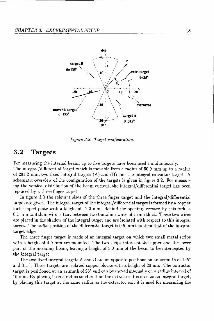
For measuring the internal beam, up to five targets have been used simultaneously. The integral/ differential target which is movable from a radius of 50.0 mm up to a radius of 201.2 mm, two fixed integral targets (A) and (B) and the integral extractor target. A schematic overview of the contiguration of the targets is given in figure 3.2. For measuring the vertical distri bution of the beam current, the integral/ differential target has been replaced by a three finger target.
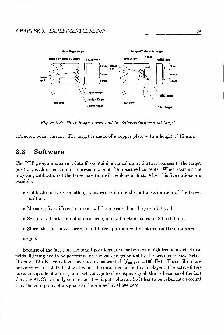
In figure 3.3 the relevant sizes of the three finger target and the integral/ differential target are given. The integral target of the integral/ differential target is formed by a copper fork-shaped plate with a height of 12.0 mm. Behind the opening, created by this fork, a 0.1 mm tantalum wireis taut between two tantalum wires of 1 mm thick. These two wires are placed in the shadow of the integral target and are isolated with respect to this integral target. The radial position of the differential target is 0.5 mm less then that of the integral target edge.
The three finger target is made of an integral target on which two small metal strips with a height of 4.0 mm are mounted. The two strips intercept the upper and the lower part of the incoming beam, leaving a height of 5.0 mm of the beam to he intercepted by the integral target.
The two fixed integral targets A and B are on opposite positions on an azimuth of 135° and 315°. These targets are isolated copper blocks with a height of 20 mm. The extractor target is positioned at an azimuthof 25° and can he moved manually on a radius interval of 10 mm. By placing it on a radius smaller than the extractor it is used as an integral target, by placing this target at the same radius as the extractor exit it is used for measuring the
CHAPTER 3. EXPERIMENTAL SETUP 19
three f"mger target Integrai{Differential target
front view (seen by beam) radial view front view 4mm ~ radial view
top view topview , lower flnger
Figure 3.3: Three finger target and the integraljdifferential target.
extracted beam current. The target is made of a copper plate with a height of 15 mm.
3.3 Software
The PEP program creates a data file containing six columns, the first represents the target position, each other column represents one of the measured currents. When starting the program, calibration of the target position will be clone at first. After this five options are possible:
• Calibrate; in case something went wrong during the initial calibration of the target position.
• Measure; five different currents will be measured on the given interval.
• Set interval; set the radial measuring interval, default is from 180 to 60 mm.
• Store; the measured currents and target position will be storedon the data server.
• Quit.
Because of the fact that the target positions are near by strong high frequency electrical fields, filtering has to be performed on the voltage generated by the beam currents. Active filters of 12 dB per octave have been constructed Ucut off =100 Hz). These filters are provided with a LCD display at which the measured current is displayed. The active filters are also capable of adding an offset voltage to the output signal, this is because of the fact that the ADC's can only convert positive input voltages. Soit has tobetaken into account that the zero point of a signal can be somewhat above zero.
Chapter 4
The initia! extraction efficiency and orbit center position
4.1 Introduetion
In the past only a small part of the internal beam could he extracted. In order to determine if the electrastatic extractor or the magnetic channel was intercepting the beam, measurements of t.he beam current directly behind the electrastatic extractor have been performed. One of these measurements is displayed in the second section of this chapter.
In order to minimize the influence of the fringing field and thereby increasing the extraction efficency, the internal beam has to he well centered. This can he clone by activation of the correction coils. Since the correction coils had to he set at their maximum strength for maximum extracted current, it seemed to he that the orbit center was not at the correct place, so the orbit center position of the outer revolutions was measured. These measurements are displayed in the third section of this chapter.
4.2 The initial extraction efficiency
As described in the introduetion of this chapter, the main problem of ILEC was the low extraction efficiency. In figure 4.1 the internal current is displayed as a function of the radius and the current that has passed the extractor while bringing the integral target to a lower radius.
GRAPTER 4. THE INITIAL EXTRACTION EFFICIENCY AND ORBIT CENTER POSITION 21
4 ~------------------------~ -Int. -- Extr.
3
2.4 2
---------------------~~1
-10.5
1
0 .",.,.,.".......,.,..._ ... ___ ",_"0\11..., ....
60 80 100 120 140 160 180
radius [mm]
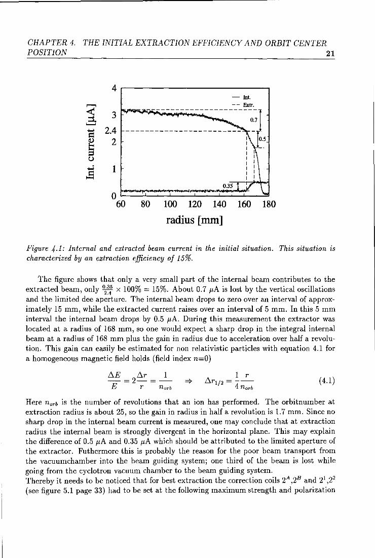
Figure 4.1: Internat and extracted beam current in the initia! situation. Th is situation is characterized by an extraction efficiency of 15%.
The figure shows that only a very small part of the internal beam contributes to the extracted beam, only 02~: x 100% = 15%. About 0.7 11A is lost by the vertical oscillations and the limited dee aperture. The internal beam drops to zero over an interval of approximately 15 mm, while the extracted current raises over an interval of 5 mm. In this 5 mm interval the internal beam drops by 0.5 JlA. During this measurement the extrador was located at a radius of 168 mm, so one would expect a sharp drop in the integral internal beam at a radius of 168 mm plus the gain in radius due to acceleration over half a revolution. This gain can easily he estimated for non relativistic particles with equation 4.1 for a homogeneaus magnetic field holds (field index n=O)
D..E = 2D..r = _I_ E r norb
1 r D..rl/2 = ---
4 norb (4.1)
Here norb is the number of revolutions that an ion has performed. The orbitnumber at extraction radius is about 25, so the gain in radius in half a revolution is 1.7 mm. Since no sharp drop in the internal beam current is measured, one may conclude that at extraction radius the internal beam is strongly divergent in the horizontal plane. This may explain the difference of 0.5 11A and 0.35 11A which should he attributed to the limited aperture of the extractor. Futhermore this is probably the reason for the poor beam transport from the vacuumchamber into the beam guiding system; one third of the beam is lost while going from the cyclotron vacuum chamber to the beam guiding system. Thereby it needs to he noticed that for best extraction the correction coils 2A ,2B and 21 ,22
(see figure 5.1 page 33) had to he set at the following maximumstrengthand polarization
GRAPTER 4. THE INITIAL EXTRACTION EFFICIENCY AND ORBIT CENTER POSITION 22
( + strengtherring the main field, - weakening):
coil strength [A J polarization 2 20 2B 20 + 21 20 22 20 +
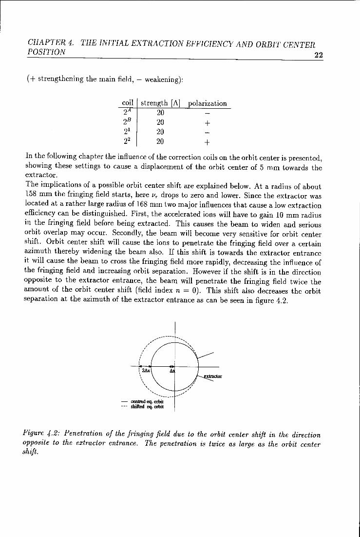
In the following chapter the influence of the correction coils on the orhit center is presented, showing these settings to cause a displacement of the orhit center of 5 mm towards the extractor. The implications of a possihle orhit center shift are explained helow. At a radius of ahout 158 mm the fringing field starts, here llr drops to zero and lower. Sirree the extractor was located at a rather large radius of 168 mm two major influences that cause a low extraction efficiency can he distinguished. First, the accelerated ions will have to gain 10 mm radius in the fringing field hefore heing extracted. This causes the heam to widen and serious orhit overlap may occur. Secondly, the heam will hecome very sensitive for orhit center shift. Orhit center shift will cause the ions to penetrate the fringing field over a certain azimuth therehy widening the heam also. If this shift is towards the extractor entrance it will cause the heam to cross the fringing field more rapidly, decreasing the influence of the fringing field and increasing orhit separation. However if the shift is in the direction opposite to the extractor entrance, the heam will penetrate the fringing field twice the amount of the orhit center shift (field index n = 0). This shift also decreases the orhit separation at the azimuthof the extractorentrance as can heseen in figure 4.2.
",. ......... -I
/ /
I
/
I , : I
\2Ax I I I \
\
'' ...... ....... __ _
- centred eq. orbit --- shifted eq. orbit
Figure 4.2: Penetration of the fringing field due to the orbit center shift in the direction opposite to the extrador entrance. The penetration is twice as large as the orbit center shift.
CHAPTER 4. THE INITIAL EXTRACTION EFFICIENCY AND ORBIT CENTER POSITION 23
4.3 The orbit center position
For measuring the center position, all integral targets have been used: target A,B the extractor target and the moving integral target. For the sake of clearness, the target on the azimuthof the extractor exit is called the 'extractor target' in spite of the fact that in this section this target is located on a radius much smaller that the extractor exit measuring therefor internal current instead of extracted current.
The orbit center position is measured by placing two integral targets at an azimuth diametral to one another at such a radius that both targets intercept half the internal beam. The difference in radial position of the two targets will then he equal to twice the orbit center shift. Here one has to correct for the gain in radius due to the acceleration over half a revolution. This gain has been measured with the differential targets since the orbit separation is equal to twice this gain. The orbit center shift has been measured in two directions, in the direction of the targets A and B and in the direction of the differential/integral target and the extractor target. All measurements have been performed with the first harmonie correction coils switched off. The orbit center position has been measured at a radial position of target A of 121, 131 and 141 mm.
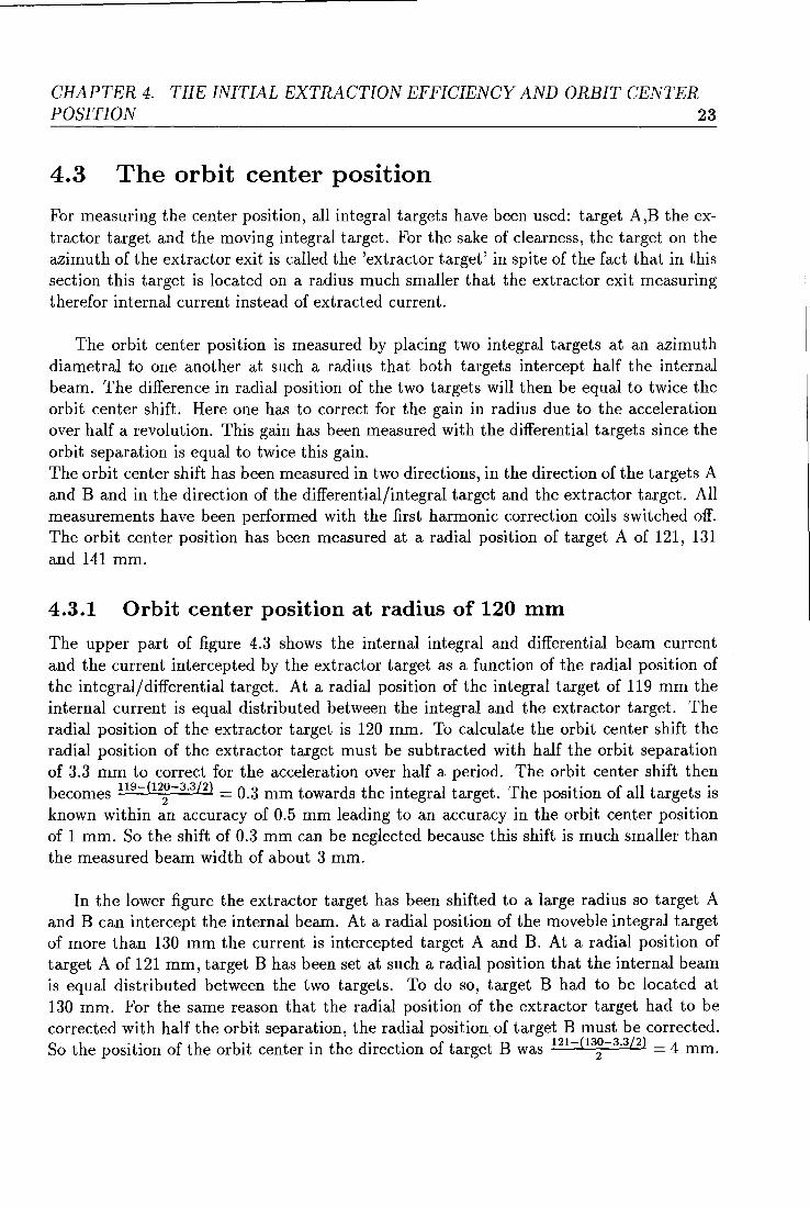
4.3.1 Orbit center position at radius of 120 mm
The upper part of figure 4.3 shows the internal integral and differential beam current and the current intercepted by the extractor target as a function of the radial position of the integral/differential target. At a radial position of the integral target of 119 mm the internal current is equal distributed between the integral and the extractor target. The radial position of the extractor target is 120 mm. To calculate the orbit center shift the radial position of the extractor target must he subtracted with half the orbit separation of 3.3 mm to correct for the acceleration over half a period. The orbit center shift then becomes 119-(12~-3 ·3/2 ) = 0.3 mm towards the integral target. The position of all targets is known within an accuracy of 0.5 mm leading to an accuracy in the orbit center position of 1 mm. So the shift of 0.3 mm can he neglected because this shift is much smaller than the measured beam width of about 3 mm.
In the lower figure the extractor target has been shifted to a large radius so target A and B can intercept the internal beam. At a radial position of the movebie integral target of more than 130 mm the current is intercepted target A and B. At a radial position of target A of 121 mm, target B has been set at such a radial position that the internal beam is equal distributed between the two targets. To do so, target B had to he located at 130 mm. For the same reason that the radial position of the extractor target had to he corrected with half the orbit separation, the radial position of target B must he corrected. S h . . f h b" . th d" t" ft t B 121-(130-3.3/2) 4 o t e posit10n o t e or It center m e 1rec Ion o arge was 2 = mm.
CHAPTER 4. THE INITIAL EXTRACTION EFFICIENCY AND ORBIT CENTER POSITION 24
Rextr= 120 mm 4
-- Int ..... Extr. 6 ,......, ,......,
,. ........ \J" .. \.,.1'"'\,"'"\.""._..,......,...,.~ .... ".., ...... ~"'~ .
< 3 - Diff. :::::::1
:i I C'd L........J I, .... ~ ..... ~-·~
L........J
d \ I 4 ~ I I
~ 2 1/
C)
Vf C)
~ 1 2 ~ ! ·~
~ )
' 0 \i V \
0 V V i '· 0
60 80 100 120 140
radius [mm]
RA= 121 mm RB= 130 mm 3 5
-- Int
2.5 1 '.., Ir ... .,~~, "'••, ,. ... ".....,'-"""••"'V"t.oV•r\ ..... A ,......, ,......,
4 .
1 ~--- B ~ 1- Diff. cO
L........J 2 I L........J
~ I 3 ~
~ I d
1.5 Q.) s V ~\ ;,:~~~ 2
C) 1 C) I
~ ,..J ~ ~ 0.5
{I 1 .:\\ 0 t: I
~ ~.~ .... ~ ....... ·~-.--) \ 0 0 60 80 100 120 140
radius [mm]
Figure 4.3: Beam current measurement with the extractor target at a radial position of 120 mm (upper figure) and with target A located at 121 mm and target B located at 130 mm (lower figure). The orbit center is shifted towards target B by 4 mm.
GRAPTER 4. THE INITIAL EXTRACTION EFFICIENCY AND ORBIT CENTER POSITION 25
4.3.2 Orbit center position at radius of 130 mm
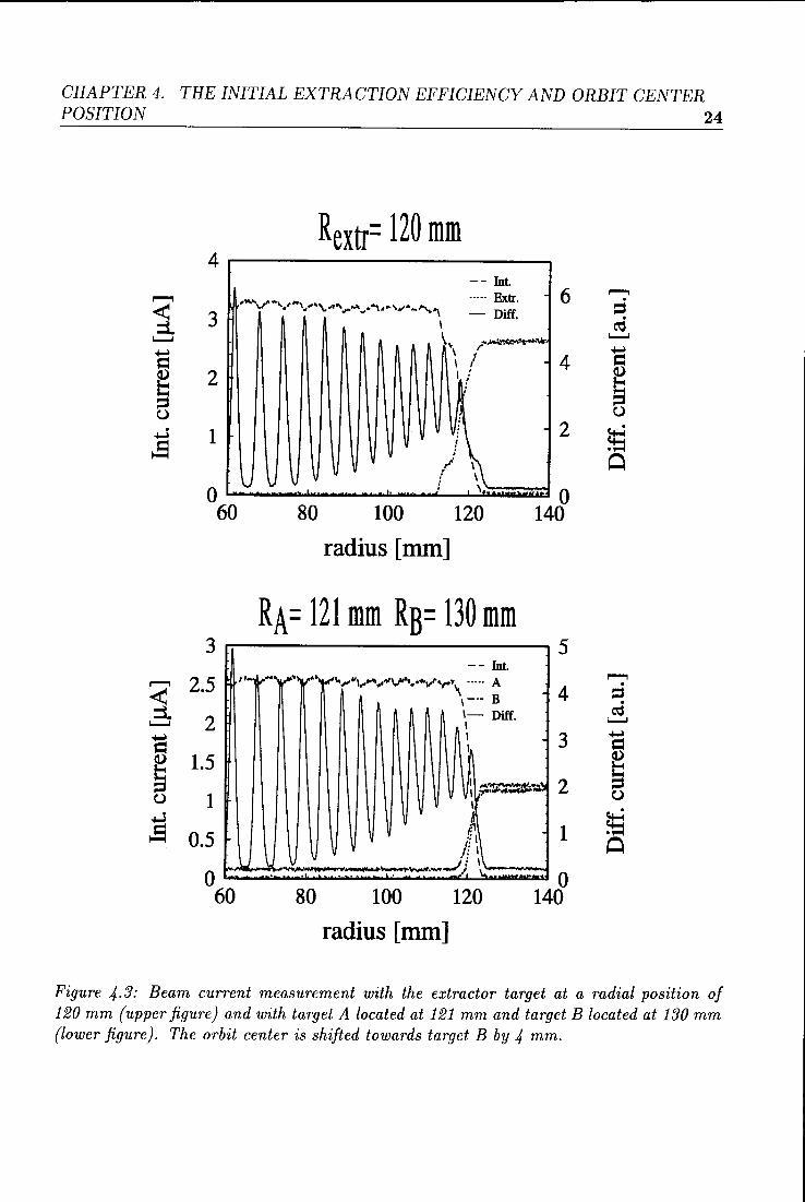
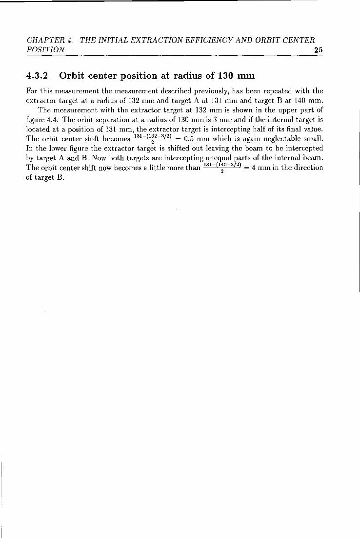
For this measurement the measurement described previously, has been repeated with the extractor target at a radius of 132 mm and target A at 131 mm and target B at 140 mm.
The measurement with the extractor target at 132 mm is shown in the upper part of figure 4.4. The orbit separation at a radius of 130 mm is 3 mm and if the internal target is located at a position of 131 mm, the extractor target is intercepting half of its final value. The orbit center shift becomes 131 -( 1~2-3/2 ) = 0.5 mm which is again neglectable small. In the lower figure the extractor target is shifted out leaving the beam to be intercepted by target A and B. Now both targets are intercepting unequal partsof the internal beam. The orbit center shift now becomes a little more than 131 -(l~0-3/2 ) = 4 mm in the direction of target B.
CHAPTER 4. THE INITIAL EXTRACTION EFFICIENCY AND ORBIT CENTER POSITION 26
Rextr. = 132 mm 2 ~----------------------~
-- Int ····- E 6 - Diff.
radius [mm]
RA= 131 mm RB= 140 mm 2.5 .----------------,
-- Int -----A
2 8
1.5
1
:s 0.5 2
0 W&.ie~~~illlli:al.&.:.~~.r....t.llliiii~~L..Iii!lliit 0 M ~ 100 1W 1~
radius [mm]
Figure 4.4: Beam current measurement with the extractor target at a radial position of 132 mm (upper figure) and with target A located at 131 mm and target B located at 140 mm. The orbit center is shifted towards target B by 4 mm.
CHAPTER 4. THE INITIAL EXTRACTION EFFICIENCY AND ORBIT CENTER POSITION 27
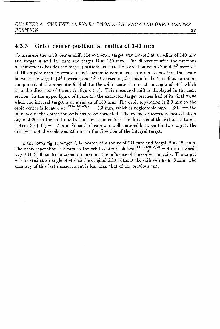
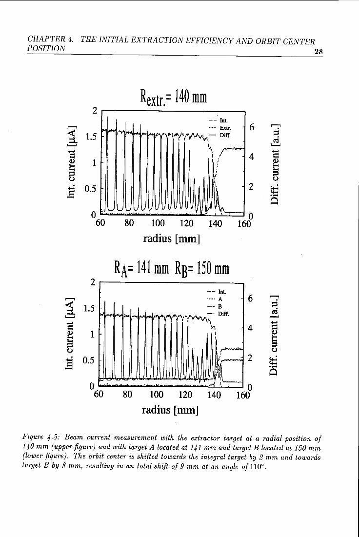
4.3.3 Orbit center position at radius of 140 mm
To measure the orbit center shift the extractor target was located at a radius of 140 mm and target A and 141 mm and target B at 150 mm. The difference with the previous measurements,besides the target positions, is that the correction coils 2A and 2B were set at 10 ampère each to create a first harmonie component in order to position the beam between the targets (2A lowering and 2B strengtening the main field). This first harmonie component of the magnetic field shifts the orbit center 4 mm at an angle of -45° which is in the direction of target A ( figure 5.1). This measured shift is displayed in the next section. In the upper figure of figure 4.5 the extractor target reaches half of its final value when the integral target is at a radius of 139 mm. The orbit separation is 3.0 mm so the orbit center is located at 139
-(1:
0-
3/
2) = 0.3 mm, which is neglectable small. Still for the
influence of the correction coils has to be corrected. The extractor target is located at an angle of 20° so the shift due to the correction coils in the direction of the extractor target is 4 cos(20 + 45) = 1. 7 mm. Since the beam was well centered between the two targets the drift without the coils was 2.0 mm in the direction of the integral target.
In the lower figure target A is located at a radius of 141 mm and target B at 150 mm. The orbit separation is 3 mm so the orbit center is shifted 141 -(l;o-3
/2
) = 4 mm towards target B. Still has to betaken into account the influence of the correction coils. The target A is located at an angle of -45° so the original drift without the coils was 4+4=8 mm. The accuracy of this last measurement is less than that of the previous one.
GRAPTER 4. THE INITIAL EXTRACTION EFFICIENCY AND ORBIT CENTER POSITION 28
Rextr. = 140 mm 2r---------------,
-- Int ,......., ~-.... . .... Exlr. 6 < 1 5 ~".-~~;.~~~L~"'I'O,.." ~'11\l''IV\•'\t• . .-,- Diff. :::1. • r V v·
'---' I '\ r..,.,..,"......
,.......,
1 '---'
= Cl) s ()
.....z ~
1 I ;' ~
1/ j
0.5 2
wuuUVvv v ! ~ 0 r:.....-:;;.;~~~'"""-"'-"""-~-L.....!.=c:=j 0 60 80 100 120 1~0 160
2
1.5 ..1
1
0.5
0 60
~
radius [mm]
RA= 141 mm Rs= 150 mm
.... [,w, ~ ..
-80
-- Int ..... A 6 --- B
Diff ,.,, ,_1 , • .., J"'i """ "., "... ' ... "~""'"~~V- . I I \
.. ..... 100 120
radius [mm]
~ ~ I
~- 2 ;r--. I
0 160 1~0
Figure 4.5: Beam current measurement with the extractor target at a radial position of 140 mm (upper figure) and with target A located at 141 mm and target B located at 150 mm (lower figure). The orbit center is shifted towards the integral target by 2 mm and towards target B by 8 mm, resulting in an total shift of 9 mm at an angle of 110°.
CHAPTER 4. THE INITIAL EXTRACTION EFFICIENCY AND ORBIT CENTER POSITION 29
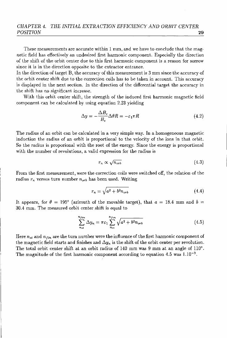
These measurements are accurate within 1 mm, and we have to conclude that the magnetic field has effectively an undesired first harmonie component. Especially the direction of the shift of the orbit center due to this first harmonie component is a reason for sorrow sirree it is in the direction opposite to the extrador entrance. In the direction of target B, the accuracy of this measurement is 3 mm sirree the accuracy of the orbit center shift due to the correction coils has to betaken in account. This accuracy is displayed in the next section. In the direction of the differential target the accuracy in the shift has no significant increase.
With this orbit center shift, the strength of the induced first harmonie magnetic field component can be calculated by using equation 2.23 yielding
( 4.2)
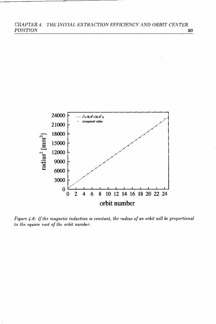
The radius of an orbit can be calculated in a very simple way. In a homogeneous magnetic induction the radius of an orbit is proportional to the velocity of the ions in that orbit. So the radius is proporional with the root of the energy. Sirree the energy is proportional with the number of revolutions, a valid expression for the radius is
rn ex vn:;b ( 4.3)
From the first measurement, were the correction coils were switched off, the relation of the radius rn versus turn number norb has been used. Writing
It appears, for () = 195° (azimuth of the movable target), that a
30.4 mm. The measured orbit center shift is equal to
nfin nfin
L D.yn = 7rêl L V a2 + b2norb
nst
( 4.4)
18.4 mm and b =
( 4.5)
Here nst and n Jin are the turn number were the in:fluence of the first harmonie component of the magnetic field starts and finishes and D.yn is the shift of the orbit center per revolution. The total orbit center shift at an orbit radius of 140 mm was 9 mm at an angle of 110°. The magnitude of the first harmonie component according to equation 4.5 was 1.10-3
.
CHAPTER 4. THE INITIAL EXTRACTION EFFICIENCY AND ORBIT CENTER POSITION 30
r--ol N
ê 1-...1
N 00
= ·~ "tj ro loo-I
24000
21000
18000
15000
12000
9000
6000
3000
0 0
- ~=18.42+30.42 n • measured value
2 4 6 8 10 12 14 16 18 20 22 24
orbit number
Figure 4. 6: Ij the magnetic induction is constant, the radius of an orbit will be proportional to the square root of the orbit number.
GRAPTER 4. THE INITIAL EXTRACTION EFFICIENCY AND ORBIT CENTER POSITION 31
Summary Due to a drift of the orbit center in the direction opposite to the extractor entrance! the infiuence of the fringing field is increased. This causes the beam to widen out thereby limiting the extraction efficency! since the aperture of the extractor is limited.
Chapter 5
The correction coils
5.1 Introduetion
From the measurements in the previous chapter it became clear that the orbit center is shifting in an undesired direction. The orbit center can he repositioned by the activation of the various correction coils. The vertical and radial influence of the various correction coils has been measured to see if the orbit center could he positioned at the geometrie center of the cyclotron.
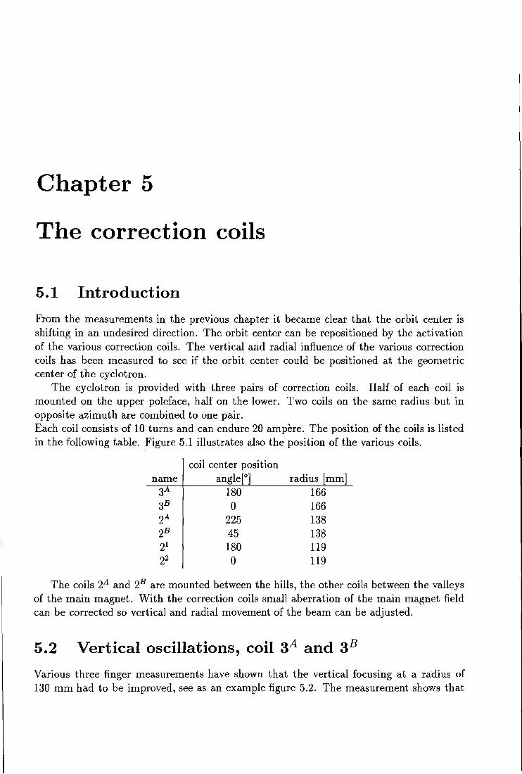
The cyclotron is provided with three pairs of correction coils. Half of each coil is mounted on the upper poleface, half on the lower. Two coils on the same radius but in opposite azimuthare combined to one pair. Each coil consists of 10 turns and can endure 20 ampère. The position of the coils is listed in the following table. Figure 5.1 illustrates also the position of the various coils.
coil center position name angle[0
] radius [mm] 3 180 166 3B 0 166 2A 225 138 2B 45 138 21 180 119 22 0 119
The coils 2A and 28 are mounted between the hills, the other coils between the valleys of the main magnet. With the correction coils small aberration of the main magnet field can he corrected so vertical and radial movement of the beam can he adjusted.
5.2 Vertical oscillations, coil 3A and 3B
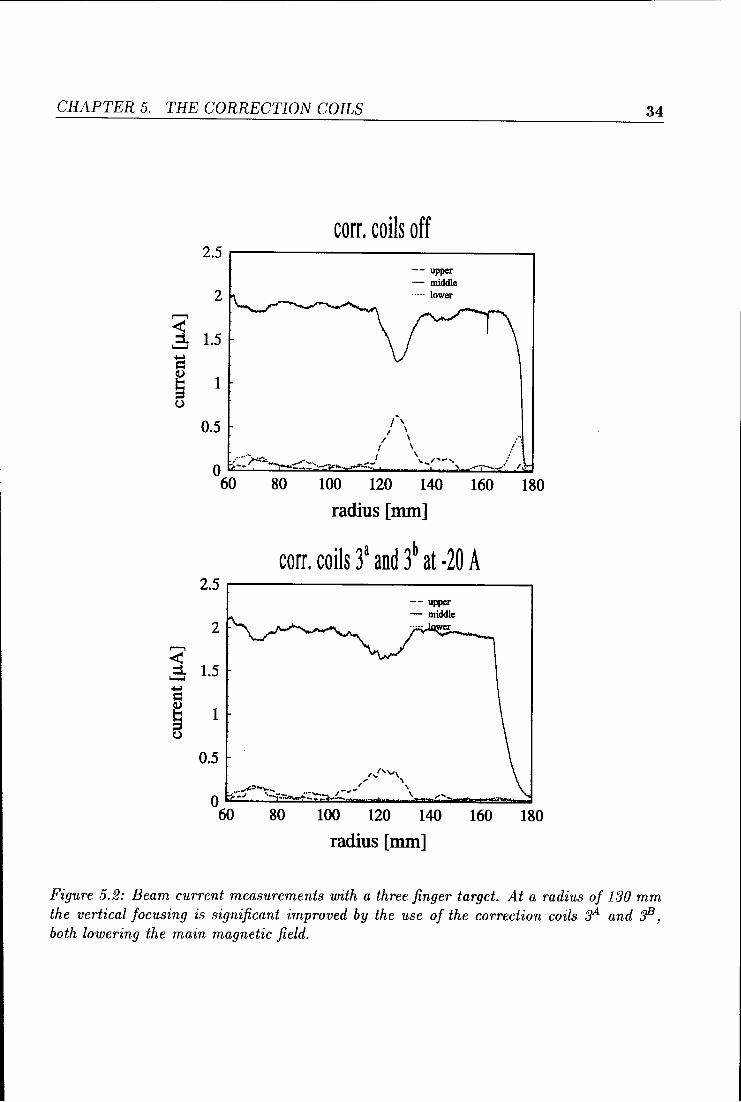
Various three finger measurements have shown that the vertical focusing at a radius of 130 mm had to he improved, see as an example figure 5.2. The measurement shows that
CHAPTER 5. THE CORRECTION COILS 33
dee
-20
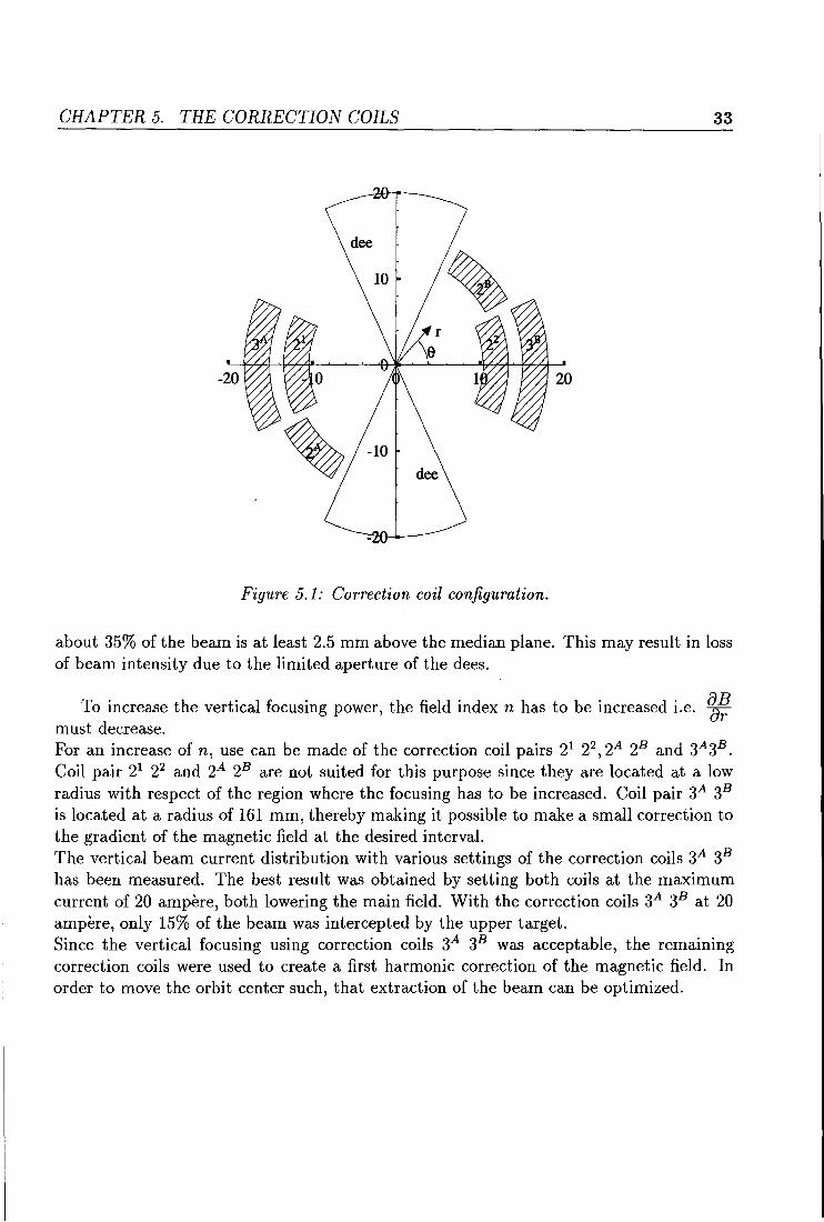
Figure 5.1: Correction coil configuration.
about 35% of the beam is at least 2.5 mm above the median plane. This may result in loss of beam intensity due to the limited aperture of the dees.
To increase the vertical focusing power, the field index n has to be increased i.e. ~~ must decrease. For an increase of n, use can be made of the correction coil pairs 21 22
, 2A 28 and 3A3B. Coil pair 21 22 and 2A 28 are not suited for this purpose sirree they are located at a low radius with respect of the region where the focusing has to be increased. Coil pair 3A 38
is located at a radius of 161 mm, thereby making it possible to make a small correction to the gradient of the magnetic field at the desired interval. The vertical beam current distribution with various settings of the correction coils 3A 38
has been measured. The best result was obtained by setting both coils at the maximum current of 20 ampère, both lowering the main field. With the correction coils 3A 38 at 20 ampère, only 15% of the beam was intercepted by the upper target. Sirree the vertical focusing using correction coils 3A 38 was acceptable, the remairring correction coils were used to create a first harmonie correction of the magnetic field. In order to move the orbit center such, that extraction of the beam can be optimized.
CHAPTER 5. THE CORRECTION COILS 34
corr. coils off 2.5
-- upper - middle
2 ..... lower
,.......,
1 1.5 ..........
= ~ 1 u
0.5 ~'' I \ I \ .~
I \ .. ··/ ..... •'j<-... _ I \ ... , ...... ,
0 ~-- ~ ' _-r-,........._,/ , .
60 80 100 120 140 160 180
radius [mm]
corr. coils 3a and 3b at -20 A 2.5
-- upper - middle
2 ,.......,
1 1.5 ..........
I 1 u
0.5
0 .;:;." ",
60 80 100 120 140 160 180
radius [mm]
Figure 5.2: Beam current measurements with a three finger target. At a radius of 130 mm the vertical focusing is significant improved by the use of the correction coils 3A and :JB, both lowering the main magnetic field.
GRAPTER 5. THE CORRECTION COILS 35
5.3 Orbit center shift, coil 21 22 and 2A 2B
By repositioning the orbit center, the last revolution can he positioned more appropriate at the extractor entrance in order to increase the extractor efficiency. The magnitude and direction of the orbit center shift due to activation of the correction coils has been measured at an orbit radius of 150 mm. This is close to the extractor radius but the fringing field is not yet effective. The orbit center shift has been determined by measuring the shift in orbit radial position, since this shift is related to the shift in orbit center. If an orbit center drifts into a certain direction ~s then, measured under an angle a, the orbit radial position shift ~r (in a first order approximation for ~s ~ r) equals
~r = scosa
To measure the drift in two directions, two targets have been used; the fixed integral target B and the moving differential target. The shift of an orbit in the direction of the differential target is equal to the shift in its peak position. In the direction of the fixed target B, the difference in the total number of revolutions, before being intercepted by this target, times the orbit separation is equal to the orbit center shift.
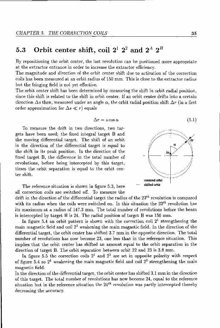
The reference situation is shown in figure 5.3, here all correction coils are switched off. To measure the
centered orbit
shifted orbit
(5.1)
drift in the direction of the differential target the radius of the 23th revolution is compared with its radius when the coils were switched on. In this situation the 23th revolution has its maximum at a radius of 147.3 mm. The total number of revolutions before the beam is intercepted by target B is 24. The radial position of target B was 150 mm.
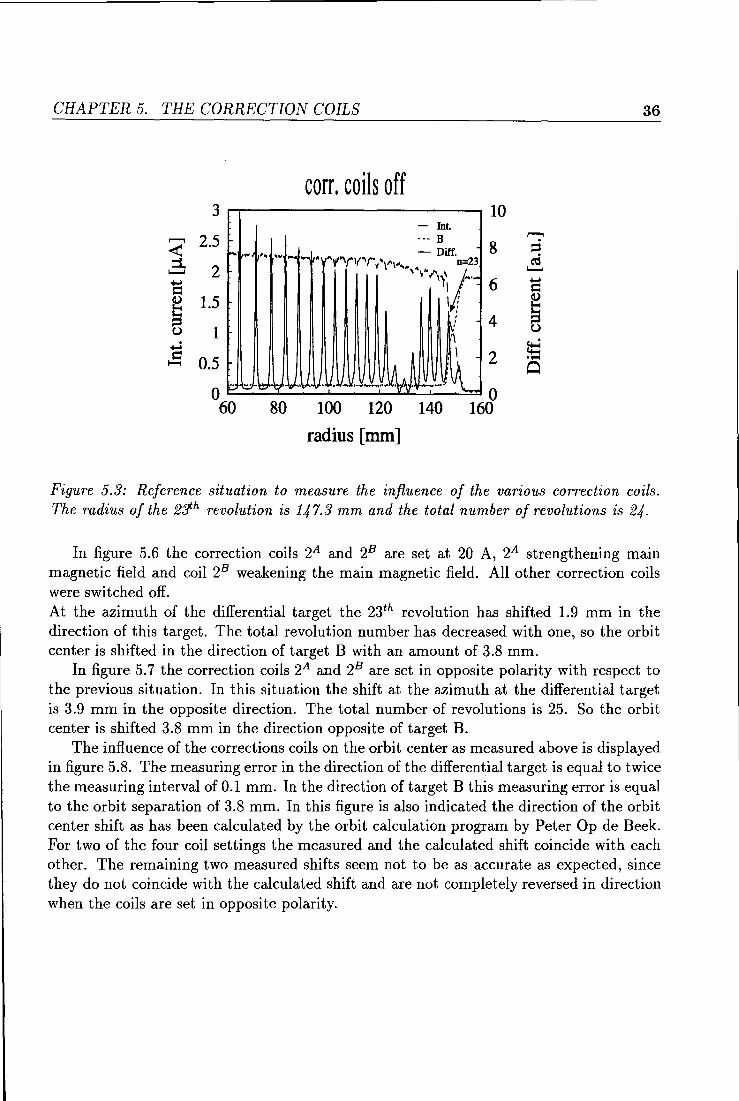
In figure 5.4 an orbit pattem is shown with the correction coil 21 strengtherring the main magnetic field and coil 22 weakening the main magnetic field. In the direction of the differential target, the orbit center has shifted 3. 7 mm in the opposite direction. The total number of revolutions has now become 23, one less than in the reference situation. This implies that the orbit center has shifted an amount equal to the orbit separation in the direction of target B. The orbit separation between orbit 22 and 23 is 3.8 mm.
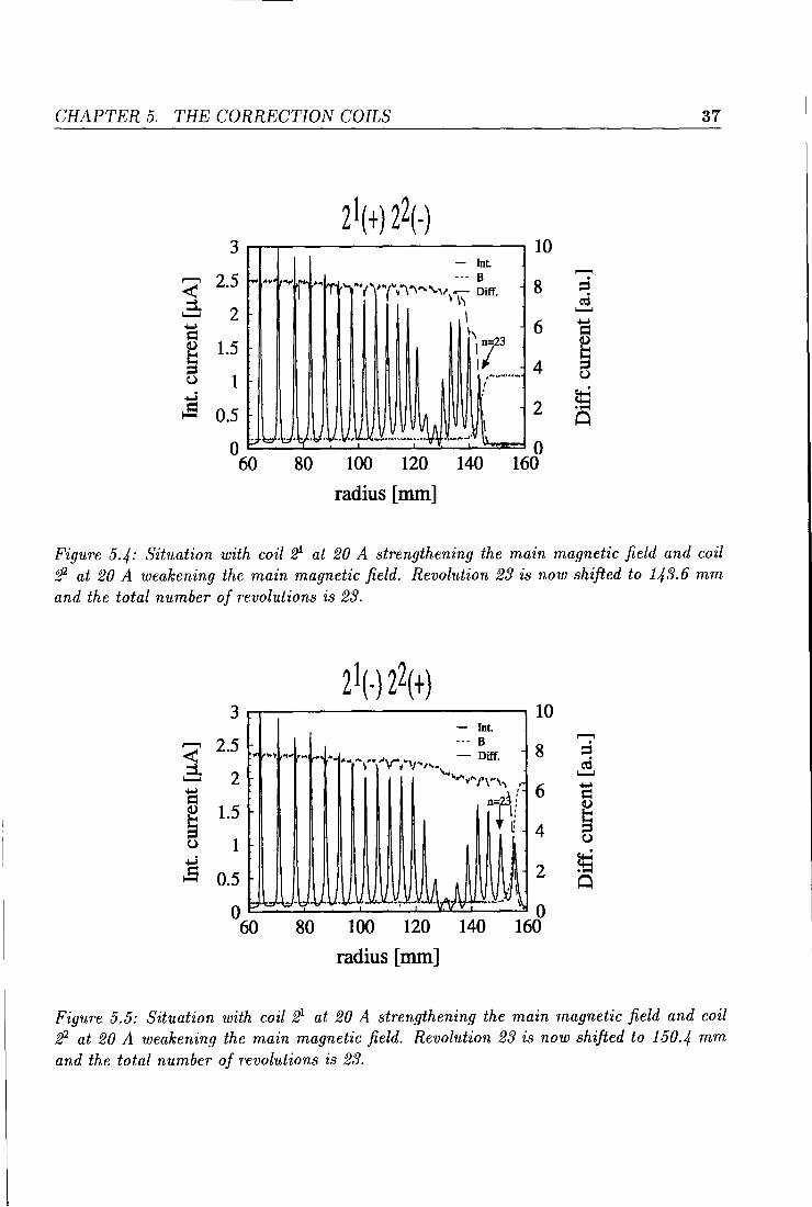
In figure 5.5 the correction coils 21 and 22 are set in opposite polarity with respect of figure 5.4 so 21 weakening the main magnetic field and coil 22 strengtherring the main magnetic field. In the direction of the differential target, the orbit center has shifted 3.1 mm in the direction of this target. The total number of revolutions has now become 24, equal to the reference situation but in the reference situation the 24th revolution was partly intercepted thereby decreasing the accuracy.
CHAPTER 5. THE CORRECTION COILS
corr. coils off 3 r--r-------------. 10
- Int
r--, 2.5 1
--- B
'---'
! ()
:s
2
1.5
1
0.5
... , ...
~
p=·bll;l·~"·"· .•• __ .14J __ :l 2
o.__ __ _,__ ____ __.____._.....___.L..L-_,__...........;=o
60 80 100 120 140 160
radius [mm]
36
Figure 5.3: Reference situation to measure the infiuence of the various correction coils. The radius of the 2:Jh revolution is 147.3 mm and the total number of revolutions is 24.
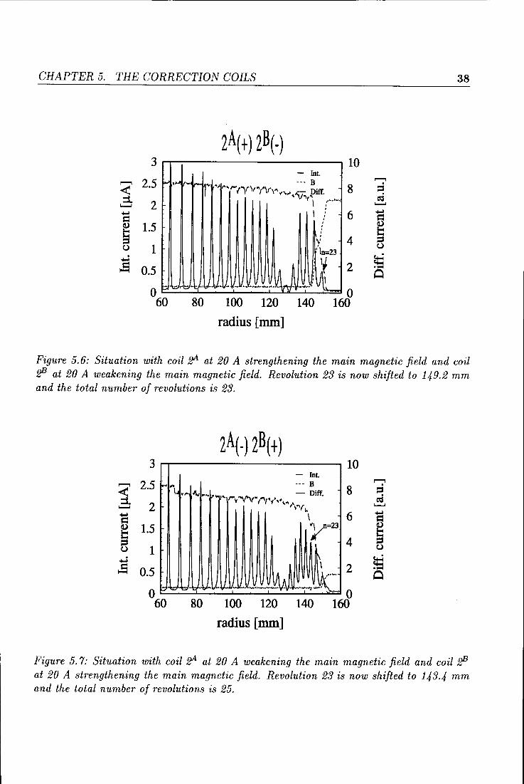
In figure 5.6 the correction coils 2A and 28 are set at 20 A, 2A strengthening main magnetic field and coil 28 weakening the main magnetic field. All other correction coils were switched off. At the azimuth of the differential target the 23th revolution has shifted 1.9 mm in the direction of this target. The total revolution number has decreased with one, so the orbit center is shifted in the direction of target B with an amount of 3.8 mm.
In figure 5. 7 the correction coils 2A and 28 are set in opposite polarity with respect to the previous situation. In this situation the shift at the azimuth at the differential target is 3.9 mm in the opposite direction. The total number of revolutions is 25. So the orbit center is shifted 3.8 mm in the direction opposite of target B.
The influence of the corrections coils on the orbit center as measured above is displayed in figure 5.8. The measuring error in the direction of the differential target is equal to twice the measuring interval of 0.1 mm. In the direction of target B this measuring error is equal to the orbit separation of 3.8 mm. In this figure is also indicated the direction of the orbit center shift as has been calculated by the orbit calculation program by Peter Op de Beek. For two of the four coil settings the measured and the calculated shift coincide with each other. The remaining two measured shifts seem not to be as accurate as expected, since they do not coincide with the calculated shift and are not completely reversed in direction when the coils are set in opposite polarity.
CHAPTER 5. THE CORRECTION COILS
zl(+) z2(-) 3 ........r--r--------------, 10
1 2.5 .......... 2
1.5
1
8
6
4
~ 2
0.~ t::::' :...::"-='::._·1::1::::.· ·~tt~·IJ~·.V:;:_·.:_:II··...i......:.:~-:.:..··-···-...:..-L..."~~-·:.:.:.-,......LJ'_.!\\~=:1 0 60 80 100 120 140 160
radius [mm]
37
Figure 5.4: Situation with coil 21 at 20 A strengthening the main magnetic field and coil f!2 at 20 A weakening the main magnetic field. Revolution 23 is now shifted to 143.6 mm and the total number of revolutions is 23.
zl(-) z2(+) 3 ........r--------------, 10
,........, 2.5 1 .......... 2
I 1.~ ~ 0.5 I A A ·' 2
O ~..._.::;:..::.~-\;?~V:::::V;::·-~.A~·v·::·"'~~=: .. \/~ .. \lz: ILA!tvJiï::::::::-·::Y~:_:XJ~l~ O 60 80 100 120 140 160
radius [mm]
,........,
::i cd ..........
Figure 5.5: Situation with coil 21 at 20 A strengthening the main magnetic field and coil f!2 at 20 A weakening the main magnetic field. Revolution 23 is now shifted to 150.4 mm and the total number of revolutions is 23.
CHAPTER 5. THE CORRECTION COILS 38
zA(+) zB(-) 3 10
- Int
2.5 --- B ,........., ,........., ~ ... '"'Ir'"' ~~ 8 ;:i < ·~ ,.., ,... ('l,f\t '"/\ry' _ Diff
"'""'•"V"' ~ . ~ :i r I :··"" ~ 2 ~
I ' = .... ' 6 ' = ' '
~ ~ 1.5 ' ' ' ' 4 \' C,) 1 :\n=23
C,)
:s 0.5 u i~ 2 ~ : I 0
0 ·\:::,11 t:J•'!:.(••Vo ·l.l·V· .. ll. ••••·--· .w .. .' ~
0 60 80 100 120 140 160
radius [mm]
Figure 5. 6: Situation with coil ft1A at 20 A strengthening the ma in magnetic field and coil f!3 at 20 A weakening the main magnetic field. Revolution 23 is now shifted to 149.2 mm and the total number of revolutions is 23.
zA(-) zB( +) 3 ,.........-------------, 10
- Int .. -• --- B
\ .... ~~.. - Diff. 8 ,. ..... rv•vv·t't•l·· '"'-\•y \.
\ 6 y=23 4
,........., 2.5 1 ~ 2
I 1.~ :s 0.5
O - 1:::> b·t', '~>' .v .. .IJ l/. M_ __ lW .. ~i- 2
0 120 140 160 60 80 100
radius [mm]
Figure 5. 7: Situation with coil ft1A at 20 A weakening the main magnetic field and coil f!3 at 20 A strengthening the main magnetic field. Revolution 23 is now shifted to 143.4 mm and the total number of revolutions is 25.
CHAPTER 5. THE CORRECTION COILS
-10 -5
y 10
[mm]
' -10
39
5 10 ')L x [mm]
T(-) 28(+)
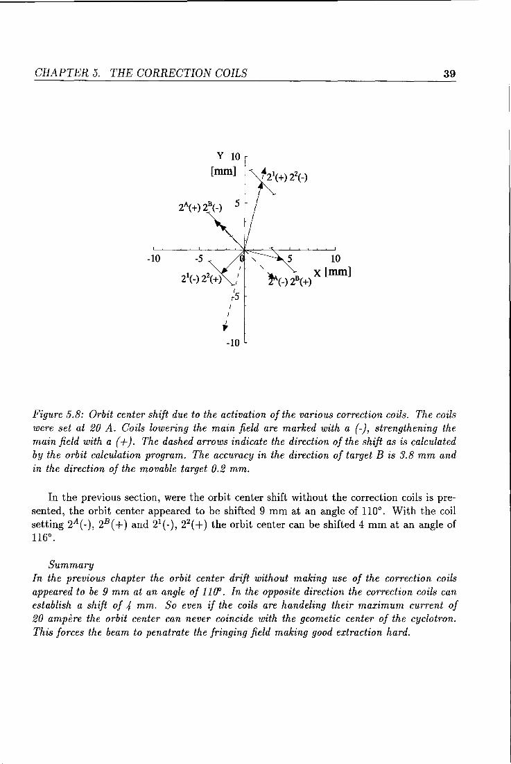
Figure 5.8: Orbit center shift due to the activation of the various correction coils. The coils were set at 20 A. Coils lowering the main field are marked with a (-), strengthening the main field with a ( +). The dashed arrows indicate the direction of the shift as is calculated by the orbit calculation program. The accuracy in the direction of target B is 3.8 mm and in the direction of the movable target 0.2 mm.
In the previous section, were the orbit center shift without the correction coils is presented, the orbit center appeared to he shifted 9 mm at an angle of 110°. With the coil setting 2A (-), 2B ( +) and 21 (-), 22 ( +) the orbit center can be shifted 4 mm at an angle of 116°.
Summary In the previous chapter the orbit center drift without making use of the correction coils appeared to be 9 mm at an angle of 1100. In the opposite direction the correction coils can establish a shift of 4 mm. So even iJ the coils are handeling their maximum current of 20 ampère the orbit center can never coincide with the geometic center of the cyclotron. This forces the beam to penatrate the fringing field making good extraction hard.
Chapter 6
Increasing the extraction efficiency
6.1 Introduetion
Since the orbit center can not be positioned correctly due tothelimits of excitation of the correction coils, alterations had to bemadein the main magnetic field. The only possibility to do so was repositioning of the correction slabs on each side of the polefaces. The result of repositioning of the slabs at the orbit center is displayed in the second section of this chapter. In the third section is shown how the extraction efficiency was further increased by placing the extractor at a lower radius.
6.2 Repositioning the orbit center
Each pole face is provided with six small correction slabs for trimming the magnetic field. In the past, all eight valleys were provided with two slabs each, which at that time seemed best for isochronism. Later on, the slabs in the valley where the extractor is positioned as well as in the opposite valley have been removed to increase the vertical focusing power. This offered the possibility for asymmetrical positioning of the remaining correction slabs in view of correct positioning of the orbit center. Asymmetrical placing of the correction slabs can compensate for undesired first harmonie components. Repositioning of the orbit center was clone by replacing the correction slabs from the negative y-coordinate to the positive x-coordinate (in the extractor valley).
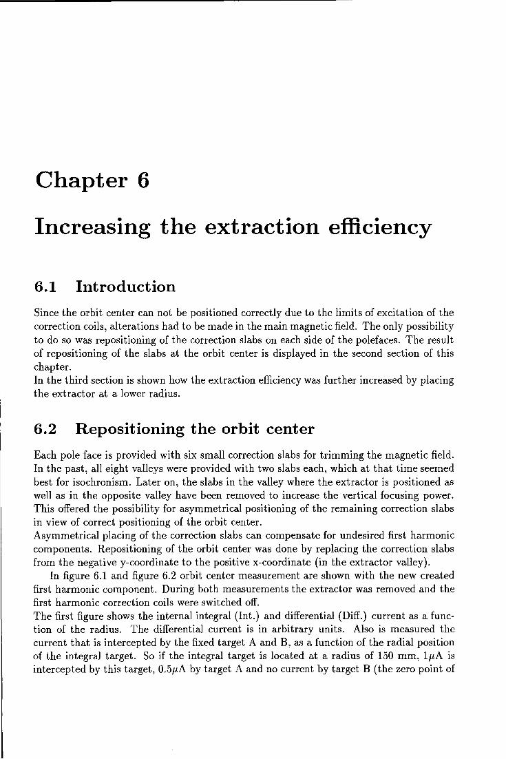
In figure 6.1 and figure 6.2 orbit center measurement are shown with the new created first harmonie component. During both measurements the extractor was removed and the first harmonie correction coils were switched off. The first figure shows the internal integral (Int.) and differential (Diff.) current as a function of the radius. The differential current is in arbitrary units. Also is measured the current that is intercepted by the fixed target A and B, as a function of the radial position of the integral target. So if the integral target is located at a radius of 150 mm, 1pA is intercepted by this target, 0.5pA by target A and no current by target B (the zero point of
GRAPTER 6. INCREASING THE EXTRACTION EFFICIENCY
,.......,
1 .......... ...... s:::::
~ u
........
~
3
2.5
2 1---
1.5
1
0.5
0 60
....
RA=160 mm RB=160 mm
·-
10 -- Int ..... A
-·- B 8 - Diff.
--[-.oo .. ..,~ ·-~ i"'t"~''t'r'/' I V\ I
6 ~
I
~ I
I . . . --i--.i'l
4
2
80 100 120 140 0
160
radius [mm]
41
,......., ::s cd ..........
= ~ u
~ 0
Figure 6.1: Beam measurement with two fixed targets (A and B), one moving integral target (Int.) and a moving differential target (Diff.). Replacing small correction slabs induces a new first harmonie magnetic component that pushes the orbit center in the direction of the extrador entrance. In the former situation the orbit center was shifted 8 mm in the opposite direction. During the measurement the first harmonie correction coils were swiched off.
RExtr.=160 mm 2.5 10
-- Int ,......., ..... Ext ,.......,
< 2 - Diff 8 ::s r-.t.-..... ... "''""('(l''li"V'-•• . cd :::1. 1 I ~""/\fi/IJ.~ .......... .......... { \ ...... ...... 1.5 6 s::::: s::::: I
I
~ a) I ,
.,....
s 1 I f 4 I ! u u 1/
:s 0.5 ~~ 2 ~ 0
0 '-- ~.,..uu y V 11 11
0 60 80 100 120 140 160
radius [mm]
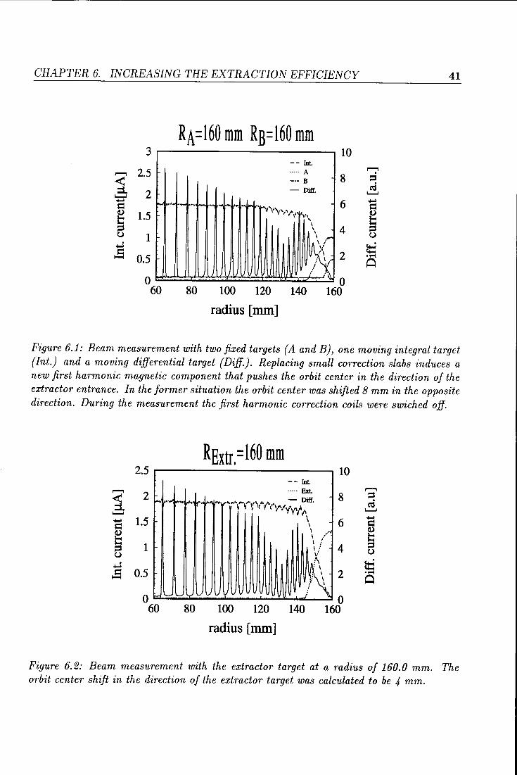
Figure 6.2: Beam measurement with the extractor target at a radius of 160.0 mm. The orbit center shift in the direction of the extractor target was calculated to be 4 mm.
CHAPTER 6. INCREASING THE EXTRACTION EFFICIENCY 42
the current of target Bis set somewhat above zero). From this figure and by comparison with figure 4.4 it is obvious that the orbit center is pushed towards target A, since targets A and B are located at the same radius and target A is intercepting almost the whole beam. So the previous measured shift of the orbit center in the opposite direction of the extrador is replaced by a reversed shift. The exact amount of shift towards target A is hard to calculate since the beam is not well centered between the two targets A and B but must he at least about 5 mm. The radial divergence due to the influence of the fringing field is clear to see since it takes the movable integral target an interval of 10 mm to let the current on target A reach its final value. For figure 6.2 the extrador target was set at a radius of 160 mm, leaving target A and B at the same radius. About 80% of the internal beam was intercepted by this target. At a radius of 150 mm, the current is equally divided between the integral target and the extrador target. Subtrading this radius by the actual position of the extrador target will give two times the orbit center displacement. Here has to he taken in account the gain in radius due to the acceleration over half a revolution. This shift of the orbit center was calculated to he 4 mm. Taking in account the shift measured before, we conclude that repositioning of the four correction slabs resulted in an orbit center shift of at least 13 mm. From the measurements one may conclude also that the undesired first harmonie component is compensated and a new first harmonie component is created that pushes the orbit center towards the extractor.
6.3 The new extractor position
In the past the extrador was located at a radius of 168 mm, making the orbit behaviour very sensitive for incorrect eentering and fringing field effects. From the previous measurement it is clear that the influence of the fringing field at a radius of 160 mm was such that several orbits were intercepted by the fixed target A. To overcome this problem, the extrador had to he located at a lower radius. Because of the fact that the extrador is located in a valley, the range it can shift is limited. It will get stuck between the two hills at each side of the extractor. Without major adjustments it could reach a radius of 158 mm. To do so, a new flange for the extrador was made.
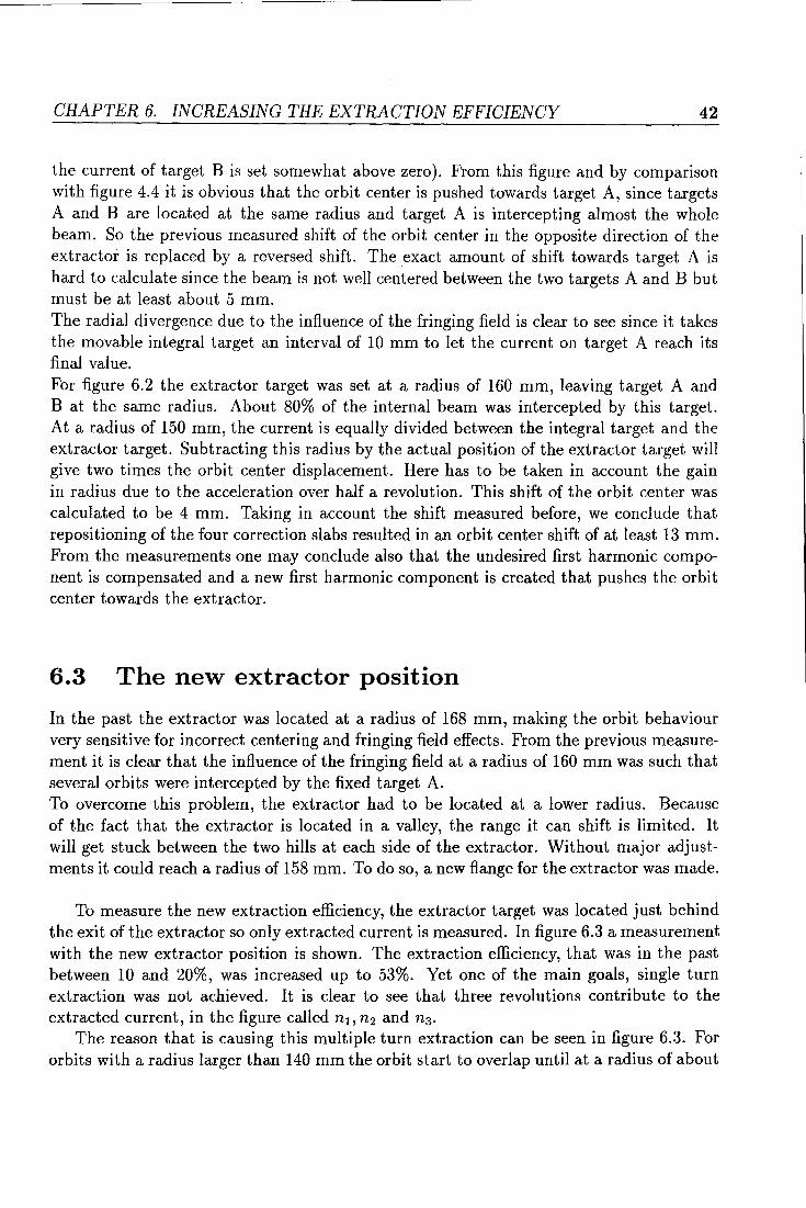
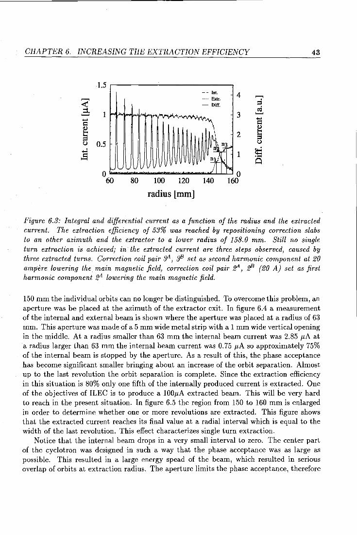
To measure the new extraction efficiency, the extrador target was located just behind the exit of the extrador so only extracted current is measured. In figure 6.3 a measurement with the new extrador position is shown. The extraction efficiency, that was in the past between 10 and 20%, was increased up to 53%. Yet one of the main goals, single turn extraction was not achieved. It is clear to see that three revolutions contribute to the extracted current, in the figure called n1 , n2 and n3 •
The reason that is causing this multiple turn extraction can he seen in figure 6.3. For orbits with a radius larger than 140 mm the orbit start to overlap until at a radius of about
CHAPTER 6. INCREASING THE EXTRACTION EFFICIENCY 43
1.5 ,....-------------.. -- Int ----- Extr. 4 - Diff.
Figure 6.3: Integral and differential current as a function of the radius and the extracted current. The extraction efficiency of 53% was reached by repositioning correction slabs to an other azimuth and the extractor to a lower radius of 158.0 mm. Still no single turn extraction is achieved; in the extracted current are three steps observed! caused by three extracted turns. Correction coil pair 3A! :JE set as second harmonie component at 20 ampère lowering the main magnetic field! correction coil pair ~! ff3 (20 A) set as first harmonie component ~ lowering the main magnetic field.
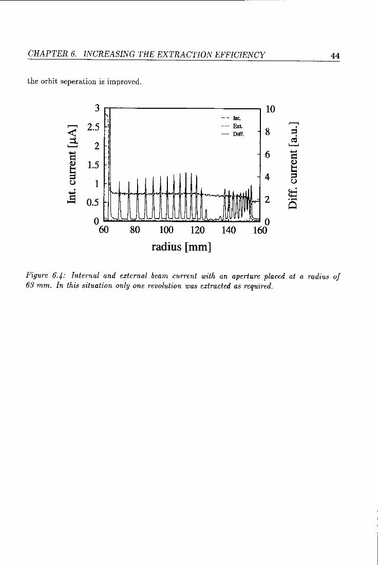
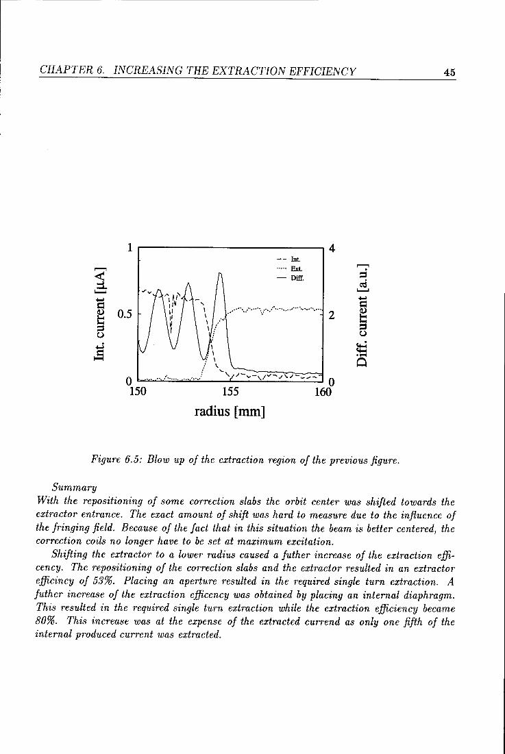
150 mm the individual orbits can no longer be distinguished. To overcome this problem, an aperture was be placed at the azimuthof the extrador exit. In figure 6.4 a measurement of the internaland externalbeamis shown where the aperture was placed at a radius of 63 mm. This aperture was made of a 5 mm wide metal strip with a 1 mm wide vertical opening in the middle. At a radius smaller than 63 mm the internal beam current was 2.85 11A at a radius larger than 63 mm the internal beam current was 0. 75 11A so approximately 75% of the internal beam is stopped by the aperture. As a result of this, the phase acceptance has become significant smaller bringing about an increase of the orbit separation. Almost up to the last revolution the orbit separation is complete. Since the extraction efficiency in this situation is 80% only one fifth of the internally produced current is extracted. One of the objectives of ILEC is to produce a 10011A extracted beam. This will he very hard to reach in the present situation. In figure 6.5 the region from 150 to 160 mm is enlarged in order to determine whether one or more revolutions are extracted. This figure shows that the extracted current reaches its final value at a radial interval which is equal to the width of the last revolution. This effect characterizes single turn extraction.
Notice that the internal beam drops in a very smallinterval to zero. The center part of the cyclotron was designed in such a way that the phase acceptance was as large as possible. This resulted in a large energy spead of the beam, which resulted in serious overlap of orbits at extraction radius. The aperture limits the phase acceptance, therefore
CHAPTER 6. INCREASING THE EXTRACTION EFFICIENCY
the orbit seperation is improved.
3 10 r-. -- Int I
r--"'1 2.5 < I ----- Ext I - Diff. 8
:i. 2 1.........1
~ = 6 Cl.) 1.5 ~ u 1
~ 0.5 i" .... ..,. f--- I- ,. 4 ... ~ ... l a~ll "'"'•••4fM'tl
IHHIII.II
4
2
0 60
- '- '- '- L 1/~~~l 0
160 80 100 120 140
radius [mm]
44
r--"'1 . = C\Ï
1.........1
~ = ~ u
~ 0
Figure 6.4: Internal and external beam current with an aperture placed at a radius of 63 mm. In this situation only one revolution was extracted as required.
CHAPTER 6. INCREASING THE EXTRACTION EFFICIENCY 45
1 r-----------------------~4 -- Int.
~
1 ----- Ext. - Diff.
~
...... s:l
~ 0.5 2
u
;$ 0 ~- ....... ;.
'--,1/-Y-,/v~/~/-~~- 0
150 155 160
radius [mm]
Figure 6.5: Blow up of the extraction region of the previous figure.
Summary With the repositioning of some correction slabs the orbit center was shifted towards the extractor entrance. The exact amount of shift was hard to measure due to the influence of the fringing field. Because of the fact that in this situation the beam is better centered, the correction coils no longer have to be set at maximum excitation.
Shifting the extractor to a lower radius caused a futher increase of the extraction efficency. The repositioning of the correction slabs and the extractor resulted in an extractor efficincy of 53%. Placing an aperture resulted in the required single turn extraction. A futher increase of the extraction efficency was obtained by placing an internal diaphragm. This resulted in the required single turn extraction while the extraction efficiency became 80%. This increase was at the expense of the extracted currend as only one fifth of the internal produced current was extracted.
Chapter 7
Conclusions, recommendations
From the orbit centre measurements it appeared that a shift of the orbit centre of several millimeters can cause an increase of about 40% in the extraction efficiency. The consequence of this is that the position of the orbit centre and the range that the correction coils can shift it, has to be well known and adjusted correctly.
The present situation is such that the orbit centre position can not be measured in an easy way. It takes several measurements to determine the orbit centre position and for each measurement the vacuumchamber has to be opened. This effects the accuracy of the measurements. If in the future more measurements with a higher accuracy have to be performed, it would be desirabie to have a second movable differential target at an azimuth perpendicular to the present one. Apart from this a more complete computer controlled measuring system should be constructed that offers a higher flexibility than the present used.

Bibliography
[1] Schulte, W.M., Thesis, Eindhoven Univ. of Technology, 1978
[2] Bennet, J.R.J., Proc. 1st Int. Conf. on loon Sources, Saclay 1969
[3] Van Nieuwland, J.M., Thesis, Eindhoven Univ. of Technology, 1972
[4] de Regt, R.J.L.J., Graduation report, Eindhoven Univ. of Technology, 1986, vdf/nk 85-22
[5] Jansen, Ben, Report of practical work at the EUT, 1985, vdf/nk 85-39
[6] Schlangen, Jos, Report of practicalworkat the EUT, 1984, vdf/nk 84-03
[7] Steeman, P.A.M., Graduation report, Eindhoven Univ. of Technology, 1985, vdf/nk 85-22
[8] Hagedoorn, H.L. and Verster, N.F., Nucl.lnstr. Meth 18, 19 (1962) 201
[9] Kleeven, W.J.G.M., Thesis, Eindhoven Univ. of Technology, 1988
[10] Theeuwen, S.J.C.H., Report of practical work at the EUT, 1992, vdf/nk 92-19
[11] Hagedoorn, H.L. and Kleeven, W.J.G.M., CernAcc.School Fourth Gen. Acc. Physics course. 1990
Appendix A
Emittance measuring system
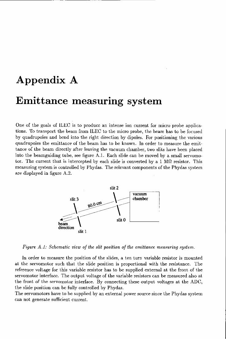
One of the goals of ILEC is to produce an intense ion current for micro probe applications. To transport the beam from ILEC to the micro probe, the beam has to be focused by quadrupoles and bend into the right direction by dipoles. For positioning the various quadrupoles the emittance of the beam has to be known. In order to measure the emittance of the beam directly after leaving the vacuum chamber, two slits have been placed into the beamguiding tube, see figure A.l. Each slide can be moved by a small servomotor. The current that is intercepted by each slide is converted by a 1 Mn resistor. This measuring system is controlled by Phydas. The relevant components of the Phydas system are displayed in figure A.2.
slit 2
slit3 ~ 1~~
-~\~ ..---____.-- slit 0 beam direction
slit 1
vacuum chamber
Figure A .1: Schematic view of the slit position of the emittance measuring system.
In order to measure the position of the slides, a ten turn variabie resistor is mounted at the servomotor such that the slide position is proportional with the resistance. The reference voltage for this variabie resistor has to be supplied external at the front of the servomotor interface. The output voltage of the variabie resistors can be measured also at the front of the servomotor interface. By connecting these output voltages at the ADC, the slide position can be fully controlled by Phydas. The servomotors have to be supplied by an external power souree sirree the Phydas system can not generate sufficient current.
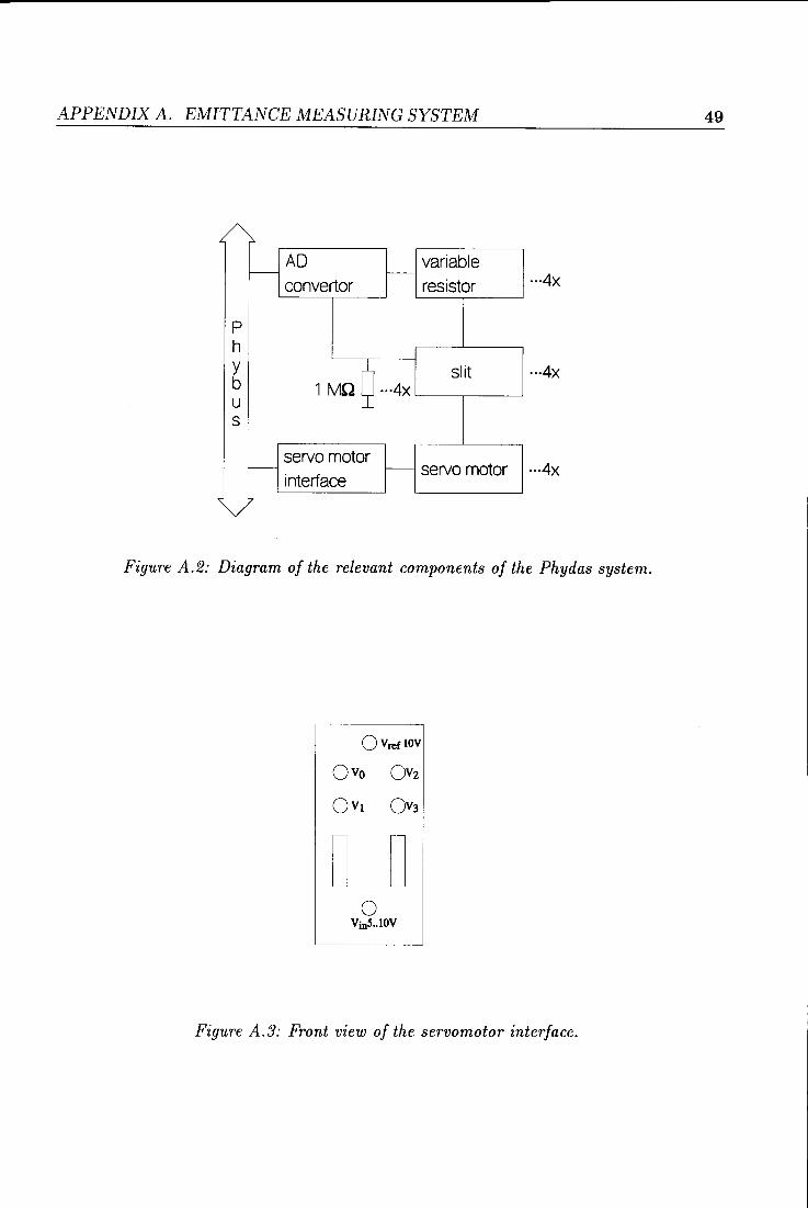
APPENDIX A. EMITTANCE MEASURING SYSTEM 49
r-AD variabie
f-- 1---
convertor resistor ···4X
p h y
1 MQ Q ···4x slit
b u s
servomotor - 1--- servomotor
interface
' 7
Figure A.2: Diagram of the relevant components of the Phydas system.
ÜVreflOV
ll D 0
VïnS .. lOV
Figure A.3: Front view of the servomotor interface.
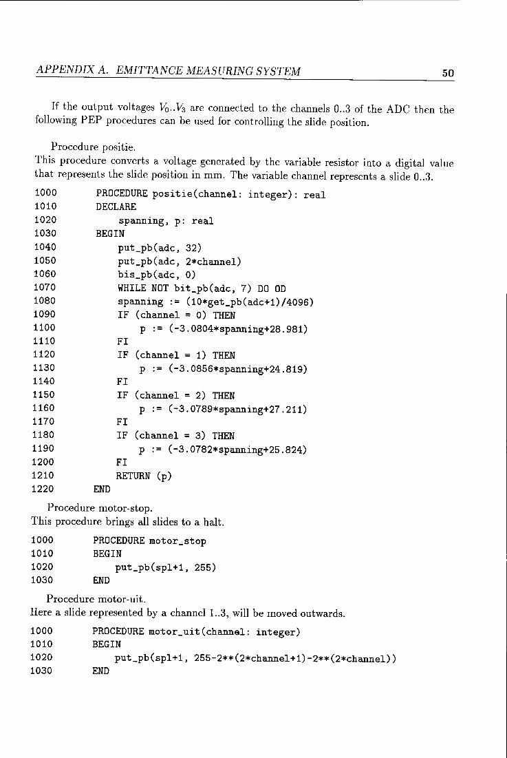
APPENDIX A. EMITTANCE MEASURING SYSTEM 50
If the output voltages Va .. V3 are connected to the channels 0 .. 3 of the ADC then the following PEP procedures can be used for cantrolling the slide position.
Procedure positie. This procedure converts a voltage generated by the variabie resistor into a digital value that represents the slide position in mm. The variabie channel represents a slide 0 .. 3.
1000 PROCEDURE positie(channel: integer): real 1010 DECLARE 1020 spanning, p: real 1030 BEGIN 1040 put_pb(adc, 32) 1050 put_pb(adc, 2*channel) 1060 bis_pb(adc, 0) 1070 WHILE NOT bit_pb(adc, 7) DO OD 1080 spanning := (10*get_pb(adc+1)/4096) 1090 IF (channel = 0) THEN 1100 p := (-3.0804*spanning+28.981) 1110 FI 1120 IF (channel = 1) THEN 1130 p := (-3.0856*spanning+24.819) 1140 FI 1150 IF (channel = 2) THEN 1160 p := (-3.0789*spanning+27.211) 1170 FI 1180 IF (channel = 3) THEN 1190 p := (-3.0782*spanning+25.824) 1200 FI 1210 RETURN (p) 1220 END
Procedure motor-stop. This procedure brings all slides to a halt.
1000 PROCEDURE motor_stop 1010 BEGIN 1020 put_pb(spl+1, 255) 1030 END
Procedure motor-uit. Here a slide represented by a channel 1..3, will be moved outwards.
1000 PROCEDURE motor_uit(channel: integer) 1010 BEGIN 1020 put_pb(spl+1, 255-2**(2*channel+1)-2**(2*channel)) 1030 END
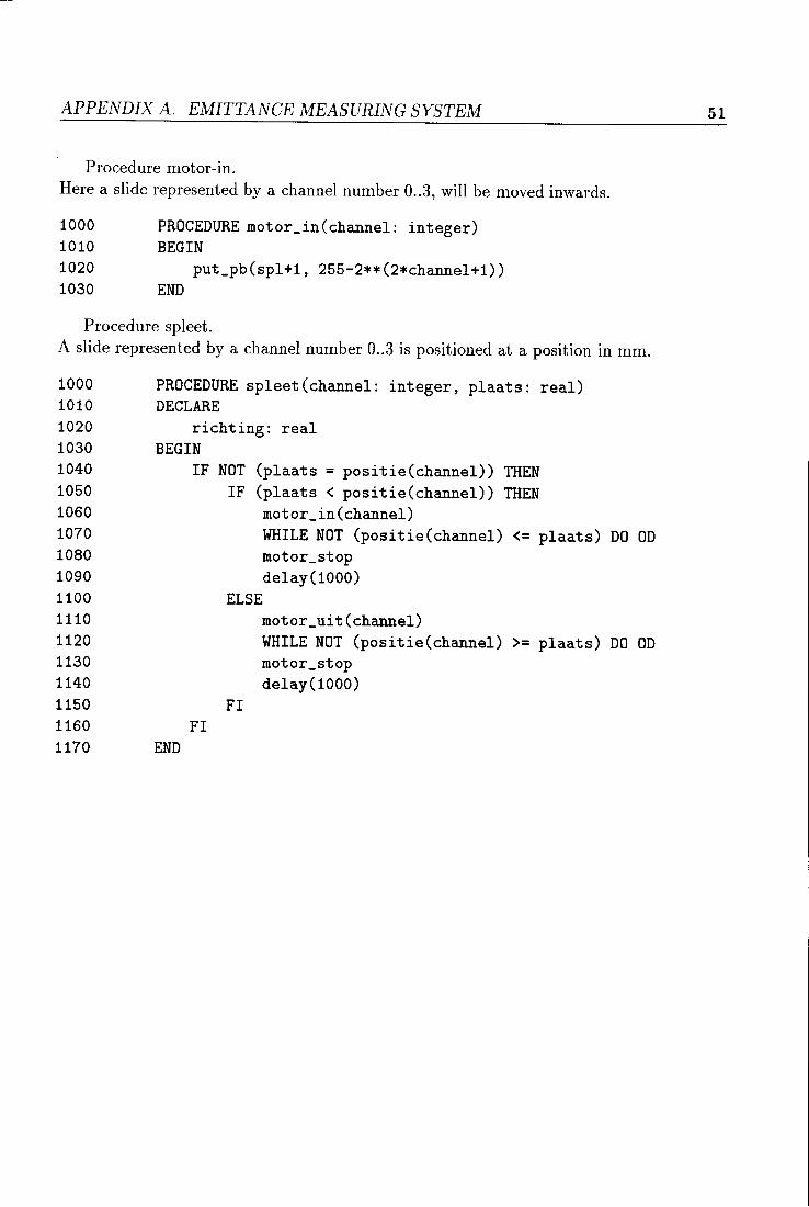
APPENDIX A. EMITTANCE MEASURING SYSTEM
Procedure motor-in. Here a slide represented by a channel number 0 .. 3, will be moved inwards.
1000 PROCEDURE motor_in(channel: integer) 1010 BEGIN
1020 put_pb(spl+1, 255-2**(2*channel+1)) 1030 END
Procedure spleet. A slide represented by a channel number 0 .. 3 is positioned at a position in mm.
1000 PROCEDURE spleet(channel: integer, plaats: real) 1010 DECLARE 1020 richting: real 1030 BEGIN 1040 1050 1060 1070
IF NOT (plaats = positie(channel)) THEN IF (plaats < positie(channel)) THEN
motor_in(channel) WHILE NOT (positie(channel) <= plaats) DO OD
1080 motor_stop 1090 delay(1000) 1100 ELSE 1110 motor_uit(channel) 1120 WHILE NOT (positie(channel) >= plaats) DO OD 1130 motor_stop 1140 delay(1000) 1150 FI 1160 FI 1170 END
51
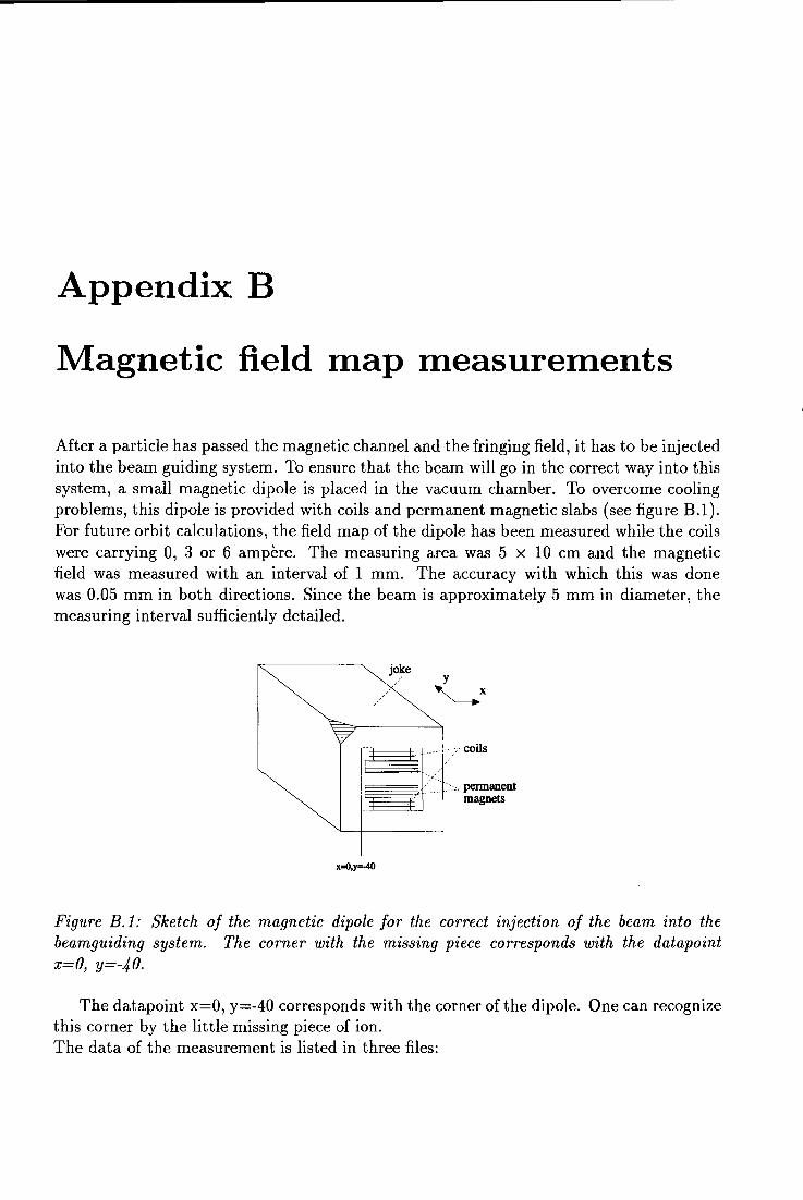
Appendix B
Magnetic field map measurements
After a partiele has passed the magnetic channel and the fringing field, it has to he injected into the beam guiding system. To ensure that the beam will go in the correct way into this system, a small magnetic dipole is placed in the vacuum chamber. To overcome cooling problems, this dipole is provided with coils and permanent magnetic slabs (see figure B.1 ). For future orbit calculations, the field map of the dipole has been measured while the coils were carrying 0, 3 or 6 ampère. The measuring area was 5 x 10 cm and the magnetic field was measured with an interval of 1 mm. The accuracy with which this was clone was 0.05 mm in both directions. Since the beam is approximately 5 mm in diameter, the measuring interval suffi.ciently detailed.
joke y
'-__.x
x=O,y:-40
coils
permanent magnets
Figure B.J: Sketch of the magnetic dipole for the correct injection of the beam into the beamguiding system. The corner with the missing piece corresponds with the datapoint x=O, y=-40.
The datapoint x=O, y=-40 corresponds with the corner of the dipole. One can recognize this corner by the little missing piece of ion. The data of the measurement is listed in three files:
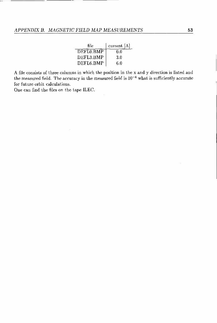
APPENDIX B. MAGNETIC FIELD MAP MEASUREMENTS
file DEFLO.BMP DEFL3.BMP DEFL6.BMP
current [A] 0.0 3.0 6.0
53
A file consists of three columns in which the position in the x and y direction is listed and the measured field. The accuracy in the measured field is 10-4 what is sufficiently accurate for future orbit calculations. One can find the files on the tape ILEC.
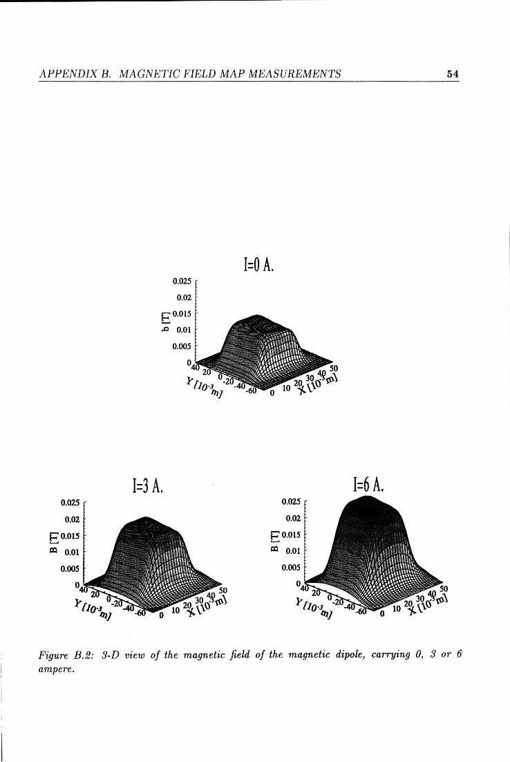
APPENDIX B. MAGNETIC FIELD MAP MEASUREMENTS
0.025
0.02
~0.015 '-'
lXI 0.01
0.005
0
0.025
0.02 .
~ 0.015 '-'
.r:J O.ot
0.005
0
1=3 A.
50
20 30~{(\\ 0 10 i.\~
I=O A.
50
20 30~{(\\ 0 10 i.\~
0.025
0.02
E o.o15
lXI 0.01
0.005
0
54
1=6 A.
50
20 30~{(\\ 0 10 i.\~
Figure B.2: 3-D view of the magnetic field of the magnetic dipole, carrying 0, 3 or 6 ampere.