Beam Clamps
20
Beam clamps offered in this section are designed to provide attachment of hanger rods to structural members without drilling or welding. A wide range of types and sizes are available for various applications. Materials Carbon Steel, Malleable Iron and Forged Steel are used in the manufacturing of beam clamps and accessories. Stainless steel and other materials are available. Finishes The standard finishes for mechanical supports are plain steel (oil coated) sometimes referred to as black and Electro-Galvanized Zinc (ASTM B633 SC3). Hot-Dip Galvanized After Fabrication (ASTM A123), Red Primer, Plastic Coating and DURA GREEN ™ . Other special coatings are available upon request. Note: Due to the design of some products, (threads, connecting hardware, swivels, etc.) items may or may not be uniformly coated with special finishes. In some cases, the hanger itself may be coated, however, the hardware may be supplied Electro-Plated, copper plated, or in stainless steel. Recommended Set screw Torque (unless otherwise specified) 1 /4”-20 3 /8”-16 1 /2”-13 5 /8”-11 3 /4”-10 4 ft/lbs (5 Nm) 5 ft/lbs (7 Nm) 11 ft/lbs (15 Nm) 21 ft/lbs (28 Nm) 34 ft/lbs (46 Nm) Over torqued set screws will damage beam clamps in this section. We are aware that torque wrenches are not used or not available in many instances. In the absence of a torque wrench, the set screw should be finger tightened to the I-beam and then an additional 1 /4 to 1 /2 turn applied to the set screw. Approvals (as noted) Items in this section are Underwriters Laboratories Listed, Factory Mutual Approved, and comply with Federal Specification WW-H-171E & A-A-1192A or Manufacturers Standardization Society ANSI/MSS SP-69 & SP-58. Beam Clamps All dimensions in charts and on drawings are in inches. Dimensions shown in parentheses are in millimeters unless otherwise specified. Beam Clamps 27 B-Line series Pipe Hangers & Supports Eaton
Transcript of Beam Clamps

Beam clamps offered in this section are designed to provide attachment of hanger rods to structural members without drilling orwelding. A wide range of types and sizes are available for various applications.
MaterialsCarbon Steel, Malleable Iron and Forged Steel are used in the manufacturing of beam clamps and accessories. Stainless steel andother materials are available.
FinishesThe standard finishes for mechanical supports are plain steel (oil coated) sometimes referred to as black and Electro-GalvanizedZinc (ASTM B633 SC3). Hot-Dip Galvanized After Fabrication (ASTM A123), Red Primer, Plastic Coating and DURA GREEN™. Other special coatings are available upon request.Note: Due to the design of some products, (threads, connecting hardware, swivels, etc.) items may or may not be uniformly coated with special finishes. In some cases, the hanger itself may be coated, however, the hardware maybe supplied Electro-Plated, copper plated, or in stainless steel.Recommended Set screw Torque (unless otherwise specified)
1/4”-20 3/8”-16 1/2”-13 5/8”-11 3/4”-104 ft/lbs (5 Nm) 5 ft/lbs (7 Nm) 11 ft/lbs (15 Nm) 21 ft/lbs (28 Nm) 34 ft/lbs (46 Nm)
Over torqued set screws will damage beam clamps in this section.We are aware that torque wrenches are not used or not available in many instances. In the absence of a torque wrench, the setscrew should be finger tightened to the I-beam and then an additional 1/4 to 1/2 turn applied to the set screw.
Approvals (as noted)Items in this section are Underwriters Laboratories Listed, Factory Mutual Approved, and comply with Federal Specification WW-H-171E & A-A-1192A or Manufacturers Standardization Society ANSI/MSS SP-69 & SP-58.
Beam
Clam
ps
All dimensions in charts and on drawings are in inches. Dimensions shown in parentheses are in millimeters unless otherwise specified.
Beam Clamps
27 B-Line series Pipe Hangers & SupportsEaton
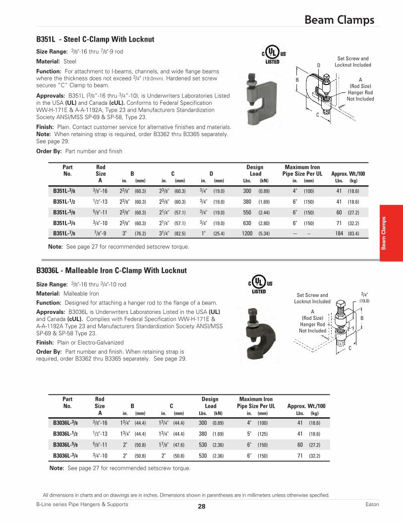
Size Range: 3/8"-16 thru 7/8"-9 rod
Material: Steel
Function: For attachment to I-beams, channels, and wide flange beamswhere the thickness does not exceed 3/4" (19.0mm). Hardened set screwsecures “C” Clamp to beam.
Approvals: B351L (3/8”-16 thru 3/4”-10), is Underwriters Laboratories Listedin the USA (UL) and Canada (cUL). Conforms to Federal Specification WW-H-171E & A-A-1192A, Type 23 and Manufacturers StandardizationSociety ANSI/MSS SP-69 & SP-58, Type 23.
Finish: Plain. Contact customer service for alternative finishes and materials.Note: When retaining strap is required, order B3362 thru B3365 separately.See page 29.
Order By: Part number and finish
Part Rod Design Maximum IronNo. Size B C D Load Pipe Size Per UL Approx. Wt./100
A in. (mm) in. (mm) in. (mm) Lbs. (kN) in. (mm) Lbs. (kg)
B351L-3/8 3/8"-16 23/8" (60.3) 23/8" (60.3) 3/4" (19.0) 300 (0.89) 4" (100) 41 (18.6)
B351L-1/2 1/2"-13 23/8" (60.3) 23/8" (60.3) 3/4" (19.0) 380 (1.69) 6" (150) 41 (18.6)
B351L-5/8 5/8"-11 23/8" (60.3) 21/4" (57.1) 3/4" (19.0) 550 (2.44) 6" (150) 60 (27.2)
B351L-3/4 3/4"-10 23/8" (60.3) 21/4" (57.1) 3/4" (19.0) 630 (2.80) 6" (150) 71 (32.2)
B351L-7/8 7/8"-9 3" (76.2) 31/4" (82.5) 1" (25.4) 1200 (5.34) -- -- 184 (83.4)
B351L - Steel C-Clamp With Locknut
B3036L - Malleable Iron C-Clamp With Locknut
Note: See page 27 for recommended setscrew torque.
Note: See page 27 for recommended setscrew torque.
Size Range: 3/8"-16 thru 3/4"-10 rod
Material: Malleable Iron
Function: Designed for attaching a hanger rod to the flange of a beam.
Approvals: B3036L is Underwriters Laboratories Listed in the USA (UL)and Canada (cUL). Complies with Federal Specification WW-H-171E & A-A-1192A Type 23 and Manufacturers Standardization Society ANSI/MSSSP-69 & SP-58 Type 23.
Finish: Plain or Electro-Galvanized
Order By: Part number and finish. When retaining strap isrequired, order B3362 thru B3365 separately. See page 29.
Set Screw andLocknut Included
Set Screw andLocknut Included
A(Rod Size)Hanger RodNot Included
A(Rod Size)Hanger RodNot Included
B
3/4"(19.0)
C
B
C
D
Beam Clamps
Part Rod Design Maximum IronNo. Size B C Load Pipe Size Per UL Approx. Wt./100
A in. (mm) in. (mm) Lbs. (kN) in. (mm) Lbs. (kg)
B3036L-3/8 3/8"-16 13/4" (44.4) 13/4" (44.4) 300 (0.89) 4" (100) 41 (18.6)
B3036L-1/2 1/2"-13 13/4" (44.4) 13/4" (44.4) 380 (1.69) 5" (125) 41 (18.6)
B3036L-5/8 5/8"-11 2" (50.8) 17/8" (47.6) 530 (2.36) 6" (150) 60 (27.2)
B3036L-3/4 3/4"-10 2" (50.8) 2" (50.8) 530 (2.36) 6" (150) 71 (32.2)
Beam Clamps
28 Eaton
All dimensions in charts and on drawings are in inches. Dimensions shown in parentheses are in millimeters unless otherwise specified.
B-Line series Pipe Hangers & Supports

Size Range: 6” (152.4mm) to 12” (304.8mm)lengths
Material: Steel (Stainless Steel available)
Finish: Pre-Galvanized
Function: Designed for use with B351Land B3036L C-Clamps.
Order By: Part number, length 'L', (add1" (25.4) minimum to flange width), and finish.
Note: Requires field forming on beam.
Material: Malleable Iron
Function: Designed for attaching a 3/8"-16 hanger rod to thebottom flange of a Z-purlin.
Approvals: Underwriters Laboratories Listed in the USA (UL) andCanada (cUL) for up to 4” (100mm) pipe. Conforms to FederalSpecification WW-H-171E & A-A-1192A, Type 23 and ManufacturersStandardization Society ANSI/MSS SP-69 & SP-58, Type 23.
Finish: Plain or Electro-Galvanized
Order By: Part number and finish.
Weight: Approx. Wt./100 90 Lbs. (40.8kg)
Design Load: 400 Lbs. (1.78kN)
B3362, B3363, B3364, B3365 - Retaining Strap
B3037 - Z-Purlin Malleable C-Clamp
Note: See page 27 for recommended setscrew torque.
Material Thickness12 Gauge (2.7)
B 3/4"(19.0)
Approx. Wt./100 for Length 'L' ofPart For Use With A B 6" (152.4) 8" (203.2) 10" (254.0) 12" (304.8)No. in. (mm) in. (mm) Lbs. (kg) Lbs. (kg) Lbs. (kg) Lbs. (kg)
B3362-L B351L-3/8 & 1/2 11/4" (31.7) 7/16" (11.1) 27 (12.2) 35 (15.9) 44 (19.9) 52 (23.6)
B3363-L B351L-5/8 & 3/4, 11/4" (31.7) 5/8" (15.9) 26 (11.8) 35 (15.9) 43 (19.5) 52 (23.6)B3036L-3/8 & 1/2
B3364-L B3036L-5/8 & 3/4 11/4" (31.7) 11/16" (17.4) 26 (11.8) 35 (15.9) 43 (19.5) 52 (23.6)
B3365-L B351L-7/8 11/2" (38.1) 3/4" (19.0) 32 (14.5) 42 (19.0) 52 (23.6) 62 (28.1)
Set Screw andLocknut Included
3"(76.2)
313/32"(86.5)
Throat Opening31/32" (24.6)
Bottom HangerRod Threads
3/8"-16
L
A
Beam
Clam
ps
Flange Width Length Lin. (mm) in. (mm)
3”-5” (76-127) 6” (152.4)
5”-7” (127-178) 8” (203.2)
7”-9” (178-228) 10” (254.0)9”-11” (228-279) 12” (304.8)
All dimensions in charts and on drawings are in inches. Dimensions shown in parentheses are in millimeters unless otherwise specified.
Beam Clamps
29 B-Line series Pipe Hangers & SupportsEaton
Note: See page 27 for recommended setscrew torque.
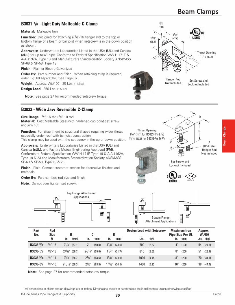
Size Range: 3/8"-16 thru 3/4"-10 rodMaterial: Cast Malleable Steel with hardened cup point set screwand jam nut
Function: For attachment to structural shapes requiring wider throatespecially under roof with bar joist construction.This clamp may be used with the set screw in the up or down position.
Approvals: Underwriters Laboratories Listed in the USA (UL) andCanada (cUL), and Factory Mutual Engineering Approved (FM).Conforms to Federal Specification WW-H-171E Type 19 & A-A-1192A,Type 19 & 23 and Manufacturers Standardization Society ANSI/MSSSP-69 & SP-58, Type 19 & 23.
Finish: Plain. Contact customer service for alternative finishes and materials.
Order By: Part number, rod size and finish
Note: Do not over tighten set screw.
Part Rod Design Load with Setscrew Maximum Iron Approx.No. Size B C D Pipe Size Per UL Wt./100
A in. (mm) in. (mm) in. (mm) Lbs. (kN) in. (mm) Lbs. (kg)
B3033-3/8 3/8"-16 21/4" (57.1) 2" (50.8) 11/8" (28.6) 500 (2.22) 4" (100) 54 (24.5)
B3033-1/2 1/2"-13 25/16" (58.7) 23/16" (55.6) 11/4" (31.7) 810 (3.60) 8" (200) 51 (23.1)
B3033-5/8 5/8"-11 25/8" (66.7) 21/2" (63.5) 13/8" (34.9) 1000 (4.45) 8" (200) 70 (31.7)
B3033-3/4 3/4"-10 211/16" (68.3) 21/2" (63.5) 17/16" (36.5) 1400 (6.23) 10" (250) 98 (44.4)
Set Screw andLocknut Included
A(Rod Size)Hanger RodNot Included
B
DC
Throat Opening11/4" (31.7) for B3033-3/4 & 1/215/16" (33.3) for B3033-5/8 & 3/4
Beam Clamps
Bottom FlangeAttachment Applications
B3033 - Wide Jaw Reversible C-Clamp
Top Flange AttachmentApplications
Material: Malleable Iron
Function: Designed for attaching a 3/8"-16 hanger rod to the top orbottom flange of a beam or bar joist when setscrew is in the down positionas shown.
Approvals: Underwriters Laboratories Listed in the USA (UL) and Canada(cUL) for up to 4” pipe. Conforms to Federal Specification WW-H-171E & A-A-1192A, Type 19 and Manufacturers Standardization Society ANSI/MSSSP-69 & SP-58, Type 19.
Finish: Plain or Electro-Galvanized
Order By: Part number and finish. When retaining strap is required,order Fig. 69 separately. See Page 37.
Weight: Approx. Wt./100 25 Lbs. (11.3kg)
Design Load: 350 Lbs. (1.55kN)
B3031-3/8 - Light Duty Malleable C-Clamp
Note: See page 27 for recommended setscrew torque.
Hanger RodNot Included
Set Screw andLocknut Included
Throat Opening11/16" (17.5)
3/4"(19.0)
11/2"(38.1)
17/8"(47.6)
Beam Clamps
30 Eaton
All dimensions in charts and on drawings are in inches. Dimensions shown in parentheses are in millimeters unless otherwise specified.
B-Line series Pipe Hangers & Supports

B3034 - C-Clamp
Note: See page 27 for recommended setscrew torque.
Size Range: 3/8"-16 thru 3/4"-10 rod
Material: Cast Malleable Steel with hardened cup point setscrew and jam nut
Function: Recommended for hanging from steel beamwhere flange thickness does not exceed 3/4" (19.0mm).
Features: May be used on top or bottom flange of thebeam. Beveled lip allows hanging from top flange where clearance is limited. may be installed with the set screw in the up or down position. Offset design permits unlimited rodadjustment by allowing the rod to be threaded completelythrough the clamp. The rear window design permits inspection of thread engagement.
Approvals: Underwriters Laboratories Listed in the USA(UL) and Canada (cUL), and Factory Mutual EngineeringApproved (FM) for 3/8”-16 and 1/2”-13 rod sizes. Conforms to Federal Specification WW-H-171E & A-A-1192A, Type 19 & 23 and Manufacturers StandardizationSociety ANSI/MSS SP-69 & SP-58, Type 19 & 23. 3/8"-16 is(cULus) Listed to support up to 4" (100mm) pipe with the setscrew in the down position, up to 3" (75mm) pipe with the set screw in the up position. 1/2"-13 is (cULus) Listed to support up to 8" (200mm) pipe with the set screw in the down position, up to 6" (150mm) pipe with the set screw in the up position.
Finish: Plain. Contact customer service for alternative finishesand materials.
Order By: Part number and finish
Set Screw andLocknut Included
A(Rod Size)Hanger RodNot Included
B
DC
ThroatOpening3/4" (19.0)
B3034-5/8" and B3034-3/4" sizesAttach only as shown.
Top FlangeAttachmentApplications
Bottom FlangeAttachmentApplications
Set Screw andLocknut Included
B3034-3/8Shown
A(Rod Size)Hanger RodNot Included
B
DC
ThroatOpening3/4" (19.0)
B3034-3/8" and B3034-1/2" sizesAttach only as shown.
Beam
Clam
ps Part Rod Design Load with Setscrew Maximum Iron Approx.No. Size B C D Pipe Size Per UL Wt./100
A in. (mm) in. (mm) in. (mm) Lbs. (kN) in. (mm) Lbs. (kg)
B3034-3/8 3/8"-16 15/8" (41.3) 2" (50.8) 7/8" (19.0) 560 (2.49) 4" (100) 30 (13.6)
B3034-1/2 1/2"-13 113/16" (46.0) 23/16" (55.6) 13/16" (30.2) 810 (3.60) 8" (200) 47 (21.3)
B3034-5/8 5/8"-11 13/4" (44.5) 21/8" (54.0) 11/4" (31.7) 1000 (4.45) -- -- 58 (26.3)
B3034-3/4 3/4"-10 2" (50.8) 21/4" (57.2) 11/4" (31.7) 1500 (6.67) -- -- 77 (35.0)
Beam Clamps
All dimensions in charts and on drawings are in inches. Dimensions shown in parentheses are in millimeters unless otherwise specified.
31 B-Line series Pipe Hangers & SupportsEaton

Size Range:3/8"-16 rod sizes thru 7/8"-9 rod sizes
Material: Cast Malleable Steel with hardened cup point set screw and jam nut
Function: Recommended for hanging from steel beam where flange thickness doesnot exceed 3/4” (19.0mm) on Fig. 68S or 11/4” (31.7mm) on Fig.68W.
Features: May be used on top or bottom flange of beam. Beveled lip allows hangingfrom top flange where clearance is limited. May be installed with set screw in up ordown position. Offset design permits unlimited rod adjustment by allowing the rod tobe threaded completely through the clamp. The rear window design permits inspectionof thread engagement.
Approvals: Factory Mutual Engineering Approved (FM). Underwriters LaboratoriesListed in the USA (UL) and Canada (cUL), Conforms to Federal SpecificationWW-H-171E, Type 23 and Manufacturers Standardization Society SP-58, Type 19. Fig. 68S-3/8 is (cULus) Listed to support up to 4” (100mm) pipe with the set screw in the down position and up to 3” (80mm) pipe with the set screw in the up position.Fig. 68S-1/2 is (cULus) Listed to support up to 8” (200mm) pipe with the set screw in the down position and up to 6” (150mm) pipe with the set screw in the up position.Fig. 68W-3/8 is (cULus) Listed to support up to 4” (100mm) pipe with the set screw in the down position and up to 4” (100mm) pipe with the set screw in the up position.Fig. 68W-1/2 is (cULus) Listed to support up to 6” (150mm) pipe with the set screw in the down position and up to 6” (150mm) pipe with the set screw in the up position.Factory Mutual Engineering Approved (FM) only with the set screw in the down position.
(OSHPD). For additional load spacing and placement information relating to OSHPDprojects, please refer to the Seismic Restraint System Guidelines.
Finish: Plain. Contact customer servicefor Electro-Galvanized finish.
Order By: Part number and finish
C Max Rec. Load Max Rec. Load Approx.Part Rod Size B Min. D E F Set Screw Up Set Screw Down Wt./100No. A in. (mm) in. (mm) in. (mm) in. (mm) in. (mm) Lbs. (kN) Lbs. (kN) Lbs. (kg)
68W-3/8 3/8”-16 19/16” (39.7) 11/4” (31.7) 11/8” (28.6) 7/16” (11.1) 7/8” (22.2) 610 (2.71) 610 (2.71) 41 (18.6)
68W-1/2 1/2”-13 19/16” (39.7) 11/4” (31.7) 1” (25.4) 5/8” (15.9) 11/8” (28.6) 750 (3.33) 1130 (5.02) 66 (29.9)
68W-5/8 5/8”-11 11/2” (38.1) 11/4” (31.7) 1” (25.4) 9/16” (14.3) 11/8” (28.6) 750 (3.33) 1130 (5.02) 68 (30.8)
68W-3/4 3/4”-10 13/4” (44.4) 11/4” (31.7) 11/8” (28.6) 3/8” (19.5) 11/4” (31.7) 750 (3.33) 1130 (5.02) 110 (49.9)
68W-7/8 7/8”-9 13/4” (44.4) 11/4” (31.7) 11/8” (28.6) 9/16” (14.3) 15/16” (33.3) 750 (3.33) 1130 (5.02) 98 (44.4)
TOLCO™ Fig. 68S - Reversible Malleable Beam Clamp 3/4” (19.0mm) Throat OpeningTOLCO™ Fig. 68W - Reversible Malleable Beam Clamp 11/4” (31.7mm) Throat Opening (bottom of page)
Beam Clamps
Beam Clamps
Fig. 68S
Fig. 68W
Fig. 68W
C Max Rec. Load Max Rec. Load Approx.Part Rod Size B Min. D E F Set Screw Up Set Screw Down Wt./100No. A in. (mm) in. (mm) in. (mm) in. (mm) in. (mm) Lbs. (kN) Lbs. (kN) Lbs. (kg)
68S-3/8 3/8”-16 19/16” (39.7) 3/4” (19.0) 11/8” (28.6) 7/16” (11.1) 7/8” (22.2) 610 (2.71) 610 (2.71) 32 (14.5)
68S-1/2 1/2”-13 15/8” (41.3) 3/4” (19.0) 1” (25.4) 7/16” (11.1) 11/8” (28.6) 750 (3.33) 1130 (5.02) 54 (24.5)
68S-5/8 5/8”-11 19/16” (39.7) 3/4” (19.0) 1” (25.4) 9/16” (14.3) 11/8” (28.6) 750 (3.33) 1130 (5.02) 50 (22.7)
68S-3/4 3/4”-10 13/4” (44.4) 3/4” (19.0) 11/8” (28.6) 9/16” (14.3) 11/4” (31.7) 750 (3.33) 1130 (5.02) 81 (36.7)
68S-7/8 7/8”-9 13/4” (44.4) 3/4” (19.0) 11/8” (28.6) 9/16” (14.3) 15/16” (33.3) 750 (3.33) 1130 (5.02) 75 (34.0)
Fig. 68S
Set Screw andLocknut Included
A(Rod Size)Hanger RodNot Included
B
DF
E
C
Set Screw andLocknut Included
A(Rod Size)Hanger RodNot Included
B
DF
E
C
Fig. 68S
Fig. 68W
D = Depth of Throat
Note: See page 27 for recommended setscrew torque.
32 Eaton
All dimensions in charts and on drawings are in inches. Dimensions shown in parentheses are in millimeters unless otherwise specified.
B-Line series Pipe Hangers & Supports

Beam
Clam
ps
Beam Clamps
Size Range:Fig. 65 - 1/2"-13 rod sizes, and 5/8"-11 rod sizesFig. 65XT - 3/8"-16 rod size (see below)
Material: Steel with hardened cup point set screw and jam nut
Function: Recommended for hanging from steel beam where flange thickness doesnot exceed 3/4” (19.0mm).
Features: All steel construction eliminates structural deficiencies associated withcasting type beam clamps. May be used on top or bottom flange of beam. (Beveled lipallows hanging from top flange where clearance is limited.) May be installed with setscrew in up or down position. Offset design permits unlimited rod adjustment byallowing the rod to be threaded completely through the clamp. Open design permitsinspection of thread engagement.
Approvals: Underwriters Laboratories Listed in the USA (UL) and Canada (cUL).Exceeds requirements of the National Fire Protection Association (NFPA), pamphlet 13,3/8"-16 rod will support 1/2” (15mm) thru 4” (100mm) pipe1/2"-13 rod will support 1/2” (15mm) thru 8” (200mm) pipeIncluded in the Seismic Restraints Catalog approved by the State of CaliforniaOffice of Statewide Health Planning and Development (OSHPD). For additionalload spacing and placement information relating OSHPD projects, please refer tothe Seismic Restraint System Guidelines.
Finish: Plain. Contact customer service for alternative finishes and materials.
Order By: Part number and finish
Fig. 65 Patent #4,570,885
Part Rod Size B C D ENo. A in. (mm) in. (mm) in. (mm) in. (mm)
65-1/2 1/2”-13 11/2” (38.1) 3/4” (19.0) 1” (25.4) 9/16” (14.3)
65-5/8 5/8”-11 11/2” (38.1) 3/4” (19.0) 1” (25.4) 9/16” (14.3)
Part F Mac Rec. Load * Approx. Wt./100No. in. (mm) lbs. (kN) lbs. (kg)
65-1/2 11/4” (31.7) 1130 (5.02) 55 (24.9)
65-5/8 11/4” (31.7) 1130 (5.02) 55 (24.9)
TOLCO™ Fig. 65 - Reversible Steel C-Type Beam Clamp 3/4” (19.0mm) Throat OpeningTOLCO™ Fig. 65XT - Reversible Steel C-Type Beam Clamp 3/4” (19.0mm) Throat Opening (bottom of page)
Fig. 65XT-3/8 - Beam Clamp
B
F
E
A
C
D
Component of State ofCalifornia OSHPD ApprovedSeismic Restraints System
* Maximum loads for clamp with set screw in up or down position.
Feature: Extruded holes allow for more threadengagement of threaded rod and set screw.
Weight: Approx. Wt./100 - 28.0 Lbs. (12.7kg)
Design Load: 730 Lbs (3.25kN)
Finish: Plain or Electro-Galvanized
Order By: Part number and finishApprovals: Underwriters Laboratories Listed inthe USA (UL) and Canada (cUL), and FactoryMutual Engineering Approved (FM) for up to 4” (100mm) pipe.
3/4"(19.0)
19/16"(39.7)
11/8"(28.6)
7/8"(22.2)13/8"
(34.9)
Set Screw andLocknut Included
Set Screw andLocknut Included
Note: See page 27 for recommended setscrew torque.
Note: See page 27 for recommended setscrew torque.
All dimensions in charts and on drawings are in inches. Dimensions shown in parentheses are in millimeters unless otherwise specified.
33 B-Line series Pipe Hangers & SupportsEaton

Beam Clamps
Beam Clamps
Size Range: 3/8"-16, 1/2"-13 rod sizes, and 5/8"-11 rod sizes
Material: Steel with hardened cup point set screw and jam nut
Function: Recommended for hanging from steel beam where flangethickness does not exceed 11/4” (31.7mm).
Features: All steel construction eliminates structural deficiencies associated with casting type beam clamps. May be used on top or bottom flange of beam. (Beveled lipallows hanging from top flange where clearance is limited.) May be installed with setscrew in up or down position. Offset design permits unlimited rod adjustment byallowing the rod to be threaded completely through the clamp. Open design permitsinspection of thread engagement.
Approvals: Underwriters Laboratories Listed in the USA (UL) and Canada (cUL).Exceeds requirements of the National Fire Protection Association (NFPA), pamphlet 13,3/8"-16 rod will support 1/2” (15mm) thru 4” (100mm) pipe1/2"-13 rod will support 1/2” (15mm) thru 8” (200mm) pipeIncluded in the Seismic Restraints Catalog approved by the State of CaliforniaOffice of Statewide Health Planning and Development (OSHPD). For additional loadspacing and placement information relating OSHPD projects, please refer to theSeismic Restraint System Guidelines.
Finish: Plain. Contact customer service for alternative finishes and materials.
Order By: Part number and finish
Part Rod Size B C D ENo. A in. (mm) in. (mm) in. (mm) in. (mm)
66-3/8 3/8”-16 13/16" (30.2) 11/4” (31.7) 1” (25.4) 7/16” (11.1)
66-1/2 1/2”-13 11/2” (38.1) 11/4” (31.7) 1” (25.4) 9/16” (14.3)
66-5/8 5/8”-11 11/2” (38.1) 11/4” (31.7) 1” (25.4) 9/16” (14.3)
Part F Mac Rec. Load * Approx. Wt./100No. in. (mm) lbs. (kN) lbs. (kg)
66-3/8 1” (25.4) 610 (2.71) 28 (12.7)
66-1/2 11/4” (31.7) 1130 (5.02) 55 (24.9)
66-5/8 11/4” (31.7) 1130 (5.02) 55 (24.9)
TOLCO™ Fig. 66 - Reversible Steel C-Type Beam Clamp 11/4” (31.7mm) Throat Opening
B
E
A
C
D
F
Component of State ofCalifornia OSHPD ApprovedSeismic Restraints System
* Maximum loads for clamp with set screw in up or down position.
Set Screw andLocknut Included
Note: See page 27 for recommended setscrew torque.
34 Eaton
All dimensions in charts and on drawings are in inches. Dimensions shown in parentheses are in millimeters unless otherwise specified.
B-Line series Pipe Hangers & Supports

Beam
Clam
ps
Beam Clamps
Size Range: 3/8"-16 and 1/2"-13 rod sizes
Material: Stainless Steel (Type 316 or 304)
Function: Recommended for hanging from steel beams where flange thickness doesnot exceed 3/4” (19.0mm) for Fig. 67SS or 11/4” (31.7mm) for Fig. 68SS.
Features: All steel construction eliminates structural deficiencies associated withcasting type beam clamps. May be used on top or bottom flange of beam. May beinstalled with set screw in up or down position. Offset design permits unlimited rodadjustment by allowing the rod to be threaded completely through the clamp.
Approvals: Underwriters Laboratories Listed in the USA (UL) and Canada (cUL).Conforms to Manufacturers Standardization Society ANSI/MSS SP-69 & SP-58,Type 19. Meets or exceeds requirements of the National Fire Protection Association(NFPA), pamphlet 13.3/8"-16 rod will support 1/2” (15mm) thru 4” (100mm) pipe1/2"-13 rod will support 1/2” (15mm) thru 8” (200mm) pipe
Order By: Part number and stainless steel type.
Part Rod Size Pipe Size B C D ENo. A in. (mm) in. (mm) in. (mm) in. (mm) in. (mm)
67SS-3/8 3/8”-16 1/2" - 4” (15 - 100) 3” (76,2) 7/8” (22.2) 1” (25.4) 15/8” (41.3)
67SS-1/2 1/2”-13 5" - 8” (125 -200) 3” (76,2) 7/8” (22.2) 1” (25.4) 15/8” (41.3)
Part F G Test Load Approx. Wt./100No. in. (mm) in. (mm) lbs. (kN) lbs. (kg)
67SS-3/8 15/8” (41.3) 11/8” (28.6) 1500 (6.67) 84 (38.1)
67SS-1/2 15/8” (41.3) 11/8” (28.6) 4050 (18.01) 170 (77.1)
Part Rod Size Pipe Size B C D ENo. A in. (mm) in. (mm) in. (mm) in. (mm) in. (mm)
68SS-3/8 3/8”-16 1/2" - 4” (15 - 100) 21/16” (52.4) 11/8” (28.6) 3/4” (19.0) 11/4” (31.7)
68SS-1/2 1/2”-13 5" - 8” (125 -200) 21/4” (57.1) 11/4” (31.7) 13/16” (20.6) 11/4” (31.7)
Part F Test Load Approx. Wt./100No. in. (mm) lbs. (kN) lbs. (kg)
68SS-3/8 2” (50.8) 1500 (6.67) 84 (38.1)
68SS-1/2 21/4” (57.1) 4050 (18.01) 170 (77.1)
TOLCO™ Fig. 67SS - Stainless Steel Reversible C-Type Beam Clamp 3/4” (19.0mm) Throat OpeningTOLCO™ Fig. 68SS - Stainless Steel Reversible C-Type Beam Clamp Wide Mouth
Fig. 67SS
Fig. 68SS *
B
G
E
A
C
D
F
Set Screw andLocknut Included
* Fig. 68SS minimum order quantity of 30 pieces.Note: See page 27 for recommended setscrew torque.
All dimensions in charts and on drawings are in inches. Dimensions shown in parentheses are in millimeters unless otherwise specified.
35 B-Line series Pipe Hangers & SupportsEaton

Beam Clamps
Beam Clamps
Size Range: 3/8"-16 thru 3/4"-10 rodMaterial: SteelFunction: Designed for attaching a hanger rod to the flange of a beam.Approvals: Conforms to Federal Specification WW-H-171E &A-A-1192A, Type 19 and Manufacturers Standardization SocietyANSI/MSS SP-69 & SP-58, Type 19.Finish: Electro-Galvanized or Hot-Dip GalvanizedOrdering: Part number and finish. When retaining strap is required,order B312 separately. See page 39.
Recommended Set Screw Torque: 1/2”-13 = 350 in-lbs (39.5 N•m)5/8”-11 = 700 in-lbs (79.0 N•m)
Minimum Flange Thickness: For B321-1 thru B321-3 = 3/8” (9.5) For B321-4 & B321-5 = 5/8” (15.9)
Size Range: 1/4"-20 thru 5/8"-11 rod
Material: Steel
Function: Designed for attaching a hanger rod to the flange of a beam.
Approvals: Conforms to Federal Specification WW-H-171E & A-A-1192A,Type 19 and Manufacturers Standardization Society ANSI/MSS SP-69 &SP-58, Type 19.
Finish: Electro-Galvanized or Hot-Dip Galvanized
Order By: Part number and finish. When retaining strap is required, orderB312 separately. See page 39.
Recommended Set Screw Torque: 3/8”-16 = 150 in-lbs (16.9 N•m)1/2”-13 = 350 in-lbs (39.5 N•m)
Part Rod Size Setscrew C T Design Load Approx. Wt./100No. A Size in. (mm) in. (mm) Lbs. (kN) Lbs. (kg)
B303 1/4”-20 3/8”-16 25/16" (58.7) 11 Ga. (3.0) 400 (1.78) 72 (32.6)
B304 5/16”-18 3/8”-16 25/16" (58.7) 11 Ga. (3.0) 600 (2.67) 72 (32.6)
B305 3/8”-16 3/8”-16 25/16" (58.7) 11 Ga. (3.0) 600 (2.67) 72 (32.6)
B306 3/8”-16 1/2”-13 27/16" (61.9) 7 Ga. (4.5) 1100 (4.89) 97 (44.0)
B307 1/2”-13 1/2”-13 27/16" (61.9) 7 Ga. (4.5) 1100 (4.89) 97 (44.0)
B308 1/2”-13 1/2”-13 29/16" (65.1) 1/4" (6.3) 1500 (6.67) 133 (60.3)
B309 5/8”-11 1/2”-13 29/16" (65.1) 1/4" (6.3) 1500 (6.67) 133 (60.3)
B303-B309 - Beam Clamps
Fig. B321 - Series Beam Clamps
Part Rod Size Setscrew C T Design Load Approx. Wt./100No. A Size in. (mm) in. (mm) Lbs. (kN) Lbs. (kg)
B321-1 3/8”-16 1/2”-13 39/16" (92.1) 1/4" (6.3) 1300 (5.78) 187 (84.8)
B321-2 1/2”-13 1/2”-13 39/16" (92.1) 1/4" (6.3) 1400 (6.23) 186 (84.3)
B321-3 5/8”-11 1/2”-13 39/16" (92.1) 1/4" (6.3) 1600 (7.12) 185 (83.9)
B321-4 5/8”-11 5/8”-11 323/32" (94.4) 5/16" (7.9) 1800 (8.00) 239 (108.4)
B321-5 3/4”-10 5/8”-11 323/32" (94.4) 5/16" (7.9) 2000 (8.89) 238 (107.9)
Set Screw Included
C
T
A
111/16" (42.8)MaximumFlange
Thickness
15/8"(41.3)
31/4"(82.5)
C
T
A
7/8" (22.2)MaximumFlange
Thickness
11/8"(28.6)
21/2"(63.5)
Set Screw Included
36 Eaton
All dimensions in charts and on drawings are in inches. Dimensions shown in parentheses are in millimeters unless otherwise specified.
B-Line series Pipe Hangers & Supports

Beam
Clam
ps
Beam Clamps
Size Range: 3/8"-16 thru 3/4"-10 rod 4” (101,6mm) thru 16” (406.4mm) lengthsNote: longer lengths are available consult factory
Material: Pre-Galvanized Steel
Function: To offer more secure fastening of various types ofbeam clamps to beam where danger of movement might beexpected. NFPA 13 requires the use of retaining straps withall beam clamps installed in earthquake areas. Satisfiesrequirements of NFPA 13.
Important Note: Good installation practice of a retainingstrap requires that the strap be held tightly and securely to allcomponent parts of the assembly. Therefore a lockingmechanism of some kind, such as a hex nut or the beveledlocking slot of the Fig. 69R will provide a more secure reliableinstallation.
Approvals: Underwriters Laboratories Listed in the USA (UL)and Canada (cUL). Approved for use with any listed beamclamp. Included in the Seismic Restraints Catalog approvedby the State of California Office of Statewide Health Planningand Development (OSHPD). For additional load spacing andplacement information relating OSHPD projects, please referto the Seismic Restraint System Guidelines.
Finish: Pre-Galvanized
Order By: Part number, length (L), and finish.
Notes: Minimum return on strap is 1” (25.4mm)Lengths over 16” (406mm) are not UL Listed
TOLCO™ Fig. 69 - Beam Clamp Retaining Strap
Hole Dia. D For Use With LengthPart No. in. (mm)
69-3/8-1/2-LB3033-3/8, B3034-3/8, B3031-3/8,
Specifysee drawing 65-3/8, 65XT-3/8, 66-3/8B3033-1/2, B3034-1/2, 65-1/2, 66-1/2
69-5/8-L 11/16” (17.5) B3033-5/8, 65-5/8, 66-5/8 Specify
69-3/4-L 13/16” (20.6) B3033-3/4 Specify
Component of State ofCalifornia OSHPD ApprovedSeismic Restraints System
All dimensions in charts and on drawings are in inches. Dimensions shown in parentheses are in millimeters unless otherwise specified.
37 B-Line series Pipe Hangers & SupportsEaton
Fig. 69-5/8 & 3/4
Fig. 69-3/8-1/2
D
7/16"(11.1)
9/16"(14.3)

Beam Clamps
Beam Clamps
Size Range: 3/8"-16 & 1/2"-13 rod 4” (101,6mm) thru 16” (406.4mm) lengthsNote: longer lengths are available consult factory
Material: Pre-Galvanized Steel
Function: To offer more secure fastening of various types ofbeam clamps to beam where danger of movement might beexpected. NFPA 13 requires the use of retaining straps withall beam clamps installed in earthquake areas. Satisfiesrequirements of NFPA 13.
Features: Beveled locking slot* is precisely formed to alignwith the threaded section of a hanger rod or set screw andengage the unit securely. May be used as shown in Section“A-A” or inverted. Allows easy installation for new constructionor retrofit applications.
Important Note: Good installation practice of a retainingstrap requires that the strap be held tightly and securely to allcomponent parts of the assembly. Therefore a lockingmechanism of some kind, such as a hex nut or the beveledlocking slot of the Fig. 69R will provide a more secure reliableinstallation.
Approvals: Underwriters Laboratories Listed in the USA (UL)and Canada (cUL). Approved for use with any listed beamclamp. Included in the Seismic Restraints Catalog approvedby the State of California Office of Statewide Health Planningand Development (OSHPD). For additional load spacing andplacement information relating OSHPD projects, please referto the Seismic Restraint System Guidelines.
Finish: Pre-Galvanized
Order By: Part number, length, and finish.
Note: Minimum return on strap is 1” (25.4mm)
* Patent #5,947,424
TOLCO™ Fig. 69R - Retrofit Capable Beam Clamp Retaining Strap
Slot Width For Use With LengthPart No. in. (mm)
69R-3/8-L 7/16” (11.1)B3033-3/8, B3034-3/8, B3031-3/8, Specify
65-3/8, 65XT-3/8, 66-3/8
69R-1/2-L 9/16” (14.3) B3033-1/2, B3034-1/2, 65-1/2, 66-1/2 Specify
Component of State ofCalifornia OSHPD ApprovedSeismic Restraints System
A
A
A - A
38 Eaton
All dimensions in charts and on drawings are in inches. Dimensions shown in parentheses are in millimeters unless otherwise specified.
B-Line series Pipe Hangers & Supports

Beam
Clam
ps
Beam Clamps
Size Range: 9” (228.6mm) to 18” (457.2mm) strap lengths
Material: Steel
Function: Designed for use with B303-B309 and B321 beam clamps.
Finish: Pre-Galvanized
Order By: Part number and finish.
Notes:Maximum beam thickness 3/4” (19.0). For thicker beams step up one flange width size.Requires field forming on beam.
Part For Flange With L Approx. Wt./100No. in. (mm) in. (mm) Lbs. kg
B312-6 6" (152.4) 9" (228.6) 22 (10.0)
B312-9 9" (228.6) 12" (304.8) 30 (13.6)
B312-12 12" (304.8) 15" (381.0) 40 (18.1)
B312-15 15" (381.0) 18" (457.2) 49 (22.2)
B312 - Retaining Strap Material Thickness14 Gauge (1.9)
L
1/4"(6.3)
1/2"(12.7)
11/4"(31.7)
13/4"(44.4)
All dimensions in charts and on drawings are in inches. Dimensions shown in parentheses are in millimeters unless otherwise specified.
39 B-Line series Pipe Hangers & SupportsEaton
Size Range: 3/8"-16 thru 3/4"-10 rod
Material: Steel
Function: Fits structural I-Beams and wide flange beams, flangewidths 31/2" (88.9mm) to 8" (203.2mm), thickness up to 1/2" (12.7mm).
Approvals: Conforms to Federal Specification WW-H-171E &A-A-1192A, Type 54, and Manufacturers Standardization SocietyANSI/MSS SP-69 & SP-58, Type 27.
Finish: Plain. Contact customer service for alternative finishesand materials.
Order By: Part number and finish
B3040 - Adjustable Beam Clamp
Part Rod Size B C Steel Size Design Load Approx. Wt./100No. A in. (mm) in. (mm) in. (mm) Lbs. (kN) Lbs. (kg)
B3040-3/8 3/8"-16 23/4" (69.8) 113/16" (46.0) 1/4" x 11/4" (6.3 x 31.7) 300 (1.33) 120 (54.4)
B3040-1/2 1/2"-13 23/4" (69.8) 13/4" (44.4) 1/4" x 11/2" (6.3 x 38.1) 700 (3.11) 160 (72.6)
B3040-5/8 5/8"-11 3" (76.2) 13/4" (44.4) 1/4" x 13/4" (6.3 x 44.4) 1000 (4.45) 216 (98.0)
B3040-3/4 3/4"-10 33/8" (85.7) 17/8" (47.6) 3/8" x 2" (9.5 x 50.8) 1800 (8.00) 442 (200.5)
J-Hook and HexNut Included
A(Rod Size)Hanger RodNot Included
CCenter of J-Hook tobottom of clamp body.
B
Steel SizeC

Beam Clamps
Beam Clamps
Material: Steel
Function: Recommended for the suspending of hanger rod fromthe center of an I-beam, equally distributing the load on both sidesof the beam. Use with B3210 eye rod, B3211 welded eye rodor B3200 weldless rye nut.
Approvals: Conforms to Federal Specification WW-H-171E & A-A-1192A,Type 21 and Manufacturers Standardization Society ANSI/MSS SP-69 &SP-58, Type 21.
Finish: Plain. Contact customer service for alternative finishes andmaterials.
Order By: Part number, type, width of flange and finish.
B3050 - Beam Clamp
Bolt and Nut Included
B
'W'C
A
Steel Size
Bolt Size
ACenter of bolt to bottom of
beam flange.
Part Flange ThicknessNumber Bolt Min. Max. A B C Steel Size Design Load& Size Size in. (mm) in. (mm) in. (mm) in. (mm) in. (mm) in. (mm) Lbs. (kN)
B3050-2 X * 1/2"-13 3/16" (4.8) 1/2" (12.7) 13/8" (34.9) 5/8" (15.9) 21/8" (54.0) 1/4"x 11/4" (6.3 x 31.7) 1000 (3.11)
B3050-5 X * 3/4"-10 5/8" (25.9) 1" (25.4) 17/8" (47.6) 7/8" (22.2) 3" (76.2) 1/2"x 2" (12.7 x 50.8) 3000 (6.67)
Flange Width Approx. Wt./100 For Beam Clamp Size
* 'W' 2 5in. (mm) lbs. (kg) lbs. (kg)
4 4" (101.6) 116 (52.6) 429 (194.6)
5 5" (127.0) 125 (56.7) 458 (207.8)
6 6" (152.4) 134 (60.8) 486 (220.5)
7 7" (177.8) 143 (64.9) 514 (233.2)
8 8" (203.2) 152 (69.0) 543 (246.3)
9 9" (228.6) 160 (72.6) 571 (259.0)
10 10" (254.0) 169 (76.7) 599 (271.8)
12 12" (304.8) 187 (84.8) 656 (297.6)
40 Eaton
All dimensions in charts and on drawings are in inches. Dimensions shown in parentheses are in millimeters unless otherwise specified.
B-Line series Pipe Hangers & Supports
* Any flange width shown in bottom chart.

Beam
Clam
ps
Beam Clamps
Size Range: 3/8"-16 thru 1"-8 rod
Material: Steel
Function: Designed for attaching a hanger rod to be centered under beam flanges.2" (50.8mm) vertical adjustment is provided in the clamp.
Approvals: Conforms to Federal Specification WW-H-171E & A-A-1192A, Type 21and Manufacturers Standardization Society ANSI/MSS SP-69 & SP-58, Type 21.
Finish: Plain or Electro-Galvanized
Order By: Part number, flange width, and finish.
Note: Consult factory for additional flange widths.
B3055 - Steel Beam Clamp
Note:Box Style
Furnished ForB3055-3/8 x 4"B3055-1/2 x 4"B3055-5/8 x 4"B3055-3/4 x 4"B3055-7/8 x 4"B3055-7/8 x 5"B3055-1 x 4"B3055-1 x 5"B3055-1 x 6"
Bolt and NutIncluded
Steel Size
Steel Size
BCenter of cross bolt tobottom of side ofhanger rod nut.
NOTE:Slots on bottom
portions of clamp halvesallow 1” (25.4) adjustment for variance in flange widthsA
(Rod Size)Hanger RodNot Included
A(Rod Size)Hanger RodNot Included
B
B
W
W C
C
Rod Size B C Steel Size Design LoadPart No. A in. (mm) in. (mm) in. (mm) Lbs. (kN)
B3055-3/8 3/8"-16 3" (76.2) 4" (101.6) 1/4" x 11/4" (6.3 x 31.7) 550 (2.44)
B3055-1/2 1/2"-13 3" (76.2) 4" (101.6) 1/4" x 11/2" (6.3 x 38.1) 850 (3.78)
B3055-5/8 5/8"-11 31/4" (82.5) 41/2" (114.3) 3/8" x 11/2" (9.5 x 38.1) 1100 (4.89)
B3055-3/4 3/4"-10 31/4" (82.5) 41/2" (114.3) 3/8" x 2" (9.5 x 50.8) 1500 (6.67)
B3055-7/8 7/8"-9 31/2" (88.9) 5" (127.0) 1/2" x 2" (12.7 x 50.8) 2600 (11.56)
B3055-1 1"-8 31/2" (88.9) 51/2" (139.7) 1/2" x 2" (12.7 x 50.8) 4300 (19.12)
Flange Width W Approximate Wt./100 For Beam Clamp Size Lbs. (kg)
in. (mm) B3055-3/8" B3055-1/2" B3055-5/8" B3055-3/4" B3055-7/8" B3055-1"
4" (101.6) 168 (76.2) 201 (91.2) 328 (148.8) 434 (196.8) 657 (298.0) 797 (361.5)
5" (127.0) 181 (82.1) 217 (98.4) 352 (159.6) 466 (211.4) 667 (302.5) 824 (373.7)
6" (152.4) 193 (87.5) 231 (104.8) 373 (169.2) 495 (224.5) 705 (319.8) 877 (397.8)
7" (177.8) 205 (93.0) 246 (111.6) 395 (179.2) 525 (238.1) 744 (337.5) 926 (420.0)
8" (203.2) 214 (97.1) 256 (116.1) 411 (186.4) 546 (247.6) 773 (350.6) 962 (436.3)
10" (254.0) 235 (106.6) 282 (127.9) 449 (203.6) 596 (270.3) 840 (381.0) 1046 (474.4)
12" (304.8) 259 (117.5) 311 (141.0) 493 (223.6) 655 (297.1) 918 (416.4) 1143 (518.4)
All dimensions in charts and on drawings are in inches. Dimensions shown in parentheses are in millimeters unless otherwise specified.
41 B-Line series Pipe Hangers & SupportsEaton

Beam Clamps
Beam Clamps
Size Range: 3/8"-16 thru 7/8"-9 rod
Material: Malleable Iron
Function: Designed for attaching a hanger rod to the bottomflange of a beam. Adjustable for flange widths of 3" (76.2mm) to7" (177.8mm) and a flange thickness of no greater than 5/8" (15.9mm).
Approvals: Underwriters Laboratories Listed. Conforms toFederal Specification WW-H-171E & A-A-1192A, Type 30 andManufacturers Standardization Society ANSI/MSS SP-69 &SP-58, Type 30.
Finish: Plain or Electro-Galvanized
Ordering: Part number and finish
B3054 - Malleable Iron Beam Clamp With ExtensionB3054WO - Malleable Iron Beam Clamp Without Extension
ERod Take-Out
Clamping Rod andNuts Included
A(Rod Size)Hanger RodNot Included
E
Design Load Max. Iron Pipe Size Per UL Approx. Wt./100Part No. Lbs. (kN) in. (mm) Lbs. (kg)
B3054-3/8 730 (3.25) 4” (100) 236 (107.0)
B3054-1/2 1350 (6.00) 8” (200) 254 (115.2)
B3054-5/8 1365 (6.07) 10” (250) 260 (117.9)
B3054-3/4 1365 (6.07) 10” (250) 278 (126.1)
B3054-7/8 1365 (6.07) 10” (250) 292 (132.4)
RodSize Rod Take Out 'E' For Beam Flange Width Of in. (mm)
Part No. A 3" (76.2) 4" (101.6) 5" (127.0) 6" (152.4) 7" (177.8)
B3054-3/8 3/8"-16 411/16" (119.1) 49/16" (115.9) 45/8" (117.5) 4" (101.6) 31/8" (79.4)
B3054-1/2 1/2"-13 413/16" (122.2) 41/2" (114.3) 45/16" (109.5) 315/16" (100.0) 31/4" (82.5)
B3054-5/8 5/8"-11 47/8" (123.8) 45/8" (117.5) 43/8" (111.1) 33/4" (95.2) 35/16" (84.1)
B3054-3/4 3/4"-10 51/8" (130.2) 5" (127.0) 45/8" (117.5) 41/4" (107.9) 33/4" (95.2)
B3054-7/8 7/8"-9 53/16" (131.8) 47/8" (123.8) 411/16" (119.1) 45/16" (109.5) 33/4" (95.2)
B3054-Rod SizeB3054WO
42 Eaton
All dimensions in charts and on drawings are in inches. Dimensions shown in parentheses are in millimeters unless otherwise specified.
B-Line series Pipe Hangers & Supports

Beam
Clam
ps
Beam Clamps
To determine (mm) in the above chart, multiply inches by 25.4.* Rod Size required to finish part number (see Rod Size 'A' in top chart).∆ These part numbers are furnished with links.
C
E
B
A
B3291, B3292, B3293, B3294, B3295, B3296, B3297, B3298 UFS Beam Clamp With Weldless Eye NutAvailable with left hand threads by adding an L to part number Example: B3291L-*
MaximumBeam Flange Rod Size A
Part No. Thickness (Specify) B C Design Load Approx. Wt./100*Rod Size In. (mm) * In. (mm) In. (mm) Lbs. (kN) Lbs. (kg)
B3291-* .60 (15.2)3/8"-16, 1/2"-13, 11/4" (31.7) 11/8" (28.6) 3230 (14.36) 390 (176.9)5/8"-11, 3/4"-10
B3292-* .60 (15.2) 7/8"-9, 1"-8 111/16" (42.9) 11/8" (28.6) 5900 (26.24) 915 (415.0)
B3293-*∆ .60 (15.2) 3/8"-16, 1/2"-13, 5/8"-11, 111/16" (42.9) 11/8" (28.6) 5900 (26.24) 1300 (589.6)3/4"-10, 7/8"-9, 1"-8
B3294-* 1.031 (26.2) 7/8"-9, 1"-8 11/2" (38.1) 11/8" (28.6) 5900 (26.24) 2165 (982.0)
B3295-*∆ 1.031 (26.2) 7/8"-9, 1"-8 11/2" (38.1) 11/8" (28.6) 5900 (26.24) 3385 (1535.4)
B3296-* 1.031 (26.2) 1"-8, 11/8"-7, 21/8" (54.0) 11/8" (28.6) 11500 (51.15) 2390 (1084.1)11/4"-7, 11/2"-6
B3297-*∆ 1.031 (26.2) 11/8"-7, 11/4"-7, 11/2"-6 21/8" (54.0) 11/8" (28.6) 11500 (51.15) 3575 (1621.6)
B3298-* 1.031 (26.2) 13/4"-5, 2"-41/2 49/16" (115.9) 11/8" (28.6) 11500 (51.15) 3675 (1666.9)
'E' Rod Take-Out For Flange Width
Part No. 3" 4" 5" 6" 7" 8" 9" 10" 11" 12" 13" 14" 15"
B3291-* 41/2" 55/16" 41/16" 35/8" 27/8" -- -- -- -- -- -- -- --
B3292-* -- 43/4" 47/16" 41/16" 33/8" -- -- -- -- -- -- -- --
B3293-*∆ -- -- -- -- 515/16" 6" 55/16" 5" -- -- -- -- --
B3294-* -- 613/16" 65/8" 63/8" 57/8" 57/8" 53/8" 413/16" -- -- -- -- --
B3295-* ∆ -- -- -- -- -- -- -- -- 81/8" 73/4" 71/8" 65/8" 61/16"
B3296-* -- 73/16" 7" 63/4" 61/4" 65/16" 513/16" 53/16" -- -- -- -- --
B3297-* ∆ -- -- -- -- -- -- -- -- 81/2" 81/8" 71/2" 7" 67/16"
B3298-* -- 83/8" 87/16" 83/16" 73/4" 73/4" 71/4" 65/8" -- -- -- -- --
WithLinks
C
E
B
A
Size Range: 3/8"-16 thru 2"-41/2 rod
Material: Forged Steel
Function: Designed for attaching a hanger rod to thebottom flange of a beam. Adjustable from flange widthsof 3" (76.2mm) to 15" (381.0mm). and flange thickness ofno greater than 11/32" (26.2mm).
Approvals: Complies with Federal SpecificationWW-H-171E & A-A-1192A (Type 28 without links;Type 29 with links,) and ANSI/MSS SP-58 (Type 28without links; Type 29 with links).
Finish: Plain or Electro-Galvanized
Order By: Part number, rod size and finish.
Note: Design load for B3291 thru B3295 based onmaximum rod size shown. Use the appropriate allthreaded rod design load shown on page 313 for sizesless than maximum.
WithoutLinks
All dimensions in charts and on drawings are in inches. Dimensions shown in parentheses are in millimeters unless otherwise specified.
43 B-Line series Pipe Hangers & SupportsEaton
B3293B3294
Beam Clamps
Beam Clamps
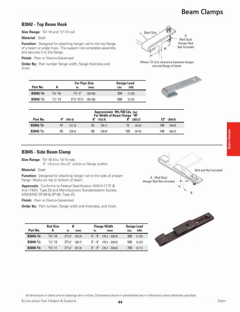
Size Range: 3/8"-16 and 1/2"-13 rod
Material: Steel
Function: Designed for attaching hanger rod to the top flangeof a beam or angle truss. The support rod completes assemblyand secures it to the flange.
Finish: Plain or Electro-Galvanized
Order By: Part number flange width, flange thickness andfinish.
B3042 - Top Beam Hook
B3045 - Side Beam Clamp
Size Range: 3/8"-16 thru 7/8"-9 rods3” (76.2mm) thru 9” (228.6mm) flange widths
Material: Steel
Function: Designed for attaching hanger rod to the side of a beamflange. Works on top or bottom of beam.
Approvals: Conforms to Federal Specification WW-H-171E &A-A-1192A, Type 53 and Manufacturers Standardization SocietyANSI/MSS SP-69 & SP-58, Type 25.
Finish: Plain or Electro-Galvanized
Order By: Part number, flange width and thickness, and finish.
A(Rod Size)Hanger RodNot Included
A (Rod Size)Hanger Rod Not Included
Allows 1/8" (3.2) clearance between hangerrod and flange of beam.
Steel Size
Bolt and Nut Included
B
W
For Pipe Size Design LoadPart No. A in. (mm) Lbs. (kN)
B3042-3/8 3/8"-16 3/4"-2" (20-50) 300 (1.33)
B3042-1/2 1/2"-13 21/2"-31/2" (65-90) 500 (2.22)
Approximate Wt./100 Lbs. (kg)For Width of Beam Flange 'W'
Part No. 4" (101.6) 6" (152.4) 8" (203.2) 12" (304.8)
B3042-3/8 47 (21.3) 62 (28.1) 72 (32.6) 108 (49.0)
B3042-1/2 65 (29.5) 86 (39.0) 105 (47.6) 146 (66.2)
Rod Size B Flange Width Design LoadPart No. A in. (mm) in. (mm) Lbs. (kN)
B3045-3/8 3/8"-16 21/16" (52.4) 3" - 9" (76.2 - 228.6) 300 (1.33)
B3045-1/2 1/2"-13 25/16" (58.7) 3" - 9" (76.2 - 228.6) 500 (2.22)
B3045-5/8 5/8"-11 27/16" (61.9) 3" - 9" (76.2 - 228.6) 700 (3.11)
44 Eaton
All dimensions in charts and on drawings are in inches. Dimensions shown in parentheses are in millimeters unless otherwise specified.
B-Line series Pipe Hangers & Supports
Beam
Clam
ps
Beam Clamps
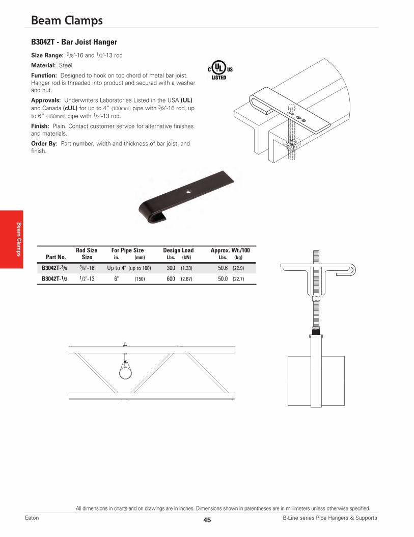
Size Range: 3/8"-16 and 1/2"-13 rod
Material: Steel
Function: Designed to hook on top chord of metal bar joist.Hanger rod is threaded into product and secured with a washerand nut.
Approvals: Underwriters Laboratories Listed in the USA (UL)and Canada (cUL) for up to 4” (100mm) pipe with 3/8"-16 rod, upto 6” (150mm) pipe with 1/2"-13 rod.
Finish: Plain. Contact customer service for alternative finishesand materials.
Order By: Part number, width and thickness of bar joist, andfinish.
B3042T - Bar Joist Hanger
Rod Size For Pipe Size Design Load Approx. Wt./100Part No. Size in. (mm) Lbs. (kN) Lbs. (kg)
B3042T-3/8 3/8"-16 Up to 4" (up to 100) 300 (1.33) 50.6 (22.9)
B3042T-1/2 1/2"-13 6" (150) 600 (2.67) 50.0 (22.7)
All dimensions in charts and on drawings are in inches. Dimensions shown in parentheses are in millimeters unless otherwise specified.
45 B-Line series Pipe Hangers & SupportsEaton

Beam Clamps
Beam Clamps
Size Range: 130-1 = TJI 35130-2 = ––130-3 = TJI 25130-4 = TJI 55 & 65130-5 = TJI 75130-6 = TJI 96
Material: Steel
Function: Designed for attachment to trus joist beams.Use with B3210 Series eye rods.
Approvals: Sizes 1 - 6 are Underwriters LaboratoriesListed in the USA (UL) and Canada (cUL) list through4” (100mm) pipe. All Fig. 130 Beam Clamps meetrequirements of Factory Mutual Engineering and NFPA 13,through 4” (100mm) pipe.
Finish: Electro-Galvanized or Hot-Dip Galvanized
Order By: Part number and finish.
TOLCO™ Fig. 130 - Trus Joist Beam Clamp
HardwareIncluded
3/4"(19.0)
3/8"(9.5)
1/8"(3.2)
2"(50.8)
1"(25.4)
W
HA
Material Thickness11 Gauge (3.0)
Part Hardware A H W Approx. Wt./100No. Size in. (mm) in. (mm) in. (mm) Lbs. (kg)
130-1 3/8”-16 31/4" (82.5) 11/2" (38.1) 25/16" (58.7) 65 (29.5)
130-2 3/8”-16 31/2" (88.9) 13/4" (44.4) 21/2" (63.5) 70 (31.7)
130-3 3/8”-16 31/4" (82.5) 11/2" (38.1) 13/4" (44.4) 58 (26.3)
130-4 3/8”-16 31/2" (88.9) 11/2" (38.1) 31/2" (88.9) 83 (37.6)
130-5† 1/2”-13 35/8" (92.1) 13/4" (44.4) 31/2" (88.9) 86 (39.0)
130-6† 1/2”-13 41/2" (114.3) 21/2" (63.5) 37/8" (98.4) 101 (45.8)
‘H’ and ‘W’ are beam dimensions.* Maximum Recommended Load 500 Lbs. (2.22kN) Safety Factor of 5† Larger bolts and I-rods are required for 5” (125mm) and 6” (150mm) pipe sizes
46 Eaton
All dimensions in charts and on drawings are in inches. Dimensions shown in parentheses are in millimeters unless otherwise specified.
B-Line series Pipe Hangers & Supports