BeagleBone Green System Reference Manual...REF: BBONEGRN_SRM BeagleBone Green System Reference...
26
REF: BBONEGRN_SRM BeagleBone Green System Reference Manual Rev V1a 1 BeagleBone Green System Reference Manual Revision v1 Oct 9, 2015 Reference to the BBB_SRM
Transcript of BeagleBone Green System Reference Manual...REF: BBONEGRN_SRM BeagleBone Green System Reference...

REF: BBONEGRN_SRM BeagleBone Green
System Reference Manual Rev V1a
1
BeagleBone Green
System
Reference Manual Revision v1
Oct 9, 2015
Reference to the BBB_SRM

REF: BBONEGRN_SRM BeagleBone Green
System Reference Manual Rev V1a
2
THIS DOCUMENT
This work is licensed under the Creative Commons Attribution-Share Alike 3.0 Unported
License. To view a copy of this license, visit http://creativecommons.org/licenses/by-
sa/3.0/ or send a letter to Creative Commons, 171 Second Street, Suite 300, San
Francisco, California, 94105, USA.
All derivative works are to be attributed to Gerald Coley of BeagleBoard.org.
For more information, see http://creativecommons.org/license/results-
one?license_code=by-sa
This document is derived from work by Gerald Coley ([email protected]), for
hardware questions, please send your email to XiangNan Qu ([email protected]),
for software and ecosystem questions, please direct to Jason Kridner
([email protected]) and http://beagleboard.org/discuss.
Send all comments and errors concerning this document to the author at
All information in this document is subject to change without notice.
For an up to date version of this document refer to:
http://www.seeedstudio.com/wiki/beaglebone_green

REF: BBONEGRN_SRM BeagleBone Green
System Reference Manual Rev V1a
3
BEAGLEBONE DESIGN
These design materials referred to in this document are *NOT SUPPORTED* and DO
NOT constitute a reference design. Only “community” support is allowed via resources
at BeagleBoard.org/discuss.
THERE IS NO WARRANTY FOR THE DESIGN MATERIALS, TO THE EXTENT PERMITTED BY
APPLICABLE LAW. EXCEPT WHEN OTHERWISE STATED IN WRITING THE COPYRIGHT
HOLDERS AND/OR OTHER PARTIES PROVIDE THE DESIGN MATERIALS “AS IS” WITHOUT
WARRANTY OF ANY KIND, EITHER EXPRESSED OR IMPLIED, INCLUDING, BUT NOT LIMITED
TO, THE IMPLIED WARRANTIES OF MERCHANTABILITY AND FITNESS FOR A PARTICULAR
PURPOSE. THE ENTIRE RISK AS TO THE QUALITY AND PERFORMANCE OF THE DESIGN
MATERIALS IS WITH YOU. SHOULD THE DESIGN MATERIALS PROVE DEFECTIVE, YOU
ASSUME THE COST OF ALL NECESSARY SERVICING, REPAIR OR CORRECTION.
This board was designed as an evaluation and development tool. It was not designed with
any other application in mind. As such, the design materials that are provided which
include schematic, BOM, and PCB files, may or may not be suitable for any other purposes.
If used, the design material becomes your responsibility as to whether or not it meets
your specific needs or your specific applications and may require changes to meet your
requirements.

REF: BBONEGRN_SRM BeagleBone Green
System Reference Manual Rev V1a
4
Table of Contents
1.0 Introduction 6
2.0 Change History 6
2.1 Document Change History ................................................................................ 6
3.0 Connecting Up Your BeagleBone Green 7
3.1 What’s In the Box .......................................................................................... 7
3.2 Main Connection Scenarios ........................................................................... 8
3.3 Tethered To A PC ........................................................................................... 8
3.3.1 Connect the Cable to the Board ..................................................................... 9
3.3.2 Accessing the Board as a Storage Drive........................................................ 11
4.0 BeagleBone Green Overview 11
4.1 BeagleBone Black Compatibility .................................................................. 11
4.2 BeagleBone Green Features and Specification ............................................. 12
4.3 Board Component Locations ....................................................................... 13
4.3.1 Connectors, LEDs, and Switches ................................................................. 13
4.3.2 Key Components ......................................................................................... 14
5.0 BeagleBone Green High Level Specification 15
5.1 Block Diagram ........................................................................................... 15
5.2 Processor .................................................................................................... 16
5.3 Memory ...................................................................................................... 16
5.3.1 512MB DDR3L ............................................................................................... 16
5.3.2 4KB EEPROM ................................................................................................. 16
5.3.3 4GB Embedded MMC ................................................................................... 16
5.3.4 MicroSD Connector ...................................................................................... 16
5.3.5 Boot Modes .................................................................................................. 17
5.4 Power Management .................................................................................... 17
5.5 PC USB Interface ......................................................................................... 18
5.6 Serial Debug Port ........................................................................................ 18
5.7 USB1 Host Port ........................................................................................... 18
5.8 Power Sources ............................................................................................ 18
5.9 Reset Button ............................................................................................... 19
5.10 Power Button .............................................................................................. 19

REF: BBONEGRN_SRM BeagleBone Green
System Reference Manual Rev V1a
5
5.11 Indicators ................................................................................................. 19
5.12 CTI JTAG Header .......................................................................................... 20
5.13 Grove Interfaces .......................................................................................... 20
5.14 Cape Board Support .................................................................................... 20
5.15 Expansion Board External Power ................................................................. 21
6.0 BeagleBone Green Mechanical 22
6.1 Dimensions and Weight ............................................................................ 22
6.2 Board Dimensions ....................................................................................... 23
7.0 Pictures 24
8.0 Support Information 26
8.1 Hardware Design ........................................................................................ 26
8.2 Software Updates ....................................................................................... 26
Tables
Table 1. Change History 6
Table 2. BeagleBone Green Features 12
Figures
Figure 1. In The Box 7
Figure 2. Tethered Configuration 8
Figure 3. USB Connection to the Board 9
Figure 4. Board Power LED 10
Figure 5. Board Boot Status 10
Figure 6. Connectors, LEDs and Switches 13
Figure 7. Key Components 14
Figure 8. BeagleBone Green Block diagram 15
Figure 9. Board Dimensions 23
Figure 10. Top Side 24
Figure 11. Bottom Side 25

REF: BBONEGRN_SRM BeagleBone Green
System Reference Manual Rev V1a
6
1.0 Introduction
This document is the System Reference Manual for the BeagleBone Green and covers its
use and design. The board will primarily be referred to in the remainder of this document
simply as the board, although it may also be referred to as the BeagleBone Green as a
reminder. There are also references to the original BeagleBone as well, and will be
referenced as simply BeagleBone.
This design is subject to change without notice as we will work to keep improving the
design as the product matures based on feedback and experience. Software updates will
be frequent and will be independent of the hardware revisions and as such not result in a
change in the revision number.
Make sure you check the support Wiki frequently for the most up to date information.
http://www.seeedstudio.com/wiki/beaglebone_green
2.0 Change History
This section describes the change history of this document and board. Document changes
are not always a result of a board change. A board change will always result in a document
change.
2.1 Document Change History
Table 1. Change History
REV Description Date By
V1 Production release June 3, 2015 QXN
V1a Fixed the Features and Specification Table Oct 9, 2015 QXN

REF: BBONEGRN_SRM BeagleBone Green
System Reference Manual Rev V1a
7
3.0 Connecting Up Your BeagleBone Green
This section provides instructions on how to hook up your board. Two scenarios will be
discussed:
1) Tethered to a PC and
2) As a standalone development platform in a desktop PC configuration.
3.1 What’s In the Box
In the box you will find three main items as shown in Figure 1.
BeagleBone Green
Micro USB to USB Type A Cable
Instruction card with link to the support WIKI address.
This is sufficient for the tethered scenario and creates an out of box experience where the
board can be used immediately with no other equipment needed.
Figure 1. In The Box

REF: BBONEGRN_SRM BeagleBone Green
System Reference Manual Rev V1a
8
3.2 Main Connection Scenarios
This section will describe how to connect the board for use. This section is basically a
slightly more detailed description of the Quick Start Guide that came in the box. There is
also a Quick Start Guide document on the board that should also be referred to. The intent
here is that someone looking t purchase the board will be able to read this section and
get a good idea as to what the initial set up will be like.
The board can be configured in several different ways, but we will discuss the most
common scenarios as described in the Quick Start Guide card that comes in the box.
3.3 Tethered To A PC
In this configuration, the board is powered by the PC via the provided USB cable--no other
cables are required. The board is accessed either as a USB storage drive or via the browser
on the PC. You need to use either Firefox or Chrome on the PC, IEx will not work properly.
Figure 2 shows this configuration.
Figure 2. Tethered Configuration

REF: BBONEGRN_SRM BeagleBone Green
System Reference Manual Rev V1a
9
All the power for the board is provided by the PC via the USB cable. In some instances, the
PC may not be able to supply sufficient power for the board. In that case, an external 5VDC
power supply can be used to power the board through VDD_5V pin in P9 connector, but
this should rarely be necessary.
3.3.1 Connect the Cable to the Board
1. Connect the small connector on the USB cable to the board as shown in Figure 4. The
connector is on the bottom side of the board.
Figure 3. USB Connection to the Board
2. Connect the large connector of the USB cable to your PC or laptop USB port.
3. The board will power on and the power LED will be on as shown in Figure 4 below.

REF: BBONEGRN_SRM BeagleBone Green
System Reference Manual Rev V1a
10
Figure 4. Board Power LED
4. When the board starts to the booting process started by the process of applying power,
the LEDs will come on in sequence as shown in Figure 5 below. It will take a few
seconds for the status LEDs to come on, so be patient. The LEDs will be flashing in an
erratic manner as it begins to boot the Linux kernel.
Figure 5. Board Boot Status

REF: BBONEGRN_SRM BeagleBone Green
System Reference Manual Rev V1a
11
3.3.2 Accessing the Board as a Storage Drive
The board will appear around a USB Storage drive on your PC after the kernel has booted,
which will take a round 10 seconds. The kernel on the board needs to boot before the port
gets enumerated. Once the board appears as a storage drive, do the following:
1) Open the USB Drive folder.
2) Click on the file named start.html
3) The file will be opened by your browser on the PC and you should get a display showing
the Quick Start Guide.
4) Your board is now operational! Follow the instructions on your PC screen.
4.0 BeagleBone Green Overview
BeagleBone Green (BBG) is based on the classical open-source hardware design of
BeagleBone Black (BBB) and added two Grove connectors. It has removed the HDMI port
on the BBB and also updated the 5V barrel to Micro USB host.
The main improvement about BeagleBone Green is that adding two Grove connector for
supporting Grove system. For more information about Grove system please visit:
http://www.seeedstudio.com/wiki/Grove_System
4.1 BeagleBone Black Compatibility
The board is intended to be compatible with the BeagleBone Black as much as possible.
There are several areas where there are differences between the two designs. These
differences are listed below, along with the reasons for the differences.
Removed the 5VDC Power Jack
Cost down
Rarely used
Normally you can power the board through the Micro USB port
Removed HDMI framer IC and connector
Cost down
If you still need to display with HDMI interface, you can add a HDMI cape
Replace Mini USB port with Micro USB
More commonly used
Grove interface onboard
There are more than 100 Grove Sensors and Actuators can be easily used
Focus on the IoT applications

REF: BBONEGRN_SRM BeagleBone Green
System Reference Manual Rev V1a
12
4.2 BeagleBone Green Features and Specification
Table 2. BeagleBone Green Features
Feature
Processor Sitara AM3358BZCZ100 1GHz, 2000 MIPS
Graphics Engine SGX530 3D, 20M Polygons/S
SDRAM Memory 512MB DDR3L 800MHZ
Onboard Flash 4GB, 8bit Embedded MMC
Power Source Micro USB Jack,5VDC External Via Expansion Header
PCB 3.4” x 2.1” , 6 layers
Indicators 1-Power, 2-Ethernet, 4-User Controllable LEDs
HS USB 2.0 Client Port Access to USB0, Client mode via Micro USB
HS USB 2.0 Host Port Access to USB1, Type A Socket, 500mA LS/FS/HS
Serial Port UART0 access via 6 pin 3.3V TTL Header. Header is
populated
Ethernet 10/100, RJ45
SD/MMC Connector microSD , 3.3V
Grove Connectors 1-Uart2, 1-I2C2
User Input
Reset Button
Boot Button
Power Button
Video Out Not support
Audio Out Not support
Expansion Connectors
Power 5V, 3.3V , VDD_ADC(1.8V)
3.3V I/O on all signals
McASP0, SPI1, I2C, GPIO(69 max), LCD, GPMC, MMC1,
MMC2, 7 AIN(1.8V MAX), 4 Timers, 4 Serial Ports, CAN0,
EHRPWM(0,2),XDMA Interrupt, Power button, Expansion
Board ID (Up to 4 can be stacked)
Weight 1.4 oz (39.68 grams)
Power Refer to Section 6.1.7

REF: BBONEGRN_SRM BeagleBone Green
System Reference Manual Rev V1a
13
4.3 Board Component Locations
This section describes the key components on the board. It provides information on their
location and function. Familiarize yourself with the various components on the board.
4.3.1 Connectors, LEDs, and Switches
Figure 6 below shows the locations of the connectors, LEDs, and switches on the PCB
layout of the board.
Figure 6. Connectors, LEDs and Switches
Power Button alerts the processor to initiate the power down sequence and is used
to power down the board.
10/100 Ethernet is the connection to the LAN.
Serial Debug is the serial debug port.
USB Client is a Micro USB connection to a PC that can also power the board.
BOOT switch can be used to force a boot from the micro SD card if the power is
cycled on the board, removing power and reapplying the power to the board.
There are four blue LEDS that can be used by the user.
Reset Button allows the user to reset the processor.
Micro SD slot is where a micro SD card can be installed.
REF: BBONEGRN_SRM BeagleBone Green
System Reference Manual Rev V1a
14
Grove Interface is where the Grove sensor is connected to.
USB Host can be connected different USB interfaces such as Wi-Fi, BT, Keyboard, etc.
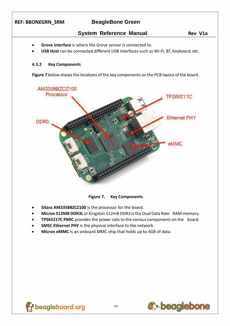
4.3.2 Key Components
Figure 7 below shows the locations of the key components on the PCB layout of the board.
Figure 7. Key Components
Sitara AM3358BZCZ100 is the processor for the board.
Micron 512MB DDR3L or Kingston 512mB DDR3 is the Dual Data Rate RAM memory.
TPS65217C PMIC provides the power rails to the various components on the board.
SMSC Ethernet PHY is the physical interface to the network.
Micron eMMC is an onboard MMC chip that holds up to 4GB of data.

REF: BBONEGRN_SRM BeagleBone Green
System Reference Manual Rev V1a
15
5.0 BeagleBone Green High Level Specification
This section provides the high level specification of the BeagleBone Green.
5.1 Block Diagram
Figure 8 below is the high level block diagram of the BeagleBone Green.
Figure 8. BeagleBone Green Block diagram

REF: BBONEGRN_SRM BeagleBone Green
System Reference Manual Rev V1a
16
5.2 Processor
Sitara AM3358BZCZ100
5.3 Memory
Described in the following sections are the three memory devices found on the board.
5.3.1 512MB DDR3L
A single 256Mb x16 DDR3L 4Gb (512MB) memory device is used. The memory used is is
one of two devices:
- MT41K256M16HA-125 from Micron
- D2516EC4BXGGB from Kingston
It will operate at a clock frequency of 400MHz yielding an effective rate of 800MHZ on the
DDR3L bus allowing for 1.6GB/S of DDR3L memory bandwidth.
5.3.2 4KB EEPROM
A single 4KB EEPROM is provided on I2C0 that holds the board information. This
information includes board name, serial number, and revision information. This is the not
the same as the one used on the original BeagleBone. The device was changed for cost
reduction reasons. It has a test point to allow the device to be programmed and otherwise
to provide write protection when not grounded.
5.3.3 4GB Embedded MMC
A single 4GB embedded MMC (eMMC) device is on the board. The device connects to the
MMC1 port of the processor, allowing for 8bit wide access. Default boot mode for the
board will be MMC1 with an option to change it to MMC0, the SD card slot, for booting
from the SD card as a result of removing and reapplying the power to the board. Simply
pressing the reset button will not change the boot mode. MMC0 cannot be used in 8Bit
mode because the lower data pins are located on the pins used by the Ethernet port. This
does not interfere with SD card operation but it does make it unsuitable for use as an
eMMC port if the 8 bit feature is needed.
5.3.4 MicroSD Connector
The board is equipped with a single micro SD connector to act as the secondary boot
source for the board and, if selected as such, can be the primary boot source. The
connector will support larger capacity micro SD cards. The micro SD card is not provided

REF: BBONEGRN_SRM BeagleBone Green
System Reference Manual Rev V1a
17
with the board. Booting from MMC0 will be used to flash the eMMC in the production
environment or can be used by the user to update the SW as needed.
5.3.5 Boot Modes
As mentioned earlier, there are four boot modes:
eMMC Boot...This is the default boot mode and will allow for the fastest boot time
and will enable the board to boot out of the box using the pre-flashed OS image
without having to purchase an microSD card or an microSD card writer.
SD Boot...This mode will boot from the microSD slot. This mode can be used to
override what is on the eMMC device and can be used to program the eMMC when
used in the manufacturing process or for field updates.
Serial Boot...This mode will use the serial port to allow downloading of the software
direct. A separate USB to serial cable is required to use this port.
USB Boot...This mode supports booting over the USB port.
Software to support USB and serial boot modes is not provided by beagleboard.org.
Please contact TI for support of this feature.
A switch is provided to allow switching between the modes.
Holding the boot switch down during a removal and reapplication of power without
a microSD card inserted will force the boot source to be the USB port and if nothing
is detected on the USB client port, it will go to the serial port for download.
Without holding the switch, the board will boot try to boot from the eMMC. If it is
empty, then it will try booting from the microSD slot, followed by the serial port, and
then the USB port.
If you hold the boot switch down during the removal and reapplication of power to
the board, and you have a microSD card inserted with a bootable image, the board
will boot from the microSD card.
NOTE: Pressing the RESET button on the board will NOT result in a change of the boot
mode. You MUST remove power and reapply power to change the boot mode. The boot
pins are sampled during power on reset from the PMIC to the processor. The reset button
on the board is a warm reset only and will not force a boot mode change.
5.4 Power Management
The TPS65217C power management device is used along with a separate LDO to provide
power to the system. The TPS65217C version provides for the proper voltages required
for the DDR3L. This is the same device as used on the original BeagleBone with the
exception of the power rail configuration settings which will be changed in the internal
EEPROM to the TPS65217C to support the new voltages.

REF: BBONEGRN_SRM BeagleBone Green
System Reference Manual Rev V1a
18
DDR3L requires 1.5V instead of 1.8V on the DDR2 as is the case on the original BeagleBone.
The 1.8V regulator setting has been changed to 1.5V for the DDR3L. The LDO3 3.3V rail
has been changed to 1.8V to support those rails on the processor. LDO4 is still 3.3V for the
3.3V rails on the processor. An external LDOTLV70233 provides the 3.3V rail for the rest of
the board.
5.5 PC USB Interface
The board has a Micro USB connector that connects the USB0 port to the processor. This
is the most commonly used connector.
5.6 Serial Debug Port
Serial debug is provided via UART0 on the processor via a single 1x6 pin header. In order
to use the interface a USB to TTL adapter will be required. The header is compatible with
the one provided by FTDI and can be purchased for about $12 to $20 from various sources.
Signals supported are TX and RX. None of the handshake signals are supported.
5.7 USB1 Host Port
On the board is a single USB Type A female connector with full LS/FS/HS Host support that
connects to USB1 on the processor. The port can provide power on/off control and up to
500mA of current at 5V. Under USB power, the board will not be able to supply the full
500mA, but should be sufficient to supply enough current for a lower power USB device
supplying power between 50 to 100mA.
You can use a wireless keyboard/mouse configuration or you can add a HUB for standard
keyboard and mouse interfacing.
5.8 Power Sources
The board can be powered from three different sources:
USB port on a PC
A power supply with a USB connector.
Expansion connectors
The USB cable is shipped with each board. This port is limited to 500mA by the Power
Management IC. It is possible to change the settings in the TPS65217C to increase this
current, but only after the initial boot. And, at that point the PC most likely will complain,
but you can also use a dual connector USB cable to the PC to get to 1A.
The power supply is not provided with the board but can be easily obtained from

REF: BBONEGRN_SRM BeagleBone Green
System Reference Manual Rev V1a
19
numerous sources. A 1A supply is sufficient to power the board, but if there is a cape
plugged into the board or you have a power hungry device or hub plugged into the host
port, then more current may needed from the P9 Expansion connector VDD_5V pin.
Power routed to the board via the expansion header could be provided from power
derived on a cape.
5.9 Reset Button
When pressed and released, causes a reset of the board. The reset button used on the
BeagleBone Black is a little larger than the one used on the original BeagleBone. It has also
been moved out to the edge of the board so that it is more accessible.
5.10 Power Button
A power button is provided near the reset button close to the Ethernet connector. This
button takes advantage of the input to the PMIC for power down features. While a lot of
capes have a button, it was decided to add this feature to the board to ensure everyone
had access to some new features. These features include:
Interrupt is sent to the processor to facilitate an orderly shutdown to save files and
to un-mount drives.
Provides ability to let processor put board into a sleep mode to save power.
Can alert processor to wake up from sleep mode and restore state before sleep was
entered.
If you hold the button down longer than 8 seconds, the board will power off if you release
the button when the power LED turns off. If you continue to hold it, the board will power
back up completing a power cycle.
We recommend that you use this method to power down the board. It will also help
prevent contamination of the SD card or the eMMC.
If you do not remove the power jack, you can press the button again and the board will
power up.
5.11 Indicators
There are a total of five blue LEDs on the board.
One blue power LED indicates that power is applied and the power management IC
is up. If this LED flashes when applying power, it means that an excess current flow
was detected and the PMIC has shut down.

REF: BBONEGRN_SRM BeagleBone Green
System Reference Manual Rev V1a
20
Four blue LEDs that can be controlled via the SW by setting GPIO pins.
In addition, there are two LEDs on the RJ45 to provide Ethernet status indication. One is
yellow (100M Link up if on) and the other is green (Indicating traffic when flashing).
5.12 CTI JTAG Header
A place for an optional 20 pin CTI JTAG header is provided on the board to facilitate the
SW development and debugging of the board by using various JTAG emulators. This
header is not supplied standard on the board. To use this, a connector will need to be
soldered onto the board.
If you need the JTAG connector you can solder it on yourself. No other components are
needed. The connector is made by Samtec and the part number is FTR-110-03-G-D-06.
You can purchase it from http://www.digikey.com/.
5.13 Grove Interfaces
There are two Grove connectors on the board:
I2C…The J4 connector is I2C interface. It accesses to the processor’s I2C2 interface
and also connect with the P9 expansion header’s I2C2 pins. The Grove I2C connector
is for the connection of Grove sensors with I2C interface.
Uart…The J5 connector is UART interface. It accesses to the processor’s UART2
interface and also connect with the P9 expansion header’s UART2 pins. The Grove
UART connector is for the connection of Grove sensors with UART interface.
Because of I2C and UART Interface can be setup to GPIO , the Groves with Digital interface
are supported for both Connectors.
If you want to connect more Grove modules , see Grove Cape for BeagleBone Series
innovated by Seeedstudio:
http://www.seeedstudio.com/depot/Grove-Cape-for-BeagleBone-Series-p-1718.html
For more information about Grove system, please visit:
http://www.seeedstudio.com/wiki/Grove_System
5.14 Cape Board Support
The BeagleBone Green has the ability to accept up to four expansion boards or capes that
can be stacked onto the expansion headers. The word cape comes from the shape of the
board as it is fitted around the Ethernet connector on the main board. This notch acts as
a key to ensure proper orientation of the cape.

REF: BBONEGRN_SRM BeagleBone Green
System Reference Manual Rev V1a
21
The majority of capes designed for the original BeagleBone or BeagleBone Black will work
on the BeagleBone Green. The two main expansion headers will be populated on the
board. There are a few exceptions where certain capabilities may not be present or are
limited to the BeagleBone Green. These include:
GPMC bus may NOT be available due to the use of those signals by the eMMC. If the
eMMC is used for booting only and the file system is on the microSD card, then these
signals could be used.
Another option is to use the microSD or serial boot modes and not use the eMMC.
The power expansion header is not on the BeagleBone Green so those functions are
not supported.
5.15 Expansion Board External Power
A cape can have a jack or terminals to bring in whatever voltages may be needed by that
board. Care should be taken not to let this voltage be fed back into any of the expansion
header pins.
It is possible to provide 5V to the main board from an expansion board. By supplying a 5V
signal into the VDD_5V rail, the main board can be supplied. This voltage must not exceed
5V. You should not supply any voltage into any other pin of the expansion connectors.
Based on the board design, this rail is limited to 1A per pin to the BeagleBone Green.
There are several precautions that need to be taken when working with the expansion
headers to prevent damage to the board.
1) Do not apply any voltages to any I/O pins when the board is not powered on.
2) Do not drive any external signals into the I/O pins until after the VDD_3V3B rail is up.
3) Do not apply any voltages that are generated from external sources.
4) If voltages are generated from the VDD_5V signal, those supplies must not become
active until after the VDD_3V3B rail is up.
5) If you are applying signals from other boards into the expansion headers, make sure you
power the board up after you power up the BeagleBone Green or make the connections
after power is applied on both boards.
Powering the processor via its I/O pins can cause damage to the processor.

REF: BBONEGRN_SRM BeagleBone Green
System Reference Manual Rev V1a
22
6.0 BeagleBone Green Mechanical
6.1 Dimensions and Weight
Size: 3.5” x 2.15” (86.36mm x 53.34mm)
Max height: .187” (4.76mm)
PCB Layers: 6 .062”
PCB thickness: Yes
RoHS Compliant: 1.4 oz

REF: BBONEGRN_SRM BeagleBone Green
System Reference Manual Rev V1a
23
6.2 Board Dimensions
Figure 9. Board Dimensions

REF: BBONEGRN_SRM BeagleBone Green
System Reference Manual Rev V1a
24
7.0 Pictures
Figure 10. Top Side

REF: BBONEGRN_SRM BeagleBone Green
System Reference Manual Rev V1a
25
Figure 11. Bottom Side

REF: BBONEGRN_SRM BeagleBone Green
System Reference Manual Rev V1a
26
8.0 Support Information
All support for this design is through the BeagleBoard.org community at:
or
http://beagleboard.org/discuss.
8.1 Hardware Design
Design documentation can be found on the eMMC of the board under the
documents/hardware directory when connected using the USB cable. Provided there is:
Schematic in PDF
Schematic in OrCAD (Cadence Design Entry CIS 16.3)
PCB Gerber
PCB Layout File (Allegro)
Bill of Material
System Reference Manual (This document).
This directory is not always kept up to date in every SW release due to the frequency of
changes of the SW. The best solution is to download the files from the Circuitco WIKI at
http://www.seeedstudio.com/wiki/beaglebone_green
8.2 Software Updates
It is a good idea to always use the latest software. Instructions for how to update your
software to the latest version can be found at:
http://www.seeedstudio.com/wiki/beaglebone_green
9.0 Document revision