BeagleBone Battery RevA Srm
24
BeagleBone Battery Cape System Reference Manual Revision A Page 1 of 24 BeagleBone Battery Cape Rev A System Reference Manual Revision A June 20th, 2012
-
Upload
pradeep-reddy -
Category
Documents
-
view
227 -
download
0
description
beagle
Transcript of BeagleBone Battery RevA Srm

BeagleBone Battery Cape System Reference Manual Revision A
Page 1 of 24
BeagleBone Battery Cape Rev A
System Reference Manual
Revision A June 20th, 2012

BeagleBone Battery Cape System Reference Manual Revision A
Page 2 of 24
THIS DOCUMENT
This work is licensed under the Creative Commons Attribution-Share Alike 3.0 Unported License. To view a copy of this license, visit http://creativecommons.org/licenses/by-sa/3.0/ or send a letter to Creative Commons, 171 Second Street, Suite 300, San Francisco, California, 94105, USA. All derivative works are to be attributed to BeagleBoardtoys.com. For more information, see http://creativecommons.org/license/results-one?license_code=by-sa For any questions, concerns, or issues submit them to [email protected]
BEAGLEBONE BATTERY CAPE DESIGN These design materials referred to in this document are *NOT SUPPORTED* and DO NOT constitute a reference design. Only “community” support is allowed via resources at Beagleboardtoys.com/support THERE IS NO WARRANTY FOR THE DESIGN MATERIALS, TO THE EXTENT PERMITTED BY APPLICABLE LAW. EXCEPT WHEN OTHERWISE STATED IN WRITING THE COPYRIGHT HOLDERS AND/OR OTHER PARTIES PROVIDE THE DESIGN MATERIALS “AS IS” WITHOUT WARRANTY OF ANY KIND, EITHER EXPRESSED OR IMPLIED, INCLUDING, BUT NOT LIMITED TO, THE IMPLIED WARRANTIES OF MERCHANTABILITY AND

BeagleBone Battery Cape System Reference Manual Revision A
Page 3 of 24
FITNESS FOR A PARTICULAR PURPOSE. THE ENTIRE RISK AS TO THE QUALITY AND PERFORMANCE OF THE DESIGN MATERIALS IS WITH YOU. SHOULD THE DESIGN MATERIALS PROVE DEFECTIVE, YOU ASSUME THE COST OF ALL NECESSARY SERVICING, REPAIR OR CORRECTION. We mean it; these design materials may be totally unsuitable for any purposes.

BeagleBone Battery Cape System Reference Manual Revision A
Page 4 of 24
BeagleBoardToys provides the enclosed product(s) under the following conditions: This evaluation board/kit is intended for use for ENGINEERING DEVELOPMENT, DEMONSTRATION, OR EVALUATION PURPOSES ONLY and is not considered by BeagleBoardtoys.com to be a finished end-product fit for general consumer use. Persons handling the product(s) must have electronics training and observe good engineering practice standards. As such, the goods being provided are not intended to be complete in terms of required design-, marketing-, and/or manufacturing-related protective considerations, including product safety and environmental measures typically found in end products that incorporate such semiconductor components or circuit boards. This evaluation board/kit does not fall within the scope of the European Union directives regarding electromagnetic compatibility, restricted substances (RoHS), recycling (WEEE), FCC, CE or UL, and therefore may not meet the technical requirements of these directives or other related directives. Should this evaluation board/kit not meet the specifications indicated in the User’s Guide, the board/kit may be returned within 30 days from the date of delivery for a full refund. THE FOREGOING WARRANTY IS THE EXCLUSIVE WARRANTY MADE BY SELLER TO BUYER AND IS IN LIEU OF ALL OTHER WARRANTIES, EXPRESSED, IMPLIED, OR STATUTORY, INCLUDING ANY WARRANTY OF MERCHANTABILITY OR FITNESS FOR ANY PARTICULAR PURPOSE. The user assumes all responsibility and liability for proper and safe handling of the goods. Further, the user indemnifies BeagleBoardtoys.com from all claims arising from the handling or use of the goods. Due to the open construction of the product, it is the user’s responsibility to take any and all appropriate precautions with regard to electrostatic discharge. EXCEPT TO THE EXTENT OF THE INDEMNITY SET FORTH ABOVE, NEITHER PARTY SHALL BE LIABLE TO THE OTHER FOR ANY INDIRECT, SPECIAL, INCIDENTAL, OR CONSEQUENTIAL DAMAGES. BeagleBoardtoys.com currently deals with a variety of customers for products, and therefore our arrangement with the user is not exclusive. BeagleBoardtoys.com assumes no liability for applications assistance, customer product design, software performance, or infringement of patents or services described herein. Please read the User’s Guide and, specifically, the Warnings and Restrictions notice in the User’s Guide prior to handling the product. This notice contains important safety information about temperatures and voltages. For additional information on BeagleBoardtoys.com environmental and/or safety programs, please contact visit BeagleBoardtoys.com. No license is granted under any patent right or other intellectual property right of BeagleBoard.org covering or relating to any machine, process, or combination in which such BeagleBoardtoys.com products or services might be or are used. Mailing Address:
Beagleboardtoys.com 1380 Presidential Dr. #100 Richardson, TX 75081 U.S.A.

BeagleBone Battery Cape System Reference Manual Revision A
Page 5 of 24
WARRANTY: The BeagleBone Battery Cape is warranted against defects in materials and workmanship for a period of 90 days from purchase. This warranty does not cover any problems occurring as a result of improper use, modifications, exposure to water, excessive voltages, abuse, or accidents. All boards will be returned via standard mail if an issue is found. If no issue is found or express return is needed, the customer will pay all shipping costs.
Before returning the board, please visit Beagleboardtoys.com/support To return a defective board, please request an RMA at http://www.beagleboardtoys.com/support/rma

BeagleBone Battery Cape System Reference Manual Revision A
Page 6 of 24
Table of Contents FIGURES ...................................................................................................................................................... 7
TABLES ........................................................................................................................................................ 7
1.0 INTRODUCTION............................................................................................................................... 9
2.0 CHANGE HISTORY .........................................................................................................................10
2.1 CHANGE HISTORY ............................................................................................................................10
3.0 BEAGLEBONE BATTERY CAPE OVERVIEW ..........................................................................11
3.1 DESCRIPTIONS..................................................................................................................................11 3.2 IN THE BOX .....................................................................................................................................12 3.3 GETTING STARTED ...........................................................................................................................12 3.4 REPAIRS ...........................................................................................................................................12
4.0 FEATURES AND SPECIFICATIONS ............................................................................................13
4.1 KEY COMPONENT LOCATIONS .........................................................................................................14 4.2 BATTERY HOLDERS .........................................................................................................................15 4.3 INDICATORS .....................................................................................................................................15 4.4 EXPANSION CONNECTORS ................................................................................................................15 4.5 SWITCH ............................................................................................................................................15 4.6 MECHANICAL SPECIFICATIONS ........................................................................................................16 4.7 ELECTRICAL SPECIFICATIONS ..........................................................................................................16
5.0 SYSTEM ARCHITECTURE AND DESIGN ..................................................................................17
5.1 SYSTEM BLOCK DIAGRAM ...............................................................................................................17 5.2 VBAT ..............................................................................................................................................18 5.3 BOOST CONVERTER .........................................................................................................................20 5.4 EEPROM ........................................................................................................................................21
5.4.1 EEPROM Address .................................................................................................................21 5.4.2 I2C Bus ..................................................................................................................................22
6.0 MECHANICAL INFORMATION ............................ .......................................................................23
7.0 DESIGN MATERIALS .....................................................................................................................24
BeagleBone Battery Cape System Reference Manual Revision A
Page 7 of 24
Figures Figure 1. The BeagleBone Battery Cape ...................................................................... 11 Figure 2. Battery Cape key components ...................................................................... 14 Figure 3. BeagleBone Battery Cape High Level Block Diagram ................................ 17 Figure 4. Battery Holder Configuration ....................................................................... 18
Figure 5. Battery voltage level divider ......................................................................... 19 Figure 6. Boost converter circuit .................................................................................. 20 Figure 7. BeagleBone Battery Cape EEPROM ............................................................ 21 Figure 8. BeagleBone LCD3 Cape Dimensions Drawing ............................................ 23
Tables Table 1. Change History ............................................................................................. 10 Table 2. BeagleBone Battery Cape Features .............................................................. 13
BeagleBone Battery Cape System Reference Manual Revision A
Page 8 of 24
NOTES

BeagleBone Battery Cape System Reference Manual Revision A
Page 9 of 24
1.0 Introduction This document is the System Reference Manual for the BeagleBone Battery Cape, an add-on board for the BeagleBone. This document is intended as a guide to assist anyone purchasing or who are considering purchasing the board to understand the overall design and usage of the BeagleBone Battery Cape from the system level perspective. The design is subject to change without notice as we will work to keep improving the design as the product matures. The key sections in this document are: Section 2.0 – Change History
Provides tracking for the changes made to the System Reference Manual. Section 3.0 – Overview This is a high level overview of the BeagleBone Battery Cape. Section 4.0 – Features and Specification Provided here are the features and electrical specifications of the board. Section 5.0 – System Architecture and Design
This section provides information on the overall architecture and design of the BeagleBone Battery Cape. This is a very detailed section that goes into the design of each circuit on the board.
Section 6.0 – Mechanical Information is provided here on the dimensions of the BeagleBone Battery Cape. Section 7.0 – Design Materials
This section provides information on where to get the design files.

BeagleBone Battery Cape System Reference Manual Revision A
Page 10 of 24
2.0 Change History 2.1 Change History Table 1 tracks the changes made for each revision of this document.
Table 1. Change History
Rev Changes Date By A Initial release. 06/20/2012 BBT
.

BeagleBone Battery Cape System Reference Manual Revision A
Page 11 of 24
3.0 BeagleBone Battery Cape Overview 3.1 Descriptions The BeagleBone Battery Cape provides a portable power solution for BeagleBone boards and its Capes. This Cape provides 5V power supply to the BeagleBone using 4 Lithium AA battery cells. Power will be provided to BeagleBone’s VDD_5V power rail as soon as battery cells are installed. The BeagleBone Battery cape is also equipped with a power switch, a power indicator LED, and an EEPROM for muxing configuration. Figure 1 below is a picture of the board.
Figure 1. The BeagleBone Battery Cape
BeagleBone Battery Cape System Reference Manual Revision A
Page 12 of 24
3.2 In The Box The final packaged BeagleBone Battery Cape Rev A product will contain the following items:
- 1 BeagleBone Battery Cape - 1 Wiki information card
3.3 Getting Started Following the instructions below to start using your BeagleBone Battery Cape:
1. Mount the Battery Cape on the BeagleBone. 2. Install 4 AA Lithium battery cells to the battery holders. Each holder should only
hold one cell. 3. As soon as battery cells are installed, the BeagleBone will power on.
• Note: Due to holder configuration, BeagleBone will power on as soon as two battery cells on one wing are installed. This is normal. You can keep installing battery cells on the other wing
4. The Power LED on the Battery Cape and BeagleBone should be lit. You can start using your BeagleBone. 3.4 Repairs If you feel the board is in need of repair, follow the RMA Request process found at http://www.beagleboardtoys.com/support/rma
Do not send the board in for repair until an RMA authorization has been provided.
Do not return the board to the distributor unless you want to get a refund. You must get authorization from the distributor before returning the board.

BeagleBone Battery Cape System Reference Manual Revision A
Page 13 of 24
4.0 Features and Specifications This section covers the specifications of the BeagleBone Battery Cape and provides a high level description of the major components and interfaces that make up the board. Table 2 provides a list of the BeagleBone Battery Cape’s features.
Table 2. BeagleBone Battery Cape Features
Feature Power Supply 3.0V via Lithium battery cells
Holder s 4 AA battery holders
PCB 3.55" x 3.40" 2 layers
Indicators Power LED
EEPROM Cape Address EEPROM
Expansion Connector Two 46-position connectors
10-position connector

BeagleBone Battery Cape System Reference Manual Revision A
Page 14 of 24
4.1 Key Component Locations Figure 2 below shows the top side locations of key components on the PCB layout of the BeagleBone Battery Cape:
Figure 2. Battery Cape key components

BeagleBone Battery Cape System Reference Manual Revision A
Page 15 of 24
4.2 Battery Holders The BeagleBone Battery Cape features 4 battery holders distributed equally on each side of PCB. Holders on each wing are mounted on the opposite sides of the PCB. These holders are the 2460 model and provided by Keystone. Each holder can hold a single AA battery cell. Four Battery holders are configured as 2 parallel sets on both wings of the Battery Cape. Each set consists of 2 holders populated on opposite sides of the PCB. The holders in each set are connected in series. Thus, if both holders in one set are installed with battery cells, 5V will be provided to power rail VDD_5V right away. Installing the other set will provide more current to the boost converter. 4.3 Indicators There is one indicator on the board and this indicator is the Power LED D2. The Power LED indicates that power from battery cells is applied to the VDD_5V power rail, which is used to power the BeagleBone. The Power LED is located between the Power switch and the 10-position connector. 4.4 Expansion Connectors The BeagleBone Battery Cape uses a standard stackable connector set for BeagleBone capes. This set is composed of two 46-position connectors and one 10-position connector. These connectors can be used to stack on a BeagleBone or be stacked by another cape. 4.5 Switch There is a Power switch on the board next to the 10-position expansion connector. This button is a standard tactile switch and mounted at right angle. The PWR_BUT signal, which can also be accessed at expansion connector J2, is connected to the Power button. When pressed and held for 10 seconds, the Power button will turn off the mounted BeagleBone.
BeagleBone Battery Cape System Reference Manual Revision A
Page 16 of 24
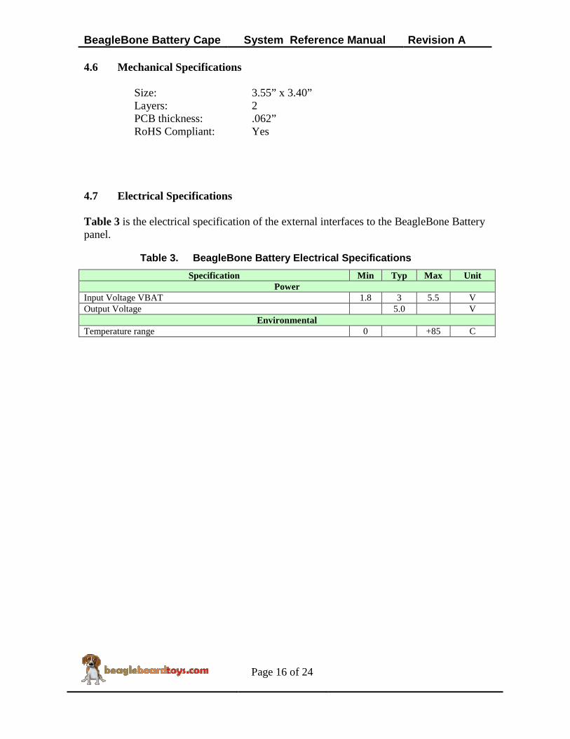
4.6 Mechanical Specifications
Size: 3.55” x 3.40” Layers: 2 PCB thickness: .062”
RoHS Compliant: Yes 4.7 Electrical Specifications Table 3 is the electrical specification of the external interfaces to the BeagleBone Battery panel.
Table 3. BeagleBone Battery Electrical Specifications
Specification Min Typ Max Unit Power
Input Voltage VBAT 1.8 3 5.5 V Output Voltage 5.0 V
Environmental Temperature range 0 +85 C
BeagleBone Battery Cape System Reference Manual Revision A
Page 17 of 24
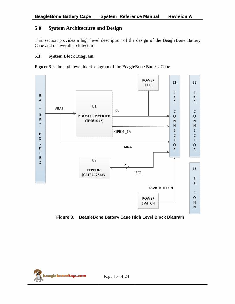
5.0 System Architecture and Design This section provides a high level description of the design of the BeagleBone Battery Cape and its overall architecture. 5.1 System Block Diagram Figure 3 is the high level block diagram of the BeagleBone Battery Cape.
J1
E
X
P
C
O
N
N
E
C
T
O
R
U1
BOOST CONVERTER
(TPS61032)
U2
EEPROM
(CAT24C256W)I2C2
2
POWER
SWITCH
POWER
LED
J3
B
L
C
O
N
N
B
A
T
T
E
R
Y
H
O
L
D
E
R
S
VBAT5V
J2
E
X
P
C
O
N
N
E
C
T
O
R
PWR_BUTTON
AIN4
GPIO1_16
Figure 3. BeagleBone Battery Cape High Level Block Diagram

BeagleBone Battery Cape System Reference Manual Revision A
Page 18 of 24
5.2 VBAT The BeagleBone Battery Cape is powered from 4 single Lithium AA battery cells. These cells will provide power to the VBAT power rail, which is the input to the boost converter. When installed, 4 battery cells are connected as two sets in parallel; each sets consists of two cells in series. Since the nominal voltage of each AA cell is 1.5V, two cells in series will provide a maximum voltage of 3.0V to VBAT. By having two series groups of battery cells in parallel, more current can be supplied to the boost converter. Figure 4 shows the battery holder configuration.
Figure 4. Battery Holder Configuration The voltage level of VBAT can be monitored by an analog input AIN4 on expansion connector J2. Since the analog inputs on BeagleBone are at 1.8V level, a voltage divider is required to bring VBAT to a third of its voltage level. Therefore, AIN4 will read 1V when VBAT is at its maximum voltage level (3V). Figure 5 display the voltage divider for battery voltage level input.

BeagleBone Battery Cape System Reference Manual Revision A
Page 19 of 24
Figure 5. Battery voltage level divider

BeagleBone Battery Cape System Reference Manual Revision A
Page 20 of 24
5.3 Boost Converter The Battery Cape uses TPS61032 to generate a stable output voltage to power rail VDD_5V of BeagleBone. TPS61032 provides high efficient power conversion and is capable of delivering output current up to 1A at 5V at a supply voltage down to 1.8V. The converter can be disabled to minimize battery drain. During shutdown, the load is completely disconnected from the battery. A low-EMI mode is implemented to reduce ringing and, in effect, lower radiated electromagnetic energy when the converter enters the discontinuous conduction mode. The device is put into operation when the EN pin is pulled high. This pin on the Battery Cape is connected to VBAT; therefore, the boost converter will start operation as soon as VBAT reaches 3.0V. The internal start-up cycle will start with the pre-charge phase. During this phase, the output capacitor is charged to a value close to the input voltage. Until the output voltage is reached, the boost switch current limit is set to 40% of its nominal value to avoid high peak currents at battery during startup. Output voltage of the boost converter is determined by voltage divider resistors R4 and R9. The maximum output voltage is 5.5V. In this case, R4 and R9 are chosen to be 180K and 1.74M respectively to set the output voltage to be 5.35V. 350mV will be dropped across Schottky diode D1 to provide 5V to power rail VDD_5V. The SYNC pin is connected to Ground to enable the power save mode. The LBI input is pulled low to disable the low battery detector circuit. The LBO output, which is mapped to GPIO1_16, will stay at high impedance. Figure 6 is the boost converter circuit.
Figure 6. Boost converter circuit

BeagleBone Battery Cape System Reference Manual Revision A
Page 21 of 24
5.4 EEPROM The BeagleBone Battery Cape has an EEPROM containing information that will allow the SW to identify the board and to configure the expansion headers pins as needed. EEPROMs are required for all Capes sold in order for them to operate correctly when plugged in the BeagleBone. The EEPROM used on this cape is the same one as is used on the BeagleBone, a CAT24C256. The CAT24C256 is a 256 kb Serial CMOS EEPROM, internally organized as 32,768 words of 8 bits each. It features a 64-byte page write buffer and supports the Standard (100 kHz), Fast (400 kHz) and Fast-Plus (1 MHz) I2C protocol. Figure 7 is the design of the EEPROM circuit.
Figure 7. BeagleBone Battery Cape EEPROM
5.4.1 EEPROM Address In order for each Cape to have a unique address, a board ID scheme is used that sets the address to be different depending on the order in which it is stacked onto the main board. A two position dipswitch or jumpers is used to set the address pins of the EEPROM. It is the responsibility of user to set the proper address for each board. Address line A2 is always tied high. This sets the allowable address range for the expansion cards to 0x54 to 0x57.All other I2C addresses can be used by the user in the design of their Capes. But, these addresses must not be used other than for the board EEPROM information.
BeagleBone Battery Cape System Reference Manual Revision A
Page 22 of 24
5.4.2 I2C Bus The EEPROMs on each expansion board is connected to I2C2. For this reason I2C2 must always be left connected and should not be changed by SW to remove it from the expansion header pin mux. The I2C signals require pull-up resistors. Each board must have a 5.6K resistor on these signals. With four resistors this will be an affective resistance of 1.4K if all Capes were installed.

BeagleBone Battery Cape System Reference Manual Revision A
Page 23 of 24
6.0 Mechanical Information This section provides information on the mechanical aspect of the BeagleBone Battery Cape. Figure 8 is the dimensions of the BeagleBone Battery Cape.
Figure 8. BeagleBone LCD3 Cape Dimensions Drawing

BeagleBone Battery Cape System Reference Manual Revision A
Page 24 of 24
7.0 Design Materials Design information can be found at BeagleBoardToys wiki: http://beagleboardtoys.com/wiki/index.php?title=BeagleBone_Battery Provided there is:
- Schematic in PDF - Schematic in OrCAD - Manufacturing files
o PCB Gerber o PCB Layout (Allegro)
- Bill of Materials - System Reference Manual (This document)
These design materials are *NOT SUPPORTED* and DO NOT constitute a reference design. Only “community” support is allowed via resources at BeagleBoard.org/discuss. THERE IS NO WARRANTY FOR THE DESIGN MATERIALS, TO THE EXTENT PERMITTED BY APPLICABLE LAW. EXCEPT WHEN OTHERWISE STATED IN WRITING THE COPYRIGHT HOLDERS AND/OR OTHER PARTIES PROVIDE THE DESIGN MATERIALS “AS IS” WITHOUT WARRANTY OF ANY KIND, EITHER EXPRESSED OR IMPLIED, INCLUDING, BUT NOT LIMITED TO, THE IMPLIED WARRANTIES OF MERCHANTABILITY AND FITNESS FOR A PARTICULAR PURPOSE. THE ENTIRE RISK AS TO THE QUALITY AND PERFORMANCE OF THE DESIGN MATERIALS IS WITH YOU. SHOULD THE DESIGN MATERIALS PROVE DEFECTIVE, YOU ASSUME THE COST OF ALL NECESSARY SERVICING, REPAIR OR CORRECTION. We mean it, these design materials may be totally unsuitable for any purposes.