Beacon in a Box - ogdenarc.orgogdenarc.org/downloads/Beacon by N7JS.pdf · Beacon in a Box A...
4
Beacon in a Box A 10-Meter Auto Beacon By Jim Southwick, N7JS So the sunspot cycle's bottoming out and there won't be any dx on 10 meters unti1 2009, right? Wrong! There are always occasional openings on 10-meters, even at the bottom of the sunspot cycle, due to sporadic-E propagation. But how do you know about them? The answer, in a word: beacons. Here's how to build one... I've always been fascinated with HF beacons. Listening for them is a great way to find out if a particular band is propagating and from what direction. The 10-meter band especially interests me, because the FCC will allow a licensed operator to set up an unattended beacon. However, care should be exercised to check on your beacon regularly. The agreed upon segment is from 28.200-28.300 MHz. When the band is open, you generally can hear beacons throughout this range from all parts of the world using very little power and often a simple vertical or dipole antenna. Conversely, you can also transmit a beacon to all parts of the world with the same criteria. My goal with this project was to forgo dedicating an HF radio for the beacon and instead make a nice all-in- one unit that could fit in your hand and be portable, yet have the look of a nice little base-station unit. I also wanted to keep the cost for everything under $100. This project features a control interface that will store the CW message and key the transmitter automatically at intervals you determine. I love bells and whistles. Therefore, for the front of the beacon unit (photo A), I incorporated an RF meter and four switches, one to turn the system on and off, another to change between two different frequencies (in case one is busy or taken), a third to turn the monitor speaker on and off (who wants to hear that 24 hours a day?), and the fourth to turn on a light for illuminating the meter. I needed the last item to save power in case of portable use. Photo A- Front view of the beacon transmitter. A label machine gives everything a professional, finished look. (Photos by Leah Hogsten) On the back of the case (photo B) I have a power jack that can be used for a 12-volt power supply or auto- battery hookup, but the unit is also able to run 9-volt portable (complete with a 9-volt battery holder). I also have a DB9 connector for connecting to a computer to easily program the beacon message and intervals. I also decided to use an SO239 for the antenna (rather than an RCA or BNC jack). At this frequency, we will be just fine with this much more convenient connector. This also allows you to connect a portable back of set antenna if you desire, for a complete all in one setup. For portable use I simply purchased a back of set CB antenna from Radio Shack. The Miracle Whip antenna would also work nicely in this case. Well, with all the external hardware planned out, it was time to plan out the guts for this item. Namely a beacon interface and a transmitter. So let's begin! We'll start off with the beacon interface, called the Freakin' Beacon.
Transcript of Beacon in a Box - ogdenarc.orgogdenarc.org/downloads/Beacon by N7JS.pdf · Beacon in a Box A...

Beacon in a Box
A 10-Meter Auto Beacon
By Jim Southwick, N7JS
So the sunspot cycle's bottoming out and there won't be any dx on 10 meters unti1 2009, right? Wrong! There are always
occasional openings on 10-meters, even at the bottom of the sunspot cycle, due to sporadic-E propagation. But how do
you know about them? The answer, in a word: beacons. Here's how to build one...
I've always been fascinated with HF beacons. Listening for them is a great way to find out if a particular
band is propagating and from what direction. The 10-meter band especially interests me, because the FCC will allow a licensed operator to set up an unattended beacon. However, care should be exercised to check on your beacon regularly. The agreed upon segment is from 28.200-28.300 MHz. When the band is open, you generally can hear beacons throughout this range from all parts of the world using very little power and often a simple vertical or dipole antenna. Conversely, you can also transmit a beacon to all parts of the world with the same criteria.
My goal with this project was to forgo dedicating an HF radio for the beacon and instead make a nice all-in-one unit that could fit in your hand and be portable, yet have the look of a nice little base-station unit. I also wanted to keep the cost for everything under $100.
This project features a control interface that will store the CW message and key the transmitter automatically at intervals you determine. I love bells and whistles. Therefore, for the front of the beacon unit (photo A), I incorporated an RF meter and four switches, one to turn the system on and off, another to change between two different frequencies (in case one is busy or taken), a third to turn the monitor speaker on and off (who wants to hear that 24 hours a day?), and the fourth to turn on a light for illuminating the meter. I needed the last item to save power in case of portable use.
Photo A- Front view of the beacon transmitter. A label machine gives everything a professional, finished look. (Photos by Leah Hogsten)
On the back of the case (photo B) I have a power jack that can be used for a 12-volt power supply or auto-
battery hookup, but the unit is also able to run 9-volt portable (complete with a 9-volt battery holder). I also have a DB9 connector for connecting to a computer to easily program the beacon message and intervals. I also decided to use an SO239 for the antenna (rather than an RCA or BNC jack). At this frequency, we will be just fine with this much more convenient connector. This also allows you to connect a portable back of set antenna if you desire, for a complete all in one setup. For portable use I simply purchased a back of set CB antenna from Radio Shack. The Miracle Whip antenna would also work nicely in this case.
Well, with all the external hardware planned out, it was time to plan out the guts for this item. Namely a beacon interface and a transmitter. So let's begin! We'll start off with the beacon interface, called the Freakin' Beacon.

Photo B- Rear view of the beacon transmitter. The 9-volt battery clip permits portable operation. The DB-9 data port is for hooking up a computer to program your call sign and other options.
This kit is available for $30 plus shipping from <http://www.expandedspectrumsystems.com>. The reason I
went with this interface over others is the easy ability to program it from a DB9 connector, as well as the included LEO feature for the visual display I wanted. It is a very-high-quality interface that goes together easily and can be completed in just a few hours (see photo C).
If you are going to build a kit such as this, you need to spend a few dollars at the local Radio Shack or other
parts store. You are going to need four toggle switches (2 DPDT and 2 SPST), 9-volt battery clip holder, dc
input jack and plug, SO-239 chassis mount connector, DB9 computer cable and connector, a couple of
chassis-mount LEDs (Note: The interface kit comes with the LEDs; however, they are circuit-board-mounted types and I wanted chassis-mount LEDs), wire clips, hookup wire, mini speaker, 9-volt battery connector, heat-shrink tubing, rubber feet for the case, and of course the metal case itself.
Put the interface together very carefully, including using heat-shrink tubing around all connectors. It's all tested, all programmed with my call sign and a plead to QSL if you hear it - works perfectly, so one hurdle completed. Once the IC was installed, I did all the rest of the work on the controller board using an anti-static bag as a mat. It's a real bummer to walk around on the carpet admiring your work (beating on your chest) and then pick it up and zap it with an electrostatic charge. Always make sure you are not carrying around thousands of volts in your body and then touching your circuit board as the first thing when you sit down (I've done it). Just find the closest ground (or person!), give it a zap, and then get back to work on your project.
Photo C- Interior view of the "Freakin' Beacon" interface board, completed and installed. The electrical tape is to provide insulation for the transmitter board, which will be installed (upside down) above the interface circuitry.

At this point, I decided to do some metal work and put together a very compact case that would hold
everything. I went with the smallest case possible. You can get the small metal case I used from Radio Shack for a couple of bucks, but as noted below, I ran into space problems as I put everything together. If you'd rather have a bigger case than work with cramped spaces, you might want to go with something larger. Be sure to layout everything with a. pencil before drilling, taking into account that switches are much bigger than just the toggle part, etc. Remember, too, that the lip of the case also covers space.
If you don't have a Dremel@ tool, you shouldn't even be thinking about this project, especially when it comes time to do the cutouts for the meter and DB9 connector. It's the handiest tool you will ever own and it is relatively inexpensive.
Grab your Dremel and some good sharp drill bits and go to town. Keep everything as straight as possible. As you can see, I have placed the hole for the meter in the middle with two switches on each side and the LEDs between the switches. The back will need the hole drilled for the SO-239 and DC connector as well as the DB9 cutout. You will also need to drill one small hole for the 9-volt battery holder and some holes in the bottom of the case for the small speaker.
Having done that, it's time to paint it! Sheet metal is ugly! Grab yourself some 320 sandpaper and work your way down to 600 sandpaper, leaving a nice prepared piece of steel for painting.
Photo D- The completed "Little Joe" 10-meter transmitter board.
Then lay down some gray primer for a base. I decided to do a classic MFJ two-tone paint job on this item,
so I used semi-flat black and beige spray paint. Several coats of paint later...you have a case that you can be proud of. Let it all cure before installing all the mounting components.
Putting it All Together
Now it's time for some fun stuff. First I lined the interior bottom of the metal case with electrical tape to prevent shorts. Then I mounted all the switches and the RF power output meter, which I pulled from an old CB rig. I put just a little super-type glue on the lip edges in order to affix it. Next I wired in the beacon control interface and tested everything using the 9-volt battery. If everything works as planned, then wire up the power permanently. All there is left to do is hook up the keying lines to the transmitter, the crystal switch, coax line, power, and the most important item-the transmitter.
The Transmitter
Standalone 10-meter CW kits are next to impossible to find. It seems as if you can find 20, 40, and 80meter ones all day long, but good luck finding a 10-meter one. After searching and searching I finally located a transmitter kit called "the little Joe," available for around $25 from <http://www.danssmallparts.com> and shown in photo D. Again, this can be built in just a few hours. You will need to specify the 10-meter version.
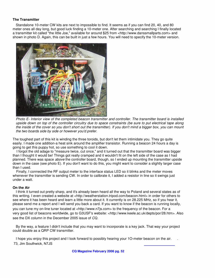
Photo E- Interior view of the completed beacon transmitter and controller. The transmitter board is installed upside down on top of the controller circuitry due to space constraints (be sure to put electrical tape along the inside of the cover so you don't short out the transmitter). If you don't mind a bigger box, you can mount the two boards side by side or however you'd prefer.
The toughest part of this kit is winding the three toroids, but don't let them intimidate you. They go quite easily. I made one addition-a heat sink around the amplifier transistor. Running a beacon 24 hours a day is going to get this puppy hot, so use something to cool it down.
I forgot the old adage to "measure twice, cut once," and it turned out that the transmitter board was bigger than I thought it would be! Things got really cramped and it wouldn't fit on the left side of the case as I had planned. There was space above the controller board, though, so I ended up mounting the transmitter upside down in the case (see photo E). If you don't want to do this, you might want to consider a slightly larger case than I used.
Finally, I connected the RF output meter to the interface status LED so it blinks and the meter moves whenever the transmitter is sending CW. In order to calibrate it, I added a resistor in line so it swings just under a watt.
On the Air
I think it turned out pretty sharp, and it's already been heard all the way to Poland and several states as of this writing. I even created a website at <http://weatherstation.tripod.com/beacon.html> in order for others to see where it has been heard and learn a little more about it. It currently is on 28.225 MHz, so if you hear it, please send me a report and I will send you back a card. If you want to know if the beacon is running locally,
you can tune my on-line tuner located at <http://www.n7js.com> to the frequency of the beacon. For a
very good list of beacons worldwide, go to G3USF's website: <http://www.keele.ac.uk/depts/por/28.htm>. Also
see the DX column in the December 2005 issue of CQ.
By the way, a feature I didn't include that you may want to incorporate is a key jack. That way your project
could double as a QRP CW transmitter.
I hope you enjoy this project and I look forward to possibly hearing your 1O-meter beacon on the air. .
73, Jim Southwick, N7JS
CQ Magazine February 2006 pg. 52


