BE Lesson 4: Transistors What are semi-conductor transistors? What’s the primary difference...
19
BE Lesson 4: Transistors • What are semi-conductor transistors? • What’s the primary difference between a bipolar transistor and unijunction transistor? • How we can use these transistors. © 2012 C. Rightmyer, Licensed under The MIT OSI License, 20 July 2012
-
Upload
madeleine-carter -
Category
Documents
-
view
235 -
download
0
Transcript of BE Lesson 4: Transistors What are semi-conductor transistors? What’s the primary difference...

BE Lesson 4: Transistors
• What are semi-conductor transistors?
• What’s the primary difference between a bipolar transistor and unijunction transistor?
• How we can use these transistors.
© 2012 C. Rightmyer, Licensed under The MIT OSI License, 20 July 2012
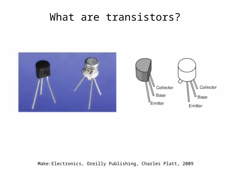
What are transistors?
Make:Electronics, Oreilly Publishing, Charles Platt, 2009

Silicon based semiconductor doping
Silicon atom with 4 electrons in outer shell
Silicon atoms sharing outer electrons
Hole
Extra electron
Silicon crystal with Boron atom
Silicon crystal with Phosphorus atom
Adapted from Getting Started in Electronics, Master Publishing, Inc., Forrest M. Mims III, 2010

How an NPN type transistor works
Practical Electronics for Inventors, McGraw Hill, Paul Scherz, 2007

Symbols and example math for bipolar transistors
NPN PNP

BE ckt 4-1. Illustrating current amplification using an NPN bipolar transistor (2N3904).
+
volts
LED
100
4.7K
LED
2N3904B
C
E
Adapted from Electronic Kourseware Interactive, Discover Electronics, A8, www.eki.com

BE ckt 4-1. Hook up diagram.
+
9.0
volts
1004.7K
LED
2N 3904(face points towards
bottom of breadboard)
LEDce
b
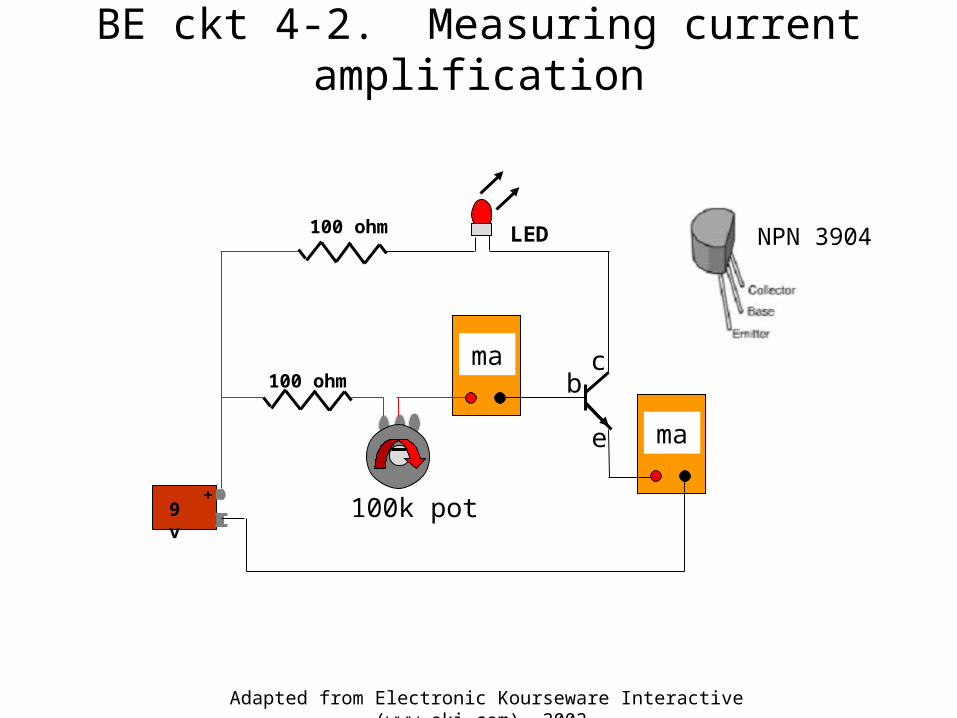
BE ckt 4-2. Measuring current amplification
Adapted from Electronic Kourseware Interactive (www.eki.com), 2002
LED100 ohm
100k pot9 v
+
ma
ma
c
e
b
NPN 3904
100 ohm

BE ckt 4-2. Hookup diagram.
+
9.0
volts10
0
100
NPN 3904(faces down on breadboard)
LED ce
b100k pot
ma
ma

A Programable Unijunction Transistor (PUT)

BE ckt 4-3. A flashing LED circuit using a 2N6017 Programmable Unijunction Transistor (PUT)
BE ckt 4-3
Adapted from Make:Electronics, Oreilly Publishing, Charles Platt, 2009
82k 10 uf
10k 20k
R1
R2 R3
C1
LED
9VDC

BE ckt 4-3. Hookup diagram
+
10 uf
ca82K
g
220
LED
10K
20K
a = anode c = cathode g = gate
Note: Transistor 2N6027 faces down on the breadboard)
+
9.0
volts

BE ckt 4-4. The “Blinking” Project

Front of protoboard (ckt 4-4a)
82k = Gray-Red-Orange 10k = Brown-Black-Orange
20k = Red-Black-Orange 220 = Red-Red-Black
10
k
20
k
This symbol means you are to twist one of the bareWire leads around the otherup close to the bottom ofthe board.Two turns is enough.

Front of protoboard (ckt 4-4b)
82k = Gray-Red-Orange 10k = Brown-Black-Orange
20k = Red-Black-Orange 220 = Red-Red-Black
10
k
82 k
20
k

Front of protoboard (ckt 4-4c)
82k = Gray-Red-Orange 10k = Brown-Black-Orange
20k = Red-Black-Orange 220 = Red-Red-Black
10
k
82 k
20
k

Front of protoboard (ckt 4-4d)
82k = Gray-Red-Orange 10k = Brown-Black-Orange
20k = Red-Black-Orange 220 = Red-Red-Black
10
k
82 k
220
20
k
10 uF+1
0
k
82 k
220
20
k

Front of protoboard (ckt 4-4e)
82k = Gray-Red-Orange 10k = Black-Black-Orange
20k = Red-Black-Orange 220 = Red-Red-Black
10
k
82 k
220
20
k
10 f
+

Completed ckt 4-4
82k = Gray-Red-Orange 10k = Black-Black-Orange
20k = Red-Black-Orange 220 = Red-Red-Black
10
k
82 k
220
20
k
10 f
+