BDS at reduced beam parameters 2nd Baseline Assessment Workshop on Reduced Beam Parameter set Andrei...
32
BDS at reduced beam parameters 2nd Baseline Assessment Workshop on Reduced Beam Parameter set Andrei Seryi John Adams Institute 19 January 2011
-
Upload
silvester-allen -
Category
Documents
-
view
224 -
download
0
Transcript of BDS at reduced beam parameters 2nd Baseline Assessment Workshop on Reduced Beam Parameter set Andrei...
BDS at reduced beam parameters
2nd Baseline Assessment Workshop on Reduced Beam Parameter set
Andrei SeryiJohn Adams Institute
19 January 2011

Outline
• Layout and optics• Parameters and luminosity in details• FD updates • Simulation of TF generation by transverse cavity
– Separate presentation (N.W.)
• Wang-Gao-Kubo parameters
A. Seryi, 19 Jan 2011, BAW Global Design Effort 2

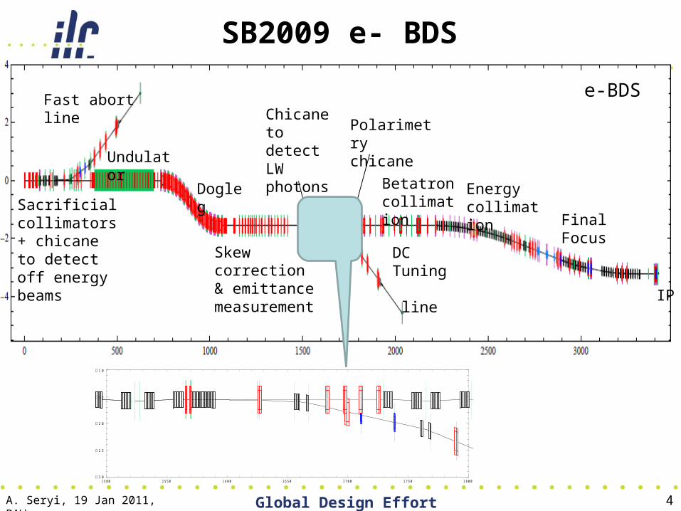
e-BDS
Sacrificial collimators + chicane to detect off energy beams
Fast abort line
Undulator
Dogleg
Skew correction & emittance measurement
Chicane to detect LW photons
DC Tuning line
Polarimetry chicane
Betatron collimation
Energy collimation
Final Focus
IP
SB2009 e- BDS
Changes on e- side due to central integration : dogleg design & tolerances
Separated polarimeter chicane from RDR combined functionalities.
D. Angal-Kalinin et alhttp://projects.astec.ac.uk/ilcdecks/ A. Seryi, 19 Jan 2011, BAW
A. Seryi, 19 Jan 2011, BAW Global Design Effort 4
e-BDS
Sacrificial collimators + chicane to detect off energy beams
Fast abort line
Undulator
Dogleg
Skew correction & emittance measurement
Chicane to detect LW photons
DC Tuning line
Polarimetry chicane
Betatron collimation
Energy collimation
Final Focus
IP
15 00 15 50 16 00 16 50 17 00 17 50 18 00 3 .0
2 .5
2 .0
1 .5
1 .0
SB2009 e- BDS

A. Seryi, 19 Jan 2011, BAW Global Design Effort 5
SB2009 e- BDS Optics
A. Seryi, 19 Jan 2011, BAW Global Design Effort 6
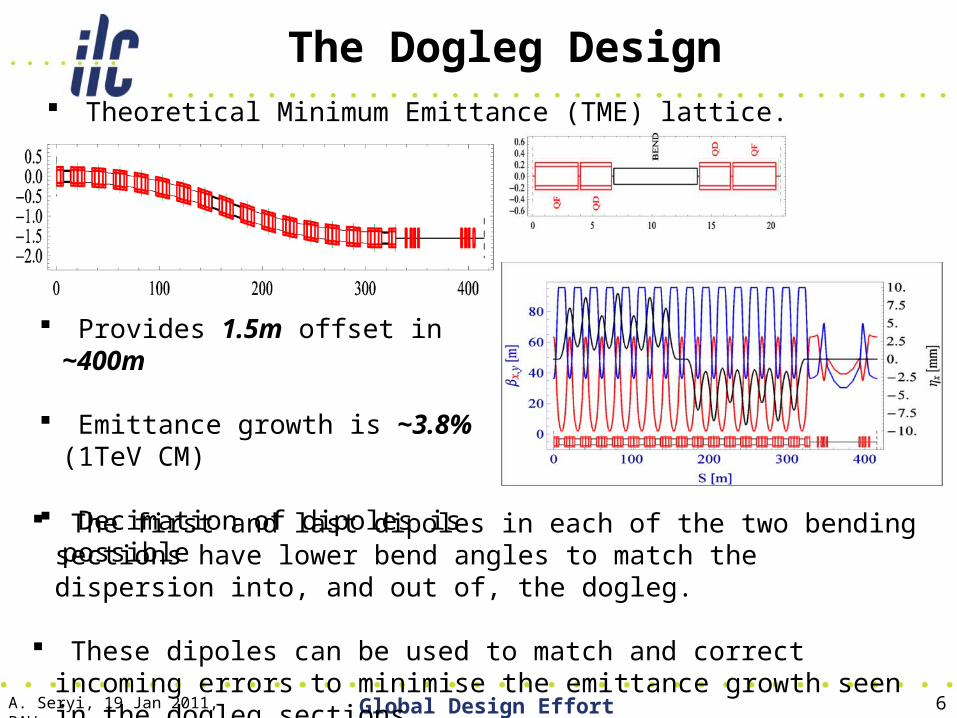
Theoretical Minimum Emittance (TME) lattice.
The Dogleg Design
Provides 1.5m offset in ~400m
Emittance growth is ~3.8% (1TeV CM)
Decimation of dipoles is possible The first and last dipoles in each of the two bending sections have lower
bend angles to match the dispersion into, and out of, the dogleg.
These dipoles can be used to match and correct incoming errors to minimise the emittance growth seen in the dogleg sections.
A. Seryi, 19 Jan 2011, BAW Global Design Effort 7
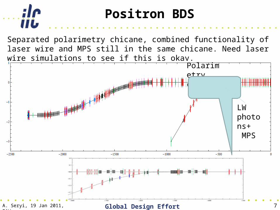
Separated polarimetry chicane, combined functionality of laser wire and MPS still in the same chicane. Need laser wire simulations to see if this is okay.
LW photons+ MPS
Polarimetry chicane
Positron BDS
A. Seryi, 19 Jan 2011, BAW Global Design Effort 8
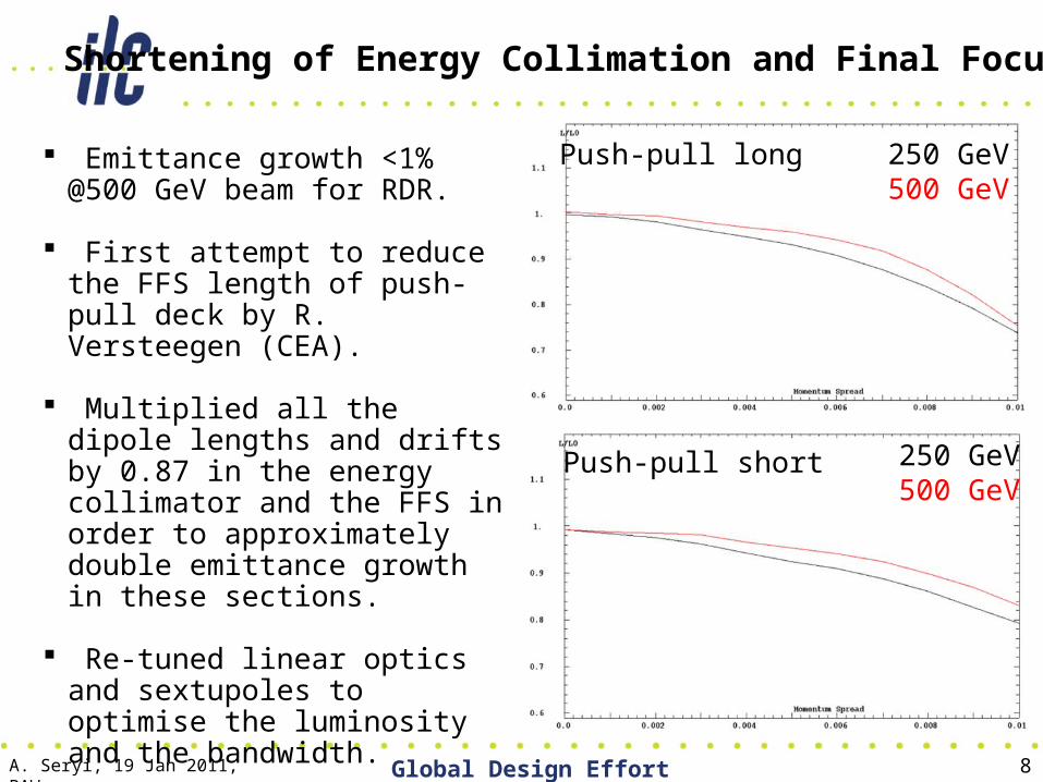
Shortening of Energy Collimation and Final Focus
Emittance growth <1% @500 GeV beam for RDR.
First attempt to reduce the FFS length of push-pull deck by R. Versteegen (CEA).
Multiplied all the dipole lengths
and drifts by 0.87 in the energy collimator and the FFS in order to approximately double emittance growth in these sections.
Re-tuned linear optics and sextupoles to optimise the luminosity and the bandwidth.
250 GeV500 GeV
250 GeV500 GeV
Push-pull long
Push-pull short
A. Seryi, 19 Jan 2011, BAW Global Design Effort 9
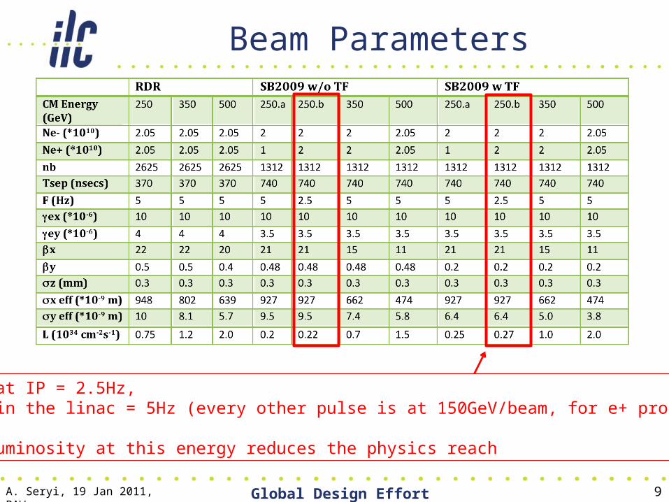
Beam Parameters
Rate at IP = 2.5Hz, Rate in the linac = 5Hz (every other pulse is at 150GeV/beam, for e+ production)
Low luminosity at this energy reduces the physics reach
A. Seryi, 19 Jan 2011, BAW Global Design Effort 10
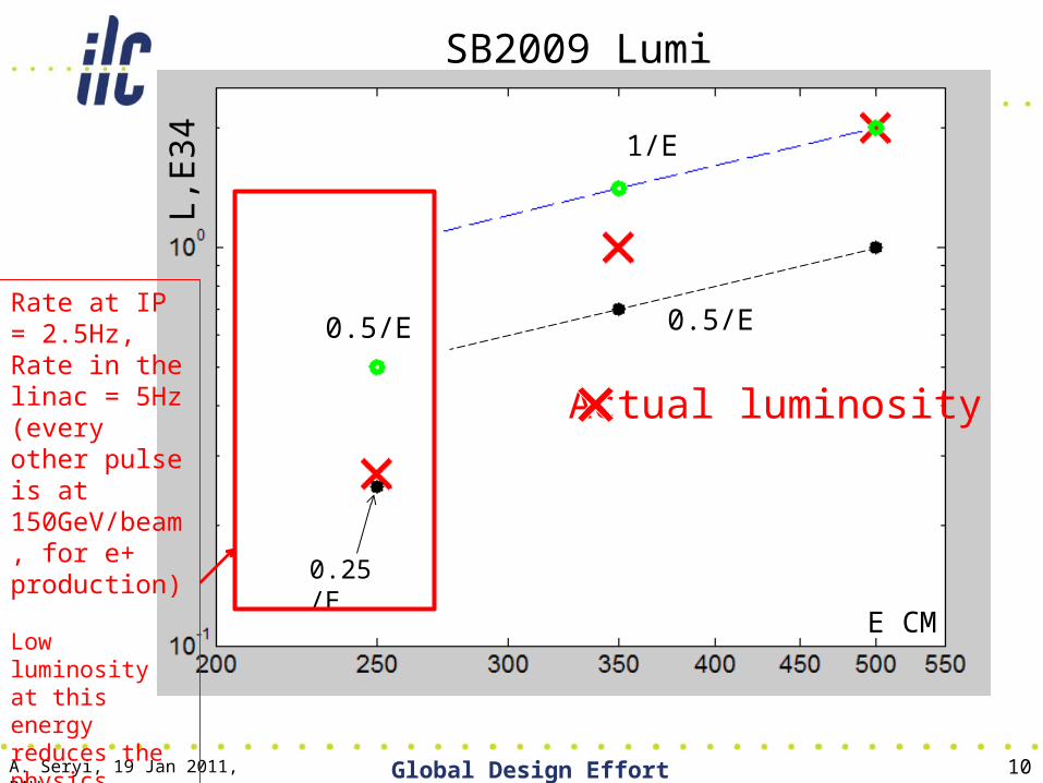
L,E
34
E CM
1/E
0.5/E
0.25/E
0.5/E
SB2009 Lumi
Actual luminosity
Rate at IP = 2.5Hz, Rate in the linac = 5Hz (every other pulse is at 150GeV/beam, for e+ production)
Low luminosity at this energy reduces the physics reach
A. Seryi, 19 Jan 2011, BAW Global Design Effort 11
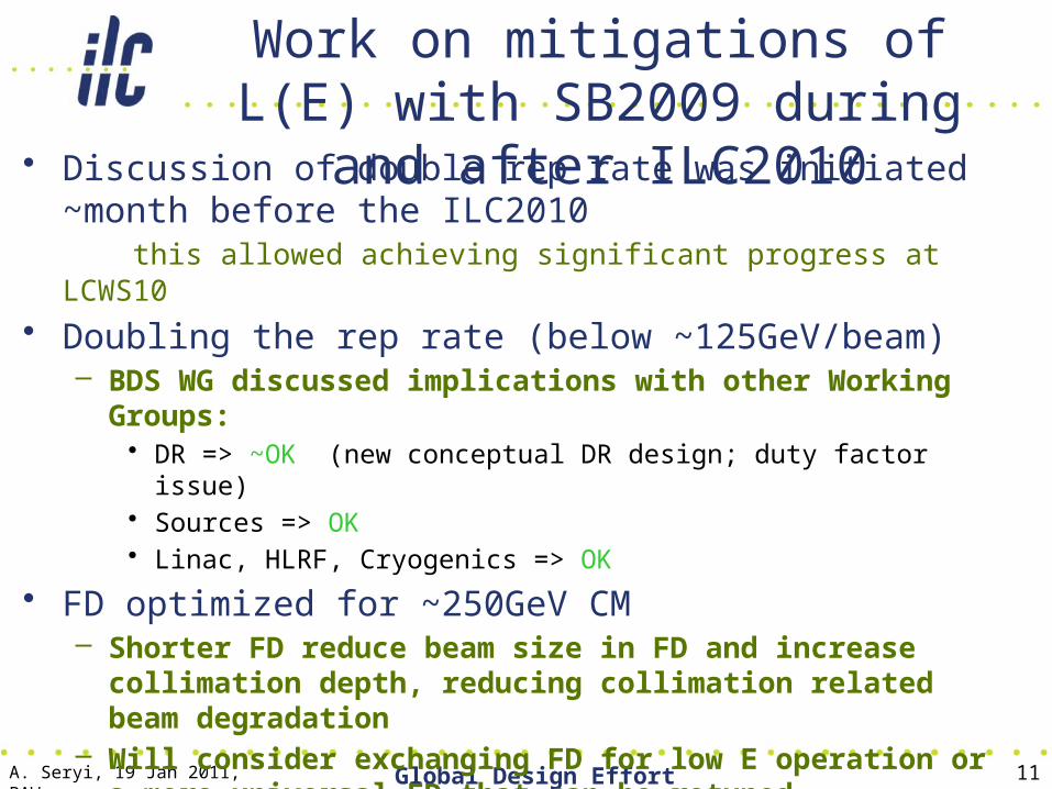
Work on mitigations of L(E) with SB2009 during and after ILC2010
• Discussion of double rep rate was initiated ~month before the ILC2010
this allowed achieving significant progress at LCWS10
• Doubling the rep rate (below ~125GeV/beam)– BDS WG discussed implications with other Working Groups:
• DR => ~OK (new conceptual DR design; duty factor issue)• Sources => OK• Linac, HLRF, Cryogenics => OK
• FD optimized for ~250GeV CM– Shorter FD reduce beam size in FD and increase collimation
depth, reducing collimation related beam degradation – Will consider exchanging FD for low E operation or a more
universal FD that can be retuned

A. Seryi, 19 Jan 2011, BAW Global Design Effort 12
Lumi(E) dependence in SB2009
• Factor determine shape of L(E) in SB2009– Lower rep ( /2) rate below ~125GeV/beam– Collimation effects: increased beam degradation at
lower E due to collimation wakes and due to limit (in X) on collimation depth
• Understanding the above limitations, one can suggest mitigation solutions:– 1) Consider doubling the rep rate at lower energy– 2) Consider Final Doublet optimized for 250GeV CM
A. Seryi, 19 Jan 2011, BAW Global Design Effort 13
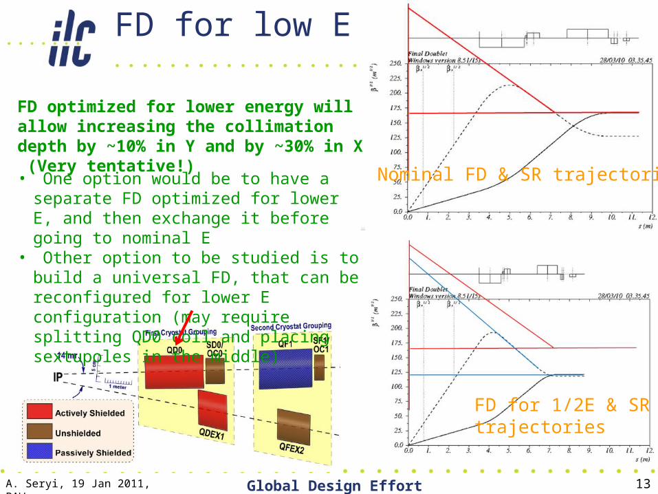
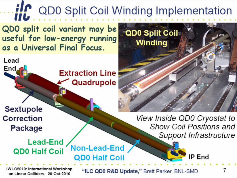
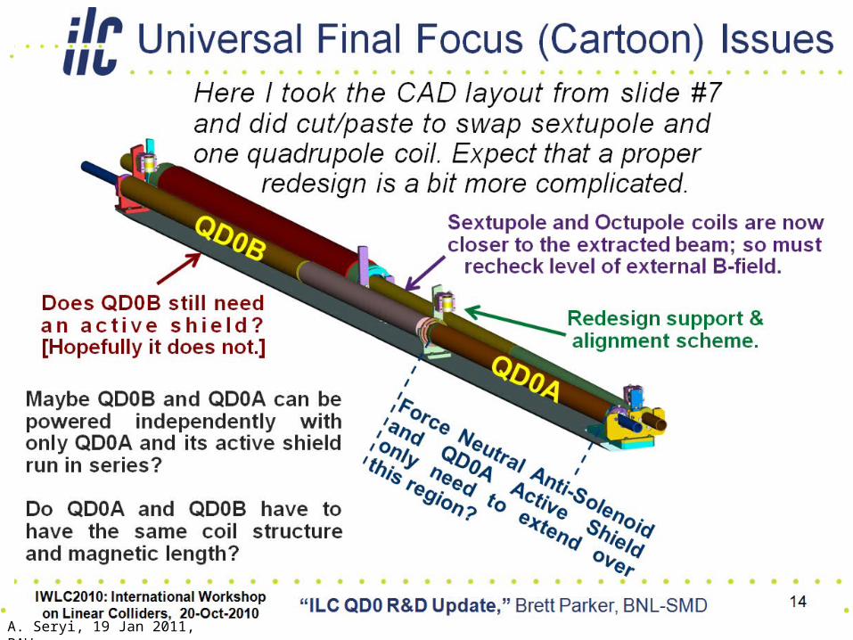
• One option would be to have a separate FD optimized for lower E, and then exchange it before going to nominal E
• Other option to be studied is to build a universal FD, that can be reconfigured for lower E configuration (may require splitting QD0 coil and placing sextupoles in the middle)
FD optimized for lower energy will allow increasing the collimation depth by ~10% in Y and by ~30% in X (Very tentative!)
FD for low E
Nominal FD & SR trajectories
FD for 1/2E & SRtrajectories
A. Seryi, 19 Jan 2011, BAW Global Design Effort 14
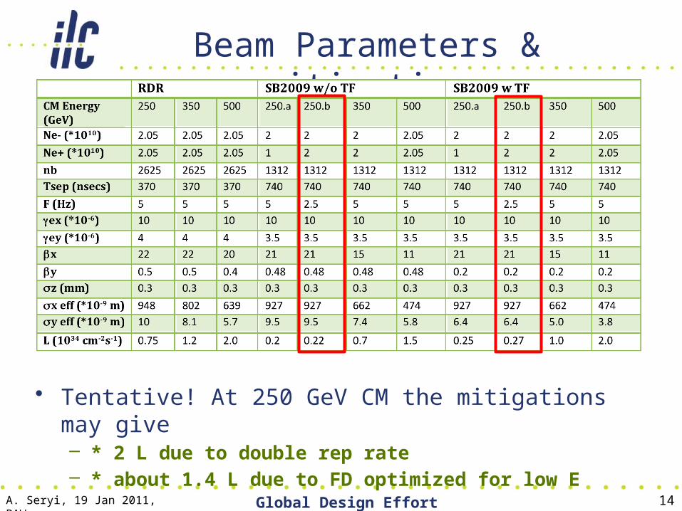
Beam Parameters & mitigation
• Tentative! At 250 GeV CM the mitigations may give– * 2 L due to double rep rate– * about 1.4 L due to FD optimized for low E
A. Seryi, 19 Jan 2011, BAW Global Design Effort 15
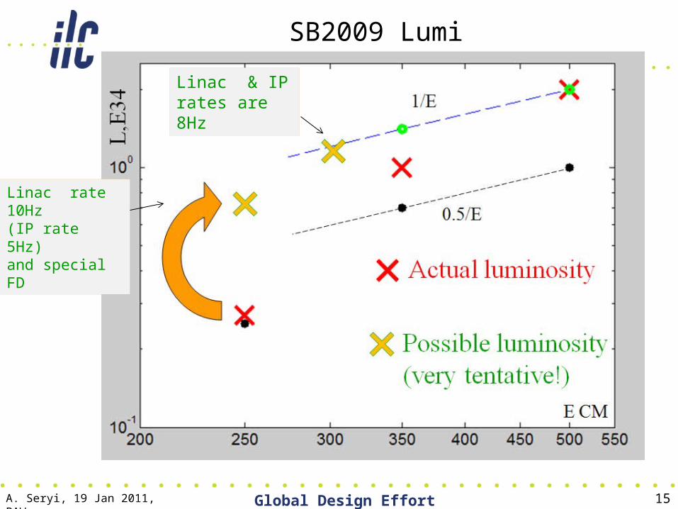
SB2009 Lumi
Linac rate 10Hz(IP rate 5Hz) and special FD
Linac & IP rates are 8Hz

New parameters based on the following assumptions
• Starting point: parameters developed by the Physics Questions Committee (B. Foster, A. Seryi, J. Clarke, M. Harrison, D. Schulte, T. Tauchi) in December 2009.
• Take into account progress on 10Hz rep rate for low E achieved after LCWS10• There are issues with DR duty cycle that are being studied, however assume that they will be solved
• Assume that we will develop and use new universal FD that gives additional luminosity improvement (only) for 200 and 250 GeV energies
• Consider the following energies: 200, 250, 350, 500 GeV CM• Assume single stage bunch compressor (min sigma_z=230um – will use
300um and consider 230 as an overhead or safety margin) • Assume 10Hz and 1300 bunches • Consider separately the cases with and without Travelling Focus• Energy and rep rate:
• E= 200 250 350 500 GeV CM• IP rep rate 5 5 5 5 Hz• Linac rate 10 10 5 5 Hz
( double pulsing )
A. Seryi, 19 Jan 2011, BAW Global Design Effort 16
A. Seryi, 19 Jan 2011, BAW Global Design Effort 17
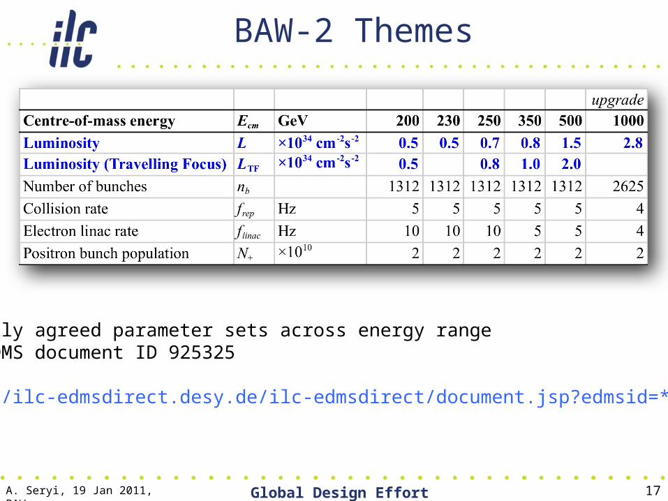
BAW-2 Themes
Formally agreed parameter sets across energy rangeILC-EDMS document ID 925325
http://ilc-edmsdirect.desy.de/ilc-edmsdirect/document.jsp?edmsid=*925325
A. Seryi, 19 Jan 2011, BAW Global Design Effort 18

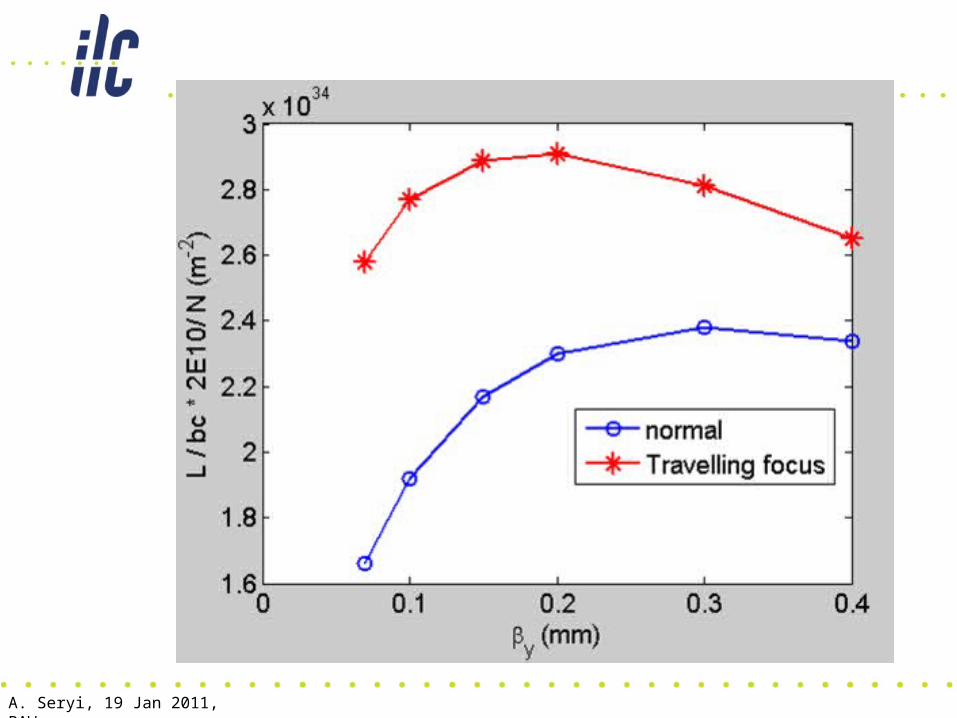
Arrows show location offocal point for each bunch at a particular moment
A. Seryi, 19 Jan 2011, BAW
A. Seryi, 19 Jan 2011, BAW
A. Seryi, 19 Jan 2011, BAW Global Design Effort 21
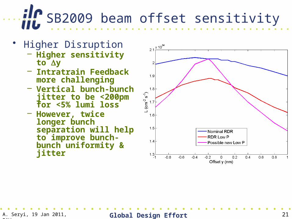
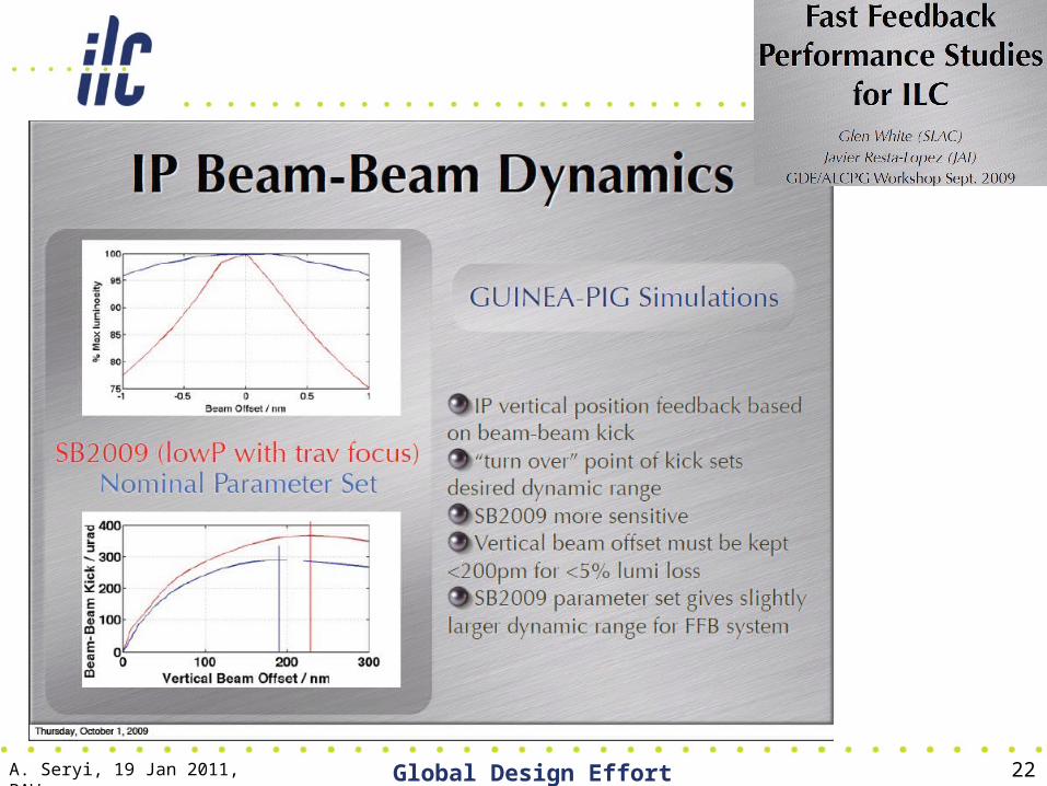
SB2009 beam offset sensitivity
• Higher Disruption– Higher sensitivity to Dy– Intratrain Feedback more
challenging– Vertical bunch-bunch
jitter to be <200pm for <5% lumi loss
– However, twice longer bunch separation will help to improve bunch-bunch uniformity & jitter
A. Seryi, 19 Jan 2011, BAW Global Design Effort 22
• The travelling focus can be created in two ways. • The first way is to have small uncompensated
chromaticity and coherent E-z energy shift dE/dz along the bunch. One has to satisfy dE k L*
eff = sz
where k is the relative uncompensated chromaticity. The dE needs to be 2-3 times the incoherent spread in the bunch. Thus, the following set may be used: dE=0.3%, k=1.5%, L*
eff =6m.
• It is clear that additional energy spread affect the physics. Therefore, second method is considered:
A. Seryi, 19 Jan 2011, BAW

• The second way to create a travelling focus is to use a transverse deflecting cavity giving a z-x correlation in one of the FF sextupoles and thus a z-correlated focusing
• The cavity would be located about 100m upstream of the final doublet, at the p/2 betatron phase from the FD
• The needed strength of the travelling focus cavity can be compared to the strength of the normal crab cavity (which is located just upstream of the FD): – Utrav.cav./Ucrab.cav. = hFD R12
cc/ (L*eff qc R12
trav). – Here hFD is dispersion in the FD, qc full crossing angle, R12
trav and R12
cc are transfer matrix elements from travelling focus transverse cavity to FD, and from the crab cavity to IP correspondingly.
• For typical parameters hFD =0.15m, qc =14mrad. R12cc =10m,
R12trav =100m, L*
eff =6m one can conclude that the needed strength of the travelling focus transverse cavity is about 20% of the nominal crab cavity.
A. Seryi, 19 Jan 2011, BAW

QD0 R&D Prototype Coil Winding Status
A. Seryi, 19 Jan 2011, BAW
“Report to ATF2 Technical Board,”Brett Parker, BNL-SMD 26
• To control coil support tube position during winding, we split QD0 coil in order to have a fixed support.
• Coil winding of all the quadrupole layers is complete and the measured harmonic agree with expectations.
• Vertical cold test has been done; tested to 10% above operating current without quenching; forced quenches with spot heater, saw no degradation.
• Have started winding octupole coil correction windings; next we will start winding the main sextupole coil sets.
QD0 coil production
Octupole coil test winding
A. Seryi, 19 Jan 2011, BAW
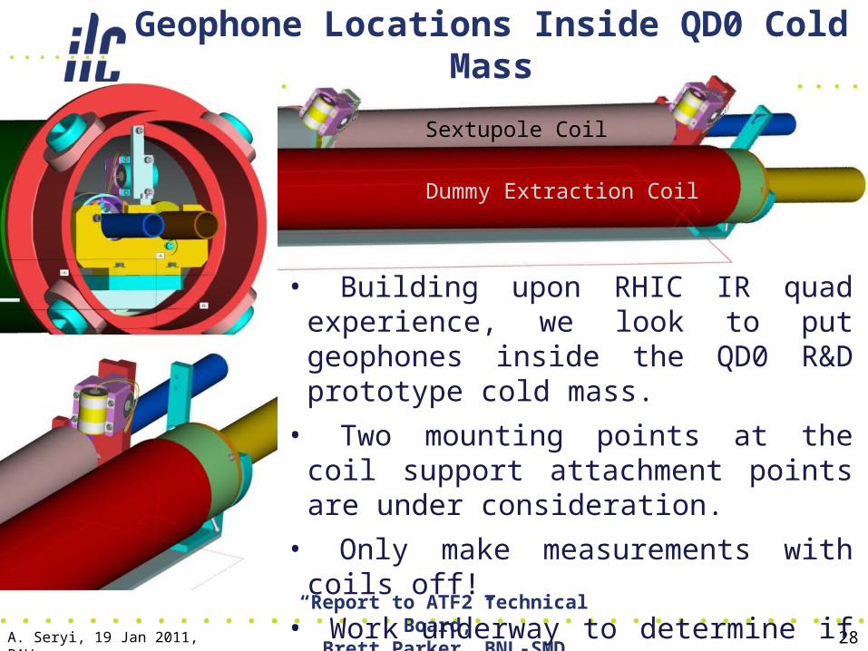
Geophone Locations Inside QD0 Cold Mass
A. Seryi, 19 Jan 2011, BAW
“Report to ATF2 Technical Board,”Brett Parker, BNL-SMD
28
• Building upon RHIC IR quad experience, we look to put geophones inside the QD0 R&D prototype cold mass.
• Two mounting points at the coil support attachment points are under consideration.
• Only make measurements with coils off!
• Work underway to determine if fringe fields from coils might still damage sensors.
Sextupole Coil
Dummy Extraction Coil

QD0 Field Stability Direct Measurement
A. Seryi, 19 Jan 2011, BAW
“Report to ATF2 Technical Board,”Brett Parker, BNL-SMD
29
• Develop thin walled, warm finger design with test coil stabilized independent of QD0 structure.
• Multi-turn probe coil would be mounted in fixture that could be rotated 90º to measure changes in either the horizontal or vertical field.
• It is critical to carefully adjust coil centering so as to minimize sensitivity to power supply ripple.
• Do this adjustment via deliberate AC current excitation of the magnet coils.
• Need to determine if “I-Beams” on either side of coil holder have to be non-conducting (or SS).
20 mm
20 mm

A. Seryi, 19 Jan 2011, BAW Global Design Effort 30
Nominal RDR SB2009 RDR Low charge New low charge
Ecm (GeV) 500 500 500 500
Ne 2×10¹⁰ 2×10¹⁰ 1.0×10¹⁰ 1.0×10¹⁰
Frep (Hz) 5 5 5 5
Nb 2625 1320 5640 2625
Pb (MW) 10.5 5.3 11.3 5.37
x (mm) 20 11 12 8
y (m) 400 200 200 166
x (m) 10 10 10 10
y (nm) 40 36 30 10
x (nm) 639 474 495 404
y (nm) 5.7 3.8 3.5 2.0
z (m) 300 300 150 166
B 0.031 0.056 0.026 0.0241
n 1.3 1.74 0.832 1.01
Dy 19.0 38.4 10.0 24.0
HD 1.74 1.63? 1.56 1.6
(rad) 0.00036 0.00048 0.00023 0.00029
Nhad 1.1 3.6 0.21 0.66
Trav. focus No Yes No Yes
L0 (cm-2s-1) 2.0×1034 1.9×1034 2.0×1034 2.0×1034
Beam parametersDou Wang (IHEP), Jie Gao (IHEP), K. Kubo (KEK)
New low charge (GP):
L=1.75E34 w/o TF,
L=2.0E34with TF

Wang-Gao-Kubo parameters
• The luminosity gets to 2E34 with travelling focus• Some of the nasty beam-beam effects and
sensitivities are eased • The additional issues with this set is stronger
focusing and tighter collimation depth and large wakes effect of the beam
• The need of 2 stage bunch compressor• Cannot comment on cost saving• Worth to have a look at this alternative set
A. Seryi, 19 Jan 2011, BAW Global Design Effort 31
Conclusion
• The RDR (2007) focused on nominal energy• Parameter set that maintains the physics
reach and optimizes the cost/performance has been developed – SB2009
• Future studies– Detailed design of the universal final doublet– Optimization of collimation depth– Study of FF tuning with needed beta*– Detailed beam-beam studies – Damping ring design– …
A. Seryi, 19 Jan 2011, BAW Global Design Effort 32