BDA MX6 EN 20130628 - s514780755.website-start.de
44
USER INSTRUCTIONS .......................... 38 Please read the manual before using the equipment! MX6
Transcript of BDA MX6 EN 20130628 - s514780755.website-start.de

USER INSTRUCTIONS .......................... 38 Please read the manual before using the equipment!
MX6
36 MX6
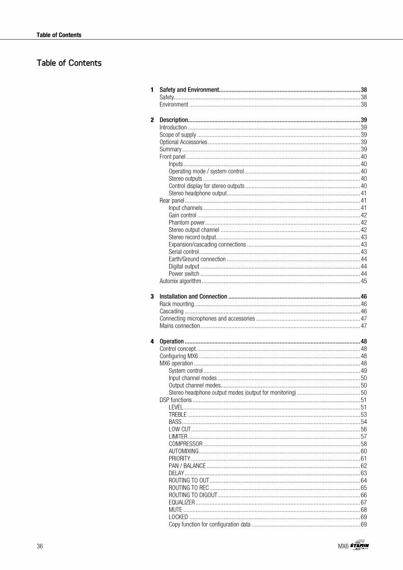
Table of Contents
1 Safety and Environment........................................................................................... 38
Safety ........................................................................................................................ 38
Environment .............................................................................................................. 38
2 Description ............................................................................................................... 39
Introduction ............................................................................................................... 39
Scope of supply ......................................................................................................... 39
Optional Accessories .................................................................................................. 39
Summary ................................................................................................................... 39
Front panel ................................................................................................................ 40
Inputs .................................................................................................................. 40
Operating mode / system control ........................................................................... 40
Stereo outputs ..................................................................................................... 40
Control display for stereo outputs .......................................................................... 40
Stereo headphone output ...................................................................................... 41
Rear panel ................................................................................................................. 41
Input channels ..................................................................................................... 41
Gain control ......................................................................................................... 42
Phantom power .................................................................................................... 42
Stereo output channel .......................................................................................... 42
Stereo record output ............................................................................................. 43
Expansion/cascading connections ......................................................................... 43
Serial control ........................................................................................................ 43
Earth/Ground connection ...................................................................................... 44
Digital output ....................................................................................................... 44
Power switch ....................................................................................................... 44
Automix algorithm ...................................................................................................... 45
3 Installation and Connection ..................................................................................... 46
Rack mounting ........................................................................................................... 46
Cascading ................................................................................................................. 46
Connecting microphones and accessories ................................................................... 47
Mains connection ....................................................................................................... 47
4 Operation ................................................................................................................. 48
Control concept .......................................................................................................... 48
Configuring MX6 ........................................................................................................ 48
MX6 operation ........................................................................................................... 48
System control ..................................................................................................... 49
Input channel modes ............................................................................................ 50
Output channel modes.......................................................................................... 50
Stereo headphone output modes (output for monitoring) ......................................... 50
DSP functions ............................................................................................................ 51
LEVEL .................................................................................................................. 51
TREBLE ............................................................................................................... 53
BASS ................................................................................................................... 54
LOW CUT ............................................................................................................. 56
LIMITER ............................................................................................................... 57
COMPRESSOR ..................................................................................................... 58
AUTOMIXING ........................................................................................................ 60
PRIORITY ............................................................................................................. 61
PAN / BALANCE ................................................................................................... 62
DELAY ................................................................................................................. 63
ROUTING TO OUT ................................................................................................. 64
ROUTING TO REC ................................................................................................. 65
ROUTING TO DIGOUT ............................................................................................ 66
EQUALIZER .......................................................................................................... 67
MUTE .................................................................................................................. 68
LOCKED .............................................................................................................. 69
Copy function for configuration data ...................................................................... 69
Table of Contents

MX6 37
Table of Contents
Resetting the factory settings ................................................................................ 71
5 Cleaning ................................................................................................................... 72
6 Specifications .......................................................................................................... 73
General ..................................................................................................................... 73
Power supply unit ....................................................................................................... 73
Inputs ........................................................................................................................ 73
Outputs ..................................................................................................................... 73
7 Troubleshooting ....................................................................................................... 74
8 Notizen - Notes ........................................................................................................ 75
9 Notizen - Notes ........................................................................................................ 76
FCC statement
This equipment has been tested and found to comply with the limits for a Class B digital device, pursuant to Part 15 of the FCC Rules. These limits are designed to provide reasonable protection against harmful interference in a residential installation. This equipment generates, uses, and can radiate radio frequency energy and, if not installed and used in accordance with the instructions, may cause harmful interference to radio communications. However, there is no guarantee that interference will not occur in a particular installation. If this equipment does cause harmful interference to radio or television reception, which can be determined by turning the equipment off and on, the user is encouraged to try to correct the interference by one or more of the following measures:
• Reorient or relocate the receiving antenna.
• Increase the separation between the equipment and the receiver.
• Connect the equipment to an outlet on a circuit different from that to which the receiver is connected.
• Consult the dealer or an experienced radio/TV technician for help. Shielded cables and I/O cords must be used for this equipment to comply with the relevant FCC regulations. Changes or modifications not expressly approved in writing by STEMIN GMBH may void the user’s authority to operate this equipment. This device complies with Part 15 of the FCC Rules. Operation is subject to the following two conditions: (1) this device may not cause harmful interference, and (2) this device must accept any interference received, including interference that may cause undesired operation.

38 MX6
Safety and Environment
• Do not expose the unit to direct sunlight, excessive dust or moisture, rain, vibrations or shocks.
• Do not spill any liquids on the unit or drop any objects through the vents into the unit.
• The unit may be used in dry rooms only.
• The unit may be opened, serviced and repaired by authorised personnel only. The unit contains no user-serviceable parts.
• Before starting up the unit, check that the operating voltage indicated on the unit is the same as the mains voltage where you will be using the unit.
• Only operate the unit with a mains voltage of between 90 and 240 V AC. Other types of current and voltages may cause serious damage to the unit!
• Immediately disconnect the unit if a solid object or liquid enters the interior of the unit. In this case, immediately disconnect the power cord of the power supply unit from the socket and have the unit checked by our customer service personnel.
• Do not place the unit close to heat sources such as radiators, heating ducts or amplifiers, etc. and do not expose it to direct sunlight, excessive dust or moisture, rain, vibrations or shocks.
• To avoid interference, position all cables, in particular those of the microphone inputs, away from power lines. If cables are to be installed in channels or cable ducts, be sure to place the transmission lines in a separate duct.
• Clean the unit with a moistened (not wet) cloth only. Before doing so, it is essential to unplug the unit's power cord from the socket! Never use caustic or scouring cleaners or cleaning agents containing alcohol or solvents, since these may damage the enamel and plastic parts.
• Use the unit only for the purposes described in these operating instructions. STEMIN GMBH will accept no liability for damage caused by incorrect handling or improper use.
• When the product reaches the end of its life, separate the housing, electronics and cables and dispose of all components in accordance with local waste disposal regulations.
• The packaging can be recycled. Dispose of the packaging in a suitable collection system.
1 Safety and Environment
Safety
Environment

MX6 39
Description
Thank you for purchasing an STEMIN GMBH product. This Manual contains important instructions for setting up and operating your equipment. Please take a few minutes to read the instructions below carefully before operating the equipment. Please keep the Manual for future reference. Have fun and impress your audience!
Please check that the packaging contains all the components. If anything is missing, please contact your STEMIN GMBH dealer.
• 1 x MX6
• 1 x Quick Setup Guide
For optional accessories, refer to the current STEMIN GMBH catalog or folder, or visit www.Stemin.com. Your dealer will be glad to help.
The MX6 is a 19" automatic microphone mixer. Internal signal processing takes place digitally and on three master buses (stereo). The mixer has analogue inputs and outputs.
It also has six balanced inputs, which can be configured as microphone inputs or line inputs (e.g. for wireless microphone receivers).
On the output side it has one stereo master output channel, a stereo recording output and a stereo headphone output.
Inputs and outputs are controlled by the rotary knobs and circular LED displays on the front panel. The device has a wide-range power supply unit and is connected to the mains using the mains cable supplied.
In addition to many digital signal processing functions, the MX6 also has innovative automatic mixing functions.
Up to ten MX6 can be cascaded if the six balanced inputs are not sufficient for your application.
2 Description
Introduction
Scope of supply
Optional Accessories
Summary

40 MX6
Description
There are nine rotary knobs on the front panel.
Figure 1: Front of MX6
1 to 6: Microphone or line inputs 7: Operating mode / system control 8: Stereo output 9: Control display for stereo outputs 10: Stereo headphone output 11: Headphone connection
The rotary knobs can be used to adjust the parameters of the selected audio function.
Each input channel has a green "ON" LED and a red "PEAK" LED. "ON" lights up when the input channel is connected. "ON" remains illuminated if the automix function is switched off. "PEAK" lights up when the signal on an input channel is close to the maximum control limit. In this case, the level should be turned down or the input sensitivity should be changed.
NOTE
Due to the clarity, the active blue LED's of the knob of the auto mixer in the owner's manual instructions are shown in yellow color.
NOTE
The input sensitivity is adjusted using the gain control on the rear panel of the connected unit.
NOTE
MUTE function: Briefly pressing a rotary knob causes the corresponding channel to be muted. The MUTE function is indicated by the steady flashing of the LED rings. Another brief press of the rotary knob removes the MUTE function. VU function: The "SYSTEM CONTROL" rotary knob can be used to display the current audio level of the inputs, see MX6 operation.
Inputs
The MX6 has six balanced input channels for connecting low-impedance dynamic or condenser microphones and other audio sources, e.g. receivers for wireless microphones. A rotary knob is available for each input channel. These are labelled "IN 1" to "IN 6".
Operating mode / system control
The MX6 has a large number of functions, such as volume, treble ranges, bass, auto-mix functions, etc. The "SYSTEM CONTROL" rotary knob can be used to select these functions.
Stereo outputs
The rotary knob for the stereo output channels is labelled "OUT". This rotary knob adjusts the volume, treble and bass range, limiting behaviour, balance and delay in the output channel.
Control display for stereo outputs
The control displays under the rotary knob for the stereo output channels indicate the output level in dB.
Front panel

MX6 41
Description
Stereo headphone output
Both the inputs and outputs can be monitored on the stereo headphone output. Hold down the "HEADPHONE" rotary knob and select another monitor source by pressing another rotary knob. You can monitor several sources with inputs. In mono, they are simultaneously switched to the left and right headphone channel. The output can only monitor individual sources, but in stereo. The previous monitoring source is switched off by pressing on another source (switch between inputs and output). The output "REC (OUT)" cannot be monitored.
Figure 2: Back of the MX6
1, 5, 6, 10, 11, 15: Input channels 2, 4, 7, 9, 12, 14: Gain control
3, 8, 13: Phantom power 16a: Stereo output channel, left 16b: Stereo output channel, right 17: Stereo record output 18: Expansion connectors 19: Serial control (RS232) 20: Phoenix terminal (grounding / remote control) 21: Mains switch 22: Mains connection 23: Digital Out
Input channels
Figure 3: Input channels
The six balanced input channels can be accessed via 3-pin XLR sockets. These are labelled "IN 1" to "IN 6". The input levels can be adjusted with the rotary knobs "IN 1" to "IN 6" on the front panel.
A switch for the phantom power and a gain control for every channel is located between two XLR sockets.
The assignment is identified by the "IN 3" socket with: "Pin 1 = _|_, Pin 2 = a, Pin 3 = b".
Rear panel

42 MX6
Description
Gain control
Figure 4: Gain control
The associated gain control is located next to every input channel, with integrated switch for the left stop, to set the input level. The input level is set at 0 dB when the left end stop is reached. By turning the control clockwise the gain can be increased by max. 57 dB.
Phantom power
Figure 5: PHANTOM POWER slide switch
The slide switches activate the phantom power supply of +48 V for the input channels located on the left or right. The slide switch is labelled with "PHANT. PWR". Two input channels are always activated simultaneously. The phantom power is activated when the slide switch is in the "On" position.
Stereo output channel
Figure 6: Stereo output channel
The device has a symmetrical stereo master output channel. It can be accessed via two 3 pin XLR sockets. The outputs are labelled with "OUT L" and "OUT R". The "OUT" rotary knob on the front is used to adjust the output level settings for the stereo output channel.

MX6 43
Description
Stereo record output
Figure 7: Recording output
Two RCA jacks, labelled "REC (OUT)", are available for connecting stereo recording equipment. The allocation of the individual channels to the asymmetrical stereo recording output can be configured as desired.
Expansion/cascading connections
Figure 8: EXPANSION
Two RJ-45 sockets are provided for expansion/cascading. These are labelled with "IN - EXPANSION - OUT".
Serial control
NOTE
This connection is for use by authorised specialist staff only!
Standard: RS-232
Use: connect to PC, firmware update, external control
Figure 9: RS232 socket
The serial control takes place using a 9 pin sub-D socket with the label "RS232". This socket allows you to perform software updates.
The pin assignment is as follows:
Pin Function 1 N.C. 2 RxD 3 TxD 4 N.C. 5 GND 6 GND 7 N.C. 8 N.C. 9 N.C.

44 MX6
Description
Earth/Ground connection
Figure 10: Phoenix terminal
A phoenix terminal connects the case with the 0 V potential of the power supply.
NOTE
Only bridge the 0 V potential with the grounding (factory setting) or connect it to the central system ground, as otherwise the phantom power has no reference point and will not function.
Analogue control
Figure 11: Phoenix terminal
A linear 50 kOhm potentiometer at the VCA input, labelled "VCA" and "⊥", allows you to vary the master volume.
Figure 12: VCA
The linear potentiometer is connected to the VCA input as shown above. The resistance at the VCA input is changed by turning the potentiometer. This value is input and the volume is changed accordingly. The left setting signifies 0% while the right setting signifies 100%.
The output level depends on the master control and the remote level control. The remote level control has the same affect on both masters.
Digital output
Figure 13: Digital output
The MX12 has a digital output which can be picked up via a balanced AES/EBU or an optical S/PDIF output on the rear panel of the device. The AES/EBU output can be accessed via a 3 pin Phoenix terminal. The assignment from left to right is a, b, shield. The optical output is accessible via a TOSLINK socket.
Both digital outputs have the same data signal. The signal is in stereo, has a 24 Bit data format and a sample frequency of 48 kHz.
The "ROUTING TO DIGOUT" function on the system control on the front panel can be used to individually or jointly route the inputs.
Power switch
The power switch is used to turn on the unit.

MX6 45
Description
The unit's automix algorithm has 3 basic functions which assess the amount by which an input signal is to be attenuated and the output signal's output level. The following functions and parameters flow into the automix algorithm:
Dynamic level adjustment
The master of all input channels is determined on an ongoing basis. This value is used as the reference value. If the input channel level is very close or over the reference value, this channel will be assessed as dominant and will be slightly attenuated. If the input channel level is well below the reference value, this is assessed as ambient noise and be severely attenuated. A channel's output level is calculated using the following formula:
Output level = Input level - (Reference value - Input level)
This formula ensures that the output level will not become louder if several input channels are active, rather the master assumes the level of a single channel. This reduces the risk of feedback. If a channel is no longer assessed as dominant, this falls at 1 dB/second and all other non-dominant channels increase with the same constant so that the master output level remains constant. The upward adjustment of a channel takes between 3 ms and 5 ms.
Best Mic On
With two microphones that are positioned close together there is the disadvantage that comb filter effects may arise by cancelling the frequency components. To suppress these unnaturally muffled or hollow signals, only the microphone channel with the highest level is assessed as dominant and switched on.
Noise Detect
Permanently present interfering signals, whose amplitude are large enough to be assessed as dominant, but whose level and frequency changes are too low, are not assessed as dominant. Interfering signals such as noise from fans and air-conditioning units are recognised and not used as activation criteria for microphone channels.
Automix algorithm

46 MX6
Installation and Connection
Mount the MX6 in your 19" rack.
NOTE
We recommend only using STEMIN GMBH accessory cables for cascading.
The unit has two 100 MBit/s ethernet interfaces. These communicate the control data and audio between up to 10 units. This allows an automix system with up to 60 input channels, 20 output channels and 10 stereo headphone outputs to be established.
The master buses for "OUT", "REC-OUT" and "HEADPHONE" are accessible for all of the cascaded units across the entire system. Every unit adds its input channels to the master buses, which are transferred via the ethernet interface. Every unit can monitor and output the master buses.
The automix algorithm also transfers its control data via this interface. This allows the automix algorithm to function system-wide.
The individual units must be connected to the expansion connectors as follows:
Figure 14: daisy-chaining multiple units
ATTENTION
Do not connect the first cascade unit with the last unit.
3 Installation and Connection
Rack mounting
Cascading

MX6 47
Installation and Connection
For the user, the function and behaviour of all the units are the same. All of the cascaded units retain their individual functions. A standard CAT5+ connection cable can be used.
The available "SYSTEM CONTROL" functions associated with cascading are described in the section Cascaded device operation.
NOTE
Before connecting, read the operating instructions for your microphones and accessories.
Connect microphones and accessories to the back of the MX6:
1) Connect microphones and other signal sources (e.g. wireless microphone receivers) to the "IN" input channels.
2) Connect the "OUT - L" and "OUT - R" output channels to a mixing desk or amplifier. 3) Connect the RCA jacks on the stereo recording output "REC (OUT)" to a recording device.
ATTENTION
Do not connect the unit to the mains power supply until you have established all the audio connections!
1) Connect the mains power supply cable to the appropriate socket on the rear panel of the MX6.
2) Plug the power supply cable into a mains socket.
Connecting microphones and accessories
Mains connection

48 MX6
Operation
There are nine rotary knobs on the front panel. These are labelled with "IN 1" to "IN 6", "SYSTEM CONTROL", "OUT" and "HEADPHONE".
The rotary knobs on the inputs are each surrounded by an LED ring with 15 yellow LEDs, one green LED and one red LED. The rotary knob "SYSTEM CONTROL" and the rotary knobs on the outputs are surrounded by 15 yellow LEDs. The control display under the outputs has 6 green, one yellow and one red LED.
The LED rings help to visualise the rotary knob setting or display signal levels.
NOTE
Please read the instructions for connecting your microphones and auxiliary equipment under InstallationInstallationInstallationInstallation and Connectionand Connectionand Connectionand Connection (Page 46).
Configure the connected microphones and auxiliary equipment using the slide switches and the gain controls on the rear panel of the MX6:
1) If you use condenser microphones, check what supply voltage or what type of power supply they require. Switch on the phantom power if your condenser microphones are suitable for phantom power. To do so, set the "PHANT. PWR" slide switch to "ON".
ATTENTION
Risk of damage If you are using wireless microphones, it is essential to switch off the phantom power on those inputs to which you have connected a receiver in order to avoid damaging the receiver.
2) For the gain of the input signals, choose between 0 dB and +57 dB. Use the respective gain control to do so.
NOTE
A higher gain of the input signals is suitable for microphones with lower output levels. A lower gain is recommended for microphones with a high output level.
3) Turn the unit on at the power switch.
The rotary knobs on the front panel of the MX6 are operated as follows:
Figure 15: Operation of the rotary knob
Turn the rotary knob clockwise or counter-clockwise to make changes to inputs and outputs and function settings. These changes are shown on the LED ring around the rotary knob. The starting point and the increments on the LED ring will vary according to the function.
4 Operation
Control concept
Configuring MX6
MX6 operation

MX6 49
Operation
Audio level display / VU function:
NOTE
If the LEVEL function is selected, the set level is displayed on the LED rings of the inputs and outputs.
Briefly pressing the "SYSTEM CONTROL" rotary control switches the display on the LED rings to VU meter, the display of the actual audio level present. As long as the VU meter mode is activated, the LEVEL LED flashes on the "SYSTEM CONTROL" rotary control. Pressing the "SYSTEM CONTROL" rotary control again deactivates the VU meter mode.
System control
Figure 16: SYSTEM CONTROL rotary knob
To adjust the unit parameters, select the desired mode on the "SYSTEM CONTROL" rotary knob.
1) Select the function you require using the "SYSTEM CONTROL" rotary knob. Turn the rotary knob until the LED for the required function lights up.
2) Control the input channels by using the function selected with the rotary knobs "IN 1" to "IN 6".
3) Control the output channels by means of the function selected using the "OUT" rotary knob.
4) Control the headphone stereo output channel using the "HEADPHONE" rotary knob.
The stereo recording output has no adjustment options.
NOTE
The "SYSTEM CONTROL" rotary knob returns to the "LEVEL" function five minutes after the last change. The set value is automatically stored one minute after the last change.
The following functions can be selected:
• Level
• Treble
• Bass
• Low Cut
• Limiter
• Compressor
• Automixing
• Priority
• Pan / Balance
• Delay
• Routing to OUT
• Routing to REC
• Routing to DigOut

50 MX6
Operation
Input channel modes
The input channels have the following function controls:
• Level
• Treble
• Bass
• Low Cut
• Compressor
• Automixing
• Priority
• Pan
• Routing to OUT
• Routing to REC
• Monitoring
• Mute
Output channel modes
The output channels have the following function controls:
• Level
• Treble
• Bass
• Limiter
• Balance
• Delay
• Equalizer
• Monitoring
• Mute
Stereo headphone output modes (output for monitoring)
The "HEADPHONE" rotary knob is an exception. The stereo headphone output is always located in the "LEVEL" mode, regardless of the "SYSTEM CONTROL" rotary knob setting.

MX6 51
Operation
The following signal processing functions are available for the input channels and the output channels on the "SYSTEM CONTROL" rotary knob:
LEVEL
Figure 17: LEVEL function
All the input and output channels can be controlled in the "LEVEL" mode.
Figure 18: Adjustment range for the function
Turning the rotary knob clockwise increases the volume. Turning it counter-clockwise decreases the volume.
The settings range from -∞ to +15 dB (acoustic feedback). The adjustment takes place in the appropriate increments. An LED illuminates at -∞, while the entire LED ring is illuminated at +15 dB and the acoustic feedback is no longer provided.
Figure 19: Division of the LED ring for the LEVEL function
The adjustable increments are equal to 1 dB per click from -12 dB to +15 dB. One LED equals 3 dB. The adjustable increments are equal to 3 dB per click from -∞ dB to -12. One LED equals 9 dB.
DSP functions

52 MX6
Operation
Figure 20: 0 dB level display
One LED (no. 10) is brighter than the other LED fields to help you find the 0 dB position more easily. The LED field illuminates as soon as the 0 dB level is reached (after the third click, see "Level" detail).
NOTE
VU function: The "SYSTEM CONTROL" rotary knob can be used to display the current audio level of the inputs, see MX6 operation.

MX6 53
Operation
TREBLE
Figure 21: TREBLE function
All the input and output channels can be controlled in the "TREBLE" mode.
Figure 22: Adjustment range for the function
The "TREBLE" function raises or lowers the audio signal's treble range. The filter is designed as a first order treble shelving filter. The cut-off frequency is 10 kHz.
The settings range from -14 dB to +14 dB. Only the upper middle LED lights up (0 dB) with linear adjustment. More LEDs light up on the left side as the rotary knob is turned further to the left. More LEDs light up on the right side as the rotary knob is turned further to the right.
Figure 23: Increments on the LED ring for the TREBLE function
The adjustable increments are equal to 2 dB per click and also correspond to one LED.

54 MX6
Operation
Figure 24: Adjustment range for the TREBLE function
BASS
Figure 25: BASS function
All the input and output channels can be controlled in the "BASS" mode.
Figure 26: Adjustment range for the function
The "BASS" function raises or lowers the audio signal's bass range. The filter is designed as a first order bass shelving filter. The cut-off frequency is 100 Hz.

MX6 55
Operation
The settings range from -14 dB to +14 dB. Only the upper middle LED lights up (0 dB) with linear adjustment. More LEDs light up on the left side as the rotary knob is turned further to the left. More LEDs light up on the right side as the rotary knob is turned further to the right.
Figure 27: Increments on the LED ring for the BASS function
The adjustable increments are equal to 2 dB per click and also correspond to one LED.
Figure 28: Adjustment range for the BASS function

56 MX6
Operation
LOW CUT
Figure 29: LOW CUT function
All the input channels can be controlled in the "LOW CUT" mode.
Figure 30: Adjustment range for the function
The "LOW CUT" function suppresses low-frequency interference noise. The low cut filter is designed as a second order high-pass filter. The cut-off frequency can be raised by turning the rotary knob in a clockwise direction and lowered by turning it counter-clockwise.
The settings range from 0 Hz (no effect) to 150 Hz (severe attenuation). One LED is illuminated at 0 Hz, while the entire LED ring is illuminated at 150 Hz.
Figure 31: Increments on the LED ring for the LOW CUT function

MX6 57
Operation
LIMITER
Figure 32: LIMITER function
All the output channels can be controlled in the "LIMITER" mode.
Figure 33: Adjustment range for the function
Turning the rotary knob in a clockwise direction increases the effect, while turning it counter-clockwise dampens the effect.
The settings range from +20 dBu to -25 dBu. One LED is illuminated at +20 dBu, while the entire LED ring is illuminated at -25 dBu.
Figure 34: Increments on the LED ring for the LIMITER function
The adjustable increments are equal to 3 dB per click and also correspond to one LED.

58 MX6
Operation
Figure 35: Adjustment range for the LIMITER function
COMPRESSOR
Figure 36: COMPRESSOR function
All the input channels can be controlled in the "COMPRESSOR" mode.
Figure 37: Adjustment range for the function
The compressor ratio is fixed. It has a value of 1:2. Turning the rotary knob in a clockwise direction increases the effect, while turning it counter-clockwise dampens the effect.

MX6 59
Operation
The settings range from +20 dBu to -25 dBu. One LED is illuminated at +20 dBu, while the entire LED ring is illuminated at -25 dBu.
Figure 38: Increments on the LED ring for the COMPRESSOR function
The adjustable increments are equal to 3 dB per click and also correspond to one LED.
Figure 39: Adjustment range for the COMPRESSOR function
60 MX6
Operation
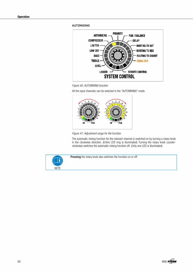
AUTOMIXING
Figure 40: AUTOMIXING function
All the input channels can be selected in the "AUTOMIXING" mode.
Figure 41: Adjustment range for the function
The automatic mixing function for the relevant channel is switched on by turning a rotary knob in the clockwise direction. (Entire LED ring is illuminated) Turning the rotary knob counter-clockwise switches the automatic mixing function off. (Only one LED is illuminated)
NOTE
Pressing the rotary knob also switches the function on or off.

MX6 61
Operation
PRIORITY
Figure 42: PRIORITY function
The "PRIORITY" mode allows you to select which input channel will function as the priority channel. The priority channel then receives a 6 dB advantage in the signal detection in connection with the "AUTOMIXING" function.
Figure 43: Adjustment range for the function
The function for the relevant channel is switched on by turning the rotary knob in the clockwise direction. (Entire LED ring is illuminated) Turning the rotary knob counter-clockwise switches the function off. (Only one LED is illuminated)
NOTE
Pressing the rotary knob also switches the function on or off.
Switching on the "PRIORITY" function on an input channel turns off the function on the previously activated channel.
NOTE
This function can only be active on a single input channel.

62 MX6
Operation
PAN / BALANCE
Figure 44: PAN / BALANCE function
The "PAN / BALANCE" mode allows all the input channels in the panorama and the balance of all the output channels to be controlled.
NOTE
Balance means assignment of a main signal to the output. Changes to the channels just cause attenuation!
Figure 45: Adjustment range for the function
Only the upper middle LED lights up (0 dB) with linear adjustment. This LED (0 dB) is also considered to be the starting point for a clockwise or counter-clockwise rotation. More LEDs light up on the left side as the rotary knob is turned further to the left. More LEDs light up on the right side as the rotary knob is turned further to the right.
If no further output is required from the left output channel of a stereo output, turn the balance controller to the right.
In mono inputs, the signal is assigned equally to stereo left and right as standard. If the input is to be assigned to the left only, turn the rotary knob for the input to the left when the PAN function is active.

MX6 63
Operation
The settings range from 0 dB to -∞ dB.
Figure 46: Increments on the LED ring for the PAN / BALANCE function
The adjustable increments are equal to 6 dB per click and also correspond to one LED.
DELAY
Figure 47: DELAY function
"OUT" can be controlled in the "DELAY" mode. The right output channel can be delayed using this function:
The settings range from 0 m to 75 m. One LED is illuminated at 0 m, while the entire LED ring is illuminated at 75 m.
Figure 48: Increments on the LED ring for the DELAY function
The adjustable increments are equal to 1 m per click. 5 m is equal to one LED.

64 MX6
Operation
ROUTING TO OUT
Figure 49: ROUTING TO OUT function
All the input channels can be controlled in the "ROUTING TO OUT" mode.
Figure 50: Adjustment range for the function
The function for the relevant channel is switched on by turning the rotary knob in the clockwise direction (entire LED ring is illuminated). Turning the rotary knob counter-clockwise switches the function off (only one LED is illuminated).
NOTE
Pressing the rotary knob also switches the function on or off.
Switching this on sets the input channel to the OUT master bus.

MX6 65
Operation
ROUTING TO REC
Figure 51: ROUTING TO REC function
All the input and output channels can be selected in the "ROUTING TO REC" mode.
Figure 52: Adjustment range for the function
The function for the relevant channel is switched on by turning the rotary knob in the clockwise direction (entire LED ring is illuminated). Turning the rotary knob counter-clockwise switches the function off (only one LED is illuminated).
NOTE
Pressing the rotary knob also switches the function on or off.
Switching this on sets the input channel to the REC master bus.

66 MX6
Operation
ROUTING TO DIGOUT
Figure 53: ROUTING TO DIGOUT function
All the input channels can be controlled in the "ROUTING TO DIGOUT" mode.
Figure 54: Adjustment range for the function
The function for the relevant channel is switched on by turning the rotary knob in the clockwise direction (entire LED ring is illuminated). Turning the rotary knob counter-clockwise switches the function off (only one LED is illuminated).
NOTE
Pressing the rotary knob also switches the function on or off.

MX6 67
Operation
Switching this on sets the input channel to the DIGOUT master bus.
EQUALIZER
Figure 55: EQUALIZER function
"OUT 1" and "OUT 2" can be controlled in the "EQUALIZER" mode. The adjustment is the same for the left and right channel.
Figure 56: Adjustment range for the function
The "EQUALIZER" function allows room equalization to be performed in 12 bands. Pressing the "OUT 1" rotary knob activates the "OUT 1" adjustment, while pressing on the "OUT 2" rotary knob activates the "OUT 2" adjustment. The raising or lowering of the bands is performed by the 12 rotary knobs for the input channels.
The adjustment range extends from -14 dB to +14dB. Only the upper middle LED lights up (0 dB) with linear adjustment. More LEDs light up on the left side as the rotary knob is turned further to the left. More LEDs light up on the right side as the rotary knob is turned further to the right.
Figure 57: Increments on the LED ring for the equalizer function
The adjustable increments are equal to 2 dB per click or one LED.

68 MX6
Operation
The centre frequencies of the sub-bands are assigned at half-octave intervals at 250Hz, 350Hz, 500Hz, 700Hz, 1000Hz, 1400Hz, 2000Hz, 2800Hz, 4000Hz, 5600Hz, 8000Hz and 11300Hz. The filter quality is 2.8710.
Figure 58: Adjustment range for the EQUALIZER function
MUTE
Figure 59: Adjustment range for the function
The respective channel is switched to mute by briefly pushing the input or output rotary knob, with the exception of the "HEADPHONE" rotary knob. The MUTE function is indicated by the steady flashing of the LED ring. Another brief press or turn of the rotary knob removes the MUTE function.

MX6 69
Operation
LOCKED
Figure 60: LOCKED function
In LOCKED mode the rotary knobs or the entire unit are protected against improper use by means of locking.
Locking the "SYSTEM CONTROL" rotary knob
The "SYSTEM CONTROL" rotary knob is locked by pressing it (for longer than 3 seconds). The "LOCKED" LED is illuminated. In this case, turning the rotary knob does not change anything. All the other rotary knobs are in the "LEVEL" mode and can continue to be operated as before. Pressing the "SYSTEM CONTROL" rotary knob for longer than 3 seconds removes the locking. The rotary knob will be positioned in the default setting "LEVEL".
Locking the entire unit
The entire unit can be completely locked by simultaneously pressing the "SYSTEM CONTROL" and "OUT" rotary knobs (for longer than 3 seconds!). The original settings will be saved. The "LOCKED" LED on the "SYSTEM CONTROL" rotary knob is illuminated. In this case, turning the rotary knobs does not change anything. The lock can be removed by pressing the "SYSTEM CONTROL" and "OUT" rotary knobs (longer than 3 seconds!). The rotary knobs will be positioned in the default "LEVEL" setting.
Exempting individual channels from locking
If the entire unit has been blocked as described above, you have the option of exempting individual channels from being locked. Only the volume of the excluded channels can then be adjusted. Pressing the rotary knob of the desired channel (for more than 3 seconds) excludes the channel from the locking. Pressing the rotary knob again (for longer than 3 seconds) relocks the channel.
NOTE
The set LOCK states are retained even after switching the MX6 off and on again!
Copy function for configuration data
The copy function can be used to copy individual or multiple setting values (LEVEL, TREBLE, BASS, LOW CUT, LIMITER and COMPRESSOR) from an input to one or more other inputs.
NOTE
The copy process is applied for all the rotary knobs located between the two rotary knobs that have been selected.
Copying individual values
1) Select the function you require using the "SYSTEM CONTROL" rotary knob. 2) Press the rotary knob whose value is to be copied and then immediately press the rotary
knob up to which the copy process is to be performed. 3) Hold down the two rotary knobs (approx. 4 seconds) until you hear a beep and the
affected LED rings flash briefly.

70 MX6
Operation
The value has been transferred to the selected channels.
Copying all values
1) Press the rotary knob whose values are to be copied and then immediately press the rotary knob up to which the copy process is to be performed.
2) Hold down the two rotary knobs (approx. 8 seconds) until you hear a beep-beep and the affected LED rings flash briefly.
All values have been transferred to the selected channels.
NOTE
The copy process can be performed in both directions. ("IN 1" to "IN 6" and "IN 6" to "IN 1")
Figure 61: Select the rotary knob (source)
Figure 62: Define the copy range (target)
Figure 63: Hold down the rotary knobs
Figure 64: Copy process complete

MX6 71
Operation
Resetting the factory settings
Figure 65: Resetting the factory settings
In order to reset the factory settings for the entire device, proceed as follows:
1) Hold down the "SYSTEM CONTROL" rotary knob (until step 5). 2) Turn the unit off with the power switch. 3) Switch the unit on again after a brief waiting period. 4) Wait until the automixer has completed its start sequence (approx. 15 seconds). 5) Release the "SYSTEM CONTROL" rotary knob.
The unit's factory settings have now been restored and a new system configuration can now be set up.
NOTE
Resetting the factory settings deletes all of the stored settings!

72 MX6
Cleaning
Unplug the power supply cable from the socket.
Clean the surface of the unit with a moistened (not wet) cloth.
ATTENTION
Never use caustic or scouring cleaners or cleaning agents containing alcohol or solvents, since these may damage the enamel and plastic parts.
5 Cleaning

MX6 73
Specifications
Dimensions of unit W x H x D 483 x 44 x 203 mm Weight of unit (with packaging) 3.5 kg Permissible ambient temperature in operation + 5 ... + 45°C Minimum humidity in operation 20 % Maximum humidity in operation (non-condensing)
83 %
Input voltage: 100 … 240 V AC Mains frequency: 50 … 60 Hz Power consumption max.: 75 W Output voltages: +5 V DC / +12 V DC / -12 V DC
Balanced inputs - preamp
Gain: 0 dB - 57 dB Input level max.: +20 dBu Common-mode rejection: > 70 dB Dynamic: > 120 dB Signal/noise ratio (S/N) 90 dB Input impedance: > 8 kOhm Equivalent input noise: -127 dBu
Balanced inputs - phantom power
Phantom power: +48 V DC Supply current per input max.: 10 mA Feed resistances: 2 x 6.8 kOhm
Balanced inputs - Analogue Digital Converter
Data format: 24 bit Sample frequency: 48 kHz
Recording and master output
Output level max.: +20 dBu Dynamic: > 110 dB Signal/noise ratio (S/N) 90 dB Load impedance min.: < 100 Ohm
Digital analogue conversion for recording, monitoring and master output
Data format: 24 bit Sample frequency: 48 kHz
This product conforms to the standards listed in the Declaration of Conformity. To view a copy of the Declaration of Conformity for this product, visit http://www.Stemin.com or contact [email protected].
6 Specifications
General
Power supply unit
Inputs
Outputs

74 MX6
Troubleshooting
ATTENTION
RISK OF INJURY! Only authorised personnel may open the device for troubleshooting.
Problem Possible cause Remedy
No sound
Power supply cable is not connected to unit
Connect power supply cable to unit
Power switch off Turn power switch to on position
Unit is not connected to amplifier
Connect output channel to amplifier
Microphone or auxiliary equipment not connected to unit
Connect microphone or auxiliary device to unit
Volume control set to minimum
Turn up volume control
Volume controls set to mute Cancel muting by pressing rotary knob
Pre-amplification not set correctly
Set gain control on rear panel to correct pre-amplification
Phantom power is switched off Switch on phantom power for condenser microphone
external potentiometer set to minimum
Turn up external potentiometer
No sound with sinusoidal feed
Automix algorithm suppressing constant signal
Exclude channel from automix algorithm
Distorted signal reproduction
Pre-amplification not set correctly
Set gain control on rear panel to correct pre-amplification
Volume control turned up too far
Turn down volume
Input signal level too high Reduce input signal
If the error persists despite these instructions, contact STEMIN GMBH GmbH or your STEMIN GMBH dealer immediately.
7 Troubleshooting

MX6 75
Notizen - Notes
8 Notizen - Notes

76 MX6
Notizen - Notes
9 Notizen - Notes


Technische Änderungen vorbehalten. Specifications subject to change without notice.
STEMIN GmbHSTEMIN GmbHSTEMIN GmbHSTEMIN GmbH Hauptstraße 25 D - 82549 Königsdorf Germany Telefon +49 8179 93110 Telefax +49 8179 931199 E-Mail [email protected] web www.stemin.com
For other products and distributors worldwide visit www.stemin.com