BD LSRII Overview Workbook
84
BD Biosciences 2350 Qume Drive San Jose, CA 95131-1807 Draft Rev A September 2002 BD LSRII Overview Workbook
Transcript of BD LSRII Overview Workbook
BD Biosciences2350 Qume Drive
San Jose, CA95131-1807
BD LSRII OverviewWorkbook
Draft Rev ASeptember 2002

ii BD LSRII Overview Workbook Draft
BD Biosciences • 2350 Qume Drive • San Jose, California • 95131-1807
© 2002 Becton, Dickinson and Company. All rights reserved. No part of this publication may be reproduced, transmitted, transcribed, stored in retrieval systems, or translated into any language or computer language, in any form or by any means: electronic, mechanical, magnetic, optical, chemical, manual, or otherwise, without the prior written permission of BD Biosciences, 2350 Qume Drive, San Jose, CA 95131, United States of America.
BD Biosciences reserves the right to change its products and services at any time to incorporate the latest technological developments. Although this guide has been prepared with every precaution to ensure accuracy, BD Biosciences assumes no liability for any errors or omissions, nor for any damages resulting from the application or use of this information. This workbook is subject to change without notice. BD Biosciences welcomes customer input on corrections and suggestions for improvement.
Apple Computer, Inc. makes no warranties whatsoever, either express or implied, regarding this product, including warranties with respect to its merchantability or its fitness for any particular purpose.
Macintosh, Apple, and the Apple logo are registered trademarks of Apple Computer, Inc.
Teflon is a registered trademark of E.I. du Pont de Nemours and Company.
AlignFlow and Texas Red are trademarks of Molecular Probes, Inc.
FlowJo is a trademark of Tree Star, Inc.
BD CaliBRITE, BD CellQuest, BDFACS, BD FACSCalibur, BD FACS Clean, BD FACStation, BD FACS Rinse, BD FACSVantage, and BD Falcon are trademarks of Becton, Dickinson and Company.
For Research Use Only. Not for use in diagnostic or therapeutic procedures.
iiiDraft Copyright

iv BD LSRII Overview Workbook Draft
Table of Contents
1 Introduction . . . . . . . . . . . . . . . . . . . . . . . . . . . . . . . . . . . . . . . . . . . . . . . . 1-1
About the Instrument . . . . . . . . . . . . . . . . . . . . . . . . . . . . . . . . . . . . . . . . . . 1-3
Power Switch . . . . . . . . . . . . . . . . . . . . . . . . . . . . . . . . . . . . . . . . . . . . . 1-3Control Panel . . . . . . . . . . . . . . . . . . . . . . . . . . . . . . . . . . . . . . . . . . . . . 1-4Fluidics . . . . . . . . . . . . . . . . . . . . . . . . . . . . . . . . . . . . . . . . . . . . . . . . . . 1-4Optics . . . . . . . . . . . . . . . . . . . . . . . . . . . . . . . . . . . . . . . . . . . . . . . . . . . 1-9Electronics . . . . . . . . . . . . . . . . . . . . . . . . . . . . . . . . . . . . . . . . . . . . . . . 1-14Software . . . . . . . . . . . . . . . . . . . . . . . . . . . . . . . . . . . . . . . . . . . . . . . . 1-14
Overview . . . . . . . . . . . . . . . . . . . . . . . . . . . . . . . . . . . . . . . . . . . . . . . . . . 1-15
2 Operations and Maintenance . . . . . . . . . . . . . . . . . . . . . . . . . . . . . . . . . . 2-1
Lab Exercise: BD LSRII Startup . . . . . . . . . . . . . . . . . . . . . . . . . . . . . . . . . . 2-3
Lab Exercise: BD LSRII Shutdown . . . . . . . . . . . . . . . . . . . . . . . . . . . . . . . . 2-7
BD LSRII Maintenance and Care Procedures . . . . . . . . . . . . . . . . . . . . . . . . 2-9
Regular Maintenance . . . . . . . . . . . . . . . . . . . . . . . . . . . . . . . . . . . . . . . 2-9Periodic Maintenance . . . . . . . . . . . . . . . . . . . . . . . . . . . . . . . . . . . . . . 2-13Laser Maintenance . . . . . . . . . . . . . . . . . . . . . . . . . . . . . . . . . . . . . . . . 2-18
3 Optics and Lasers . . . . . . . . . . . . . . . . . . . . . . . . . . . . . . . . . . . . . . . . . . . . 3-1
Lasers . . . . . . . . . . . . . . . . . . . . . . . . . . . . . . . . . . . . . . . . . . . . . . . . . . . . . . 3-3
Optical Filters . . . . . . . . . . . . . . . . . . . . . . . . . . . . . . . . . . . . . . . . . . . . . 3-4Optical Filters in the BD LSRII . . . . . . . . . . . . . . . . . . . . . . . . . . . . . . . . 3-4
4 Instrument Quality Control . . . . . . . . . . . . . . . . . . . . . . . . . . . . . . . . . . . . 4-1
Instrument Quality Control . . . . . . . . . . . . . . . . . . . . . . . . . . . . . . . . . . . . . 4-3
Lab Exercise: Performing Quality Control . . . . . . . . . . . . . . . . . . . . . . . . . . 4-4
Preparing the QC Sample . . . . . . . . . . . . . . . . . . . . . . . . . . . . . . . . . . . . 4-4
Appendix A Worksheets . . . . . . . . . . . . . . . . . . . . . . . . . . . . . . . . . . . . . . . . . . . A-1
Appendix B Troubleshooting . . . . . . . . . . . . . . . . . . . . . . . . . . . . . . . . . . . . . . . B-1
BD LSR Overview Course Evaluation . . . . . . . . . . . . . . . . . . . . . . . . . . . . . . . E-1
vDraft Table of Contents

vi BD LSRII Overview Workbook Draft

Draft
1• • • • • • • • • • • • • • • • • • • • • • • • • • • • • • • • • • • • • • • • • • • • • • • • • • • • • • • • • • • •
Introduction
After completing this module, you will be able to:
◆
describe the three systems of a flow cytometer
◆
describe the anatomy BD LSRII flow cytometer

1-2
BD LSRII Overview Workbook Draft
About the Instrument
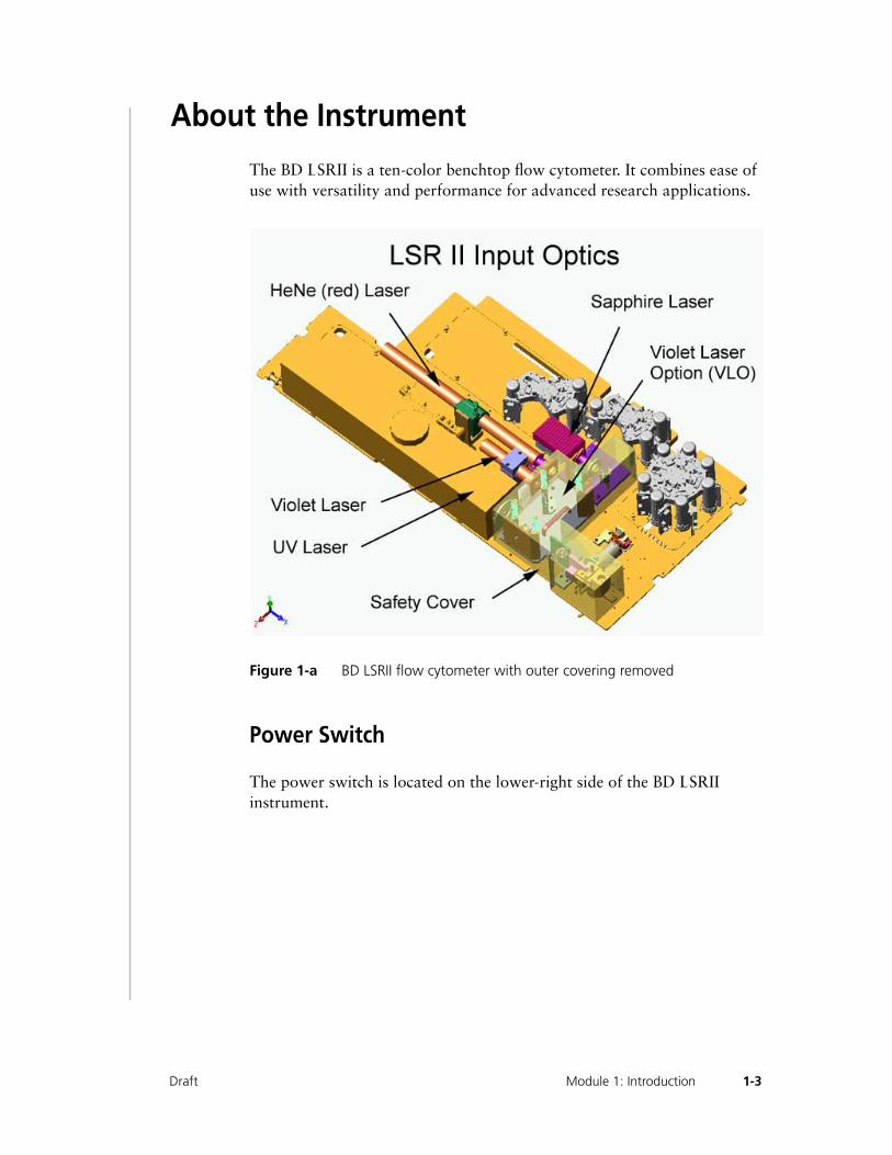
The BD LSRII is a ten-color benchtop flow cytometer. It combines ease of use with versatility and performance for advanced research applications.
Figure 1-a BD LSRII flow cytometer with outer covering removed
Power Switch
The power switch is located on the lower-right side of the BD LSRII instrument.
1-3Draft Module 1: Introduction
Control Panel
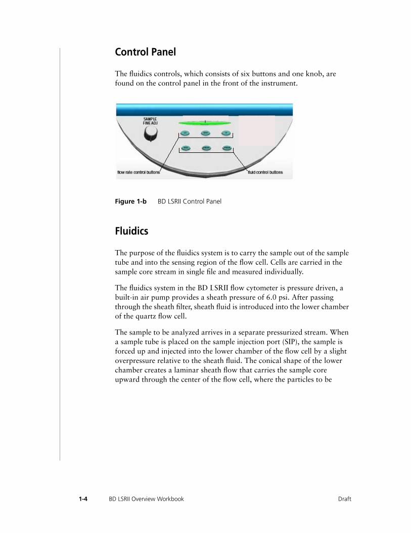
The fluidics controls, which consists of six buttons and one knob, are found on the control panel in the front of the instrument.
Figure 1-b BD LSRII Control Panel
Fluidics
The purpose of the fluidics system is to carry the sample out of the sample tube and into the sensing region of the flow cell. Cells are carried in the sample core stream in single file and measured individually.
The fluidics system in the BD LSRII flow cytometer is pressure driven, a built-in air pump provides a sheath pressure of 6.0 psi. After passing through the sheath filter, sheath fluid is introduced into the lower chamber of the quartz flow cell.
The sample to be analyzed arrives in a separate pressurized stream. When a sample tube is placed on the sample injection port (SIP), the sample is forced up and injected into the lower chamber of the flow cell by a slight overpressure relative to the sheath fluid. The conical shape of the lower chamber creates a laminar sheath flow that carries the sample core upward through the center of the flow cell, where the particles to be
1-4 BD LSRII Overview Workbook Draft
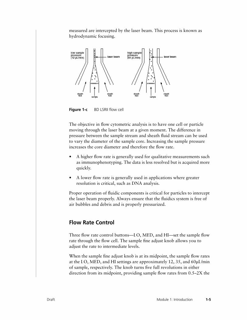
measured are intercepted by the laser beam. This process is known as hydrodynamic focusing.
Figure 1-c BD LSRII flow cell
The objective in flow cytometric analysis is to have one cell or particle moving through the laser beam at a given moment. The difference in pressure between the sample stream and sheath fluid stream can be used to vary the diameter of the sample core. Increasing the sample pressure increases the core diameter and therefore the flow rate.
• A higher flow rate is generally used for qualitative measurements such as immunophenotyping. The data is less resolved but is acquired more quickly.
• A lower flow rate is generally used in applications where greater resolution is critical, such as DNA analysis.
Proper operation of fluidic components is critical for particles to intercept the laser beam properly. Always ensure that the fluidics system is free of air bubbles and debris and is properly pressurized.
Flow Rate Control
Three flow rate control buttons—LO, MED, and HI—set the sample flow rate through the flow cell. The sample fine adjust knob allows you to adjust the rate to intermediate levels.
When the sample fine adjust knob is at its midpoint, the sample flow rates at the LO, MED, and HI settings are approximately 12, 35, and 60µL/min of sample, respectively. The knob turns five full revolutions in either direction from its midpoint, providing sample flow rates from 0.5–2X the
1-5Draft Module 1: Introduction
midpoint value. For example, if the LO button is pressed, the knob will give flow rates from approximately 6–24 µL/min.
Fluid Control
Three fluid control buttons—RUN, STNDBY, and PRIME—set the instrument operation mode:
• RUN pressurizes the sample tube to transport the sample through the sample injection tube and into the flow cell. The RUN button is green when the sample tube is on and the support arm is centered. When the tube support arm is moved left or right to remove a sample tube, the instrument switches to an automatic standby status to conserve sheath fluid—the RUN button changes to orange.
• STNDBY (standby) restricts fluid flow to conserve sheath fluid. When leaving the instrument for more than a few minutes, place a tube containing 1 mL of deionized water on the sample injection port (SIP) and press STNDBY.
• PRIME prepares the fluidics to begin a run by draining and filling the flow cell with sheath fluid. The fluid flow initially stops and pressure is reversed to force fluid out of the flow cell and into the waste container. After a preset time, the flow cell fills with sheath fluid at a controlled rate to prevent bubble formation or entrapment. At completion, the instrument switches to STNDBY mode.
Sample Injection Port
The sample injection port (SIP) is where the sample tube is installed. The SIP includes the sample injection tube and the tube support arm. Samples are introduced through a stainless steel injection tube equipped with an outer droplet containment sleeve. The sleeve works in conjunction with a
1-6 BD LSRII Overview Workbook Draft
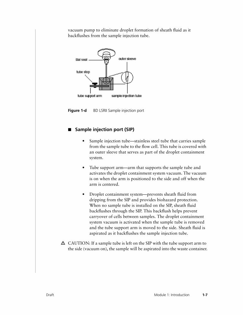
vacuum pump to eliminate droplet formation of sheath fluid as it backflushes from the sample injection tube.
Figure 1-d BD LSRII Sample injection port
■ Sample injection port (SIP)
• Sample injection tube—stainless steel tube that carries sample from the sample tube to the flow cell. This tube is covered with an outer sleeve that serves as part of the droplet containment system.
• Tube support arm—arm that supports the sample tube and activates the droplet containment system vacuum. The vacuum is on when the arm is positioned to the side and off when the arm is centered.
• Droplet containment system—prevents sheath fluid from dripping from the SIP and provides biohazard protection. When no sample tube is installed on the SIP, sheath fluid backflushes through the SIP. This backflush helps prevent carryover of cells between samples. The droplet containment system vacuum is activated when the sample tube is removed and the tube support arm is moved to the side. Sheath fluid is aspirated as it backflushes the sample injection tube.
m CAUTION: If a sample tube is left on the SIP with the tube support arm to the side (vacuum on), the sample will be aspirated into the waste container.
1-7Draft Module 1: Introduction
Sheath and Waste Tanks
The sheath and waste tanks are outside the instrument. They should be kept in the same location the field service engineer placed them at installation. Moving the tanks to a different location, i.e. from the floor to the benchtop, will change the sheath velocity.
The sheath tank is a metal container with a capacity of 8 L. Sheath fluid is filtered through an in-line, interchangeable filter that prevents small particles from entering the sheath fluid lines. The sheath filter is located on top of the sheath tank.
Before opening the sheath tank:
1 Put the instrument in STNDBY mode.
2 Disconnect the air line (green).
3 Depressurize the sheath tank by lifting its vent cap.
The waste tank is plastic container with a capacity of 10 L. The waste tank is equipped with a waste management system that consists of a base and an overfull sensor. The base holds the waste tank and is equipped with magnets to hold the base to the leg of a metal bench or table to prevent tipping. The overfull sensor will emit an audible alarm when the waste is full. To test the alarm, press the test button on the base.
H WARNING: To avoid leakage of biohazardous waste, put the instrument in STNDBY mode before disconnecting the waste container.
H WARNING: The waste container contents might be biohazardous. Treat contents with bleach (10% of total volume). Dispose of waste with proper precautions in accordance with local regulations. Wear suitable protective clothing, eyewear, and gloves.
Recommended Sheath Fluids
• BD FACS Flow™ sheath fluid (BD Biosciences, Catalog no. 342003)
• Phosphate-buffered saline (PBS) (Dulbecco’s Ca++-free and Mg++-free) for certain applications
1-8 BD LSRII Overview Workbook Draft
Non -Recommended Sheath Fluids
• Fisher Hematology Diluent
• Isoton III
• Isolac D
• Deionized water
NOTE: If you make your own sheath fluid in the lab, be sure to pass it through a 0.22-um filter before running it on the BD LSRII instrument.
Optics
The optics consists of:
• lasers that generate excitation light
• filters and mirror that route the laser light to the fluidic stream
• fiber optic cables that direct the resulting light scatter and fluorescence signals to the appropriate emission block
• filters that direct the light scatter and fluorescence signals in the emission block to the appropriate PMT
Light Scatter
When a cell or particle passes through a focused laser beam, laser light is scattered in all directions. Light that scatters axial to the laser beam is called forward scatter (FSC); light that scatters perpendicular to the laser beam is called side scatter (SSC). FSC and SSC are related to certain physical properties of cells:
• FSC—indicates relative differences in the size of the cells or particles
• SSC—indicates relative differences in the internal complexity or granularity
1-9Draft Module 1: Introduction
Fluorescence
When cells or particles stained with fluorochrome-conjugated antibodies or other dyes pass through a laser beam, the dyes can absorb photons (energy) and be promoted to an excited electronic state. In returning to their ground state, they release energy, most of which is emitted as light. This light emission is known as fluorescence.
Fluorescence is always a longer wavelength (lower-energy photon) than the excitation wavelength. The difference between the excitation wavelength and the emission wavelength is known as the Stokes shift. Some fluorescent compounds such as PerCP exhibit a large Stokes shift, absorbing blue light (488 nm) and emitting red light (675 nm), while other fluorochromes such as FITC have a smaller Stokes shift, absorbing blue light and emitting green light (530 nm).
Lasers
The basic BD LSRII flow cytometer has fixed alignment, 488-nm laser excitation optics. Up to three additional lasers can be added. All of the optional lasers are also alignment-free.
• The primary, Coherent Sapphire, solid state 488nm laser generates forward scatter (FSC) and side scatter (SSC–PMT1) signals and up to four fluorescence signals—, PMT2, PMT3, PMT4, and PMT5
• The optional VioFlame 405nm laser generates two fluorescence signals—PMT6 and PMT7
• The optional Kimmon HeCd 325nm or Lightwave solid state 355nm laser generates two fluorescence signals—PMT8 and PMT9
• The optional JDS Uniphase HeNe 633nm laser generates two fluorescence signals—PMT10 and PMT11
m CAUTION: To extend the life of the HeCd laser, turn on the instrument for at least 4 hours at least once per week.
1-10 BD LSRII Overview Workbook Draft
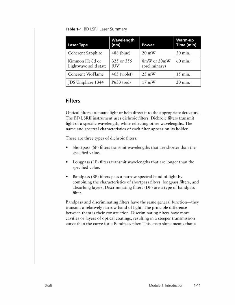
Table 1-1 BD LSRII Laser Summary
Filters
Optical filters attenuate light or help direct it to the appropriate detectors. The BD LSRII instrument uses dichroic filters. Dichroic filters transmit light of a specific wavelength, while reflecting other wavelengths. The name and spectral characteristics of each filter appear on its holder.
There are three types of dichroic filters:
• Shortpass (SP) filters transmit wavelengths that are shorter than the specified value.
• Longpass (LP) filters transmit wavelengths that are longer than the specified value.
• Bandpass (BP) filters pass a narrow spectral band of light by combining the characteristics of shortpass filters, longpass filters, and absorbing layers. Discriminating filters (DF) are a type of bandpass filter.
Bandpass and discriminating filters have the same general function—they transmit a relatively narrow band of light. The principle difference between them is their construction. Discriminating filters have more cavities or layers of optical coatings, resulting in a steeper transmission curve than the curve for a Bandpass filter. This steep slope means that a
Laser TypeWavelength (nm) Power
Warm-up Time (min)
Coherent Sapphire 488 (blue) 20 mW 30 min.
Kimmon HeCd or Lightwave solid state
325 or 355 (UV)
8mW or 20mW (preliminary)
60 min.
Coherent VioFlame 405 (violet) 25 mW 15 min.
JDS Uniphase 1344 P633 (red) 17 mW 20 min.
1-11Draft Module 1: Introduction
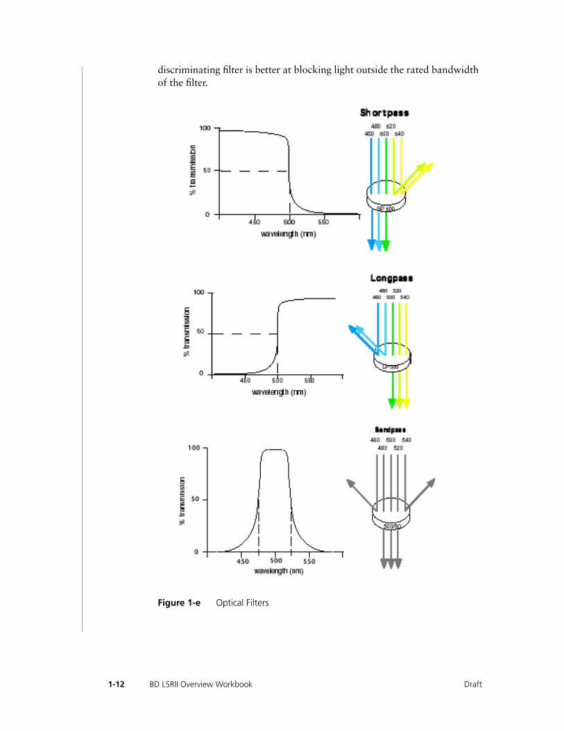
discriminating filter is better at blocking light outside the rated bandwidth of the filter.
Figure 1-e Optical Filters
1-12 BD LSRII Overview Workbook Draft
When dichroic filters are used as steering optics to direct different color light signals to different detectors, they are called dichroic mirrors or beam splitters.
• Shortpass dichroic mirrors transmit shorter wavelengths of light to one detector while reflecting longer wavelengths to a different detector.
• Longpass dichroic mirrors transmit longer wavelengths to one detector while reflecting shorter wavelengths to a different detector.
The default optical configuration on the BD LSRII uses all longpass dichroic mirrors to direct the light to the appropriate PMT.
Detectors
Light signals are generated as particles pass through the laser beam in a fluid stream. When these optical signals (photons) reach a detector they are converted to electrical pulses. The electrical pulses then are digitized into one of 16,384 possible levels 10 millions times per second by analog-to-digital converters. The digital signal is then further processed by the electronics system.
There are two types of signal detectors in the BD LSRII flow cytometer: the photodiode and photomultiplier tubes (PMTs). The photodiode is less sensitive to light signals than the PMTs, thus is used to detect the stronger FSC signal. PMTs are used to detect the weaker signals generated by SSC and all fluorescence channels. These signals are amplified by applying a voltage to the PMTs. As the voltage is increased, the detector sensitivity increases, resulting in increased signal. As the voltage is decreased, the detector sensitivity decreases, resulting in decreased signal. Detector voltages are adjusted in the Instrument Settings Inspector in the DigFACS software, as described on page 71 of the FACSDiva User’s Guide.
Emission Blocks
Emission blocks house the PMTs and the dichroic and bandpass filters used to direct emitted light. There are two types of emission blocks in the BD LSRII flow cytometer: the octagon and trigon blocks. The octagon emission block is used for light excited by the 488nm laser. An octagon can house up to seven different PMTs, measuring up to 6 fluorescent channels and side scatter light. The trigon emission blocks are used for
1-13Draft Module 1: Introduction

light excited by the UV, 405nm, and 633nm lasers. Each trigon can house up to two PMTs, measuring two fluorescent channels.
Electronics
The digital electronics found in the BD LSRII digitizes the amount of light signals created by particles passing through the laser beams. The voltage corresponding to each signal is digitized continuously during operation and is represented as numbers in the computer’s memory.
Threshold
The threshold defines the level at which the system starts to look for pulses. The system continuously monitors the data and simultaneously calculates area and height for all channels each time a signal exceeds the threshold.
Software
The BD DigiFACS installer installs the following applications:
• BD DigiFACS software, for acquiring and analyzing data
• Data Manager utility, for backing up, archiving, and restoring data
• Sentinel System Driver, needed to use the security module see: Chapter 2: BD FACSDiVa Software Setup 31in the FACSDiva User’s Guide
• Java™ 2 Runtime Environment (JRE), needed to run BD DigiFACS software
• Sybase™ SQL Anywhere™ Studio, needed to run the database
• Adobe® Acrobat® Reader, needed to view the PDF version of the user’s guide
1-14 BD LSRII Overview Workbook Draft

Overview
Control Panel
1 Briefly describe each of the fluid control buttons shown in Figure 1-f.
Figure 1-f
RUN
________________________________________________________
________________________________________________________
________________________________________________________
STNDBY
________________________________________________________
________________________________________________________
________________________________________________________
PRIME
________________________________________________________
________________________________________________________
________________________________________________________
1-15Draft Module 1: Introduction

2 The sample flow rate control buttons (Fig. 6-1) set the sample flow rate through the flow cell. How do you get a flow rate of approximately 17uL/min?
________________________________________________________
________________________________________________________
________________________________________________________
3 What is the flow rate range for the HI setting?
________________________________________________________
Sample Injection Port
The sample injection port (SIP) is where the sample tube is installed. The droplet containment system (DCS) prevents sheath fluid from dripping from the SIP and provides biohazard protection.
1 What happens if the tube support arm is directly under the sample tube and the cytometer is in STNDBY?
________________________________________________________
________________________________________________________
________________________________________________________
2 What happens if the tube support arm is left to the side when a sample tube is on the SIP?
________________________________________________________
________________________________________________________
________________________________________________________
1-16 BD LSRII Overview Workbook Draft

Sheath and Waste Tanks
1 Where should the sheath and waste tanks be placed?
________________________________________________________
2 What is the capacity of the sheath tank and the waste tank?
________________________________________________________
3 The instrument must be left in ________________ before disconnecting the waste container.
1-17Draft Module 1: Introduction

1-18 BD LSRII Overview Workbook Draft
Draft
2• • • • • • • • • • • • • • • • • • • • • • • • • • • • • • • • • • • • • • • • • • • • • • • • • • • • • • • • • • • •
Operations and Maintenance
After completing this module, you will be able to:
◆
Perform the startup and shutdown procedures
◆
Describe the regular maintenance and periodic maintenance procedures

2-2
BD LSRII Overview Workbook Draft
Lab Exercise: BD LSRII Startup
It will take approximately 10 minutes to complete the startup procedure.
1 Turn on the BD LSRII.
The power switch is located on the lower right corner of the instrument. The LO fluid control button lights green and the STNDBY button lights orange.
The 488nm Sapphire laser requires a 30-minute warm-up; the HeCd UV laser requires a 60-minute warm-up; the 405nm VioFlame laser requires a 15 minute warm-up; and the HeNe requires a 20-minutes warm-up before running samples.
2 Turn on the computer.
Filling the Sheath Tank
1 Make sure the cytometer is in STNDBY mode, and then disconnect the green tubing line that connects to the sheath tank.
Putting the instrument in STNDBY mode before disconnecting the green line prevents leakage. The green line supplies the air to pressurize the tank.
2 Depressurize the sheath tank by slowly pulling up on the pressure relief valve.
3 Remove the lid of the sheath tank.
4 Fill the tank with sheath fluid.
Typically an isotonic saline solution is used as sheath fluid. BD FACSFlow solution (BD Biosciences Catalog No. 342003) is recommended and used as sheath fluid during the training course.
2-3Draft Module 2: Operation and Maintenance

m CAUTION: Avoid filling the sheath tank to its maximum capacity. When a full tank is pressurized, fluid can be forced into the air supply tubing, preventing proper pressurization.
5 Replace the sheath tank lid.
To ensure proper pressurization when replacing the lid, make sure it is tightened well.
6 Replace the green air line to the sheath tank.
Emptying the Waste Tank
Use appropriate safety apparel such as lab coat, gloves, and mask, when emptying the waste tank.
m CAUTION: It is good practice to empty the waste tank when the sheath tank is filled. This prevents the waste tank from overflowing.
1 Disconnect the orange line from the waste tank.
2 Remove the lid of the waste tank.
3 Empty the contents of the waste tank into an appropriate waste receptacle.
4 Add bleach to the waste tank.
Add a sufficient quantity of bleach to obtain a minimum 10% final concentration of bleach.
5 Replace the waste tank lid and reconnect the orange line to the orange connector on the waste tank.
Removing Air Bubbles
First, bubbles will be removed from the fluidics lines.
2-4 BD LSRII Overview Workbook Draft
1 Check the sheath filter for trapped air bubbles.
2 If bubbles are visible, gently tap the filter body with your fingers to dislodge the bubbles and force them to the top.
3 Firmly pinch the tubing between your fingers and loosen the sheath filter’s vent cap to bleed off any air in the filter.
4 Collect the excess fluid in an appropriate container, and replace the cap.
NOTE: To remove stubborn bubbles, squeeze the metal clip under the sheath filter and pull the sheath filter from the lower quick-disconnect port. Lift up the filter and firmly tap the filter body to dislodge the bubbles. Reconnect the filter to its lower quick-disconnect port. Firmly pinch the tubing between your fingers and loosen the sheath filter’s vent cap to bleed off any air in the filter.
5 Check the sheath lines for air bubbles.
6 Push the roller in the pinchcock forward to bleed off any air in the lines.
The pinchcock is located on the right side of the instrument, near the fluidics interconnection.
7 Return the pinchcock to the closed position.
Priming the Fluidics
Now you will remove air bubbles from the flow cell.
NOTE: Also perform this procedure if quality control (QC) results are outside of your established range.
2-5Draft Module 2: Operation and Maintenance
1 Remove the tube of deionized (DI) water from the sample injection port (SIP).
2 Press the PRIME fluid control button to force the fluid out of the flow cell and into the waste tank.
Once drained, the flow cell automatically fills with sheath fluid at a controlled rate to prevent bubble formation or entrapment. The STNDBY button lights yellow after priming is complete.
3 Install a 12 x 75-mm tube with 1 mL of DI water on the SIP and place the support arm under the tube.
2-6 BD LSRII Overview Workbook Draft

Lab Exercise: BD LSRII Shutdown
It will take approximately 15 minutes to complete the shutdown procedure.
Always clean the BD LSRII instrument before it is turned off at the end of the day. Proper cleaning will ensure that your instrument will function consistently. Cleaning prevents the sample injection tube from becoming clogged and removes dyes that could remain in the tubing, causing carryover.
Follow this procedure immediately after running viscous samples or nucleic acid dyes such as Hoechst, DAPI, propidium iodide (PI), acridine orange (AO), or thiazole orange (TO).
Bleaching the Droplet Containment Tube and the Sample Injection Tube
NOTE: Make sure the sample fine adjust knob is at the middle flow rate position or greater for the entire cleaning procedure.
1 Set the fluid control to RUN.
2 Install a tube containing 3 mL of a bleach solution on the SIP with the support arm to the side (vacuum is on), and let it run 1 minute.
Use BD FACS Clean (BD Biosciences, Catalog No. 340345) or a 1:10 dilution of bleach in DI water as the bleach solution.
BD FACS Clean is a bleach-based cleaning agent for daily use in cytometer maintenance.
3 Move the support arm under the tube (vacuum is off) and allow the bleach solution to run for 5 minutes on HI.
2-7Draft Module 2: Operation and Maintenance
Rinsing the Droplet Containment Tube and the Sample Injection Tube
1 Install a tube containing 3 mL of DI water on the SIP with the support arm to the side (vacuum is on) and let it run for 1 minute.
2 Move the support arm under the tube (vacuum is off) and allow the water to run for 5 minutes on HI.
3 Set the fluid control to STNDBY.
4 Place a tube containing no more than 1 mL of DI water on the SIP.
A tube with 1 mL of DI should remain on the SIP to prevent salt deposits from forming in the injection tube. The tube also catches back drips from the flow cell.
m CAUTION: Do not leave more than 1 mL of water on the SIP. When the BD LSRII flow cytometer is turned off or left in STNDBY mode, a small amount of fluid will drip back into the sample tube. If there is too much fluid in the tube, it could overflow and affect instrument performance.
5 If you are finished running samples for the day, turn off the computer and cytometer.
Choose Start > Shut Down to turn off the computer. Shut off the power to the BD LSRII.
2-8 BD LSRII Overview Workbook Draft

BD LSRII Maintenance and Care Procedures
The BD LSRII instrument is designed to require minimum maintenance. However, to preserve the reliability of the instrument you must regularly perform basic preventive maintenance procedures.
WARNING: All biological specimens and materials coming into contact with them are considered biohazardous. Handle as if capable of transmitting infection. Dispose of these specimens and materials using proper precautions and in accordance with local regulations. Never pipette by mouth. Wear suitable protective clothing, eyewear, and gloves.
Regular Maintenance
Regular maintenance of the cytometer includes performing the shutdown procedure, as described in the previous section. Additionally or alternatively, you can perform the procedures described in the table below, as necessary.
Table 2-1 BD LSRII maintenance procedures
NOTE: If the instrument will not be used for a week or longer, perform the system flush or the bleach flush and leave the fluidics system filled with DI water to prevent saline crystals from clogging the fluidics.
Procedure When
Daily Shutdown Perform procedure after the last sample of the day. Additionally, if DNA dyes, adherent cells, or viscous samples are run, perform the procedure immediately after samples are run.
Bi-Monthly Bleach Flush
Perform bi-monthly as part of the normal maintenance of the LSRII or more often if sticky dyes, adherent cells, or viscous samples are run frequently.
Optional System Flush
Perform as an alternate method to the bi-monthly bleach flush procedure.
2-9Draft Module 2: Operation and Maintenance

Bi-Monthly Bleach Flush Procedure
1 Remove the sheath filter.
Refer to Changing the Sheath Filter on page 23 in this workbook for sheath filter removal instructions.
m CAUTION: Do not run detergent or bleach through the sheath filter. They can break down the filter paper within the filter body, causing particles to escape into the sheath fluid and possibly clogging the flow cell.
2 Empty the sheath tank and rinse it with DI water.
3 Fill the sheath tank with at least 1 L of a bleach solution.
Use BD FACS Clean (BD Biosciences, Catalog No. 340345) or a 1:10 dilution of bleach in DI water as the bleach solution.
BD FACS Clean is a bleach-based cleaning agent for daily use in cytometer maintenance.
4 Empty the waste tank if it is full.
5 Remove the DI water tube from the SIP.
6 Prime twice.
Press the PRIME button on the fluidics control panel. When the STNDBY button lights orange, press the PRIME button again.
7 Install a tube with 3 mL of a bleach solution.
Use BD FACS Clean or a 1:10 dilution of bleach in DI water as the bleach solution.
2-10 BD LSRII Overview Workbook Draft
8 Press the RUN fluid control button and run on HI for 30 minutes.
NOTE: Make sure the sample fine adjust knob is at the middle flow rate position.
9 Press the STNDBY fluid control button, and depressurize the sheath tank by slowly lifting the pressure relief valve cap.
10 Repeat steps 2 through 9 with DI water.
11 Replace the sheath filter and refill the sheath tank with sheath fluid.
12 Remove the DI water tube from the SIP.
13 Prime twice.
14 Place a tube containing no more than 1 mL of DI water on the SIP.
15 Before running samples, allow sheath fluid to run for approximately 5 minutes.
Optional System Flush Procedure
Perform this procedure as an alternative to the bi-monthly bleach flush. This procedure has an additional rinse step that uses BD FACS Rinse, a detergent-based solution.
1 Remove the sheath filter.
Refer to Changing the Sheath Filter on page 23 in this workbook for sheath filter removal instructions.
m CAUTION: Do not run detergent or bleach through the sheath filter. They can break down the filter paper within the filter body, causing particles to escape into the sheath fluid and possibly clogging the flow cell.
2-11Draft Module 2: Operation and Maintenance

2 Empty the sheath tank and rinse it with DI water.
3 Fill the sheath tank with at least 1 L of a bleach solution.
Use BD FACS Clean (BD Biosciences, Catalog No. 340345) or a 1:10 dilution of bleach in DI water as the bleach solution.
4 Empty the waste tank if it is full.
5 Remove the DI water tube from the SIP.
6 Prime twice.
Press the Prime button on the fluidics control panel. When the STNDBY button lights orange, press the Prime button again.
7 Install a tube with 3 mL of bleach solution.
Use BD FACS Clean or a 1:10 dilution of bleach in DI water as the bleach solution.
8 Press the RUN fluid control button and run on HI for 30 minutes.
NOTE: Make sure the sample fine adjust knob is at the middle flow rate position.
9 Press the STNDBY fluid control button, and depressurize the sheath tank by slowly lifting the pressure relief valve cap.
10 Repeat steps 2 through 9 with BD FACS Rinse.
BD FACS Rinse (BD Biosciences, Catalog No. 340346) is a detergent-based cleaning agent.
11 Repeat steps 2 through 9 with DI water.
2-12 BD LSRII Overview Workbook Draft

12 Replace the sheath filter and refill the sheath tank with sheath fluid.
13 Remove the tube of DI water from the SIP.
14 Prime twice.
15 Leave a tube containing no more than 1 mL of DI water on the SIP.
16 Before running samples, allow sheath fluid to run for approximately 5 minutes.
Periodic Maintenance
There are several instrument components that should be checked occasionally and cleaned as necessary. The frequency will depend on how often the instrument is run. Other components should be checked periodically for wear and replaced if necessary.
H WARNING: Follow good laboratory practices; wear protective clothing, eyewear, and gloves whenever cleaning the instrument or replacing parts. Use the information in the table below to determine when to perform periodic maintenance procedures.
Table 2-2 BD LSRII Periodic maintenance procedures
Procedure When
Changing the sheath filter
Perform every 3–6 months.
Changing the Bal seal
Replacement is necessary if a proper seal is not formed when a sample tube is installed on the SIP.
Changing the sample tube O-ring
Replace the O-ring when droplets form at the end of the sample injection tube while the vacuum is operating.
2-13Draft Module 2: Operation and Maintenance
Changing the Sheath Filter
The sheath filter located on top of the sheath container, filters the sheath fluid as it comes from the sheath container. Increased debris appearing in an FSC vs. SSC plot can indicate that the sheath filter (Catalog No. 343542) needs to be replaced. We recommend changing the sheath filter every 3–6 months.
H WARNING: To avoid spraying of sheath fluid, depressurize the sheath container before opening it.
To change the sheath filter:
1 Turn off the instrument.
2 Depressurize the sheath container by lifting its vent cap.
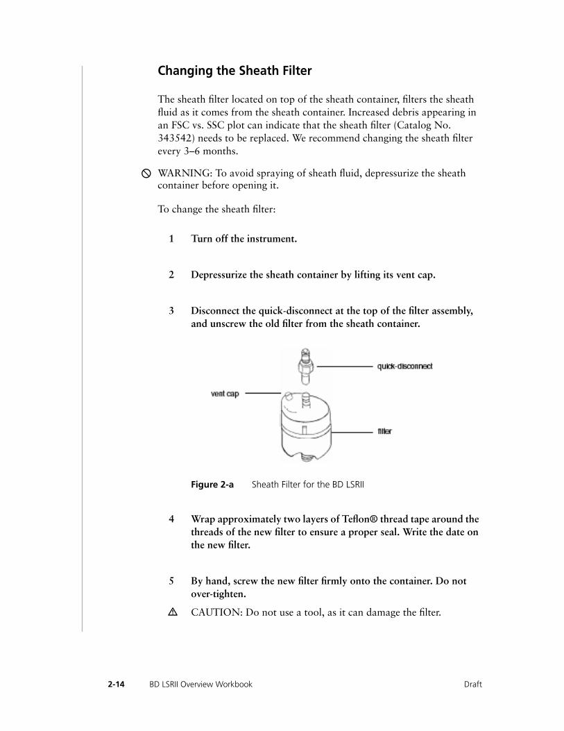
3 Disconnect the quick-disconnect at the top of the filter assembly, and unscrew the old filter from the sheath container.
Figure 2-a Sheath Filter for the BD LSRII
4 Wrap approximately two layers of Teflon® thread tape around the threads of the new filter to ensure a proper seal. Write the date on the new filter.
5 By hand, screw the new filter firmly onto the container. Do not over-tighten.
m CAUTION: Do not use a tool, as it can damage the filter.
2-14 BD LSRII Overview Workbook Draft
6 Connect the quick-disconnect.
7 Turn on the instrument to pressurize the sheath container.
8 Loosen the filter’s vent cap to bleed off any air in the sheath filter.
9 Carefully tap the filter assembly to dislodge any air trapped in the filter element.
10 Loosen the filter’s vent cap again to bleed off any air in the sheath filter.
Changing the Bal Seal
The sample injection tube Bal seal (Catalog No. 343509) is a Teflon ring that forms a seal with the sample tube and ensures proper tube pressurization. Over time, this seal becomes worn or cracked and requires replacement. Replacement is necessary if a proper seal is not formed when a sample tube is installed on the SIP.
To change the Bal Seal:
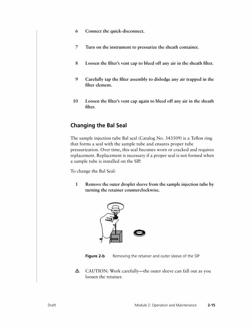
1 Remove the outer droplet sleeve from the sample injection tube by turning the retainer counterclockwise.
Figure 2-b Removing the retainer and outer sleeve of the SIP
m CAUTION: Work carefully—the outer sleeve can fall out as you loosen the retainer.
2-15Draft Module 2: Operation and Maintenance
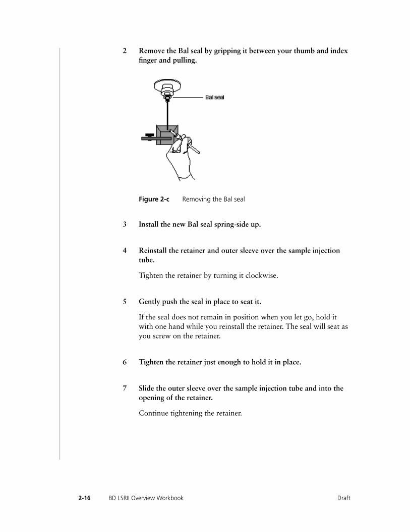
2 Remove the Bal seal by gripping it between your thumb and index finger and pulling.
Figure 2-c Removing the Bal seal
3 Install the new Bal seal spring-side up.
4 Reinstall the retainer and outer sleeve over the sample injection tube.
Tighten the retainer by turning it clockwise.
5 Gently push the seal in place to seat it.
If the seal does not remain in position when you let go, hold it with one hand while you reinstall the retainer. The seal will seat as you screw on the retainer.
6 Tighten the retainer just enough to hold it in place.
7 Slide the outer sleeve over the sample injection tube and into the opening of the retainer.
Continue tightening the retainer.
2-16 BD LSRII Overview Workbook Draft
8 Install a sample tube on the SIP to ensure that the outer sleeve has been properly installed.
If the sleeve hits the bottom of the tube, loosen the retainer slightly and push the sleeve up as far as it will go. Retighten the retainer.
Changing the Sample Tube O-Ring
The sample tube O-ring (Catalog No. 343615), located within the retainer, forms a seal that allows the droplet containment vacuum to function properly. Replace the O-ring when droplets form at the end of the sample injection tube while the vacuum is operating.
H WARNING: Instrument hardware might be contaminated with biohazardous material. Wear suitable protective clothing, eyewear, and gloves whenever cleaning the instrument or replacing parts.
To change the Sample Tube O-Ring:
1 Remove the outer droplet sleeve from the sample injection tube.
Turn the retainer counterclockwise and pull the outer sleeve from the retainer.
2 Invert the retainer and allow the O-ring to fall onto the benchtop.
If the O-ring does not fall out initially, tap the retainer on the benchtop to dislodge the O-ring.
3 Drop the new O-ring into the retainer.
Make sure the O-ring is seated properly in the bottom of the retainer.
4 Reinstall the retainer and the outer sleeve.
Tighten the retainer enough to hold it in place, and slide the outer sleeve over the sample injection tube, into the opening of the retainer. Continue tightening the retainer.
2-17Draft Module 2: Operation and Maintenance
5 Install a sample tube on the SIP to ensure that the outer sleeve has been properly installed.
If the sleeve hits the bottom of the tube, loosen the retainer slightly and push the sleeve up as far as it will go. Retighten the retainer.
Laser Maintenance
To extend the life of the HeCd laser, turn on the instrument for at least 4 continuous hours once per week.
Frequent startup and shutdown might cause damage to the laser tube.
■ TIPS
• Do not shutdown the BD LSRII cytometer within 30 minutes after the latest startup.
• After shutting the BD LSRII cytometer off, wait 30 minutes before restart.
2-18 BD LSRII Overview Workbook Draft
Draft
3• • • • • • • • • • • • • • • • • • • • • • • • • • • • • • • • • • • • • • • • • • • • • • • • • • • • • • • • • • • •
Optics and Lasers
After completing this module, you will be able to:
◆
List optical filters and lasers used in a BD LSRII
◆
Describe the Octagon and Trigon optical pathways

3-2
BD LSRII Overview Workbook Draft
Lasers
The BD LSRII flow cytometer has alignment-free excitation and emission optics.
Using the information found in the introduction portion of this workbook (Module 1) enter the type and wavelength for each laser:
Table 3-1 BDLSRII Laser Configuration
a Do not shutdown the BD LSR cytometer within 30 minutes after the latest startup. After shutting the BD LSR cytometer off, wait 30 minutes before restart.
The primary, argon-ion, laser generates forward scatter (FSC) and side scatter (SSC) signals and up to four fluorescence signals. Name the four fluorescence signals.
______________________________________________________________
______________________________________________________________
The UV laser generates two fluorescence signals, _____________ and _____________.
The VioFlame laser generates two fluorescence signals, _____________ and _____________.
The HeNe laser generates two fluorescence signals, _____________ and _____________.
To extend the life of the HeCd laser, the instrument should be turned on for _____________ hours at least once per week.
Laser TypeWavelength (nm) Power
Warm-up Time (min)
Coherent Sapphire ____________ 20 mW ______ min.
Kimmon IK Seriesa or Lightwave solid state
____________
8mW or 20mW (preliminary) ______ min.
Coherent VioFlame ____________ 25 mW ______ min.
JDS Uniphase HeNe ____________ 17 mW ______ min.
3-3Draft Module 3: Optics and Lasers
Optical Filters
H WARNING: Optical filters should be changed only by BD Biosciences–trained operators or by BD Biosciences service personnel.
Using the information found in the introduction portion of this workbook (Module 1), answer the following questions:
1 Name the three types of dichroic mirrors.
________________________________________________________
________________________________________________________
2 What is the main difference between a bandpass filter and a discriminating filter?
________________________________________________________
________________________________________________________
3 A dichroic mirror is used to absorb light and prevent it from getting to the detectors. T F
4 The dichroic mirrors on a BD LSRII flow cytometer require daily alignment. T F
Optical Filters in the BD LSRII
Table 3-2 describes the optical filters used for various fluorochromes with the BD LSRII. The PMT# corresponds to the PMT on the emission block, the channel corresponds to the channel in the DigiFACS software.
3-4 BD LSRII Overview Workbook Draft
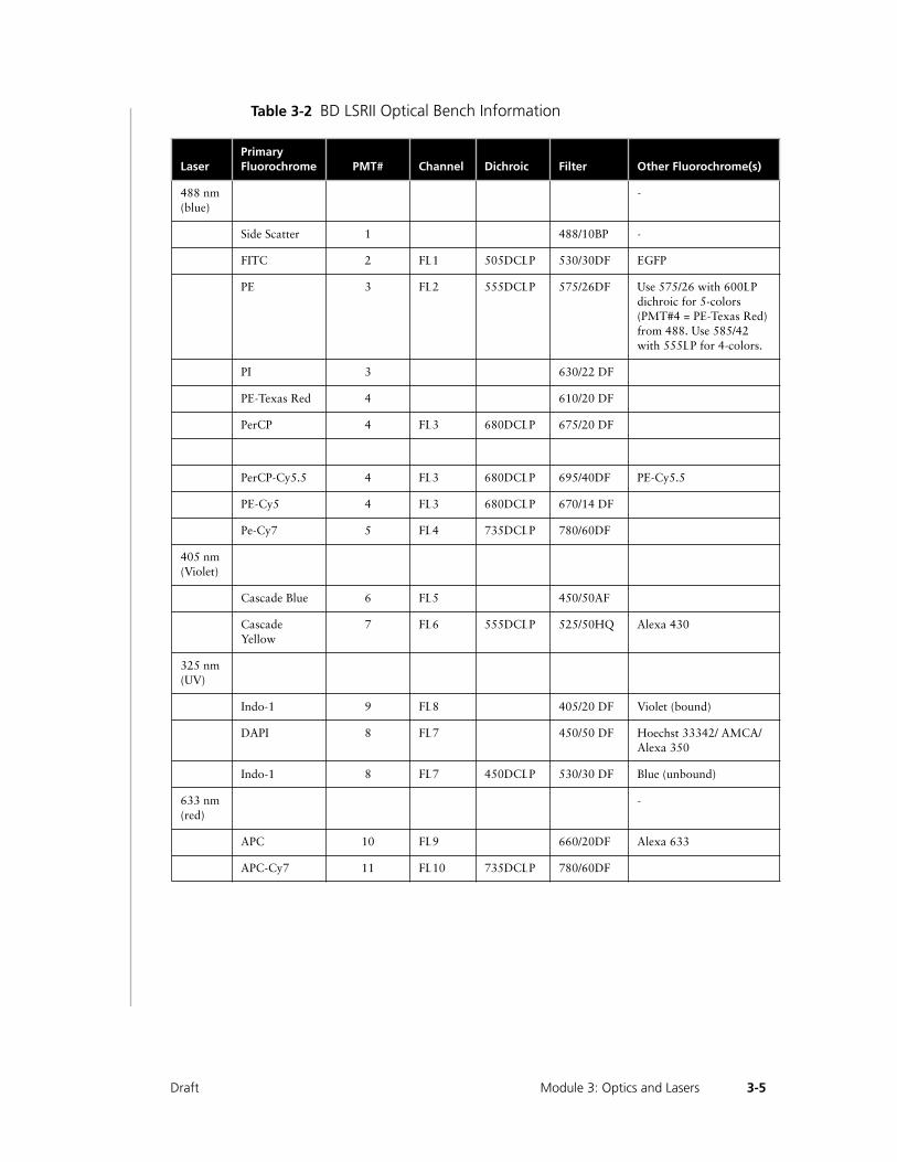
Table 3-2 BD LSRII Optical Bench Information
LaserPrimary Fluorochrome PMT# Channel Dichroic Filter Other Fluorochrome(s)
488 nm (blue)
-
Side Scatter 1 488/10BP -
FITC 2 FL1 505DCLP 530/30DF EGFP
PE 3 FL2 555DCLP 575/26DF Use 575/26 with 600LP dichroic for 5-colors (PMT#4 = PE-Texas Red) from 488. Use 585/42 with 555LP for 4-colors.
PI 3 630/22 DF
PE-Texas Red 4 610/20 DF
PerCP 4 FL3 680DCLP 675/20 DF
PerCP-Cy5.5 4 FL3 680DCLP 695/40DF PE-Cy5.5
PE-Cy5 4 FL3 680DCLP 670/14 DF
Pe-Cy7 5 FL4 735DCLP 780/60DF
405 nm (Violet)
Cascade Blue 6 FL5 450/50AF
Cascade Yellow
7 FL6 555DCLP 525/50HQ Alexa 430
325 nm (UV)
Indo-1 9 FL8 405/20 DF Violet (bound)
DAPI 8 FL7 450/50 DF Hoechst 33342/ AMCA/Alexa 350
Indo-1 8 FL7 450DCLP 530/30 DF Blue (unbound)
633 nm (red)
-
APC 10 FL9 660/20DF Alexa 633
APC-Cy7 11 FL10 735DCLP 780/60DF
3-5Draft Module 3: Optics and Lasers
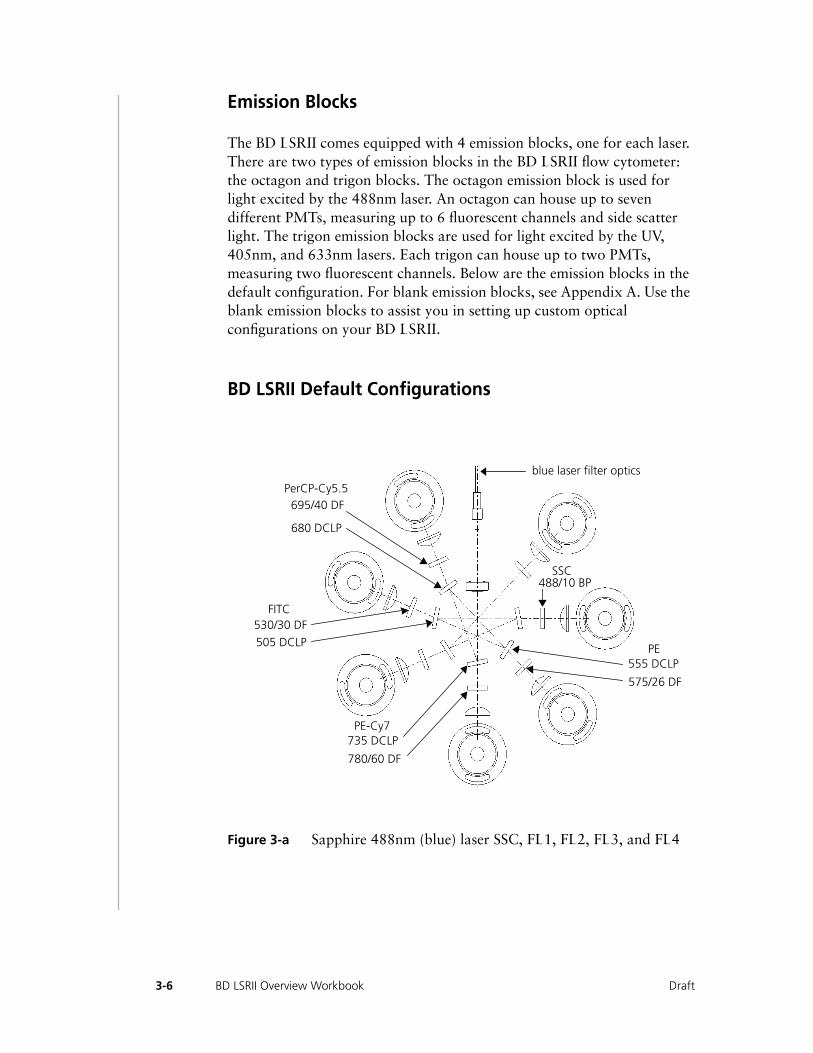
Emission Blocks
The BD LSRII comes equipped with 4 emission blocks, one for each laser. There are two types of emission blocks in the BD LSRII flow cytometer: the octagon and trigon blocks. The octagon emission block is used for light excited by the 488nm laser. An octagon can house up to seven different PMTs, measuring up to 6 fluorescent channels and side scatter light. The trigon emission blocks are used for light excited by the UV, 405nm, and 633nm lasers. Each trigon can house up to two PMTs, measuring two fluorescent channels. Below are the emission blocks in the default configuration. For blank emission blocks, see Appendix A. Use the blank emission blocks to assist you in setting up custom optical configurations on your BD LSRII.
BD LSRII Default Configurations
Figure 3-a Sapphire 488nm (blue) laser SSC, FL1, FL2, FL3, and FL4
blue laser filter optics
SSC488/10 BP
555 DCLPPE
575/26 DF
735 DCLPPE-Cy7
780/60 DF
530/30 DFFITC
505 DCLP
695/40 DFPerCP-Cy5.5
680 DCLP
3-6 BD LSRII Overview Workbook Draft
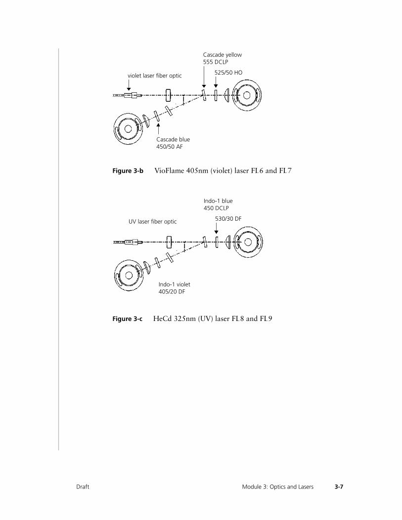
Figure 3-b VioFlame 405nm (violet) laser FL6 and FL7
Figure 3-c HeCd 325nm (UV) laser FL8 and FL9
violet laser fiber optic
Cascade blue450/50 AF
Cascade yellow555 DCLP
525/50 HO
UV laser fiber optic
Indo-1 blue450 DCLP
Indo-1 violet405/20 DF
530/30 DF
3-7Draft Module 3: Optics and Lasers
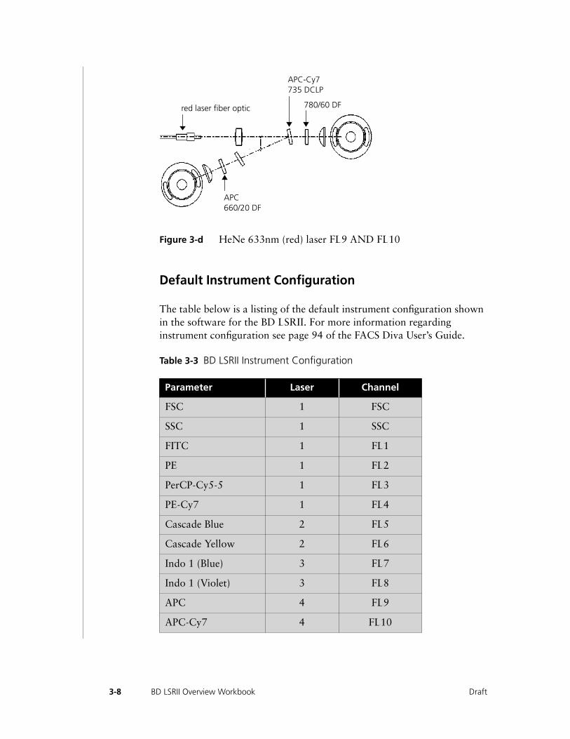
Figure 3-d HeNe 633nm (red) laser FL9 AND FL10
Default Instrument Configuration
The table below is a listing of the default instrument configuration shown in the software for the BD LSRII. For more information regarding instrument configuration see page 94 of the FACS Diva User’s Guide.
Table 3-3 BD LSRII Instrument Configuration
Parameter Laser Channel
FSC 1 FSC
SSC 1 SSC
FITC 1 FL1
PE 1 FL2
PerCP-Cy5-5 1 FL3
PE-Cy7 1 FL4
Cascade Blue 2 FL5
Cascade Yellow 2 FL6
Indo 1 (Blue) 3 FL7
Indo 1 (Violet) 3 FL8
APC 4 FL9
APC-Cy7 4 FL10
red laser fiber optic
APC-Cy7735 DCLP
APC660/20 DF
780/60 DF
3-8 BD LSRII Overview Workbook Draft

EGFP 1 FL1
EYFP 1 FL2
PE-Cy5 1 FL3
PE-Cy5-5 1 FL3
PerCP 1 FL3
ECFP 2 FL5
ß-Lactamase blue 2 FL5
Alexa 430 2 FL6
ECFP to EYFP FRET 2 FL6
ß-Lactamase green 2 FL6
Alexa 350 3 FL7
AMCA 3 FL7
Hoechst 33342 3 FL7
DAPI 3 FL7
Alexa 633 4 FL9
* The default Instrument Settings parameters are indicated by shading.
Parameter Laser Channel
3-9Draft Module 3: Optics and Lasers

BD LSRII Optics Exercise
Using Table 3-2 on page 3-5 enter the dichroic and bandpass filters you would use for the following fluorochromes.
Table 3-4 Optics exercise
Next, using the information in Table 3-4, enter the appropriate placement of the dichroic and bandpass filters on the Octagon in Figure 3-e. Remember to include SSC.
Figure 3-e Octagon
Fluorochrome Excitation Emission Dichroic Bandpass
EGFP 489nm 508nm
PE 480nm 578nm
PerCP 490nm 675nm
PE-Cy7 480nm 795nm
13
24
5
3-10 BD LSRII Overview Workbook Draft
Changing Optical Filters
Some applications require the changing of optical filters. For example, calcium-flux experiments with indo-1 use a different filter from that used in DNA experiments with DAPI or Hoechst 33342. Use the following procedure to change filters.
1 Lift the right lid of the instrument.
2 Remove the desired filter.
3 Replace it with the new filter.
4 Close the instrument lid.
NOTE: Make sure the label on the filter holder points away from the PMT, toward the laser light.
3-11Draft Module 3: Optics and Lasers

3-12 BD LSRII Overview Workbook Draft
Draft
4• • • • • • • • • • • • • • • • • • • • • • • • • • • • • • • • • • • • • • • • • • • • • • • • • • • • • • • • • • • •
Instrument Quality Control
After completing this module, you will be able to:
◆
Perform daily quality control on your BD LSRII

4-2
BD LSRII Overview Workbook Draft
Instrument Quality Control
Instrument quality control is a process that ensures consistent instrument performance on a daily basis given the same QC sample and instrument settings.
Daily instrument quality control consists of the following:
• copying instrument settings from a previous, similar setup
• running a QC sample (beads or prepared cells)
When instrument settings and the QC sample are kept constant, changes in the means and CVs indicate variations in instrument performance over time. Keep track of means and CVs in a quality control (QC) log. QC data should be analyzed for trends over the past 30–60 runs.
NOTE: NOTE: QC results are affected by laser and fluidics performance. BD Biosciences strongly recommends following the laser and fluidics maintenance procedures in the found in this workbook.
4-3Draft Module 4: Instrument Quality Control
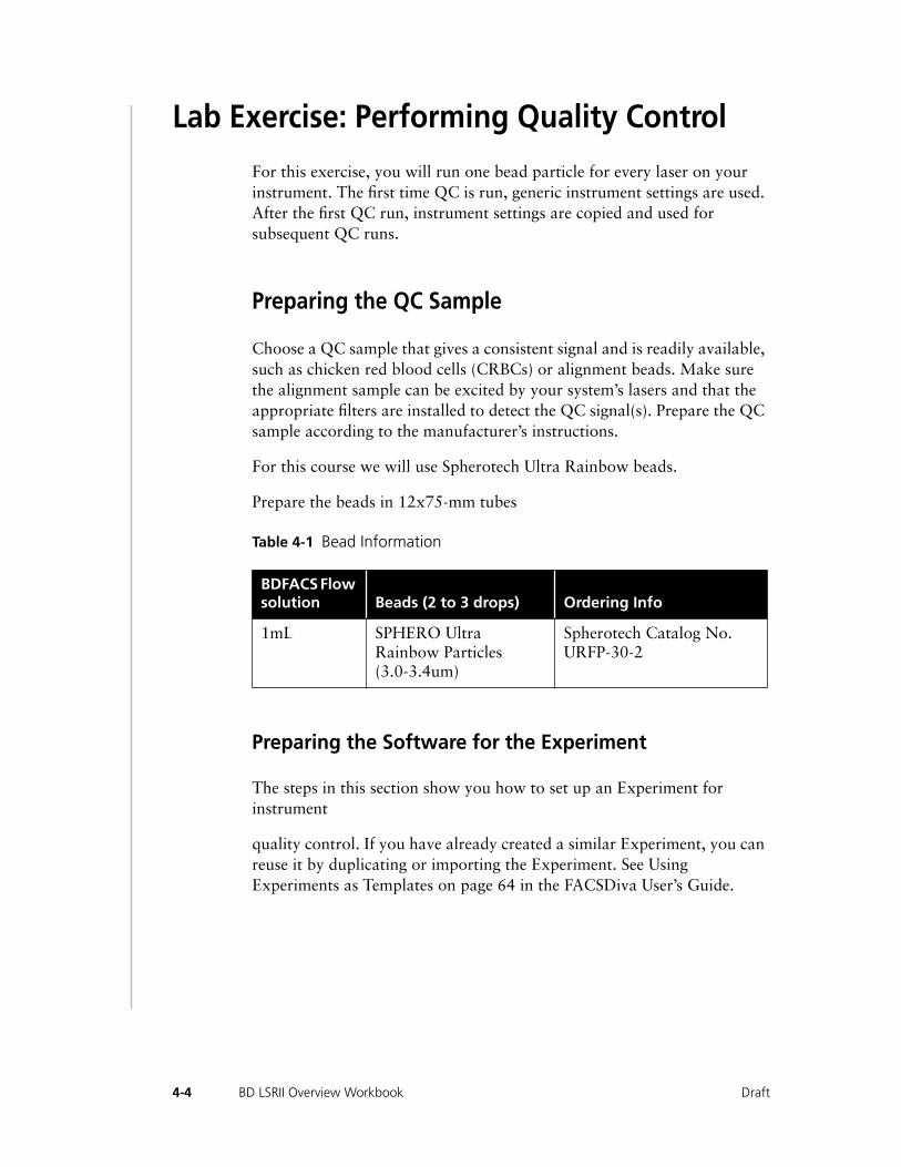
Lab Exercise: Performing Quality Control
For this exercise, you will run one bead particle for every laser on your instrument. The first time QC is run, generic instrument settings are used. After the first QC run, instrument settings are copied and used for subsequent QC runs.
Preparing the QC Sample
Choose a QC sample that gives a consistent signal and is readily available, such as chicken red blood cells (CRBCs) or alignment beads. Make sure the alignment sample can be excited by your system’s lasers and that the appropriate filters are installed to detect the QC signal(s). Prepare the QC sample according to the manufacturer’s instructions.
For this course we will use Spherotech Ultra Rainbow beads.
Prepare the beads in 12x75-mm tubes
Table 4-1 Bead Information
Preparing the Software for the Experiment
The steps in this section show you how to set up an Experiment for instrument
quality control. If you have already created a similar Experiment, you can reuse it by duplicating or importing the Experiment. See Using Experiments as Templates on page 64 in the FACSDiva User’s Guide.
BDFACS Flow solution Beads (2 to 3 drops) Ordering Info
1mL SPHERO Ultra Rainbow Particles (3.0-3.4um)
Spherotech Catalog No. URFP-30-2
4-4 BD LSRII Overview Workbook Draft

1 Choose Instrument > Instrument Configuration and verify the current configuration.
Make sure the configuration lists the parameters to be measured and that the channels correspond to the optical bench configuration.
m CAUTION: For accurate data results, the Instrument Configuration dialog box must reflect the physical layout of the BD LSRII optical bench.
If you need to add additional parameters or change the current configuration, see Instrument Configuration on page 94 in the FACSDiva User’s Guide.
2 Click the corresponding Workspace tools to display the Browser, Instrument Status, Inspector, Worksheet, and Acquisition Controls frames, as needed.
3 Optional) Press Ctrl-N to add a new folder to the Browser; rename the folder with your name.
Alternatively, you can name the folder Instrument QC or you can create an Instrument QC folder inside another folder. See Organizing Experiments on page 62 in the FACSDiva User’s Guide for ideas on how to organize Experiments.
4 Press Ctrl-E to create a new Experiment; rename the Experiment with an appropriate name.
For example, use the current month and year, Instrument QC, or the operator’s initials followed by an appropriate identifier.
NOTE: Tip: To place an Experiment inside a folder, select the folder before creating the Experiment.
5 Rename the new Specimen with today’s date; rename the first Tube Ultra beads.
This Tube will be used to QC the instrument for all the lasers at once.
4-5Draft Module 4: Instrument Quality Control
6 With the Ultra bead Tube selected in the Browser, click on the Instr. Settings >Parameters tab in the Inspector and delete any unnecessary parameters.
Tip Save space in the database by listing only appropriate parameters. For example, list only PerCP-Cy5.5 for the FL3 channel.
7 Deselect the Log checkboxes for all the parameters.
8 Name the worksheet with today’s date.
Click on the worksheet to display worksheet options in the Inspector. Change the name in the Name field.
NOTE: Tip You can later duplicate the Specimen for a subsequent quality control and keep the plots for each day on a separate worksheet.
9 Create the following plots for the Ultra beads Tube:
• FSC vs SSC dot plot
• FITC, PE, PerCP, PE-Cy7, APC, APC-Cy7, Alexa 430, Cascade Blue, Indo-1 blue, and Indo-1 violet (10 histograms total)
NOTE: Tip To duplicate a plot, hold down the Control key while dragging the plot to a new location. The plot is duplicated as it is dragged.
10 Right-click on each plot and choose Create Statistics View.
11 Set up the statistics view to display the mean and CV for appropriate fluorochrome for each plot.
Select the statistics view for the FITC plot, click on the Statistics tab in the Inspector, and add the CV and mean for only the FITC fluorochrome. Set the number of integers (#) to 1 for the CVs and 0 for the means. Repeat selecting statistics for each plot and
4-6 BD LSRII Overview Workbook Draft
fluorochrome. For more information, see Using the Statistics Inspector on page 135 in the FACSDiva User’s Guide.
12 In the Acquisition Controls frame, set the Number to Record to 10,000 evt. and the Events to Display to 500 evt.
NOTE: Tip Decreasing the number of displayed events will increase the data refresh rate.
13 13 Resize the plots and statistics views so that they will fit on two pages.
Place the 488 excited fluorochromes on the first page, and the remaining plots on the second page.
Preparing the Instrument for QC
1 Perform daily startup procedures, if needed.
Verify that the sheath tank is filled, the waste tank is empty, and that the system is free of bubbles.
2 Verify that the optical bench is configured correctly for QC.
The optical bench should be in the default configuration. See the table in the appendix for the default configuration.
Running the beads for QC
1 Install a sample tube containing beads for QC.
These particles are 3.0–3.4 µm in size and fluoresce in all channels when excited by the lasers.
2 Select MED on the fluid control panel, and press RUN.
3 Adjust the FSC voltage and SSC voltage to place the bead population on scale in the FSC vs SSC plot.
4-7Draft Module 4: Instrument Quality Control
4 Draw a gate around the singlet population.
5 Adjust the FITC voltage until the mean channel is at channel 200 ±5.
View the FITC histogram as you adjust the FITC voltage. Adjust the voltage until the population mean is at channel 200 ±5.
6 Repeat the adjustment of PMT voltages for all the other channels to place the mean at channel 200 ±5 in each parameter.
View the appropriate histogram as you adjust the voltages. Adjust the voltages until the population mean is at channel 200 ±5.
7 Select LO on the fluid control panel and set the sample fine adjust control knob to its midpoint.
Verify that the flow rate is approximately 100 to 150 events/sec. If needed, dilute the sample to obtain the flow rate.
Recording and Analyzing QC Results
1 Ctrl-Click the Acquisition pointer to begin recording.
Alternatively, click the Record button in the Acquisition Controls frame. You will collect 10,000 total events, as specified in the Acquisition Controls frame.
2 After recording is complete, draw an Interval gate around each peak on the fluorescence histograms.
3 Use the Population Hierarchy to rename each population defined by the Interval gates.
To display the Population Hierarchy view, right-click the plot and choose Show Population Hierarch. Select a population in the Hierarchy view and enter a new name to change it. For example, change P1 to FSC, P2 to SSC, and P3 to FITC.
4-8 BD LSRII Overview Workbook Draft
4 Edit the statistics view to show only the named populations.
Select the statistics view. Click on the Populations tab in the Statistics Inspector and delete the All Events population.
5 Copy the results into the QC log and print the worksheet for your records.
Keep a record of the daily QC results for future reference. By comparing results from day to day you will be able to monitor daily instrument performance.
Reusing the Experiment
The first time you perform instrument QC, you created a new worksheet, subsequent QC runs can use the same worksheet.
To reuse this Experiment, do the following.
1 Open the instrument optimization Experiment.
2 Create a new worksheet.
3 Right-click the Specimen and choose Duplicate without Data.
The QC Tube appears under the new Specimen; empty plots and statistics views appear on the new worksheet. The instrument settings will copy with the specimen.
4 Rename the Specimen and the worksheet.
5 Double-click the Ultra beads Tube to locate the plots.
6 Continue QC.
4-9Draft Module 4: Instrument Quality Control

4-10 BD LSRII Overview Workbook Draft

Appendix A• • • • • • • • • • • • • • • • • • • • • • • • • • • • • • • • • • • • • • • • • • • • • • • • • • • • • • • • • • • •
Worksheets
Draft

A-2 BD LSRII Overview Workbook Draft
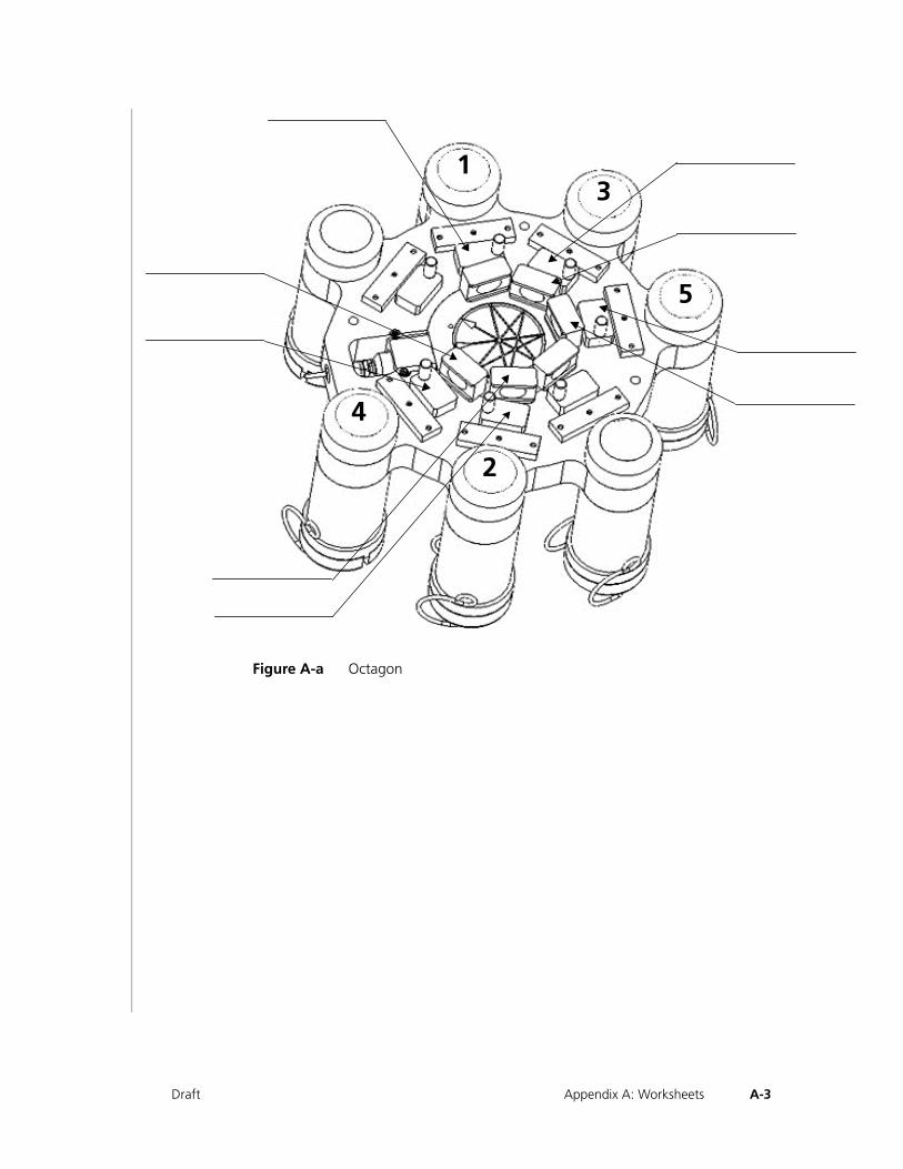
Figure A-a Octagon
13
2
4
5
A-3Draft Appendix A: Worksheets
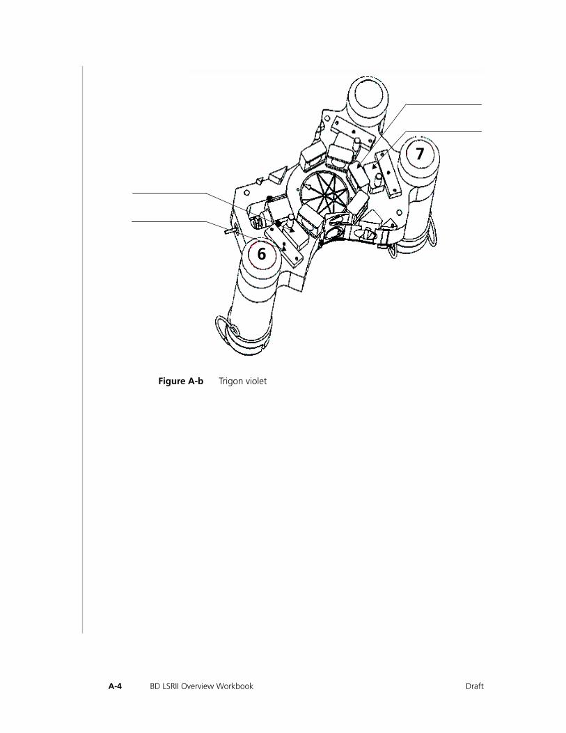
Figure A-b Trigon violet
7
6
A-4 BD LSRII Overview Workbook Draft
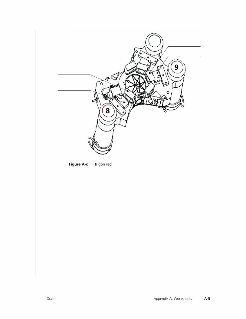
Figure A-c Trigon red
9
8
A-5Draft Appendix A: Worksheets
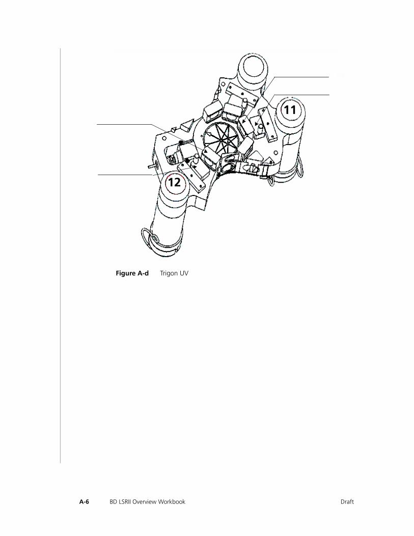
Figure A-d Trigon UV
11
12
A-6 BD LSRII Overview Workbook Draft

Appendix B• • • • • • • • • • • • • • • • • • • • • • • • • • • • • • • • • • • • • • • • • • • • • • • • • • • • • • • • • • • •
Troubleshooting
Draft

B-2 BD LSRII Overview Workbook Draft
The tips in this section are designed to help you troubleshoot your experiments. If additional assistance is required, contact Technical Support or your local BD Biosciences service representative. When contacting BD Biosciences, please have the following information handy:
• product name, part number, and serial number
• any error messages
• details of recent instrument performance
In the US, call (800) 448-BDIS (2347), Option 1.
In Canada, call (800) 268-5430.
In other countries, contact your local BD Biosciences representative. Refer to our website, http://www.bdfacs.com, for up-to-date contact information.
B-3Draft Appendix B: Troubleshooting
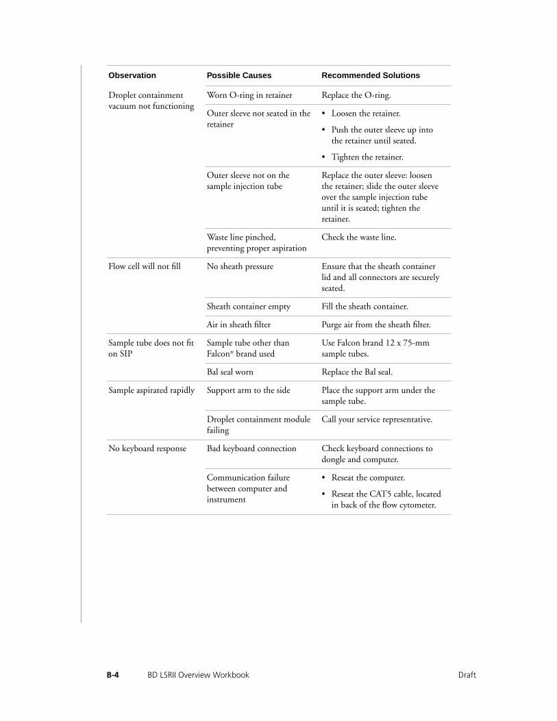
Obser vation Possib le Causes Recommended Solutions
Droplet containment vacuum not functioning
Worn O-ring in retainer Replace the O-ring.
Outer sleeve not seated in the retainer
• Loosen the retainer.
• Push the outer sleeve up into the retainer until seated.
• Tighten the retainer.
Outer sleeve not on the sample injection tube
Replace the outer sleeve: loosen the retainer; slide the outer sleeve over the sample injection tube until it is seated; tighten the retainer.
Waste line pinched, preventing proper aspiration
Check the waste line.
Flow cell will not fill No sheath pressure Ensure that the sheath container lid and all connectors are securely seated.
Sheath container empty Fill the sheath container.
Air in sheath filter Purge air from the sheath filter.
Sample tube does not fit on SIP
Sample tube other than Falcon® brand used
Use Falcon brand 12 x 75-mm sample tubes.
Bal seal worn Replace the Bal seal.
Sample aspirated rapidly Support arm to the side Place the support arm under the sample tube.
Droplet containment module failing
Call your service representative.
No keyboard response Bad keyboard connection Check keyboard connections to dongle and computer.
Communication failure between computer and instrument
• Reseat the computer.
• Reseat the CAT5 cable, located in back of the flow cytometer.
B-4 BD LSRII Overview Workbook Draft
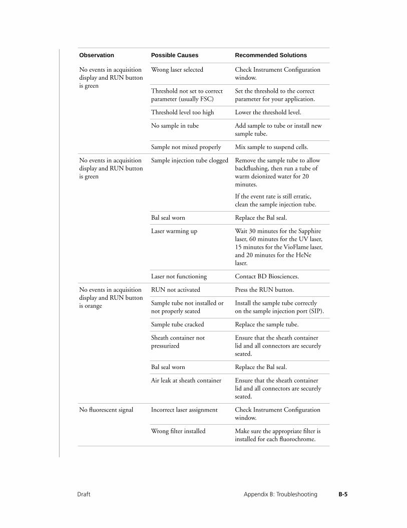
No events in acquisition display and RUN button is green
Wrong laser selected Check Instrument Configuration window.
Threshold not set to correct parameter (usually FSC)
Set the threshold to the correct parameter for your application.
Threshold level too high Lower the threshold level.
No sample in tube Add sample to tube or install new sample tube.
Sample not mixed properly Mix sample to suspend cells.
No events in acquisition display and RUN button is green
Sample injection tube clogged Remove the sample tube to allow backflushing, then run a tube of warm deionized water for 20 minutes.
If the event rate is still erratic, clean the sample injection tube.
Bal seal worn Replace the Bal seal.
Laser warming up Wait 30 minutes for the Sapphire laser, 60 minutes for the UV laser, 15 minutes for the VioFlame laser, and 20 minutes for the HeNe laser.
Laser not functioning Contact BD Biosciences.
No events in acquisition display and RUN button is orange
RUN not activated Press the RUN button.
Sample tube not installed or not properly seated
Install the sample tube correctly on the sample injection port (SIP).
Sample tube cracked Replace the sample tube.
Sheath container not pressurized
Ensure that the sheath container lid and all connectors are securely seated.
Bal seal worn Replace the Bal seal.
Air leak at sheath container Ensure that the sheath container lid and all connectors are securely seated.
No fluorescent signal Incorrect laser assignment Check Instrument Configuration window.
Wrong filter installed Make sure the appropriate filter is installed for each fluorochrome.
Obser vation Possib le Causes Recommended Solutions
B-5Draft Appendix B: Troubleshooting
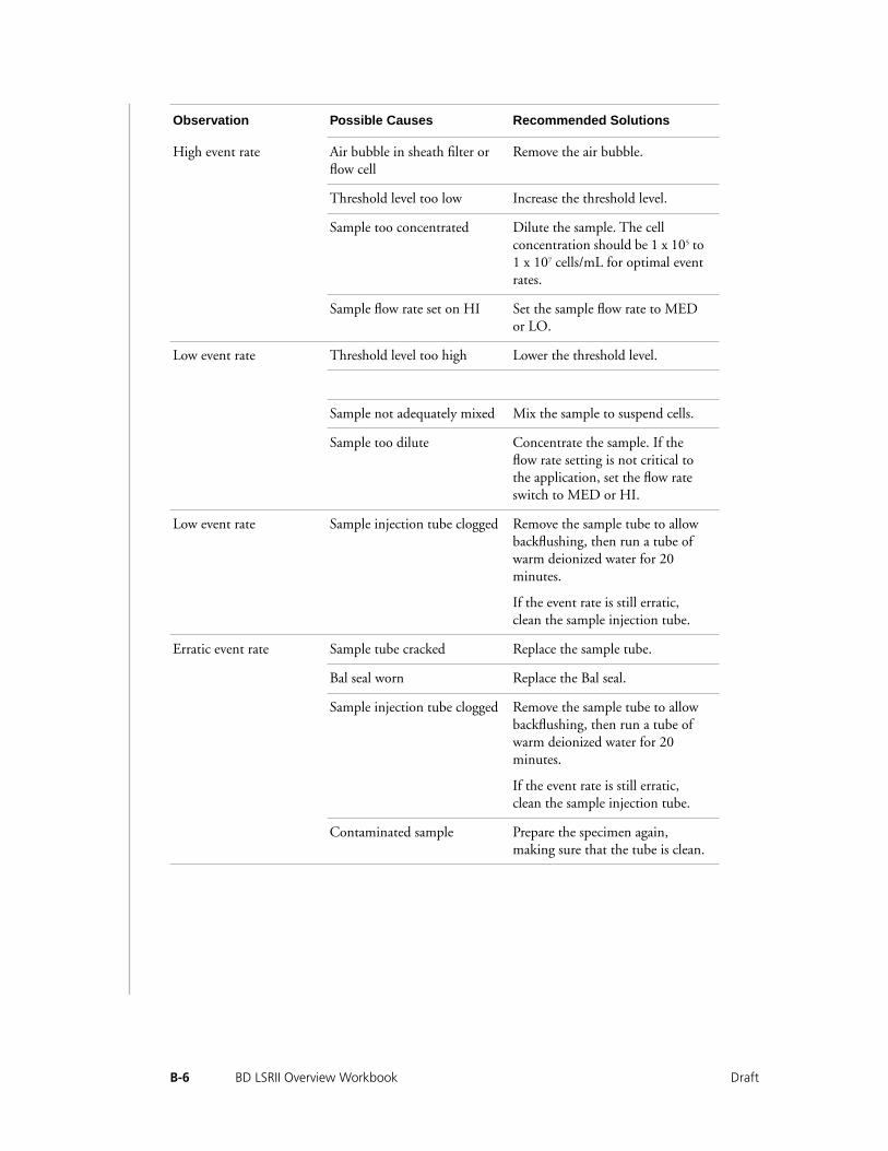
High event rate Air bubble in sheath filter or flow cell
Remove the air bubble.
Threshold level too low Increase the threshold level.
Sample too concentrated Dilute the sample. The cell concentration should be 1 x 10⁵ to 1 x 10⁷ cells/mL for optimal event rates.
Sample flow rate set on HI Set the sample flow rate to MED or LO.
Low event rate Threshold level too high Lower the threshold level.
Sample not adequately mixed Mix the sample to suspend cells.
Sample too dilute Concentrate the sample. If the flow rate setting is not critical to the application, set the flow rate switch to MED or HI.
Low event rate Sample injection tube clogged Remove the sample tube to allow backflushing, then run a tube of warm deionized water for 20 minutes.
If the event rate is still erratic, clean the sample injection tube.
Erratic event rate Sample tube cracked Replace the sample tube.
Bal seal worn Replace the Bal seal.
Sample injection tube clogged Remove the sample tube to allow backflushing, then run a tube of warm deionized water for 20 minutes.
If the event rate is still erratic, clean the sample injection tube.
Contaminated sample Prepare the specimen again, making sure that the tube is clean.
Obser vation Possib le Causes Recommended Solutions
B-6 BD LSRII Overview Workbook Draft

Scatter parameters appear distorted
Instrument settings maladjusted
Optimize the scatter parameters.
Air bubble in sheath filter or flow cell
Remove the air bubble.
Flow cell dirty Perform the system flush procedure.
Air leak at sheath container Ensure that the sheath container lid is tight and all connectors are secure.
Hypertonic buffers or fixative Replace the buffers and fixative.
Excessive amount of debris appearing in display
Threshold level too low Increase the threshold level.
Sheath filter dirty Change the sheath filter.
Flow cell dirty Perform the system flush procedure.
Sample contains excessive amount of debris
Examine the sample under a microscope.
Stock sheath fluid contaminated
Rinse the sheath container with deionized water, then fill with sheath fluid from another (or new lot) bulk container.
High CV Air bubble in sheath filter or flow cell
Remove the air bubble.
Sample flow rate set too high Set the sample flow rate lower.
Air leak at sheath container Ensure that the sheath container lid is tight and all connectors are secure.
Flow cell dirty Perform the system flush procedure.
Poor sample preparation Repeat sample preparation.
Sample not diluted in same fluid as sheath fluid
Dilute the sample in the same fluid as you are using for sheath.
Old or contaminated quality control (QC) particles
Make new QC samples and perform the quality control procedure again.
Obser vation Possib le Causes Recommended Solutions
B-7Draft Appendix B: Troubleshooting
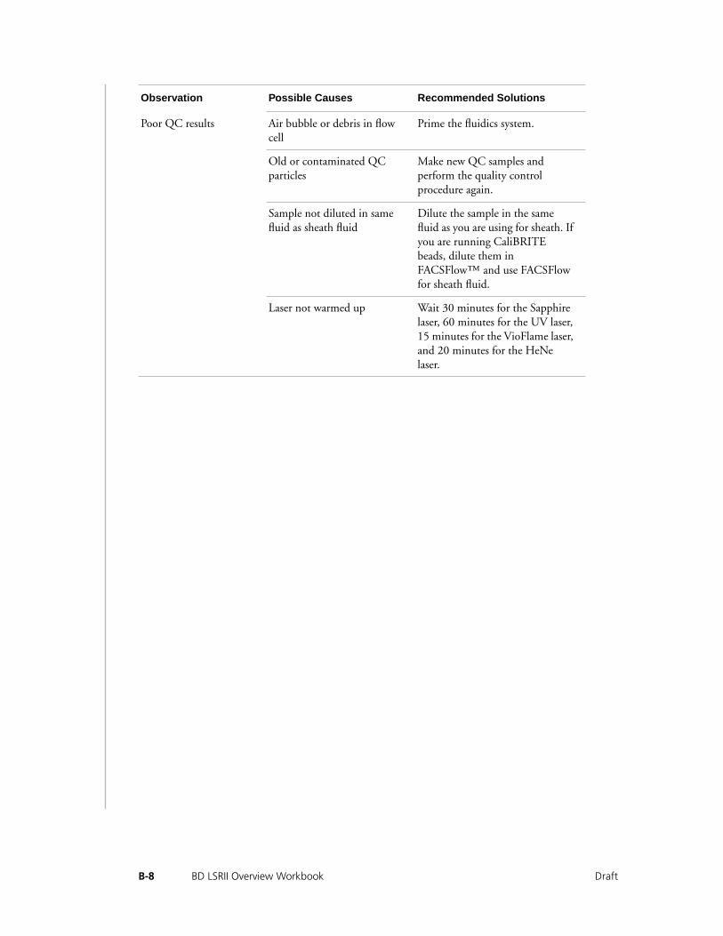
Poor QC results Air bubble or debris in flow cell
Prime the fluidics system.
Old or contaminated QC particles
Make new QC samples and perform the quality control procedure again.
Sample not diluted in same fluid as sheath fluid
Dilute the sample in the same fluid as you are using for sheath. If you are running CaliBRITE beads, dilute them in FACSFlow™ and use FACSFlow for sheath fluid.
Laser not warmed up Wait 30 minutes for the Sapphire laser, 60 minutes for the UV laser, 15 minutes for the VioFlame laser, and 20 minutes for the HeNe laser.
Obser vation Possib le Causes Recommended Solutions
B-8 BD LSRII Overview Workbook Draft

B-9Draft Appendix B: Troubleshooting

B-10 BD LSRII Overview Workbook Draft
BD LSR Overview
• • • • • • • • • • • • • • • • • • • • • • • • • • • • • • • • • • • • • • • • • • • • • • • • • • • • • • • •
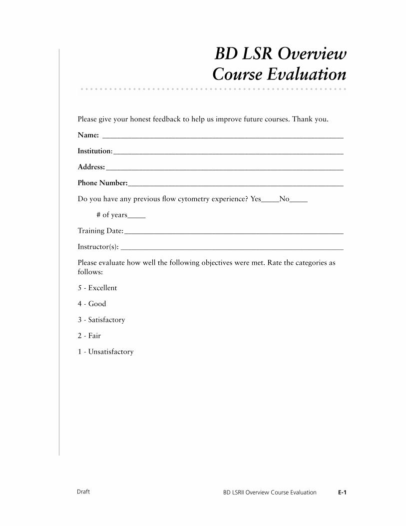
Course Evaluation
Please give your honest feedback to help us improve future courses. Thank you.
Name: __________________________________________________________________
Institution:_______________________________________________________________
Address: _________________________________________________________________
Phone Number:___________________________________________________________
Do you have any previous flow cytometry experience? Yes_____No_____
# of years_____
Training Date:____________________________________________________________
Instructor(s): _____________________________________________________________
Please evaluate how well the following objectives were met. Rate the categories as follows:
5 - Excellent
4 - Good
3 - Satisfactory
2 - Fair
1 - Unsatisfactory
E-1BD LSRII Overview Course EvaluationDraft
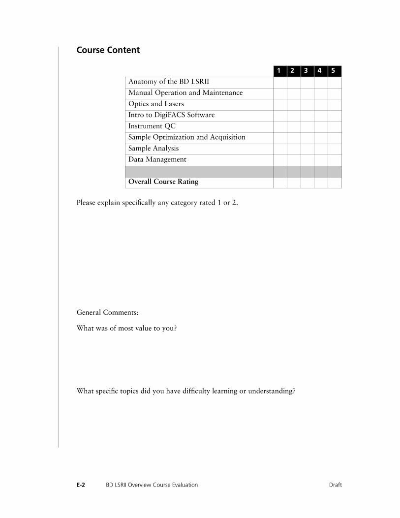
Course Content
Please explain specifically any category rated 1 or 2.
General Comments:
What was of most value to you?
What specific topics did you have difficulty learning or understanding?
1 2 3 4 5
Anatomy of the BD LSRII
Manual Operation and Maintenance
Optics and Lasers
Intro to DigiFACS Software
Instrument QC
Sample Optimization and Acquisition
Sample Analysis
Data Management
Overall Course Rating
E-2 BD LSRII Overview Course Evaluation Draft

Did the course meet your expectations?
E-3BD LSRII Overview Course EvaluationDraft

E-4 BD LSRII Overview Course Evaluation Draft


![l>lf·· E ·B; -I,:,C-·-1·1V · cat. no.i bd lj.657 bd lj.6]5 bd 4630 bd 4·627 bd 4628 bd 4886 bd 4546 bd 4·545 bd 4544 bd 4542 bd lj,588 bd lj.593 bd 0102 bd 4636 bd 4632 bd](https://static.fdocuments.in/doc/165x107/5f7c69bb7d840d18665ab1e6/llf-e-b-ic-11v-cat-noi-bd-lj657-bd-lj65-bd-4630-bd-4627-bd-4628-bd.jpg)