BD 74 00 Foundations
49
May 2000 DESIGN MANUAL FOR ROADS AND BRIDGES VOLUME 2 HIGHWAY STRUCTURES: DESIGN (SUBSTRUCTURES, SPECIAL STRUCTURES AND MATERIALS) SECTION 1 SUBSTRUCTURES PART 8 BD 74/00 FOUNDATIONS SUMMARY This Standard implements BS 8004: 1986 Code of Practice for Foundations. It gives guidance on lateral loading of piles by incorporating and superseding BD 32/88 and BA 25/88. It states the requirements for reinforcement of bored cast-in-place foundation piles. INSTRUCTIONS FOR USE 1. Remove existing contents pages for Volume 2. 2. Insert new contents pages for Volume 2, dated May 2000. 3. Insert BD 74 into Volume 2, Section 1. 4. Archive this sheet as appropriate. Note: A quarterly index with a full set of Volume Contents Pages is available separately from The Stationery Office Ltd.
-
Upload
shawn-mckenzie -
Category
Documents
-
view
471 -
download
74
Transcript of BD 74 00 Foundations
May 2000
DESIGN MANUAL FOR ROADS AND BRIDGES
VOLUME 2 HIGHWAY STRUCTURES:DESIGN(SUBSTRUCTURES,SPECIAL STRUCTURESAND MATERIALS)
SECTION 1 SUBSTRUCTURES
PART 8
BD 74/00
FOUNDATIONS
SUMMARY
This Standard implements BS 8004: 1986 Code ofPractice for Foundations. It gives guidance on lateralloading of piles by incorporating and supersedingBD 32/88 and BA 25/88. It states the requirements forreinforcement of bored cast-in-place foundation piles.
INSTRUCTIONS FOR USE
1. Remove existing contents pages for Volume 2.
2. Insert new contents pages for Volume 2, datedMay 2000.
3. Insert BD 74 into Volume 2, Section 1.
4. Archive this sheet as appropriate.
Note: A quarterly index with a full set of VolumeContents Pages is available separately from TheStationery Office Ltd.

BD 74/00
Foundations
DESIGN MANUAL FOR ROADS AND BRIDGES
Summary: This Standard implements BS 8004: 1986 Code of Practice forFoundations. It gives guidance on lateral loading of piles by incorporatingand superseding BD 32/88 and BA 25/88. It states the requirements forreinforcement of bored cast-in-place foundation piles.
* A Government Department in Northern Ireland
THE HIGHWAYS AGENCY
THE SCOTTISH EXECUTIVE DEVELOPMENTDEPARTMENT
THE NATIONAL ASSEMBLY FOR WALESCYNULLIAD CENEDLAETHOL CYMRU
THE DEPARTMENT FOR REGIONAL DEVELOPMENT*!!!!!

Volume 2 Section 1Part 8 BD 74/00
May 2000
REGISTRATION OF AMENDMENTS
Amend Page No Signature & Date of Amend Page No Signature & Date ofNo incorporation of No incorporation of
amendments amendments
Registration of Amendments

Volume 2 Section 1Part 8 BD 74/00
May 2000
REGISTRATION OF AMENDMENTS
Amend Page No Signature & Date of Amend Page No Signature & Date ofNo incorporation of No incorporation of
amendments amendments
Registration of Amendments

VOLUME 2 HIGHWAY STRUCTURES:DESIGN(SUBSTRUCTURES,SPECIAL STRUCTURESAND MATERIALS)
SECTION 1 SUBSTRUCTURES
PART 8
BD 74/00
FOUNDATIONS
Contents
Chapter
1. Introduction
2. Use of British Standard BS 8004: 1986
3. References
4. Enquiries
Annex A Amendments to BS 8004: 1986
Annex B Guidance on Lateral Loading of Piles
Annex C The Reinforcement of Bored Cast-in-PlaceEmbedded Foundation Piles
DESIGN MANUAL FOR ROADS AND BRIDGES
May 2000

Volume 2 Section 1Part 8 BD 74/00
Chapter 1Introduction
1. INTRODUCTION
General
1.1 The purpose of this Standard is to implement BS8004: 1986 Code of practice for Foundations.
1.2 This Standard incorporates and supersedes BD32/88 and BA 25/88. It gives guidance on lateral loadingof piles and states the requirements for reinforcement ofbored cast-in-place foundation piles. Considerableadvances in computing power and program capabilityhave taken place since BA 25/88. The usefulness ofcurrent computer programs is reviewed in publicationssuch as Ground Engineering and the reader is directed tothese.
Equivalence
1.3 The construction of foundations willnormally be carried out under contractsincorporating the Specification for Highway Works(MCHW 1). In such cases, products conforming toequivalent standards or technical specifications ofother member states of the European EconomicArea, and tests undertaken in other states of theEuropean Economic Area will be acceptable inaccordance with Clauses 104 and 105 of Series 100of that Specification. Any contract not containingthese clauses must contain suitable clauses ofmutual recognition having the same effect regardingwhich advice should be sought.
Scope
1.4 This Standard covers the use of BS 8004:1986 Code of practice for Foundations for allpermanent highway structures. This Standard givesguidance on lateral loading of piles and states therequirements for reinforcement of bored cast-in-place foundation piles. It sets out the OverseeingOrganisation’s particular requirements where thesediffer from, or are more comprehensive than, thosegiven in the British Standard.
I
M
1rhrec
May 2000
mplementation
1.5 This Standard should be used forthwith onall schemes for the construction and improvementof trunk roads, including motorways, currentlybeing prepared, provided that, in the opinion of theOverseeing Organisation, this would not result insignificant additional expense or delay. DesignOrganisations should confirm its application toparticular schemes with the OverseeingOrganisation. Where contract documents are basedon the Specification for Highway Works (MCHW1)use of this Standard is mandatory. For use inNorthern Ireland, this Standard will be applicableto those roads designated by the OverseeingOrganisation.
andatory Requirements
.6 Sections of the document which form mandatoryequirements of the Overseeing Organisation areighlighted by being contained within boxes. Theemainder of the document contains advice andnlargement which is commended to designers for theironsideration.
1/1

Volume 2 Section 1Part 8 BD 74/00
Chapter 2Use of the British Standard BS 8004: 1986
2. USE OF THE BRITISH STANDARD BS 8004: 1986
General
2.1 The design of foundations for all permanenthighway structures which are the responsibility ofthe Overseeing Organisation shall be carried out inaccordance with BS 8004: 1986 as amended by thisStandard. Where reference is made to any BritishStandard, this shall be taken as reference to thatPart as implemented by the OverseeingOrganisation.
2.2 The assessment of existing bridgefoundations should be carried out in accordancewith BD 44, the Assessment of Concrete HighwayBridges and Structures (DMRB 3.4), and BA 55,the Assessment of Bridge Substructures andFoundations, Retaining Walls and BuriedStructures (DMRB 3.4).
2.3 The amendments to BS 8004: 1986, whichare necessary to meet the Overseeing Organisation’srequirements, are given in Annex A to thisStandard. The amendments are listed under therelevant clause numbers of BS 8004: 1986.
These amendments include repeated references toDMRB Standards to replace British Standardswhich are not implemented by the OverseeingOrganisation. Should there be any conflict betweenthe clauses in BS 8004 or the amendments in AnnexA, and the appropriate clauses in DMRBStandards, the latter shall take precedence.However, examples not necessarily relevant to thedesign of foundations for highway structures havebeen retained in order to illustrate technical points.
Advice on temporary works has been retainedwhere these may have an effect on the design of thepermanent structure.
2.4 The reasons for the amendments are listed below:
i) existing clauses not relevant to permanenthighway structures
ii) reference to and consistency with the DMRBStandards
ii
iv
28bpdlilo
A
May 2000
i) revisions to out of date practices and references,and the introduction of recent Health & SafetyLegislation
) provision of additional advice
(a) “observational method”
(b) settlement considerations
(c) soil structure interaction
(d) pile testing
(e) reinforcement in piles
.5 This Standard retains the design principles of BS004 with its total factor of safety on the ultimateearing capacity to evaluate an allowable bearingressure or load. This is different from other DMRBocuments covering structural design which adopt amit state approach with partial factors applied to bothading and materials.
dditional Requirements
2.6 The clauses in BS 8004: 1986 that areexpressed in the form of recommendations using theword “should” are to be considered as mandatory.
2.7 Where reference is made to the “life” of thestructure, this shall be taken to mean the “designlife” which is defined in BS 5400: Part 1 asimplemented by BD 15 (DMRB 1.3). The designlife for these structures shall be 120 years.
2.8 Both long and short term ground and loadingconditions shall be considered so that the finaldesign satisfies the most onerous requirementsencountered during both the construction period andservice life of the structure.
2.9 Where reference is made to MCHW 1(Specification for Highway Works), this should beread as also referring to MCHW 2 (Notes forGuidance on the Specification for Highway Works).
2/1

Volume 2 Section 1Part 8 BD 74/00
Chapter 2Use of the British Standard BS 8004: 1986
Guidance on lateral loading of piles
2.10 Guidance on lateral loading of piles is given inAnnex B. This supersedes BD 32/88 and BA 25/88 andsupplements information given in BS 8004: 1986.
Reinforcement of bored cast-in-place embeddedfoundation piles
2.11 The requirements for reinforcement of boredcast-in-place foundation piles are stated in AnnexC. These supersede BS 8004:1986.
May 20002/2

Volume 2 Section 1Part 8 BD 74/00
Chapter 3References
3. REFERENCES
The following documents are referred to in thisStandard.
3.1. BSI publications.
BS 144: 1990 Wood preservation using coal tarcreosotes.
BS 5400: Part 1: 1988 General Statement.
BS 5400: Part 3: 1982 Code of Practice for Design ofSteel Bridges.
BS 5400: Part 4: 1990 Code of Practice for Design ofConcrete Bridges.
BS 5628: Code of Practice for use of Masonry.
BS 7361: Cathodic Protection, Part 1: 1991 Code ofPractice for Land and Marine Applications.
BS 7375: 1991 Code of Practice for Distribution ofElectricity on Construction and Building Sites.
BS 8002: 1994 Code of Practice for Earth RetainingStructures.
BS 8004: 1986 Code of Practice for Foundations.
BS 8006: 1995 Code of Practice for Strengthened/Reinforced Soils and Other Fills.
BS 8081: 1989 Code of Practice for GroundAnchorages.
BS 8102: 1990 Code of Practice for Protection ofStructures against Water from the Ground.
3.2. Design Manual for Roads and Bridges. TheStationery Office
BA 25 Piled Foundations (DMRB 2.1).
BA 55 The Assessment of Bridge Substructures andFoundations, Retaining Walls and BuriedStructures (DMRB 3.4.9).
BA 59 Design of Highway Bridges for Hydraulic
BA
BD
BD
BD
BD
BD
BD
BD
BD
BD
BD
BD
BD
HA
HA
3.3W
Vo
Vo
May 2000
Action (DMRB 1.3).
80 Use of Rock Bolts (DMRB 2.1.7).
10 Design of Highway Structures in Areas ofMining Subsidence (DMRB 1.3).
13 Design of Steel Bridges. Use of BS 5400:Part 3: 1982 (DMRB 1.3).
15 General Principles for the Design andConstruction of Bridges. Use of BS 5400:Part 1: 1988 (DMRB 1.3).
20 Bridge Bearings. Use of BS 5400: Part 9:1983 (DMRB 2.3).
24 The Design of Concrete Highway Bridges andStructures. Use of BS 5400: Part 4: 1990(DMRB 1.3).
32 Piled Foundations (DMRB 2.1).
37 Loads for Highway Bridges (DMRB 1.3).
41 Reinforced Clay Brickwork Retaining Walls ofPocket Type and Grouted - Cavity TypeConstruction (DMRB 2.1.1).
42 Design of Embedded Retaining Walls andBridge (DMRB 2.1.2).
44 The Assessment of Concrete Highway Bridgesand Structures (DMRB 3.4).
57 Design for Durability (DMRB 1.3.7).
60 Design of Highway Bridges for VehicleCollision Loads (DMRB 1.3).
34 Ground Investigation Procedure (DMRB 4.1).
75 Trunk Roads and Archaelogical Mitigation(DMRB 10.6.1)
Manual of Contract Documents for Highwayorks. The Stationery Office
lume 1 Specification for Highway Works (MCHW 1)
lume 2 Notes for Guidance on the Specification forHighway Works (MCHW 2).
3/1

Volume 2 Section 1Part 8 BD 74/00
May 2000 4/1
4. ENQUIRIES
All technical enquiries or comments on this Standard should be sent in writing as appropriate to:
Quality Services DirectorThe Highways AgencySt Christopher HouseSouthwark Street J KERMANLondon SE1 0TE Quality Services Director
Director, Road Network Management andMaintenance DivisionThe Scottish Executive Development DepartmentNational Roads Directorate N B MACKENZIEVictoria Quay Director, Road Network Management andEdinburgh EH6 6QQ Maintenance Division
The Chief Highway EngineerThe National Assembly for WalesCynulliad Cenedlaethol CymruCrown BuildingsCathays Park J R REESCardiff CF1 3NQ Chief Highway Engineer
Director of EngineeringDepartment for Regional DevelopmentRoads ServiceClarence Court10-18 Adelaide Street V CRAWFORDBelfast BT2 8GB Director of Engineering
Chapter 4Enquiries
Volume 2 Section 1Part 8 BD 74/00
ANNEX A. AMENDMENTS TO BS 8004: 1986 CODEOF PRACTICE FOR FOUNDATIONS
Annex A
The use of this annex is mandatory.
The following Clause titles are amended:
7.6 Integrity testing of cast-in-place pilesDelete title and replace with: “Non-destructive testingof piles”.Insert the following:7.6.1 Integrity testing7.6.2 Dynamic pile testing
The following Tables are not implemented:
13 Curing periods for use in the absence of controlcubes or steam curing
14 Suggested slump details for typical concretingsituations for cast-in-place piles
16 Resistivity and redox potential values17 Concrete exposed to sulphate attack
Section one. General1.1 ScopeDelete Note 1 and Note 2
1.2.41 factor of safety.Lines 2, 3 delete “or the ratio of the ultimate load to theapplied load”
At the end of Section 1.2, add the following clauses:
1.2.124 nominal loads. Where adequate statistical dataare available nominal loads are those appropriate to areturn period of 120 years. In the absence of such data,values that are considered to approximate to a 120 yearreturn period are given in BD 37 (DMRB 1.3).
Nominal loads shall be used as design loads.
1.2.125 dead loads. The permanent loads defined inBD 37 (DMRB 1.3), being dead loads of the structureand foundation, superimposed dead loads and loads dueto filling material above the foundation.
1.2.126 live loads. The transient loads defined in BD 37(DMRB 1.3) excluding wind loads which are consideredseparately.
2iApga“dfc(s(aaw(raaistst(wb
FbOaCles
2sL
2Pt
May 2000
.1.2.2 The foundation and the ground as annterrelated system.t end of last paragraph, add the following newaragraph: “Where prediction of the behaviour of theround and foundation is particularly difficult, it may beppropriate to adopt the approach known as theobservational method” in which the design is revieweduring construction. When this approach is used, theollowing requirements should be met beforeonstruction commences:a) the limits of behaviour which are acceptablehould be established;b) the range of possible behaviour should bessessed and it should be shown that there is ancceptable probability that the actual behaviour will beithin the acceptable limits;
c) a plan of monitoring should be devised which willeveal whether the actual behaviour lies within thecceptable limits. The monitoring should make this cleart a sufficiently early stage, and with sufficiently shortntervals to allow contingency actions to be undertakenuccessfully. The response time of the instruments andhe procedures for analysing the results should beufficiently rapid in relation to the possible evolution ofhe system;d) a plan of contingency actions should be devisedhich may be adopted if the monitoring revealsehaviour outside acceptable limits.
urther information on the “observational method” maye found in CIRIA Report 185 (1998) “Thebservational Method in ground engineering: principles
nd applications” by Nicholson D., Tse C-M. and Penny. and in TRL Report 228 (1996) “Movement trigger
imits when applying the Observational Method tombedded retaining wall construction on highwaychemes” by Card G.B. and Carder D.R.”
.1.2.3.2.3 Effect of adjacent cuttings, excavations orloping ground.ine 2, after “excavations” insert: “, retaining walls”
.1.2.3.3 Settlement.aragraph 1, after end of last sentence insert: “although
hese soils can also undergo creep”
A/1

Volume 2 Section 1Part 8 BD 74/00
Annex A
2.1.2.4 Movements independent of applied foundationload.(e) Line 1, after “internal erosion” insert: “due to pipingor washing out of fines”(f) Line 2, after “excavations” insert: “(including futureexcavations for services)”
2.1.3.1Line 6, replace “CP 102” with: “BS 8102”
2.2.1 Ground exploration and tests2.2.1.1 General.Paragraph 2 Line 2, after “BS 5930” insert: “andappropriate Procedures, including HA 34 (DMRB4.1).”
2.2.2 Allowable bearing pressure on various types ofground2.2.2.1 General.Paragraph 1, after last sentence add: “Foundations aresized using the loading combinations given in BD 37(DMRB 1.3) with load factors set to unity (ie usingnominal loads), but the structural design of foundationsutilises factored loads in accordance with BD 37(DMRB 1.3). This can lead to differences in foundationpressure distributions, due to different factors being usedon a range of load sources; for example, the structuraldesign may need to accommodate some uplift unless theoriginal foundation arrangement is amended.”Paragraph 4 Line 1, after “in mind”; delete remainder ofsentence.
2.2.2.3.1 Allowable bearing pressure on rocks2.2.2.3.1.1 General.Paragraph 1 Line 3, after “weak layers” insert: “solutionfeatures, fault zones”
2.2.2.3.1.4 Strong igneous and gneissic rocks in soundcondition.Line 3, after end of sentence, insert: “The presumedbearing pressure may be limited by the compressivestrength of the concrete foundation”
2.2.2.3.1.5 Strong limestones and strong sandstones.Paragraph 1 Line 2, after “quality concrete” insert:“such that the presumed bearing pressure may be limitedby the concrete strength”
2.2.2.3.2.2 Field and laboratory observations andmeasurement.Paragraph 2 Line 4, after “Dutch cone” insert: “or conepenetrometer”
2.2.2.3.2.4 Settlement.Paragraph 5 Line 2, at end of sentence insert: “, andadditional time dependent settlement can also occur dueto creep”
PP
2Absole
2P“Po
22LO
2su2Ldinfab
Astcd
2A“gthumvthb
Tbdothafo2
A/2
aragraph 5 Line 7, delete: “machinery,”aragraph 5 Lines 8, 9 delete: “or earthquake tremors”
.2.2.3.3.3 Ultimate bearing capacity.fter Paragraph 1, add new paragraph: “The ultimateearing capacity should also be checked using long termil parameters as changes in pore water pressure canad to changes in shear strength of cohesive soils.”
.2.2.3.5 Made ground and fill.aragraph 2 Line 3, replace “Suitable” withAcceptable”aragraph 2, after last sentence, add: “The acceptabilityf filling materials is defined in MCHW 1 Series 600.”
.3 Structural considerations
.3.1 Generaline 7, replace “user’s” with “Overseeingrganisation’s”
.3.2 Interdependence of ground, substructure andperstructure
.3.2.1 General.ine 6, after “ground settlements” insert: “in order toetermine the distribution of contact pressures andternal foundation stresses. For such an exercise, loadsctored in accordance with BD 37 (DMRB 1.3) should
e used.”
t end of clause, add new sentence: “However, soilructure interaction analyses can be undertaken usingomputer techniques such as finite element and finiteifference methods.”
.3.2.3 Differential settlements.fter Paragraph 2, insert new paragraphs:
Differential settlement caused by variability of theround should be allowed for unless it is prevented bye stiffness of the structure and foundation. For
niformly loaded foundations within natural ground, theagnitude of differential settlement purely due to
ariability of the ground will usually not exceed 50% ofe calculated total settlement, where the stratigraphy
eneath the whole foundation is consistent.
he tilting of an eccentrically loaded foundation shoulde estimated by assuming a linear bearing pressureistribution and calculating the settlements at the cornersf the foundation using the vertical stress distribution ine ground beneath each corner using elasticity theory
nd assuming a homogeneous isotropic soil propertiesr each stratum within the depth to be considered (see
.1.2.3.3).”
May 2000

Volume 2 Section 1Part 8 BD 74/00
Annex A
At end of clause, add new paragraph:“Monitoring during construction is required as part ofthe design process when the “observational method” isused (see 2.1.2.2). In this case, the monitoring should becarried out as planned, and additional or replacementmonitoring should be undertaken if this becomesnecessary. The results of the monitoring should beassessed at appropriate stages and the plannedcontingency actions effected if necessary.”
2.3.2.4 Foundation loads2.3.2.4.1 General.Lines 5-7, delete sentence “However .... these loads.”and replace with: “The loads and load combinations tobe considered are given in BD 37 (DMRB 1.3).”Line 8, after “unfactored” insert: “(nominal see1.2.124)”Line 9, replace “BS 8100” with: “BS 5400: Part 4: asimplemented by BD 24 (DMRB 1.3)”
2.3.2.4.2 Dead and live loads.Paragraph 1, after “Dead and live loads” delete firstsentence and replace with: “The dead loads comprise thepermanent loads defined in BD 37 (DMRB 1.3), beingdead loads, superimposed dead loads and loads due tofilling material above the foundations.”Paragraph 2, delete entirely and replace with: “Liveloads are the transient loads defined in BD 37 (DMRB1.3) excluding wind loads which are consideredseparately. The maximum effects of certain transientloads do not coexist with the maximum effects of certainothers. The effects that can coexist are specified inBD 37 (DMRB 1.3) but nominal values should be used.Collision loads are defined in BD 60 (DMRB 1.3).
2.3.2.4.3 Wind loading.Delete entirely and replace with: “Foundations should besized so that the pressure due to combined dead(permanent), live (transient) and wind loads does notexceed the allowable bearing pressure by more than25%.”
2.3.2.4.7 Non-vertical loading.Paragraph 3 Line 8, replace “the Civil Engineering Codeof Practice No. 2” with: “BS 8002. Note: when usingBS 8002 with other Standards, the designer shall ensurethere is compatibility between design principles andvalues of factor of safety and partial factors.”
At end of clause, add new paragraph: “Where slopingfoundation bases are used to increase the lateral capacityof the foundation, the requirements of this clause shouldbe met.”
A“2tyththde
2.2.Pa
2.Pa“sPa“sPastrPasebrPa...Pa“Abepr(DPaPa
2.foPa2.Pa“HrafomofanprthvaMdistr
2.coPase(D
May 2000
t end of clause, add new clause:.3.2.4.8 Lateral loading. Piles can be subjected to twopes of lateral loads – those acting at pile cap level andose acting on the pile shaft through the soil mass. Bothese types of lateral loads shall be taken into account insign.”
3.2.5 Dynamic loads3.2.5.1 General.ragraph 1 Line 4, delete last sentence.
3.2.5.3 Design considerations.ragraph 2 Line 2, delete “machine” and replace with:tructure, particularly foot and cycle track bridges,”ragraph 2 Line 4, delete “machine” and replace with:tructure”ragraph 2 Lines 5, 6, delete “windows, ...... associateductures” and replace with: “the structure”ragraph 3, delete entirely and replace with: “Vibrationrviceability requirements for foot and cycle trackidges are given in BD 37 (DMRB 1.3).”ragraph 6 (a) (1) Lines 2 and 3, delete “ as is usual... engines”,ragraph 6 (a) (3) delete entirely and replace with:nti-vibration mountings may be incorporated into thearings beneath the bridge deck. Further information isovided in BS 5400 Part 9 as implemented by BD 20MRB 2.3).”ragraph 6 (c), delete entirely.ragraph 6 (d), delete entirely.
3.2.6 Distributions of contact pressure underundations.ragraph 1 Line 3, after “foundation” insert: “(see2.2.1)”ragraph 2, after last sentence add:owever, where concentrated forces act on a strip or
ft foundation, forces and bending moments in theundation may be derived from a subgrade reactionodel of the ground, using linear elasticity. The moduli subgrade reaction should be assessed by a settlementalysis with an appropriate estimate of the bearingessure distribution. The moduli should be adjusted soat the computed bearing pressures do not exceedlues for which linear behaviour may be assumed.ore precise methods, such as finite element or finitefference analyses, should be used when ground-ucture interaction has a dominant effect.”
3.2.7 Changes in ground conditions afternstruction.ragraph 6 Line 7, after end of sentence, insert newntence: “Further requirements are given in BD 10MRB 1.3).”
Paragraph 7 Lines 1 and 2, replace “blasting orearthquake” with: “or blasting”
A/3

Volume 2 Section 1Part 8 BD 74/00
Annex A
3.PE“B1.P...deBP“B1.
3.3.P2.
3.PN
3.P
4.4.P
4.Pfi
4.PreapPC14
5.Lbyis
5.Dshim
5.L18Lim
2.3.2.8 Mining subsidenceNOTE Line 1; after “see” insert: “BD 10 (DMRB 1.3)”
2.3.3.2 Shallow foundations.Paragraph 2 Line 3, after “special anchorages” insert:“(see BS 8081)”Paragraph 2 Line 4, after “ rock bolts” insert: “(see BA80 (DMRB 2.1.7))”
2.3.4 Exclusion of ground moistureLine 7, replace “CP 102” with “BS 8102”Line 8, delete: “NOTE. Attention is drawn to currentbuilding legislation.”
2.4.5 Extra cover in reinforced concrete when castagainst excavated groundLines 2, 3, 9 and 10, replace “table 3.4 of BS 8110:Part 1: 1985” with: “BS 5400 Part 4: 1990 asimplemented by BD 24 (DMRB 1.3).”
2.4.6 Retaining wallsParagraph 1 Lines 1 and 2, replace “Civil EngineeringCode of Practice No. 2” with: “BS 8002, BD 41(DMRB 2.1.1) and BD 42 (DMRB 2.1.2).Paragraph 2, delete entirely and replace with:“A distinction needs to be made between the values ofsoil strength used in determining lateral earth pressuresacting on a retaining wall (see 5.3.2), and those used inassessing the ultimate bearing capacity of thefoundation. This is particularly relevant to gravity walls,and concrete or masonry walls on spread foundations.
There has been increasing use of soil reinforcementtechniques for a variety of applications from verticalwalls and abutments, through to reinforced slopes.Reference should be made to BS 8006 as implementedby BD 70 (DMRB 2.1.5).”
Section three. Shallow foundations3.1 GeneralParagraph 2, delete entirely.
3.2 Design considerations3.2.1 General.Paragraph 1 (b) Line 6, delete “and 242” and replacewith: “, 242 and 298”
3.2.2 Allowable bearing pressure and settlementcharacteristicsAt end of clause, add new paragraph:“In addition to fulfilling the performance requirements,the design of the foundation width should take accountof practical considerations related to economicexcavation, setting out tolerances, working spacerequirements and the dimensions of the wall or columnsupported by the foundation.”
A/4
2.4 Pad foundationsaragraph 1 Lines 7, 8 replace “table 11 of Civilngineering Code of Practice No. 2 1951” with:S 5400 Part 4 as implemented by BD 24 (DMRB
3).”aragraph 1 Lines 9 and 10, delete “have been used..... Practice No. 2” and replace with: “are used, thesign should be in accordance with BS 5628 and
D 41 (DMRB 2.1)”aragraph 3 Line 3, replace “BS 8110 or CP 114” with:
S 5400 Part 4 as implemented by BD 24 (DMRB3)”
2.6 Raft foundations2.6.1 General.aragraph 1 (c) Line 5, replace “2.3” with: “2.3.2.7,3.2.8”
2.8.2 Effects of vegetation.aragraph 2 Line 5, after “BS 5837”, add: “and theHBC Standards Part 4.2”
2.9.1 Frost.aragraph 3, delete entirely.
3.3 Basement or hollow boxes3.3.1 General.aragraph 1 Line 8, replace “CP 102” with: “BS 8102”
5.4 Allowable bearing pressure and settlementaragraph 3 Line 1, after “finite-element” insert: “andnite-difference”
5.9 Basement watertightnessaragraph 5, at end add new sentence: “Thequirements given for the utility grade are likely to bepropriate for highway structures.”
aragraph 6 Lines 7, 8 delete “Guide to .... published byIRIA, and replace with: “CIRIA Reports 139 and0,”
2.1 Qualityine 3, after “British Standards” add: “as implemented the DMRB Standards. The use of permanent timber
to be treated as an aspect not covered by Standards”
2.3 Reinforced concreteelete and replace with: “Concrete quality and stressesould be in accordance with BS 5400 Part 4 asplemented by BD 24 (DMRB 1.3).”
2.4 Steeline 2, replace “BS 4360” with: “MCHW 1 Series00”
ine 3, replace “BS 449” with: “BS 5400 Part 3 asplemented by BD 13 (DMRB 1.3)”
May 2000

Volume 2 Section 1Part 8 BD 74/00
Annex A
5.3.2 Determination of pressuresDelete first sentence “The earth pressures…. and thisstandard.” and replace with:“Earth pressures, including water pressures, should becalculated using the design soil strengths defined by BS8002.”
5.3.3.5.2 Double-wall cofferdams.Paragraph 2 Line 2, replace “Civil Engineering Code ofPractice No. 2” with: “BS 8002.”
5.3.3.8.6 Anchors.Paragraph 3 Line 3, replace “Civil Engineering Code ofPractice No. 2” with: “BS 8002”After last paragraph, add new paragraph:“Further information on anchors is given in BS 8081.”
5.3.4.3.3 Workmanship and materials.Line 5, replace “BS 449” with: “BS 5400 Part 3 asimplemented by BD 13 (DMRB 1.3).”Line 7, after “Standards” add: “as implemented by theDMRB and relevant parts of MCHW 1”
6.3.5.2 Removal and replacement of weak strata withstrong compact material.Line 3, after end of sentence insert new sentence:“Compaction of fills should be undertaken in accordancewith MCHW 1 Series 600.”Line 5, at end of sentence, insert: “(see MCHW 1 Series600)”
6.5.1.5 Use of compressed air in conjunction with othergeotechnical processes.Paragraph 1 Line 3, after “excavations than”, insert: “bydewatering or”
6.5.3 Cast insitu diaphragm walls6.5.3.1 General.Paragraph 2 Line 2, after “excluding water”, deleteremainder of sentence.After paragraph 3, insert new paragraph:“Design and construction requirements not covered inthe following sub-clauses are given in MCHW 1 Series1600.”
6.5.3.2 Cast-in-situ diaphragm walls used as retainingwalls.Paragraph 1 Line 10, change “1.5m” to: “1.0m”Paragraph 1 Line 11, change “about 100mm” to:“between 25mm and 50mm”Paragraph 1 Line 16, after “bentonite slurry” insert: “oralternative slurry”Paragraph 1 Line 21, change “1m” to: “1.5m”Paragraph 1 Line 25, change “1m” to: “1.5m”Paragraph 2 Line 4; after “bentonite slurry” insert: “oralternative slurry”
6c6P“E
6PMME
*LaS
6PM
6PsePre
6PM
6Pc
6L
6A“S
S7Apc
77P1
May 2000
.5.3.8 Preparation and control of bentonite and otherlay slurries used in diaphragm wall construction.5.3.8.1 General.aragraph 1 Line 9, replace “ICE (1978)” withMCHW 1 Series 1600 and Specification for Piling andmbedded Retaining Walls ICE 1996”
.5.3.8.2 Bentonite.aragraph 1 Lines 2, 3, delete “Specification ......aterials Association” and replace with: “Drilling Fluidaterial Publication 163* prepared by the Engineering
quipment and Materials Users Association”
at bottom of page 76, replace “Oil Companies ....ondon WC2P ODX” with: “Engineering Equipmentnd Materials Users Association, 14/15 Belgravequare, London, SW1X 8PS”
.6.2 Shallow compactionaragraph 4 Line 4, after “operations” insert: “(seeCHW 1 Series 600)”
.6.3 Deep compaction by vibrationaragraph 1 Line 7, after “such soils”, delete nextntence.aragraph 5 Line 16, after “permeability”, deletemainder of sentence.
.6.5 Deep compaction by heavy tampingaragraph 1 Line 2, at end of sentence insert: “(SeeCHW 1 Series 600)”
.6.6 Use of vertical drainsaragraph 3 Line 6, after “wick drains,” insert: “knownollectively as band drains,”
.6.7 Electro-osmosisine 1, delete: “(see 6.4.4.2.7)”
.7.6.10 Cavity grouting.t end of clause, add new paragraph:
Treatment of cavities should comply with MCHW 1eries 600.”
ection seven. Pile foundations.1 Generalt end of Paragraph 1, add new sentence: “The use ofermanent timber piles is to be treated as an aspect notovered by Standards.”
.2.3 Preliminary piles
.2.3.1 General.aragraph 1 Line 9, replace “ICE 1978” with: “MCHW Series 1600”
A/5

Volume 2 Section 1Part 8 BD 74/00
Annex A
7.3.2 Choice of typeParagraph 8 Lines 1-2, delete “where ..... not occur” andreplace with: “only when it can be demonstrated thattheir durability exceeds the required design life”Paragraph 11 Line 5, replace “(see BRE Digest 250).”with: “(see BRE Digest 363). Guidance on measures tomitigate the effects of sulfate attack on concrete iscontained in BRE Digest 363 “Sulfate and acidresistance of concrete in the ground.” However, this hasnow been extended and to some extent superseded by theDETR (1999) Report of the Thaumasite Expert Group“The thaumasite form of sulfate attack.” Advice shouldbe sought from both documents.”
7.3.3.3 Axially loaded piles.Paragraph 1 Line 5 and Paragraph 2 Line 3, delete “BS8110 .... BS 449” and replace with: “BS 5400 Part 4 asimplemented by BD 24 (DMRB 1.3) and BS 5400 Part3 as implemented by BD 13 (DMRB 1.3)”
7.3.3.4 Laterally loaded piles.Line 9, delete “earthquakes”.Line 14, delete “or earthquakes”.Lines 16, 17 delete “(Civil Engineering Code of PracticeNo. 2)”At end of clause, add new paragraph:“The analysis and design of laterally loaded piles shouldbe undertaken with all load factors equal to unity andlateral earth pressures being determined in accordancewith BS 8002.
Piles can be subjected to two types of lateral loads -those acting at the pile cap level and those acting on thepile shafts through the soil mass. Both these types oflateral loads shall be taken into account in design.a) Lateral loading at pile cap level. The followingtwo groups of lateral loads transferred from the structureabove and acting at the pile cap level shall beconsidered:
(i) permanent - eg structural reactions, earthpressure
(ii) transient - eg wind, temperature effects,longitudinal live loads.
b) Lateral loading applied through soil. When anembankment is terminated adjacent to a structure, suchas a bridge abutment or pier, which is supported on apiled foundation, any underlying sub-soil stratumundergoing deformation may tend to “flow” away fromunder the embankment. Where it occurs, this effectresults in lateral pressures that act on the pile shafts inaddition to other loads carried by the foundation.
The likelihood and the effects of lateral loading due toslip circle failure of the surrounding soil and the drivingof adjacent displacement piles shall also be examined.
Aao
7mB“wdsc
7Pr(
7Pf
7A“ddwS
7P
77A“t1
7D“S
Ga“HsTsdg
A/6
suggested procedure for determining the magnitudend the effects of the sub-soil generated lateral loadingn piles is given in Annex B.”
.3.5.7 Reducing movements in ground affected byining operations.efore Paragraph 1, insert new paragraph:Piles shall only be used at sites affected by mininghere the risk of subsidence is negligible, becauseifferential vertical subsidence can withdraw endupport, disrupt material within the pile group block andause shear failure of certain pile types.”
.3.7 Pile capsaragraph 1 Line 15, delete “BS 8110 or CP 114” andeplace with: “BS 5400 Part 4 as implemented by BD 24DMRB 1.3)”
.3.8 Factors of safetyaragraph 1 (b) Line 4, after “safety” insert: “or loadactor”
.4.1.1.1 Types of timber.fter Paragraph 1, insert new paragraph:
Timber piles should not be used unless it can beemonstrated that their durability exceeds the requiredesign life. In any event, the use of timber in permanentorks is to be treated as an aspect not covered bytandards.”
.4.1.1.3 Preservative treatment.aragraph 1 Line 10, replace “BS 913” with: “BS 144”
.4.2 Precast reinforced concrete piles
.4.2.1 General.fter Paragraph 3, insert new paragraph:
Design and Construction requirements not covered inhe following sub-clauses are given in MCHW 1 Series600.”
.4.2.2.1 Concrete.elete entirely and replace with:
Materials should be in accordance with MCHW 1eries 1700
uidance on measures to mitigate the effects of sulfatettack on concrete is contained in BRE Digest 363Sulfate and acid resistance of concrete in the ground.”owever, this has now been extended and to some extent
uperseded by the DETR (1999) Report of thehaumasite Expert Group “The thaumasite form ofulfate attack.” Advice should be sought from bothocuments. Recommendations on special cements areiven in 10.4.2.”
May 2000

Volume 2 Section 1Part 8 BD 74/00
Annex A
7.4.2.2.2 Reinforcement.Delete entirely and replace with:“The reinforcement should be in accordance withMCHW 1 Series 1800.”
7.4.2.3.1 Concrete.Paragraph 1 Line 4, replace “BS 8110 or CP 116” with:“BS 5400 Part 4 as implemented by BD 24 (DMRB1.3).”Paragraph 3 Lines 3-5, replace last sentence with: “Forthe different conditions of driving and exposure,guidance on minimum cement contents and strengths isgiven in table 12.”
7.4.2.3.2 Reinforcement.Paragraph 1 Line 2, replace “BS 8110 or CP 116” with:“BS 5400 Part 4 as implemented by BD 24 (DMRB1.3)”Paragraph 3 Line 6, after “BS 5135” add: “, subject tothe requirements of MCHW 1 Series 1700 and BS 5400Part 3 as implemented by BD 13 (DMRB 1.3)”Paragraph 5 Lines 2 and 3, replace from “table 3.4 ....1985” with: “BS 5400 Part 4 as implemented by BD 24(DMRB 1.3) and modified by BD 57 (DMRB 1.3.7)”
7.4.2.4.1 Manufacture and curingDelete Paragraphs 5 and 6 entirely and replace with:“Protection and curing of concrete should be inaccordance with MCHW 1 Series 1600 and 1700.Piles may not be moved, stressed or driven until theconcrete strength is shown to be sufficient in accordancewith MCHW 1 Series 1600.”
Table 13 Delete table
7.4.2.5.2 Hammer.Paragraph 3 Lines 5-7, delete last sentence and replacewith: “Driving records should be made for every pile inaccordance with MCHW 1 Series 1600.”
7.4.2.5.4 Position and alignment tolerances.Paragraph 1 Lines 1-5, delete first two sentences andreplace with: “The piles should be installed within thetolerances given in MCHW 1 Series 1600.”Paragraph 1 Lines 8-10, delete sentence commencing“Piles should not deviate”Paragraph 1 Line 11, delete “and for raking piles”
7.4.3 Prestressed concrete piles
7.4.3.1 General.After last paragraph, add new sentence: Further detailsare given in MCHW 1 Series 1600.”
7D“SB1
7D“sh
7D
7P1PoimP“uo1
7P12
7P“thB
7P1B
7Pwtr5
77A“
May 2000
.4.3.2.1 Concrete.elete clause entirely and replace with:
The materials should be in accordance with MCHW 1eries 1600. The design should be in accordance withS 5400 Part 4 as implemented by BD 24 (DMRB.3).”
.4.3.2.2 Prestressing steel.elete clause entirely and replace with:
Steel. Prestressing steel and ordinary reinforcementould be in accordance with MCHW 1 Series 1700.”
.4.3.2.3 Reinforcement.elete entirely.
.4.3.3.1 Concrete.aragraph 1 Lines 4-6, delete “If the ratio .... CP 114:969”aragraph 1 Line 11, replace “BS 8110 and clause 322f CP 114 : 1969” with: “BS 5400 Part 4 as
plemented by BD 24 (DMRB 1.3)”aragraph 2, delete entirely and replace with:The stresses produced during lifting and pitching ornder impact should not exceed the design requirementsf BS 5400 Part 4 as implemented by BD 24 (DMRB.3).”
.4.3.3.2 Prestress.aragraph 4 Line 2, replace “BS 8110 .... CP 115 :969” with: “ BS 5400 Part 4 as implemented by BD4 (DMRB 1.3)”
.4.3.3.3 Prestressing wires and stirrups.aragraph 2, delete entirely and replace with:Detailing of the prestressing wires should comply withe requirements of BS 5400 Part 4 as implemented byD 24 (DMRB 1.3).”
.4.3.4.1 Manufacture.aragraph 3 Lines 7, 8, replace “(see clauses ..... CP15 : 1969)” with: “BS 5400 Part 4 as implemented byD 24 (DMRB 1.3)”
.4.3.4.2 Transfer of prestress.aragraph 2 Lines 1-5, delete first sentence and replaceith: “The minimum cube strength of the concrete atansfer of prestress should be in accordance with BS400 Part 4 as implemented by BD 24 (DMRB 1.3).”
.4.4 Driven cast-in-place piles
.4.4.1 General.fter Paragraph 2, add new paragraph:
Construction requirements not covered in the followingsub-clauses are given in MCHW 1 Series 1600.”
A/7

Volume 2 Section 1Part 8 BD 74/00
Annex A
7.4.4.2.1 Concrete.Lines 7-9, replace last sentence with: “Slumps forconcrete should be in accordance with MCHW 1 Series1600, except for those piling systems requiring a drymix.”At end of clause, add new paragraph:“Guidance on measures to mitigate the effects of sulfateattack on concrete is contained in BRE Digest 363“Sulfate and acid resistance of concrete in the ground.”However, this has now been extended and to some extentsuperseded by the DETR (1999) Report of theThaumasite Expert Group “The thaumasite form ofsulfate attack.” Advice should be sought from bothdocuments.”
Table 14 Delete table
7.4.4.3 Design7.4.4.3.1 ConcreteReplace “The average” with “For piles having apermanent casing, the average”At the end of the paragraph insert “For piles withoutpermanent casing, the design should be carried out inaccordance with Annex C.”
7.4.4.3.2 ReinforcementReplace “The recommendations” with “For piles havinga permanent casing, the recommendations”At the end of the paragraph insert “For piles withoutpermanent casing, the design should be carried out inaccordance with Annex C.”
7.4.4.4.4 Finishing pile heads.Paragraph 1 Lines 1-8, delete entirely and replace with:“Concrete should be cast to the levels specified inMCHW 1 Series 1600.”
7.4.5 Bored cast-in-place piles7.4.5.1 General.After last paragraph, add new paragraph:“Design and construction requirements not covered inthe following sub-clauses are given in MCHW 1 Series1600.”
7.4.5.2.1 Concrete.Paragraph 1 Line 4, replace “BS 5328” with: “MCHW1 Series 1700”Paragraph 1 Line 10, replace “table 14” with: “MCHW1 Series 1600”Paragraph 1 Line 12, delete “20N/mm2 (200kgf/cm2)”and replace with: “30N/mm2 ”At end of clause, add new paragraph:“Guidance on measures to mitigate the effects of sulfateattack on concrete is contained in BRE Digest 363“Sulfate and acid resistance of concrete in the ground.”
HsuTsudo
7.7.Rin
7.Rca
7.Are
7.LbeLlethca
7.D
7.7.A“Dth16
7.Lw
7.L“a
7.L“dco
7.P
A/8
owever, this has now been extended and to some extentperseded by the DETR (1999) Report of the
haumasite Expert Group “The thaumasite form oflfate attack.” Advice should be sought from bothcuments.”
4.5.3 Design4.5.3.1 Concreteeplace sentence with “The design should be carried out accordance with Annex C.”
4.5.3.2 Reinforcementeplace “(see 7.4.4.3.2)” with “The design should berried out in accordance with Annex C.”
4.5.4.4 Continuous flight augered piles.t end of clause, add new sentence: “Additionalquirements are given in MCHW 1 Series 1600.”
4.5.4.5 Reinforcement.ine 1 replace “(see 7.4.4.3.2)” with “The design should carried out in accordance with Annex C.”
ine 3, replace “at least 1m ..... the casing” with: “atast 3m below the bottom of the casing or to the base ofe pile if this is less than 3m below the bottom of thesing”
4.5.4.8 Position and alignment tolerances.elete Paragraph 2 entirely.
4.6 Steel bearing piles4.6.1 General.fter last paragraph, add new paragraph:esign and construction requirements not covered in
e following sub-clauses are given in MCHW 1 Series00 and 1800.”
4.6.2.1 Steel.ines 2-4, delete “grades 43A .... engineer” and replaceith: “MCHW 1 Series 1800”
4.6.2.2 Concrete filling.ine 5, delete “not less than 75mm” and replace with:s specified in MCHW 1 Series 1600”
4.6.3.2 Transfer of working load to pile.ine 8, delete “embedded in the cap” and replace with:own to a level 100mm above the soffit of thencrete”
4.6.3.3 Protection against corrosion.aragraph 1 Line 8, replace “CP 1021” with “BS 7361”
May 2000

Volume 2 Section 1Part 8 BD 74/00
Annex A
7.4.6.3.4 Lengthening.Line 6, delete “taken in conjunction with BS 449” andreplace with: “subject to the requirements of MCHW 1Series 1700 and BS 5400 Part 3 as implemented by BD13 (DMRB 1.3)”
7.5.4 Loading tests on piles7.5.4.1 General.Paragraph 1 Line 2, delete “settlement” and insert:“deformation (settlement or lateral movement)”Paragraph 2 Line 1, delete “The” and insert: “Axial”Paragraph 2 Line 2, after “7.5.6” insert new sentence:“Lateral load tests should be carried out in accordancewith 7.5.7.”
7.5.5 Pile loading using maintained loadsNOTE Line 2, replace “and ICE (1978)” with: “, ICE(1996) and MCHW 1 Series 1600”
7.5.5.2 Method of loading.Paragraph 4 Lines 2 and 3, replace “at least three ....than 2m” with: “the greatest of three test or reaction pileshaft diameters from the test pile, centre to centre, or2m”
7.5.5.3 Measurement of settlement.Paragraph 1 (a) Lines 4-6, replace “A datum .... datumpoint” with: “At least two datum points should beestablished on separate permanent objects or other well-founded structures or deep datum points”Paragraph 1 (a) Line 7, before “should” insert: “points”Paragraph 1 (a) Lines 8-9, delete sentence “It ispreferable .... demolished”.Paragraph 1 (a) Line 10, before “should” insert:“points”Paragraph 1 (c) Lines 1-4, delete first two sentences andreplace with: “ Two strained high tensile wires on eitherside of the test pile may be used instead of the referenceframe. The wires are positioned against scales fixed tothe pile and the movements of the scales relative to thewires are determined.”
7.5.5.4 Procedure.Paragraph 1 Line 2, replace “working load” with:“design verification load and specified working load”Paragraph 1 Lines 3-7, delete second and third sentencesand replace with: “The loading and unloading shall becarried out in the stages given in MCHW 1 Series 1600.Paragraph 3 Line 1, replace “0.25mm/h” with: “0.5% ofthe cumulative settlement, subject to a minimum rate of0.05mm in 30 minutes”
7.5.6 Pile loading test at a constant rate ofpenetration
7.5.ParaPara
7.5.At e“7.5
A pmaiunnmagsim
An grouwhedeteresu
Forshocappile
Lateprel
7.6 Titlof pBef
NO“, F144
At e“7.6Dynrespheaandacce
Theconrequcorrcorrspec
Dynacco
May 2000
NOTE Line 2, replace “and Weltman (1980)” with: “,Weltman (1980) and MCHW 1 Series 1600”
6.4 Method of testing.graph 1 Line 7, replace “0.75mm” with: “0.6mm”graph 1 Line 9, replace “1.5mm” with: “1.2mm”
6.5 Ultimate bearing capacity of the pile.nd of clause, add new clause:.7 Pile lateral load test
ile lateral load test should be undertaken usingntained loads, similarly to 7.5.5, but it is normallyecessary to continue tests to a state of failure. Thenitude and line of application of the test load should
ulate the design loading of the pile.
allowance should be made for the variability of thend particularly over the top few metres of the pilen choosing the number of piles for testing and whenrmining the lateral pile capacity from the load testlts.
pile groups, the effect of interaction and head fixityuld be accounted for when determining the lateralacity from the results of load tests on individuals.
ral load tests should only be undertaken oniminary piles.”
Integrity testing of cast-in-place pilese, delete and replace with: “Non-destructive testingiles.”ore first line, insert: “7.6.1 Integrity testing”
TE Line 2, replace “and Fleming et al. (1985)” with:leming et al. (1985), Turner (1995), CIRIA Report (1997) and MCHW 1 Series 1600”
nd of clause, insert new clause:.2 Dynamic pile testingamic proof load testing involves monitoring theonse of a pile to a heavy impact applied at the pile
d. A pile-driving hammer often provides the impact response is normally measured in terms of force andleration or displacement close to the pile head.
results directly obtained relate to dynamic loadingditions. Interpretation in terms of static loadingires soil and pile dependent adjustments, andoboration from experience may be required toelate testing of this kind with static load tests asified in Clause 7.5.4.
amic proof load testing should be carried out inrdance with MCHW 1 Series 1600.”
A/9

Volume 2 Section 1Part 8 BD 74/00
Annex A
8.1.1.2 Applications.Line 4, after “BS 6349” add: “and BA59 (DMRB 1.3)”
8.1.2.2 Timber.At end of Paragraph 1 add new sentence: “The use oftimber in permanent works is to be treated as an aspectnot covered by Standards.”
8.1.2.3 Steel.Paragraph 1 Line 3, after “BS 5493” insert: “andMCHW 1 Series 1800 and 1900”Paragraph 1 Lines 5 to 9, delete: “Steel also has .....depths of water”
8.1.2.4 Mass concrete and reinforced concrete.Paragraph 1 Line 5, replace “7.4.2 and section ten”with: “7.4.2, section ten and MCHW 1 Series 1700”Paragraph 2 Lines 15-16, delete “at least 80mm ofcover” and replace with: “cover as specified in BS 5400Part 4 as implemented by BD 24 (DMRB 1.3)”
8.1.2.5 Bitumen and asphalt compounds.At end of clause, add new paragraph:“The use of bitumen and asphaltic compounds shouldcomply with MCHW 1 Series 2000.”
8.1.2.6 Rock.Paragraph 1 Line 3, at the end of sentence insert: “andaccord with MCHW 1 Series 600”
8.1.3.2 Foreshore work.Line 6, replace “Civil Engineering Code of Practice No.2” with: “BS 8002”
8.2.2.5 Use of reinforcement.Paragraph 3, delete and replace with: “Cover should beas specified in BS 5400 Part 4 as implemented by BD24 (DMRB 1.3), but greater cover than the minimumspecified is advisable.”
9.1.2 Archaeological finds on construction sites**at bottom of page 115, Line 1: replace “theInspectorate of Ancient Monuments ........ FortressHouse” with: “English Heritage (Historic Buildings andMonuments Commission), Historic Scotland, LongmoreHouse, Salisbury Place Edinburgh or Wales, Cadw:Welsh Historic Monuments”*at bottom of page 115, Lines 2, 3: replace “112Kennington Road, London, SE11” with: “Bowes MorrellHouse, 111 Walmgate, York, YL1 2VA. See HA 75Trunk Roads and Archaelogical Mitigation (DMRB10.6.1) for further advice.”
9A“cpat1
9Np
11A“a
1P
1LAL9R
11A“w
T
1Ai“adF(
Ga
Sdpp
A/10
.2 Design of foundationst end of clause, add new paragraph:
The design should be formulated to avoid, reduce orontrol risks to health and safety as far as is reasonablyracticable so that the foundations can be constructednd maintained safely. The designer should comply withhe Construction (Design and Management) Regulations994 where these are applicable (see Section 11.1.1).”
.8.7 Current developmentsOTE Lines 1 and 2, delete “a Building .... inreparation” and insert: “BRE Digests 313 and 352”
0.2 Timber0.2.1 Generalt end of clause, add new paragraph:
The use of timber in permanent works is to be treateds an aspect not covered by Standards.”
0.2.6.3 Preservative treated timber.aragraph 2 Line 2, replace “BS 913” with: “BS 144”
0.2.8 Advisory bodiesine 2, replace “the Timber Research and Developmentssociation” with: “TRADA Technology Ltd”ines 4-6, replace “Princes Risborough ... Bucks HP17PX” with: “Building Research Establishment, Buildingesearch Station, Garston, Watford, Herts WD2 7JR”
0.3 Metals0.3.1 Generalfter Paragraph 2, insert new paragraph:
Protection of metals against corrosion should complyith MCHW 1 Series 1900 and BD 42 (DMRB 2.1).”
able 16 Delete table.
0.3.5 Corrosion of mild steelfter Paragraph 1 Line 7, delete remainder of clause
ncluding Table 16 and replace with:The corrosivity of the ground, water and atmospherend resulting protection requirements for steel should beetermined in accordance with BD 42 (DMRB 2.1).urther information may be obtained from Booth et al.1967), Morley 1978, and Romanoff (1957).
round anchors are often used in foundation engineeringnd reference should be made to BS 8081.
pecial consideration should be given where abrasionamage from shingle, sand and silt laden waters isossible or where floating fendering systems may abradeiling and the action of ship propellers in shallow waters
may disturb harbour bed material causing abrasiondamage and loss of steel thickness. Contact of steel with
May 2000

Volume 2 Section 1Part 8 BD 74/00
Annex A
wood used, for example, as rubbing strips on jettystructures, can cause higher than normal corrosion ratesbecause of crevice corrosion effects between the woodand steel interfaces.”
10.4 Concrete10.4.1 GeneralParagraph 2 Line 2, replace “BS 8110” with: “MCHW1 Series 1700, and BS 5400 Part 4 as implemented byBD 24 (DMRB 1.3) and modified by BD 57 (DMRB1.3.7)”
10.4.2 Sulfate attackParagraph 1 Line 12, replace “Digest 250” with: “Digest363, subject to the requirements of MCHW 1 Series1700”Paragraph 1 Lines 16, 17, delete “table 17 .... Digest250” and replace with: “BRE Digest 363, subject to therequirements of MCHW 1 Series 1700”Paragraph 1 Lines 17-20, delete whole sentence.Paragraph 1 Line 21, replace “table 17” with: “BREDigest 363”At end of clause, add new paragraphs:“For further information, see BS 6699 regarding the useof ground granulated blastfurnace slag, BS 3892regarding the use of pulverised fuel ash, BRE CurrentPaper 2/79 for methods of analysis of sulphate content,and BRE Digests 275 and 276 for interpretation inrelation to fill and hardcore.
Guidance on measures to mitigate the effects of sulfateattack on concrete is contained in BRE Digest 363“Sulfate and acid resistance of concrete in the ground.”However, this has now been extended and to some extentsuperseded by the DETR (1999) Report of theThaumasite Expert Group “The thaumasite form ofsulfate attack.” Advice should be sought from bothdocuments.”
Table 17 Delete table.
10.4.4 Chloride contentParagraph 2 Line 6, replace “BS 8110” with: “MCHW1 Series 1700”
10.4.6 Frost attackLine 5, change “5%” to: “5.5%”Line 8, replace “BS 8110” with: “MCHW 1 Series1700”
10.4.7 Corrosion of reinforcementLine 12, replace “BS 8110” with: “BS 5400 Part 4 asimplemented by BD 24 (DMRB 1.3) and modified byBD 57 (DMRB 1.3.7)”
1PaP
1A“sTMrStcstraa
1P7
1PMP
A
T
BBi
BB
BBc
BBc
C
C1
D
May 2000
0.4.8 Unsuitable aggregatesaragraph 1 Line 11, replace “237 and 258” with: “325nd 330”aragraph 2 Line 3, replace “35” with “357”
1.1.1 Statutory requirementst end of clause, add new paragraph:
It is also necessary to comply with other more recenttatutory regulations which are listed in Appendix D.hese include the Construction (Design andanagement) Regulations 1994 which impose additional
esponsibilities on the Client, Designer, Planningupervisor and Principal Contractor. These are intended
o ensure that health and safety is taken into account ando-ordinated and managed effectively throughout alltages of a project from conception, design and planninghrough to construction and subsequent maintenance andepair. In Northern Ireland, the Construction (Designnd Management) Regulations (Northern Ireland) 1995pply.”
1.2.5 Electricityaragraph 2 Line 3, replace “CP 1017” with: “BS375”
1.7.2 Use of explosivesaragraph 1 Line 2, at end of sentence insert: “andCHW 1 Series 600”
aragraph 3, delete entirely.
PPENDIX B. Bibliography
he following references have been revised:
RE Digest 35; withdrawn and replaced by:RE Digest 357. 1991. Shrinkage of natural aggregates
n concrete.
RE Digest 237; withdrawn and replaced by:RE Digest 325. 1987. Concrete Part 1 : materials.
RE Digest 250; withdrawn and replaced by:RE Digest 363. 1991. Sulfate and acid resistance ofoncrete in the ground.
RE Digest 258; withdrawn and replaced by:RE Digest 330. 1988. Alkali aggregate reactions inoncrete.
IRIA Underwater Report 23 1970: reprinted 1984.
IRIA Report 44 1982: reprinted with amendments992.
AVIS, Sir R.H. 1951; 6th edition, 1955.
A/11

Volume 2 Section 1Part 8 BD 74/00
Annex A
FLEMING, W.G.K. and SLIWINSKI, Z.J. 1977;replaced by : The use and influence of bentonite in boredpile construction. CIRIA PG3, reprinted 1991.
HOBBS, N.B. and HEALY, P. 1979; reprinted 1991.
HEALEY, P.R. and HEAD, J.M; replaced by : Buildingover abandoned mineworkings CIRIA Report SP32,1984.
ICE 1963; change 1963 to 1936 and add: reprinted1949.
ICE 1978. Piling – Model procedures and specification.Instn. Civ.Engrs. replaced by:ICE 1996 Specification for Piling and EmbeddedRetaining Walls Thomas Telford.
SHREIR, L.L. 1976; 3rd edition, 1994.
THORBURN, S. and THORBURN, J.Q. 1977;reprinted with amendments 1985.
The following references are to be inserted.
After BRE Digest 296;BRE Digest 298. 1987. The influence of trees on housefoundations in clay soils. HMSO.BRE Digest 313. 1986. Mini-piling for low-risebuildings. HMSO.BRE Digest 352. 1993. Underpinning. HMSO.
After Butterfield,R and Bannerjee, P.K;
Card G.B. and Carder D.R. “Movement trigger limitswhen applying the Observational Method to embeddedretaining wall construction on highway schemes”. TRLReport 228, Transport Research Laboratory,Crowthorne, 1996.
After CIRIA Report 44;CIRIA Report 139 1995. Water-resisting basements (fullreport).CIRIA Report 140 1995. Water-resisting basements(summary report).CIRIA Report 144 1997. Integrity testing in pilingpractice by M J Turner.CIRIA Report 185 1998. The Observational Method inground engineering: principles and applications byNicholson D., Tse C-M. and Penny C.
After de RUITER, J. 1982;
DETR (1999) The thaumasite form of sulfate attack:Risks, diagnosis, remedial works and guidance on new
A
N11
A
Tpi
T
MtrB
SinviH
A
C
T
FM
L
S
T
T
Areof
T
Sam
T“(
TIn
construction. Report of the Thaumasite Expert Group.January 1999. The Stationery Office.
A/12
fter NCB 1965;
HBC Standard Part 4.2 as amended by updates 1 to, 1995.
fter TRRL Report No. LR90;
URNER, M.J. 1995. Advice on integrity testing ofles TRL Report PR113.
he following references are to be deleted:
AISHMAN, D. 1975. Ground freezing in methods ofeatment of unstable ground (ed. F.G. Bell) Newnes-utterworth, London 151-159.
TEFFENS, R.J. 1952. The assessment of vibrationtensity and its application to the study of buildingbrations. National Building Studies Sp. Rep. No. 19MSO.
PPENDIX C. Further reading
.1. Books
he following books have been revised:
LEMING, W.G.K., WELTMAN, A.J., RANDOLPH,.F. and ELSON, W.K. 1985; 2nd edition, 1992.
EGGETT, R.F. 1962; 2nd edition, 1988.
HREIR, L.L. 1976; 3rd edition, 1994.
OMLINSON, M.J. 1977; 4th edition, 1994.
OMLINSON, M.J. 1980; 6th edition, 1995.
PPENDIX D. Recommendations and statutoryquirements affecting the safety, welfare and health persons at work
he following amendments should be made:
tatutory Instrument 1966 No. 95; after title, insert: “asended by SI 1974 No. 209”
he Protection of Eyes Regulations 1974; add:Statutory Instrument No. 1681)”
he Abrasive Wheels Regulations 1970; add: “Statutorystrument No. 535)”
May 2000

Volume 2 Section 1Part 8 BD 74/00
Annex A
The following should be added to the list:
After “Statutory Instrument 1960 No. 688” add:“Statutory Instrument 1981 No. 399 Diving Operationsat Work Regulations 1981”
After “The Abrasive Wheels Regulation 1970” add:“Electricity at Work Regulations 1989Manual Handling Operations Regulations 1992Workplace (Health, Safety and Welfare) Regulations1992Management of Health and Safety at Work Regulations1992Provision and Use of Work Equipment Regulations 1992Personnel Protective Equipment at Work (PPE)Regulations 1992Construction (Design and Management) Regulations1994The Control of Substances Hazardous to HealthRegulations 1994 (SI 1994 No. 3246).
NOTE: In Northern Ireland, the equivalent NorthernIreland Health and Safety Legislation applies.
The following publications referred to are to bedeleted:
BS 449 The use of structural steel in building.
BS 4360 Specification for weldable structural steels.
BS 4449 Specification for hot rolled steel bars for thereinforcement of concrete.
BS 4461 Specification for cold worked steel bars for thereinforcement of concrete.
BS 5328 Methods of specifying concrete includingready mixed concrete.
BS 8110 Structural use of concrete.Part 1 Code of Practice for design andconstruction.
CP 101 Foundations and substructures for nonindustrial buildings of not more than fourstoreys.
CP 102 Protection of buildings against water from theground.
CP 114 Structural use of reinforced concrete inbuildings.
CP 115 Structural use of prestressed concrete inbuildings.
CP
DD
CivRe
May 2000
116 The structural use of precast concrete.
81 Recommendations for ground anchorages.
il Engineering Code of Practice No. 2 Earthtaining Structures.
A/13

Volume 2 Section 1Part 8 BD 74/00
ANNEX B. GUIDANCE ON LATERAL LOADING OFPILES.
Annex B
B.1. INTRODUCTION
B.1.1 This Annex gives guidance on the requirementsconcerning the lateral loading of piles.
B.2. DESIGN PRINCIPLES
B.2.1 In addition to the general design principles alreadycovered in this Standard, CIRIA Report 103, Design ofLaterally Loaded Piles (reference B.5.1) providesadditional guidance. Modern analytical methods andtheir suitability for design are discussed in detail in PileFoundation Analysis and Design by H G Poulos and EH Davis (reference B.5.2).
B.2.2 More recent developments in the analysis anddesign of laterally loaded piles are described in TRLCR196 (Springman and Bolton, 1990) (reference B.5.3)and TRL PR 71 (Seaman, 1993) (reference B.5.4).
B.3. LATERAL LOADING
B.3.1 In recent times there have been cases of excessivemovement of piled foundations supporting abutmentsthat retain adjacent embankments. The cost of remedialwork has in some instances been exceedingly high.These movements have been attributed to lateralpressures in the underlying ground caused by theimposed loading of the embankment. In every case thepiling was carried out before all the movement caused bythe construction of the embankment had taken place.Where lateral pressure may be developed due to thiscause it should be taken into account in the design inaddition to the usual loading which has to be resisted atpile cap level. In the case of a full height piled bridgeabutment, it is also possible that additional interactionbetween the fill and underlying material and theabutment structure may result in increased lateralloading on the structure and foundation.
B.3.2 This Annex highlights the problems involved,gives advice on preventive design and constructionpractices and points out the inter-dependence betweenthe design of the embankment and the design of the
BhapPa1“aloBfo(D
B
BlacidthtamthcdpB
Babgsua(DBin
Blofocpc
May 2000
structure.
.3.3 A study into lateral loading of piled foundationsas been carried out for the Highways Agency. As wells references B.5.3 and B.5.4, the following additionalublications contain the results of this work: TRLroject Report 112 “Lateral loading of piled foundationst Dartford Creek Bridge” (Carder, Gent and Darley,994) (reference B.5.5), TRL Project Report 98Centrifuge and analytical studies of full height bridgebutment on piled foundation subjected to lateralading” (Springman, Ng and Ellis, 1994) (reference.5.6) and TRL Report 246 “Lateral loading of piledundations at Wiggenhall Road overbridge (A47)”arley, Carder and Ryley, 1997) (reference B.5.7).
.4. DESIGN FOR LATERAL LOADING
.4.1 When there is a likelihood of any soil-inducedteral loading being developed during or after the
onstruction of a pile, efforts should be made firstly toentify the extent of the problem, and then to determinee most economical solution. This could be either toke measures at the construction stage to reduce theagnitude of the effects, as described below, or to designe piles to withstand the predicted lateral loading, or a
ombination of both. Detailed consideration of theesign methodology for laterally loaded piles isresented in TRL PR 71 (Seaman, 1993) (reference.5.4).
.4.2 Ground Investigation. Where piled foundationsre required adjacent to an embankment, for example aridge abutment, special attention should be given at theround investigation stage to the need to obtainfficient and reliable data for the assessment of the risk
nd significance of lateral loading. Advice Note HA 34MRB 4.1) Ground Investigation Procedure (reference
.5.8), gives guidance on the preparation of groundvestigation contracts.
.4.3 Initial Design Considerations. In certain types ofcations such as river valleys, the material overlying theunding stratum for the piles often consists of soft
lays, silts, loose sands and gravels and, occasionally,eat. When piled foundations are used in such groundonditions the possibility of soil induced lateral loading
is high and should be investigated; the necessarymeasures should be taken as described in the followingsections.
B/1

Volume 2 Section 1Part 8 BD 74/00
Annex B
B.4.4 Design Measures. The structural configurationmay be modified in one of the following ways in order tominimise the lateral loading due to movements of softstrata, or eliminate the need for piling altogether:-
(a) Use of skeletal (spill-through) abutments. Thismay obviate the need for piled foundations or atleast avoid high earth-retaining forces from beingapplied to the tops of the piles. However, it shouldbe noted that good compaction of the fill materialwithin a skeletal abutment is difficult to achieve,and it may be necessary to lengthen thesuperstructure. Advice on the appropriate forcesto be considered when skeletal abutments are usedcan be found in “Bridge Foundations andSubstructures” (reference B.5.9)
(b) Use of bank-seat abutments. The benefits of thisare similar to those of skeletal abutments but thedesigner usually has more freedom with thegeometry. For instance, the slope of theembankment may be varied to reduce themagnitude of lateral forces on piles. The use ofbank-seats normally makes it necessary tolengthen the superstructure. If piling cannot beeliminated, there may be problems of driving pilesthrough the embankment material.
(c) Extend the length of the structure if this willreduce the height of the embankment at theabutment location.
B.4.5 Constructional Measures. One or more of thefollowing measures may be considered at the designstage in order to minimise the lateral loading due tomovements of soft strata, or eliminate the need for pilingaltogether:
(a) Construct the embankment allowing sufficienttime, by monitoring with inclinometers ifnecessary, for movement of the soft strata tooccur before piling. The movement of the softstrata may be accelerated, and a stable stateachieved reasonably quickly, by using groundimprovement techniques such as vertical sanddrains, dynamic consolidation of the soft strata orby surcharging the embankment.
(b) Excavate the soft strata in the foundation/embankment area and backfill with a suitablefilling material with thorough compaction. This islikely to be more expensive than other measuresalthough it may give greater assurance.
(
(
Aesat
Bsrf
(
(
(
B/2
c) Use lightweight fill for all or part of theembankment.
d) Reduce the amount of deformation of the softstrata under the embankment by using groundimprovement techniques such as settlementreducing piles and lime or stone columns.
s each of the above measures can be relativelyxpensive it is important that the economics of theituation are fully investigated before the final design isdopted. A significant factor will clearly be the depth,hickness and nature of the underlying soft strata.
.4.6 Pile Design. When piles are to be designed foroil-induced lateral loading, in addition to the normalequirements, the following procedure is recommendedor use:
a) Analyse the behaviour of the soil cross-sectionomitting the piles and the pile loads transferredfrom the structure, to obtain the soildisplacements perpendicular to the pile shaftscalculated at the position of the piles, over thewhole length of the pile. Any suitable finiteelement based computer program capable ofanalysing elastoplastic soil behaviour may be usedfor this purpose.
b) Apply the above soil displacements to theindividual piles as lateral deflections with dueregard to their end fixities. Only differentialdeflections, ie deflections with respect to one endof the pile, should be used as the applieddeflections. Each pile should be considered as afree standing frame element without thesurrounding soil.
Any suitable continuous beam or frame analysiscomputer program can be used for this. The soildeflections should be input as imposeddeflections, either directly if this facility exists, oras “support settlements”. The points at which thedeflections are applied must correspond with thesoil deformation output points. About 10regularly spaced deflection points along each pileshould be sufficient. The reactions output by theprogram represent the point loads required toproduce the calculated displacement profile.
c) Obtain the lateral pressures developed along eachpile which would generate the above deflectionsby dividing any point load or reaction by thecorresponding length of pile multiplied by thediameter or the width of the pile. If in any part of
May 2000

Volume 2 Section 1Part 8 BD 74/00
Annex B
the pile this pressure exceeds the yield stress Py of
the soil, the excess pressure should beredistributed uniformly along the remainder of thepile. Each pile is then to be analysed using theredistributed total pressure as the appliedpressure. The yield stress P
y is to be taken as the
greater of the following:
Py = 3 K
p σ
v′
Py = 9C
uwhere K
p = coefficient of passive earth pressure
σv′ = effective overburden pressure
Cu = undrained cohesion
(d) Forces, moments and any other load effectsdeveloped in the piles at the end of step (c) shouldfinally be added to the total load effects for boththe serviceability and the ultimate limit states (ieγ
fL = 1.0 for both limit states).
The above procedure is a simplistic butconservative method to calculate lateral forcesand moments induced into a single pile. This isbecause:
(i) it makes the assumption that the presenceof the pile does not influence the groundmovement;
(ii) it does not allow for soil yield and flowaround the pile;
(iii) no allowance is made for increase instrength as the soil consolidates under theembankment surcharge.
The method can be refined by using “linkelements” which model interaction between thesoil and the pile (eg Stewart, 1994) (referenceB.5.10).
Appendix A of TRL PR 71 (Seaman, 1993) (referenceB.5.4) describes various design approaches and theiradvantages and limitations.
B.5. REFERENCES
B.5.1. CIRIA Report 103, Design of laterally-loadedpiles, 1984.
B.5.2. H G Poulos and E H Davis, Pile FoundationAnalysis and Design, John Wiley and Sons, 1980.
May 2000
B.5.3. Springman S M and Bolton M D (1990). Theeffect of surcharge loading adjacent to piles. TransportResearch Laboratory Contractor Report 196.
B.5.4. Seaman J W (1993). A guide to accommodatingor avoiding soil-induced lateral loading of piledfoundations for highway bridges. Transport ResearchLaboratory Project Report 71.
B.5.5. Carder, Gent and Darley,(1994). Lateral loadingof piled foundations at Dartford Creek Bridge. TransportResearch Laboratory Project Report 112
B.5.6. Springman, Ng and Ellis,(1994). Centrifuge andanalytical studies of full height bridge abutment on piledfoundation subjected to lateral loading. TransportResearch Laboratory Project Report 98.
B.5.7. Darley P, D R Carder and M D Ryley (1997).Lateral loading of piled foundations at Wiggenhall Roadoverbridge (A47). Transport Research LaboratoryReport 246.
B.5.8. HA 34 Ground Investigation Procedure (DMRB4.1) TSO.
B.5.9. Bridge foundations and substructures: BuildingResearch Establishment Report, HMSO, 1979.
B.5.10. Stewart, D.P., Jewell R.J and Randolph M.F(1994) Design of piled bridge abutments on soft claysfor loading from lateral movements. Geotechnique 44(2), 277 – 296.
B/3

Volume 2 Section 1Part 8 BD 74/00
May 2000 C/1
Annex C
ANNEX C. THEREINFORCEMENT OFBORED CAST-IN-PLACEEMBEDDEDFOUNDATION PILES
Contents
C1. Introduction
C2. Load Effects and Design Considerations
C3. Pile Strength and Stiffness
C4. Piles Subject to Axial Forces and BendingMoments (ULS)
C5. Piles Subject to Shear Forces (ULS)
C6. Shear Reinforcement
C7. Early Thermal Cracking
C8. Buckling
C9. Minimum Reinforcement Requirements
C10. Curtailment of Reinforcement
C11. Corrosion and Durability/Control of CrackWidths (SLS)
C12. Construction Considerations Affecting Design
C13. Reference
Figures
C1 Typical applications for cast in place embeddedpiles
C2 Use of Annex C – Flow diagram
C3 Pile lengths as defined in section C2
C4 Buckled form of piles of various depths in auniform medium
C5 Graph of Le / L′ versus L / L′ for pin ended pile
on uniform soil
Volume 2 Section 1Part 8 BD 74/00
May 2000
C1 Introduction
C1.1 This Annex states the requirements for thereinforcement of bored cast-in-place embeddedfoundation piles. It has been prepared as a stand-alone document.
For the purposes of this Annex an embedded pile isdefined as a foundation pile that is surrounded byground capable of providing some degree of lateralsupport to the pile, throughout its entire length.
For guidance on the reinforcement of free standingcast in place piles refer to Clause 7.3.3.3.
For guidance on the reinforcement of embedded pileretaining walls refer to BD 42 (DMRB 2.1.2).
C1.2 Reinforcement for bored cast-in-place embeddedfoundation is based on the requirements of BS5400: Part4:1990, as implemented by BD24 (DMRB 1.7.1), and asfurther modified by the recommendations of TRL Report144 (1995).
Units and symbols in this Annex are as used in BS 5400:Part 4: 1990 as implemented by BD24 (DMRB 1.3.1).
Typical applications for cast in place embeddedfoundation pile types described above are shown inFigure C1.
C1.3 A flow diagram, figure C2, demonstrates the useof Annex C.
C/2
Annex C

Volume 2 Section 1Part 8 BD 74/00
May 2000
� � � � � � � � � � � � � � � � � � � � � �
Figure C1: Typical Applications for Cast-in-Place Embedded Piles
C/3
Annex C

Volum
e 2 Section 1P
art 8 BD
74/00
May 2000
�
�
�
� � � � � � � � � � � � � � � � � � � �
� � � � � � � � � � � � �
� � � � �� � � � � � � � � � �� � � � � � � � �� � � � � � � � � � � �
� � � � � � � � � � � � � � � � � � � � � � � � � � � � �
� � � � � � � � � � � � �� � � � � � � � � � � � � � � � � � � � � � � � �
� � � �
� � � � � � � � � � �� � � � � � � � � � � � �
� � � � � � � � � � � �
� � � � � � �
�� � � � � � � � � �
� � � � � � � � � � � �� � � � � � � � � � � �
! � " � # �
� � � � � � � � � � � � � � � � � � �
� � � � � � � � � � � � �
$ � � � � � � � � � � � � % & ' & � & (
� � � � � � � � � � � �� � � � � � �
� � � � � � � � � � � � � � � �" & % � � � � � �
� � � � � � � � � ) � � �� % & * & ( & ( &
� � � � � � � � � � � � � �
� � � � � � � � � ) � � �� % & * & ( & ( &
$ � � � � � � � � � � � � % & * & � &
$ � � � � � � � � � � � � % & * & ( & + &
� � � � � � � � � � � � � �
� � � � � � � � � ) � � �� % & * & ( & ( &
� � � , � � � � , � � � � � � � � � � � � �� � � � � � � � �
� � � � � � � � � � �� � � � � � � � � ) � � � � � *
� � � , � � � � , � � � �� � � � � � � � � � � � � � � � � �
� � � � � � � � � � �� � � � � � � � � ) � � � � � *
� � � � ! � " & % � � � � � �$ � � � � � � � � � � � � % & ' & ( & ( & � &
� � � � ! � " & % � � � � � �
� � � � � � � � � � �� � � � � � � � � � � � � � �
� � � � � � � � � � � � � � �
� � � � � � � � � � � �
- � � � � � � � � � � � � (� � � � � � � � � � �
� � � � � � � � � � � � � � � � � � � � � � � � � � �
� (
� � � � � � � � � � � � � �� . � � � � � � �
� � � � � � � � � ) � � �� � � � � � � � � � � � � � � � �
/ � � � � � � � � � � . � � � �� � � � � � � �� �
� � � � � � � � � � � � � � � �� � � � � � � � � � � � � ) � � � � � . � � � � � � � �
� � � � � � � +
$ � � � � � � � � � � �� +
0
0
0
�
� %0
�
0
N
Y
�
0 �
0
�
0N
Y
� � � � � �� ( �� � � � ( � � � �
�
0
�
0
Figure C2: Use of Annex C - Flow Diagram
C/4
Annex C
Is C> 0.4 fcu Ac
Is C> 0.4 fcu Ac
Does surroundingground have ashear strength
>20kN/m2
➤

Volum
e 2 Section 1P
art 8 BD
74/00
May 2000
� � �
� � � �� � � � � � �
� � � � � � � � � � � � � � � �� � � � � � � � � � � �
� � � � � � � � � � � � � � � � � � � � � � � � � �� � � � � � � � � � � � � � � � � � � � � � � � � � � � �� � � � ! � � � � � � � � � � � � � � � � � � � � " � � �
� � � � � � � � � � � � � � � � � #
� � � $ � � #
%
&
� � � �� � � � � � �
� � � � � � ' � � ! � '
� � � � � � � � � � � � � � � � � � ! � � � � � � � �� � ( � � � � � � � � � � � � � � � � � � � � � � � � � � � � � )
� )
� � � � � � � � � � � ! � � � � � � � �� � ( � � � � � � � � � � � � � � � � " � � � � � � � * �
� � � � � � � � � � � � � � � � � � � � +
� +
� � � � � � � � � � � � � � ! ! � � � � � � � � � � � � � � � � �� � " � � � � � � � � � � � � � � � � � � � � �
� � � � � � � � � � � � � � � � � � � � � ! " , � � � � � � � �� � � � ! � � � � � � � � � � � � � � � � � � ! � � � � � � � �
� ! ! � � � �� � '
� � � � � � � � � � ! � � � � � � � � � � � � � � � � � � � � � �� � � � � � � -
� � -
� � �
� � � � � � � � � � � ! � � � � � � � �� � ( � � � � � � � � � � � � � � � � " � � � � � � � . �
� � � � � � � � � � � � � � � � � � � � � �
Figure C2: Use of Annex C - Flow Diagram (continued)
C/5
Annex C

Volume 2 Section 1Part 8 BD 74/00
Annex C
C2 Load Effects and Design Considerations
C2.1 At this stage in the design process the pilesize and its overall length will have been determinedusing nominal loads and net bearing pressures andfrictional resistances as appropriate.
C2.2 It should be appreciated that the length ofpile necessary to resist applied bending momentsand horizontal load effects (designated pile lengthA), to satisfy ultimate limit state and serviceabilitylimit state requirements for soil-structureinteraction, may be less than the length of pilenecessary to resist axial load effects (designatedpile length B). The additional length of pile requiredto resist axial loading is designated pile length C, asshown in Figure C3.
C2.3 There will be no structural designrequirement for the pile below pile length A to carrybending moment or shear load effects. Instead thissection of pile (pile length C) must be structurallycapable of carrying the design axial load effectsonly. In such cases, for compression piles, noreinforcement will be required within pile length C,providing the plain concrete can carry the designaxial load effect in accordance with therequirements of this Annex, and providing that thebuckling resistance of the pile as described inSection C8, need not be considered.
C2.4 Before using Annex C, design informationshould be available upon the minimum length ofpile required purely to withstand any externallyapplied moment and horizontal load effects (pilelength A) and the length of pile required to resistaxial load effects (pile length B). Moments will beapplied to a pile in various instances, includingwhere axial load is applied eccentrically by virtueof construction tolerances in installing the pile.
C2.5 The design of the structural elements of thepile requires a limit state approach based onfactored load effects. It is important that thestructural engineer responsible for design of thestructural elements of the pile in accordance withthis Annex communicates with the geotechnicalengineer to ensure there is a mutual understanding
C/6
of each party’s requirements. The geotechnicalengineer must be aware of any performancerequirements, for example, in terms of horizontaland vertical deflection limits.
C2.6 If the geotechnical engineer is responsible forsupplying the structural engineer with design loadeffects acting on a pile, they must represent themost onerous load effects upon that element for thelikely range and combination of soil properties andstiffnesses which will operate on the structure. Forexample, down drag effects on a pile can give riseto tension in a pile either due purely to that effect,or as a result of combination with other effects suchas bending or uplift forces resulting from lateralloading.
C2.7 Load effects shall be provided for both theserviceability limit state (SLS) and the ultimatelimit state (ULS) conditions using the partial loadfactors in BD 37 (DMRB 1.3) and the partial safetyfactor, γ
f3 in BS 5400: Part 4: 1990 as implemented
by BD 24 (DMRB 1.3.1).
C2.8 Envelope diagrams for axial force, shearforce and bending moments at SLS and ULS shallbe made available including details of how thevarious effects interact to form the basis of thestructural design.
C2.9 When applying the structural design rules inthis Annex to co-existent load effects, care must betaken to apply the correct (reduced) partial loadfactors to load effects which have a relieving effect.
May 2000

Volume 2 Section 1Part 8 BD 74/00
May 2000
Figure C3: Pile Lengths as Defined in Section C.2
C/7
Annex C
➤➤➤
➤➤
➤
➤
➤
➤
➤

Volume 2 Section 1Part 8 BD 74/00
Annex C
C3 Pile Strength and Stiffness
C3.1 General
C3.1.1 Pile strength and stiffness is related to thesize of pile and the strength of concrete used toconstruct the pile. An increase in concrete strengthwill result in an increase in concrete stiffness, andtherefore the strength of concrete used in design hasan effect on both pile capacity and the forcesattracted to the pile.
C3.1.2 For laterally loaded piles an increase inconcrete strength results in an increase in therelative differences between soil and pile stiffnesses.This has the effect of increasing the magnitude ofshear forces and bending moments acting on a pile.
C3.1.3 For axially loaded piles concrete strengthis a governing factor for pile load carrying capacityand an increase in concrete strength will directlyreduce any requirement for compressionreinforcement.
C3.1.4 Increased concrete strength, althoughallowing greater axial and lateral loads to becarried, has the disadvantage of producing a greatertendency for thermal cracking to occur. Thespecification of concrete mixes for use in pilestherefore needs to be carefully selected to providethe optimum design solution.
C3.2 Concrete
Concrete shall be in accordance with MCHW 1Series 1700 and have a minimum characteristicstrength at 28 days of 30N/mm².
C3.3 Reinforcement
C
Reinforcement shall be in accordance with MCHW1 Series 1800.
C/8
3.4 Cover to Reinforcement
Cover to reinforcement shall be in accordance withBS 5400: Part 4: 1990 Table 13 as implemented byBD 24 (DMRB 1.3.1) plus the additionalrequirements of BS 8004 Clause 2.4.5. Therequirements of BD 57 (DMRB 1.3.7) shall bedeemed to be satisfied.
May 2000

Volume 2 Section 1Part 8 BD 74/00
Annex C
C4 Piles Subject to Axial Forces and BendingMoments (ULS)
C4.1 Applied load effects calculated in accordancewith Section C2 give rise to axial forces, shearforces and bending moments acting singly or incombination within the pile.
C4.2 The magnitude and distribution of loadeffects generated in a pile are affected by theinteraction of the structure and soil.
C4.3 The magnitude of load effects in the pile willdepend on the strength and stiffness of thesurrounding ground and the stiffness of the pile.Stiff soils mobilise greater resistance against thepile resulting in less deflection of the pile but incertain configurations may induce greater loadeffects for a given load than for the same pilesurrounded by soft soil.
C4.4 The method of determining load effectsshould take into account the size and complexity ofstructure to be supported. For simple structures, adesign based on the piles acting as free in aircolumns down to a calculated depth to fixity maybe appropriate. For more complex structures thedetermination of load effects on a pile should takeaccount of soil/structure interaction effects. Furtherdetails regarding appropriate techniques for suchanalyses are contained in Annex B.
C4.5 Whatever method of analysis is adopted forsoil-structure interaction the requirements of C2shall be adopted.
C4.6 The pile adequacy shall also be considered atServiceability Limit State in accordance withSection C11.
May 2000
C4.7 Piles Subject to Axial Forces (Pile Length C)
C4.7.1 Compressive Axial Forces
C4.7.1.1 The resistance of pile lengths subject tocompressive axial forces, where the groundsurrounding the pile has a shear strength≥ 20kN/m², shall be calculated using the followingformulae:
C4.7.1.1.1 For an applied axial forceN < 0.4 f
cu A
c no reinforcement is required, subject
to the requirements of C12.
C4.7.1.1.2 For an applied axial forceN ≥ 0.4 f
cu A
c provide reinforcement in accordance
with Clauses 5.5.3.2 and 5.5.4 of BS 5400: Part 4:1990 implemented by BD 24 (DMRB 1.3.1). Therequirements of Sections C9 and C12 shall alsoapply.
C4.7.1.1.3 Reinforcement provided for an appliedaxial force N ≥ 0.4f
cu A
c shall be at least equal to
the minimum reinforcement requirements stated inSection C9. The requirements of Section C12 shallalso be considered.
In the above formulae:
fcu
is the characteristic compressive strengthof the concrete.
Ac is the gross cross sectional area of the pile
at the section considered.
C4.7.1.2 Where the ground surrounding the pilehas a shear strength < 20kN/m² the effects ofbuckling of the pile shall be considered inaccordance with the requirements of Section C8.
The value of PCR
calculated in accordance withSection C8 shall not exceed the appliedcompressive axial force.
Minimum reinforcement in accordance with therequirements of C9 shall be specified.
C/9
Volume 2 Section 1Part 8 BD 74/00
Annex C
C4.7.2 Tension
C4.7.2.1 The resistance of piles subject to tensileaxial forces shall be calculated using the followingformula:
yst 0.87f
TA =
where Ast is the area of longitudinal
reinforcement (which shall not be lessthan the minimum area of reinforcementstated in Section C9).
T is the applied tensile axial load.
fy is the characteristic tensile strength of
the reinforcement.
C4.7.2.2 The requirements of Sections 7, 9, 11 and12 shall be applied.
C4.8 Piles Subject to Axial Forces Combined withBending Moments (Pile Length A)
C4.8.1 Compressive Axial Forces and BendingMoments
C4.8.1.1 Bending moments in combination withcompressive axial forces will, depending on theirrespective magnitudes, result in a pile at anyparticular cross section remaining wholly incompression or partly in compression and partly intension. In certain instances there will be norequirement to provide longitudinal reinforcement.This condition occurs where:
i) the ground surrounding the pile has a shearstrength ≥ 20kN/m²
ii) there is no net tension in the pile at thesection under consideration
iii) the maximum compression stress is less than0.4 f
cu
For the purposes of these calculations extreme fibrestresses shall be calculated using normal elastictheory.
C
C/10
C4.8.1.2 If the requirements of C4.8.1.1 indicatethere is no requirement for reinforcement the furtherprovisions of Sections C5, C6 and C12 shall beapplied.
C4.8.1.3 In all other instances the design shall be inaccordance with the requirements of Clauses5.5.3.2 and 5.5.4 of BS 5400: Part 4: 1990 asimplemented by BD 24 (DMRB 1.3.1). The furtherprovisions of Sections C5, C6, C11 and C12 shallalso be applied. Minimum reinforcementrequirements shall be in accordance with SectionC9.
C4.8.1.4 When the shear strength of thesurrounding ground ≤ 20kN/m² the effects ofbuckling need to be considered in accordance withthe requirements of Section C8.
C4.8.1.5 Where an axial compressive force actingon a pile provides a beneficial effect, the value ofthis force must be carefully evaluated, both in termsof the likely variation of its magnitude along thelength of the pile and the partial load factoremployed, to ensure an appropriate value is utilised.
C4.8.1.6 Unless accurate positioning of thereinforcement within the pile can be ensured, theanalysis should take into account the most onerousorientation to ensure that the required value ofbending resistance is achieved.
4.8.2 Tensile Axial Forces and Bending Moments
C4.8.2.1 Bending moments acting in conjunctionwith tensile axial forces will, depending on theirrespective magnitudes, result in a pile at anyparticular cross section remaining wholly in tensionor partly in tension and part compression.
C4.8.2.2 Design shall be carried out in accordancewith Clauses 5.5.3.2 and 5.5.4 of BS 5400: Part 4:1990 as implemented by BD 24 (DMRB 1.3.1).The further provisions of Sections C5, C6, C11 andC12 shall also be applied. Minimum reinforcementrequirements shall be in accordance with SectionC9.
May 2000

Volume 2 Section 1Part 8 BD 74/00
Annex C
C4.8.2.3 Unless accurate positioning of thereinforcement within the pile can be ensured, theanalysis should take into account the most onerousorientation to ensure that the required value ofbending resistance is achieved.
May 2000 C/11
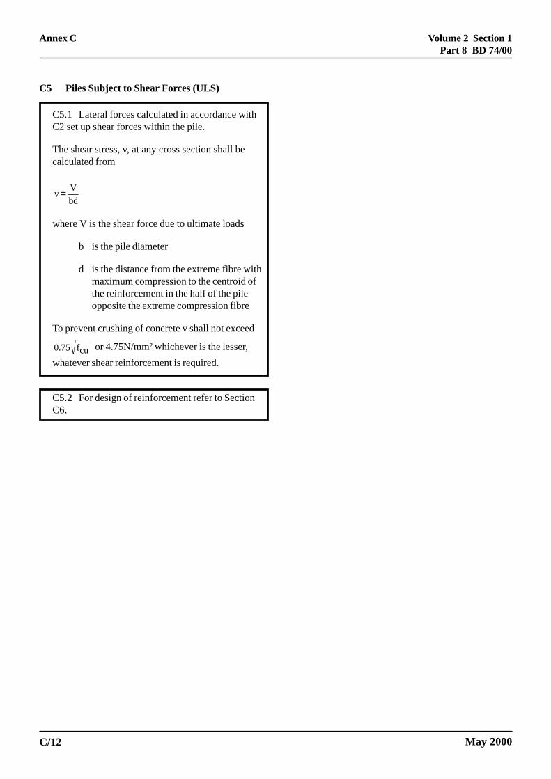
Volume 2 Section 1Part 8 BD 74/00
May 2000
C5 Piles Subject to Shear Forces (ULS)
C5.1 Lateral forces calculated in accordance withC2 set up shear forces within the pile.
The shear stress, v, at any cross section shall becalculated from
bd
V v =
where V is the shear force due to ultimate loads
b is the pile diameter
d is the distance from the extreme fibre withmaximum compression to the centroid ofthe reinforcement in the half of the pileopposite the extreme compression fibre
To prevent crushing of concrete v shall not exceed
cuf75.0 or 4.75N/mm² whichever is the lesser,
whatever shear reinforcement is required.
C5.2 For design of reinforcement refer to SectionC6.
C/12
Annex C

Volume 2 Section 1Part 8 BD 74/00
Annex C
C6 Shear Reinforcement
C6.1 Shear link reinforcement shall be providedwhere required in accordance with the followingcriteria:
*v
v2csξ
≤ No shear reinforcement required
(refer to Section C9)
* v v v
c2cs
sξξ
≤≤ Minimum reinforcement (refer
to Section C9).
* v > v csξ The greater of( )
ms
s
γ
ξyv
cvsv f
v -v b s = A or minimum
reinforcement requirements inaccordance with Section C9.
where Asv
is the cross sectional area of alllegs of the links at a particularcross section
v is the applied shear stress
vc
is the ultimate shear stress inconcrete calculated in accordancewith Table 8 of BS 5400: Part 4:1990 where the area of longitudinalreinforcement A
s to be used to
calculate vc shall be taken as the
area of reinforcement which is inthe half of the column opposite theextreme compression fibre. Theeffective depth shall be taken as thedistance from the extreme fibrewith maximum compression to thecentroid of this reinforcement. Theweb width shall be taken as thecolumn diameter.
ξs
is the depth factor (refer to Table 9of BS 5400: Part 4: 1990)
sv
is the spacing of the links along themember
b is the pile diameter
fyv
is the characteristic strength of linkreinforcement but not greater than460N/mm²
CS
May 2000
γms
is the partial safety factor for steelreinforcement
* ξsv
cshall be multiplied byin these instances.
where N is the ultimate axial load (innewtons). Refer also to C4.8.1.5
Ac
is the area of the entire concretesection (in mm²).
C6.2 The spacing of the legs of links in thedirection of the span and at right-angles to it shallnot exceed 0.75d.
C6.3 At any cross section additional longitudinalreinforcement is required in the tensile zone (inexcess of that required to resist bending) such that
( )ysa 0.87f2
V A ≥
where
Asa
is the area of effectively anchoredadditional longitudinal tensilereinforcement
fy
is the characteristic strength of thelongitudinal reinforcement
V is the shear force due to ultimate loads
Note: For symmetrical arrangements ofreinforcement this will result in a totalrequired area of reinforcement equal to 2 xA
sa spaced evenly round the perimeter of the
pile.
6.4 Enhanced Shear Strength of Sections Close toupports
Refer to BS 5400: Part 4: 1990 Clause 5.3.3.3 asimplemented by BD 24 (DMRB 1.3.1)
C6.5 The minimum reinforcement requirements inSection C9 shall be provided.
cA
0.05N 1+
C/13

Volume 2 Section 1Part 8 BD 74/00
Annex C
C7 Early Thermal Cracking
C7.1 General
C7.1.1 Fully embedded piles restrained alongtheir outer surfaces by the surrounding ground cansuffer from the effects of both externally andinternally restrained early thermal cracking. Due tothe insulating properties of the surrounding groundexternally restrained cracking is usually thedominant factor. This type of cracking canpenetrate through the entire concrete section and isgenerally horizontal except at positions close to thepile head where restraint from the pile cap maycause vertical cracking. Checks shall be carried outto ensure that the longitudinal steel does not yieldand that the cracked pile section shall be capable ofresisting applied shear forces.
C7.1.2 Sections 7.2 and 7.3 need only beimplemented if reinforcement is required to complywith other sections of this Annex.
C7.2 Control of Thermal Cracking
To ensure the reinforcement in the pile will not yieldbefore the tensile strength of the immature concreteis exceeded the following equation shall besatisfied:
cy
cts A
f
*f A =
where
As
is the total cross sectional area ofeffectively anchored longitudinalreinforcement distributed evenlyaround the perimeter of the pile.
Ac
is the effective concrete area of the pilewhich is equal to the gross crosssectional area for sections up to500mm thick (diameter). For sectionswith a diameter greater than 500mmdia it shall be taken as that area ofconcrete which lies within 250mm ofthe surface.
fy
is the characteristic tensile strength ofthe reinforcement
CS
C/14
fct* is the tensile strength of immature
concrete which may be taken as0.37 √(f
cu)
fcu
is the characteristic cube strength ofconcrete
7.3 Shear Resistance of Sections at Ultimate Limittate Subject to Early Thermal Cracking
C7.3.1 Piles shall be designed to withstandapplied shear forces in conjunction with the effectsof early thermal cracking. The shear resistance ofpiles subject to early thermal cracking should becalculated using the following method:
Longitudinal reinforcement shall be provided inaccordance with the following equation:
yys f
T15.1
0.73f
V A +≥
where
V is the shear force due to ultimate loads
T is the tensile axial force due toultimate loads
As
is the total cross sectional area ofeffectively anchored longitudinalreinforcement crossing a crackedsection
fy
is the characteristic strength ofeffectively anchored reinforcementcrossing a cracked section
Notes
i) The first term of this equation isderived from equation reference 61 inBS 8110: Part 1, “Structural Use ofConcrete” with tan α taken as 1.4. Theconstant 0.73 is the product of 0.6(constant stated in equation reference61), 1.4 (value of tan α) and 0.87(1/γ
m)
May 2000

Volume 2 Section 1Part 8 BD 74/00
Annex C
C7.4 Requirements for Longitudinal Reinforcement
C7.4.1 The area of longitudinal reinforcementcalculated in accordance with Sections C7.2 andC7.3 shall be compared to the summed longitudinalreinforcement requirements, calculated inaccordance with Sections C4 and C6. The greatestarea calculated in accordance with Section C7.2,C7.3 and the summed requirements of Section C4and C6 shall be specified.
May 2000 C/15
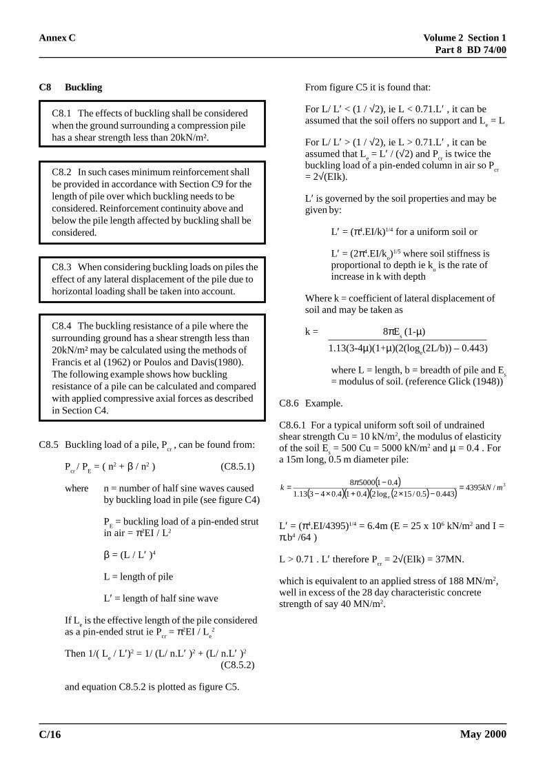
Volume 2 Section 1Part 8 BD 74/00
Annex C
C8 Buckling
C8.1 The effects of buckling shall be consideredwhen the ground surrounding a compression pilehas a shear strength less than 20kN/m².
C8.2 In such cases minimum reinforcement shallbe provided in accordance with Section C9 for thelength of pile over which buckling needs to beconsidered. Reinforcement continuity above andbelow the pile length affected by buckling shall beconsidered.
C8.3 When considering buckling loads on piles theeffect of any lateral displacement of the pile due tohorizontal loading shall be taken into account.
C8.4 The buckling resistance of a pile where thesurrounding ground has a shear strength less than20kN/m² may be calculated using the methods ofFrancis et al (1962) or Poulos and Davis(1980).The following example shows how bucklingresistance of a pile can be calculated and comparedwith applied compressive axial forces as describedin Section C4.
C8.5 Buckling load of a pile, Pcr , can be found from:
Pcr
/ PE = ( n2 + β / n2 ) (C8.5.1)
where n = number of half sine waves causedby buckling load in pile (see figure C4)
PE = buckling load of a pin-ended strut
in air = π2EI / L2
β = (L / L′ )4
L = length of pile
L′ = length of half sine wave
If Le is the effective length of the pile considered
as a pin-ended strut ie Pcr = π2EI / L
e2
Then 1/( Le / L′)2 = 1/ (L/ n.L′ )2 + (L/ n.L′ )2
(C8.5.2)
and equation C8.5.2 is plotted as figure C5.
C/16
From figure C5 it is found that:
For L/ L′ < (1 / √2), ie L < 0.71.L′ , it can beassumed that the soil offers no support and L
e = L
For L/ L′ > (1 / √2), ie L > 0.71.L′ , it can beassumed that L
e = L′ / (√2) and P
cr is twice the
buckling load of a pin-ended column in air so Pcr
= 2√(EIk).
L′ is governed by the soil properties and may begiven by:
L′ = (π4.EI/k)1/4 for a uniform soil or
L′ = (2π4.EI/ko)1/5 where soil stiffness is
proportional to depth ie ko is the rate of
increase in k with depth
Where k = coefficient of lateral displacement ofsoil and may be taken as
k = 8πEs (1-µ)
1.13(3-4µ)(1+µ)(2(loge(2L/b)) – 0.443)
where L = length, b = breadth of pile and Es
= modulus of soil. (reference Glick (1948))
C8.6 Example.
C8.6.1 For a typical uniform soft soil of undrainedshear strength Cu = 10 kN/m2, the modulus of elasticityof the soil E
s = 500 Cu = 5000 kN/m2 and µ = 0.4 . For
a 15m long, 0.5 m diameter pile:
( )( )( ) ( )( )
3/4395443.05.0/152log24.014.04313.1
4.0150008mkNk
e
=−×+×−
−= π
L′ = (π4.EI/4395)1/4 = 6.4m (E = 25 x 106 kN/m2 and I =π.b4 /64 )
L > 0.71 . L′ therefore Pcr = 2√(EIk) = 37MN.
which is equivalent to an applied stress of 188 MN/m2,well in excess of the 28 day characteristic concretestrength of say 40 MN/m2.
May 2000

Volume 2 Section 1Part 8 BD 74/00
May 2000
� � � � �
� � � � �
� � � � �
� � � � � � � � � �
� � � � � � � � � �
� � � � � � � � �
� � � �� �
� �
Figure C4: Buckled Form of Piles of Various Depths in a Uniform Medium (after Francis et al 1962)
C/17
Annex C
√√√√√2.L'
L'
L'

Volum
e 2 Section 1P
art 8 BD
74/00
May 2000
� � � � � � � � � �
� � � � �
� � � �
/ � 0 � � � � � � � � � ! � � � �
1'�- � � � � �
- 2 �
� 2 -
3 &�� � ���� �� !� ��� ��� 4
� �
��� � � � �
� � ��
� �� �� �
Figure C5: Graph of Le / L′′′′′ and L/ L′′′′′ for Pin-Ended Pile in Uniform Soil (after Francis et al 1962)
C/18
Annex C
L e=
L
Le/L'
L/L'

Volume 2 Section 1Part 8 BD 74/00
Annex C
C9 Minimum Reinforcement Requirements
C9.1 Where the application of this Annex,including Section C12, does not lead to arequirement for pile reinforcement, there is no needto comply with the minimum reinforcementsrequirement in this Section. Where reinforcement isrequired to comply with Sections C4, C6, C7 andC8 it shall not be less than the minimum areasstated below, or less than the reinforcement areasthat might be required to comply with Section C12.
C9.2 Longitudinal Reinforcement
C9.2.1 Where reinforcement is required to resistbending or axial tension forces, the area ofreinforcement spaced evenly around the perimeterof the pile shall be not less than 0.3% of the crosssectioned area of the pile, πb2 /4
where b is the pile diameter
C9.2.2 Where reinforcement is required to resistaxial compression forces or where the effects ofbuckling need to be considered the greater of thefollowing areas of reinforcement shall be provided:
i) Minimum of 0.3% of the cross sectional areaof the pile
ii) Minimum of 6 No bars spaced evenly aroundthe perimeter subject to a maximum spacingof 300mm.
Minimum bar size, shall be 12mm diameter.
iii) Not less than 0.15N/fy , where N is the
ultimate axial load acting on the pile and fy is
the characteristic strength of the longitudinalreinforcement.
C9.3 Transverse Reinforcement (Links)
The provision of nominal transverse reinforcementis required to resist buckling, to comply with shearrequirements as stated in Section C6.1 or to ensure
C9.3axialbuckminishall
Linklargecons
Spacthe ssecti
C9.3sheathe f
sv A
wher
Asv
b
Sv
fyv
C9.3onlythe rprovis ofrema
May 2000
a rigid reinforcement cage for handling andinstallation purposes.
.1 Where reinforcement is required to resist compression forces or where the effects ofling need to be considered the followingmum area of transverse (link) reinforcement be provided.
s shall be at least one-quarter the size of thest longitudinal bar at the section underideration.
ing of links shall be no greater than 12 timesize of the smallest longitudinal bar at theon under consideration.
.2 Where reinforcement is required to resistr forces the area of reinforcement shall satisfyollowing equation:
yv
v
0.87f
0.4bS ≥
e:
is the cross sectioned area of all the legs ofthe links at a particular cross section.
is the pile diameter
is the link spacing
is the characteristic strength of linkreinforcement
.3 For handling and installation purposes, in order to contain longitudinal reinforcement,equirements of Clause 9.3.1 may be relaxedided that the transverse reinforcement specified a suitable size and spacing to ensure the cageins rigid during handling and installation.
C/19
Volume 2 Section 1Part 8 BD 74/00
May 2000
C10 Curtailment of Reinforcement
C10.1Longitudinal Reinforcement
Longitudinal reinforcement may be curtailed to suitthe applied bending moments, axial and shearforces acting on the pile.
Gradual curtailment of reinforcement is to beconsidered to discourage horizontal cracking at thepoint of sudden curtailment of all longitudinal steel.For gradual curtailment the following aspectsshould be considered:
• Depending on the way in whichreinforcement is curtailed, the orientation ofthe cage may be significant;
• In the case of piles where reinforcement ispushed into the pile after placing theconcrete, the rigidity of the curtailed steelcage shall be designed to ensure that handlingand installation is not affected. (See SectionC12)
Sudden curtailment of reinforcement can beaccepted provided that the pile is checked at thepoint of curtailment to ensure it is adequate in itscracked state.
C10.2Transverse Reinforcement
Transverse reinforcement (links) may be curtailedto suit the applied shear forces acting on the pile, inaccordance with the requirements of Section C6 andC12.
C/20
Annex C

Volume 2 Section 1Part 8 BD 74/00
Annex C
C11 Corrosion and Durability/Control of CrackWidths (SLS)
C11.1 For the general case of a fully embedded pilein non aggressive ground as defined in BD42(DMRB 2.1.2), ready access to oxygen is restrictedto a distance of one metre below the surface of thenaturally occurring ground surrounding the pile.Corrosion action on reinforcement within the pilebelow this point is likely to be initially slow and,once started, quickly stopped by the deposition ofsolids. However, if the natural ground at depthbelow 1 metre is loose granular material withbrakish or saline groundwater, the requirements forthe first metre shall be applied over this type ofground.
C11.2 Protection of reinforcement in piles fromcorrosion under all conditions is best achieved bygood initial site investigation and the provision ofdense durable concrete in accordance with SectionsC2 and C3.
C11.3 Control of crack widths has little effect onthe corrosion of reinforcement. The control of crackwidths in accordance with the requirements ofClause 5.8.8.2 of BS 5400: Part 4: 1990 asimplemented by BD 24 (DMRB 1.3.1) shall berestricted to any section of a pile that is within 1metre of the naturally occurring ground surface.The cover for the purposes of this calculation shallbe as stated in Section C3 ignoring the additionalrequirements of BS 8004.
C11.4 Heavy corrosion can occur when one or moreof the following is present:
• rapid flow of oxygen or carbon dioxide richgroundwater
• highly acidic groundwater
• heavy carbonation of the concrete
May 2000
Where aggressive environments are identified crackwidths shall be controlled in accordance with therequirements of Clause 5.8.8.2 of BS5400:Part4:1990 as implemented by BD24 (DRMB 1.3.1)over the length of pile surrounded by groundclassified as aggressive or very aggressive inaccordance with BD42 (DMRB 2.1.2). In additionto the specification of concrete resistant tocarbonation attack, a protective cover to thereinforcement or protection with a sleeve of a noncorrosive or sacrificial material may be considered.
C11.5 The effects of sulphate resisting cement andThaumasite action should be considered byreference to the following documents:
BRE Digest 363: 1991: Sulfate and acid resistancein the ground.
DETR (1999) The thaumasite form of sulphateattack: Risks, diagnosis, remedial works andguidance on new construction. Report of theThaumasite Expert Group. January 1999. TheStationery Office.
C/21

Volume 2 Section 1Part 8 BD 74/00
May 2000
C12 Construction Considerations Affecting Design
C12.1 Whatever design requirement there may befor reinforcement it shall be increased if necessaryto ensure a rigid cage for handling and installationpurposes to suit the proposed method ofconstruction.
C12.2 Consideration shall be given to events thatmay arise on site during installation of the piles,and all subsequent construction operations thatcould result in the piles being subjected to loadeffects that are more onerous than design loadeffects already considered in the foregoing sections.This is of particular importance where noreinforcement is required to meet the otherrequirements of this Annex. The following list,which is not intended to be exhaustive, detailsconsiderations that could result in a decision tospecify or to increase the quantity of reinforcementrequired to ensure the piles remain serviceable.
• Piles subject to accidental impact fromconstruction equipment.
• Piles subject to construction operations, forexample breaking down of pile heads.
• Piles subject to load testing, static ordynamic.
• Piles subject to lateral loading from:
i) differences in ground levels due toexcavation/surcharging of adjacentareas before propping is effective.
ii) passage of construction traffic withininfluencing distance of the piles.
iii) variance between the constructionsequence implemented and thatassumed.
C/22
Annex C

Volume 2 Section 1Part 8 BD 74/00
May 2000
C13. References
Glick G W (1948) “Influence of soft ground on thedesign of long piles.” Proc 2nd Int Conf Soil Mechanics,Rotterdam, Vol 4 pp84 – 88.
TRL Report 144 (1995) “Design of reinforcement inpiles” J P Tyson, Transport Research Laboratory,Crowthorne, Berkshire.
C/23
Annex C


![ON THE FOUNDATIONS OF MATHEMATICAL …cob.jmu.edu/rosserjb/on the foundations of mathematical... · Web viewKumaraswamy Vela Velupillai [74] presents a constructivist perspective](https://static.fdocuments.in/doc/165x107/5b0b9d627f8b9a99488e2eec/on-the-foundations-of-mathematical-cobjmuedurosserjbon-the-foundations-of-mathematicalweb.jpg)