
BBR_ETA-12_0076_CMF_EN_Rev2_0912
56
BBR VT CONA CMF BT Internal Post-tensioning System with Flat Anchorages European Technical Approval ETA – 12/0076
-
Upload
trannguyenviet -
Category
Documents
-
view
16 -
download
0
Transcript of BBR_ETA-12_0076_CMF_EN_Rev2_0912

BB
R V
T C
ON
A C
MF
BT
Inte
rnal
Pos
t-te
nsio
ning
Sys
tem
with
Fla
t Anc
hora
ges
European Technical ApprovalETA – 12/0076

The delivery note accompanying components of the BBR VT CONA CMI BT Post-tensioning System will contain the CE marking.
Assembly and installation of BBR VT CONA CMI BT tendons must only be carried out by qualified BBR PT Specialist Companies. Find the local BBR PT Specialist Company by visiting the BBR Network website www.bbrnetwork.com.
European Organisation for Technical ApprovalsEuropäische Organisation für Technische ZulassungenOrganisation Européenne pour l’Agrément technique
Guideline for European Technical Approval of Post-tensioning Kits for Prestressing of Structures
Requirements for the installation of post-tensioning kits for prestressing of structures and qualification of the specialist company and its personnel
BBR E-Trace is the trading and quality assurance platform of the BBR Network linking the Holder of Approval, BBR VT International Ltd, BBR PT Specialist Companies and the BBR Manufacturing Plant. Along with the established BBR Factory Production Control, BBR E-Trace provides effective supply chain management including installation, delivery notes and highest quality standards, as well as full traceability of components.
Year
PT Specialist Company
Company
ww
w.bbrnetwork.com
ETAG 013
CWA 14646
0432
ETA-12/0076BBR VT CONA CMF
Internal Post-tensioning System with Flat Anchorages and 02, 03 and 04 Strands
BBR VT International LtdBahnstrasse 23, 8603 Schwerzenbach (Switzerland)
www.bbrnetwork.com
0432-CPD-11 9181-1.7/1
12

elec
tron
ic c
opy
ele
ctro
nic
copy
ele
ctro
nic
copy
ele
ctro
nic
copy
ele
ctro
nic
copy
ele
ctro
nic
copy
European technical approval ETA-12/0076English translation, the original version is in German
Handelsbezeichnung BBR VT CONA CMF BT – Internes Spannverfahren mit flachen Verankerungen und 02, 03 und 04 Litzen
Trade name BBR VT CONA CMF BT – Internal Post-tensioning System with Flat Anchorages and 02, 03, and 04 Strands
Zulassungsinhaber
Holder of approval
BBR VT International Ltd. Bahnstrasse 23 8603 Schwerzenbach (ZH) Switzerland
Zulassungsgegenstand und Verwendungszweck
Litzen-Spannverfahren, intern, im Verbund oder ohne Verbund, für das Vorspannen von Tragwerken
Generic type and use of construction product
Post-tensioning kit for prestressing of structures with internal bonded or unbonded strands
Geltungsdauer vom
Validity from
29.06.2012
bis zum
to
28.06.2017
Herstellwerk
Manufacturing plant
BBR VT International Ltd. Bahnstrasse 23 8603 Schwerzenbach (ZH) Switzerland
Diese Europäische technische Zulassung umfasst
49 Seiten einschließlich 26 Anhängen
This European technical approval contains
49 Pages including 26 Annexes

Page 2 of European technical approval ETA-12/0076 Validity from 29.06.2012 to 28.06.2017
OIB-250-001/07-022
elec
tron
ic c
opy
ele
ctro
nic
copy
ele
ctro
nic
copy
ele
ctro
nic
copy
ele
ctro
nic
copy
ele
ctro
nic
copy
Table of contents EUROPEAN TECHNICAL APPROVAL ETA-12/0076 ...................................................................................... 1 TABLE OF CONTENTS .................................................................................................................................... 2 I LEGAL BASES AND GENERAL CONDITIONS ........................................................................................... 5 II SPECIFIC CONDITIONS OF THE EUROPEAN TECHNICAL APPROVAL......................................................... 6 1 DEFINITION OF PRODUCT AND INTENDED USE ....................................................................................... 6 1.1 Definition of product .......................................................................................................................... 6 1.2 Intended use...................................................................................................................................... 7 2 CHARACTERISTICS OF THE PRODUCT AND METHODS OF VERIFICATION .................................................. 7 PT SYSTEM .................................................................................................................................................. 7 2.1 Designation and range of the anchorages and couplers................................................................... 7
2.1.1 Designation .............................................................................................................................. 7 2.1.2 Anchorage................................................................................................................................ 7 2.1.2.1 General .................................................................................................................................... 7 2.1.2.2 Restressable and exchangeable tendon.................................................................................. 8 2.1.3 Fixed coupler............................................................................................................................ 8 2.1.3.1 General .................................................................................................................................... 8 2.1.3.2 Sleeve coupler (FH, SH) .......................................................................................................... 8 2.1.4 Movable coupler (BH) .............................................................................................................. 8 2.1.5 Layout of the anchorage recesses........................................................................................... 8
2.2 Designation and range of the tendons .............................................................................................. 9 2.2.1 Designation .............................................................................................................................. 9 2.2.2 Range ...................................................................................................................................... 9 2.2.2.1 CONA CMF BT n05-93............................................................................................................ 9 2.2.2.2 CONA CMF BT n05-100.......................................................................................................... 9 2.2.2.3 CONA CMF BT n06-140 .......................................................................................................... 9 2.2.2.4 CONA CMF BT n06-150 ........................................................................................................ 10
2.3 Ducts ............................................................................................................................................... 10 2.3.1 Use of ducts ........................................................................................................................... 10 2.3.1.1 Bonded tendon....................................................................................................................... 10 2.3.1.2 Unbonded tendon .................................................................................................................. 10 2.3.2 Degree of filling ...................................................................................................................... 10 2.3.3 Round steel strip sheaths....................................................................................................... 10 2.3.4 Flat steel ducts....................................................................................................................... 10 2.3.5 Plastic sheaths....................................................................................................................... 11 2.3.6 Pre-bent smooth round steel ducts ........................................................................................ 11
2.4 Minimum radii of curvature .............................................................................................................. 11 2.4.1 Minimum radii of curvature for bonded and unbonded tendons other than monostrand
tendons .................................................................................................................................. 11 2.4.2 Minimum radii of curvature for tendons with monostrands..................................................... 12
2.5 Support of tendons .......................................................................................................................... 12 2.5.1 Support of bonded and unbonded tendons other than monostrand tendons......................... 12 2.5.2 Support of monostrand tendons............................................................................................. 12
2.6 Friction losses ................................................................................................................................. 13 2.7 Slip at anchorages and couplers ..................................................................................................... 13 2.8 Concrete strength at time of stressing............................................................................................. 14 2.9 Centre spacing and edge distance of anchorages .......................................................................... 14 COMPONENTS ............................................................................................................................................ 15

Page 3 of European technical approval ETA-12/0076 Validity from 29.06.2012 to 28.06.2017
OIB-250-001/07-022
elec
tron
ic c
opy
ele
ctro
nic
copy
ele
ctro
nic
copy
ele
ctro
nic
copy
ele
ctro
nic
copy
ele
ctro
nic
copy
2.10 Strands ............................................................................................................................................ 15 2.11 Anchorages and couplers................................................................................................................ 15
2.11.1 General .................................................................................................................................. 15 2.11.2 Anchor heads......................................................................................................................... 15 2.11.3 Bearing trumplates................................................................................................................. 16 2.11.4 Trumpets ................................................................................................................................ 16 2.11.5 Coupler anchor heads H ........................................................................................................ 16 2.11.6 Ring wedges .......................................................................................................................... 16 2.11.7 Helix and additional reinforcement......................................................................................... 16 2.11.8 Protection caps ...................................................................................................................... 16 2.11.9 Material properties ................................................................................................................. 16
2.12 Permanent corrosion protection ...................................................................................................... 17 2.13 Dangerous substances.................................................................................................................... 17 2.14 Methods of verification .................................................................................................................... 17 2.15 Identification .................................................................................................................................... 17 3 EVALUATION OF CONFORMITY AND CE MARKING ................................................................................ 18 3.1 Attestation of conformity system ..................................................................................................... 18 3.2 Responsibilities ............................................................................................................................... 18
3.2.1 Tasks for the manufacturer – factory production control........................................................ 18 3.2.2 Tasks of the approved body................................................................................................... 19 3.2.2.1 Initial type testing of the products........................................................................................... 19 3.2.2.2 Initial inspection of factory and of factory production control ................................................. 19 3.2.2.3 Continuous surveillance......................................................................................................... 19 3.2.2.4 Audit testing of samples taken at the factory ......................................................................... 19
3.3 CE marking...................................................................................................................................... 19 4 ASSUMPTIONS UNDER WHICH THE FITNESS OF THE PRODUCT FOR THE INTENDED USE WAS
FAVOURABLY ASSESSED.................................................................................................................... 20 4.1 Manufacturing.................................................................................................................................. 20 4.2 Design ............................................................................................................................................. 20
4.2.1 General .................................................................................................................................. 20 4.2.2 Anchorage recess .................................................................................................................. 20 4.2.3 Reinforcement in the anchorage zone ................................................................................... 20 4.2.4 Fatigue resistance.................................................................................................................. 21 4.2.5 Tendons in masonry structures – Load transfer to the structure............................................ 21 4.2.6 Maximum prestressing force .................................................................................................. 21
4.3 Installation ....................................................................................................................................... 21 4.4 Stressing operation ......................................................................................................................... 21 4.5 Restressing ..................................................................................................................................... 22 4.6 Exchanging tendons........................................................................................................................ 22 4.7 Filling material ................................................................................................................................. 22
4.7.1 Grout ...................................................................................................................................... 22 4.7.2 Grease and wax..................................................................................................................... 22 4.7.3 Recordings............................................................................................................................. 22
4.8 Welding ........................................................................................................................................... 23 5 RECOMMENDATIONS FOR THE MANUFACTURER .................................................................................. 23 5.1 Recommendations for packing, transport and storage.................................................................... 23 5.2 Recommendations on installation ................................................................................................... 23 5.3 Accompanying information .............................................................................................................. 23

Page 4 of European technical approval ETA-12/0076 Validity from 29.06.2012 to 28.06.2017
OIB-250-001/07-022
elec
tron
ic c
opy
ele
ctro
nic
copy
ele
ctro
nic
copy
ele
ctro
nic
copy
ele
ctro
nic
copy
ele
ctro
nic
copy
ANNEXES................................................................................................................................................... 24 ANNEX 1 OVERVIEW ON ANCHORAGES AND COUPLERS FOR BONDED AND UNBONDED TENDONS OTHER
THAN MONOSTRAND TENDONS.................................................................................................. 24 ANNEX 2 OVERVIEW ON ANCHORAGES AND COUPLERS FOR MONOSTRANDS AND VT CMM BANDS ........... 25 ANNEX 3 ANCHOR HEADS ....................................................................................................................... 26 ANNEX 4 BEARING TRUMPLATE AND H-COUPLER..................................................................................... 27 ANNEX 5 TRUMPETS............................................................................................................................... 28 ANNEX 6 WEDGES, SPRING AND PROTECTION CAP .................................................................................. 29 ANNEX 7 ANCHORAGES WITH MONOSTRANDS OR VT CMM BANDS.......................................................... 30 ANNEX 8 TENDON RANGES ..................................................................................................................... 31 ANNEX 9 MINIMUM RADIUS OF CURVATURE OF DUCT ............................................................................... 32 ANNEX 10 MINIMUM WALL THICKNESS OF DUCT ......................................................................................... 33 ANNEX 11 MATERIAL CHARACTERISTICS ................................................................................................... 34 ANNEX 12 CONTENTS OF THE PRESCRIBED TEST PLAN .............................................................................. 35 ANNEX 13 AUDIT TESTING ........................................................................................................................ 36 ANNEX 14 MAXIMUM PRESTRESSING AND OVERSTRESSING FORCES .......................................................... 37 ANNEX 15 CONSTRUCTION STAGES .......................................................................................................... 38 ANNEX 16 MINIMUM CONCRETE STRENGTH – HELIX – ADDITIONAL REINFORCEMENT – CENTRE
SPACING AND EDGE DISTANCE .................................................................................................. 39 ANNEX 17 MINIMUM CONCRETE STRENGTH – HELIX – ADDITIONAL REINFORCEMENT – CENTRE
SPACING AND EDGE DISTANCE .................................................................................................. 40 ANNEX 18 MODIFICATION OF CENTRE SPACING AND EDGE DISTANCE ......................................................... 41 ANNEX 19 FREE TENDON LAYOUT WITH MONOSTRANDS OR VT CMM BANDS – TENDON CONA CMF
BT 0405 AND 0406.................................................................................................................. 42 ANNEX 20 DESCRIPTION OF INSTALLATION OF BONDED AND UNBONDED TENDONS OTHER THAN
MONOSTRAND TENDONS........................................................................................................... 43 ANNEX 21 DESCRIPTION OF INSTALLATION OF MONOSTRANDS OR VT CMM BANDS.................................... 44 ANNEX 22 SPECIFICATION ........................................................................................................................ 45 ANNEX 23 SPECIFICATION ........................................................................................................................ 46 ANNEX 24 STRAND SPECIFICATION ........................................................................................................... 47 ANNEX 25 REFERENCE DOCUMENTS......................................................................................................... 48 ANNEX 26 REFERENCE DOCUMENTS......................................................................................................... 49

Page 5 of European technical approval ETA-12/0076 Validity from 29.06.2012 to 28.06.2017
OIB-250-001/07-022
elec
tron
ic c
opy
ele
ctro
nic
copy
ele
ctro
nic
copy
ele
ctro
nic
copy
ele
ctro
nic
copy
ele
ctro
nic
copy
I LEGAL BASES AND GENERAL CONDITIONS
1 This European technical approval is issued by Österreichisches Institut für Bautechnik in accordance with:
1. Council Directive 89/106/EEC of 21 December 1988 on the approximation of laws, regulations and administrative provisions of Member States relating to construction products 1 – Construction Products Directive (CPD) –, amended by the Council Directive 93/68/EEC of 22 July 1993 2, and Regulation (EC) 1882/2003 of the European Parliament and of the Council of 29 September 2003 3;
2. dem Salzburger Bauproduktegesetz, LGBl. Nr. 11/1995, in der Fassung LGBl. Nr. 47/1995, LGBl. Nr. 63/1995, LGBl. Nr. 123/1995, LGBl. Nr. 46/2001, LGBl. Nr. 73/2001, LGBl. Nr. 99/2001 und LGBl. Nr. 20/2010;
the Salzburg Construction Products Act LGBl. № 11/1995, amended by LGBl. № 47/1995, LGBl. № 63/1995, LGBl. № 123/1995, LGBl. № 46/2001, LGBl. № 73/2001, LGBl. № 99/2001, and LGBl. № 20/2010;
3. Common Procedural Rules for Requesting, Preparing and the Granting of European technical approvals set out in the Annex of Commission Decision 94/23/EC 4;
4. Guideline for European technical approval of Post-Tensioning Kits for Prestressing of Structures, ETAG 013, Edition June 2002.
2 Österreichisches Institut für Bautechnik is authorised to check whether the provisions of this European technical approval are met. Checking may take place in the manufacturing plant. Nevertheless, the responsibility for the conformity of the products to the European technical approval and for their fitness for the intended use remains with the holder of the European technical approval.
3 This European technical approval is not to be transferred to manufacturers or agents of manufacturers other than those indicated on Page 1, or manufacturing plants other than those indicated on Page 1 of this European technical approval.
4 This European technical approval may be withdrawn by Österreichisches Institut für Bautechnik, in particular pursuant to information by the Commission according to Article 5 (1) of Council Directive 89/106/EEC.
5 Reproduction of this European technical approval including transmission by electronic means shall be in full. However, partial reproduction may be made with the written consent of Österreichisches Institut für Bautechnik. In this case partial reproduction has to be designated as such. Texts and drawings of advertising brochures shall not contradict or misuse the European technical approval.
6 The European technical approval is issued by the Approval Body in its official language. This version corresponds to the version circulated within EOTA. Translations into other languages have to be designated as such.
1 Official Journal of the European Communities № L 40, 11.02.1989, page 12 2 Official Journal of the European Communities № L 220, 30.08.1993, page 1 3 Official Journal of the European Union № L 284, 31.10.2003, page 1 4 Official Journal of the European Communities № L 17, 20.01.1994, page 34

Page 6 of European technical approval ETA-12/0076 Validity from 29.06.2012 to 28.06.2017
OIB-250-001/07-022
elec
tron
ic c
opy
ele
ctro
nic
copy
ele
ctro
nic
copy
ele
ctro
nic
copy
ele
ctro
nic
copy
ele
ctro
nic
copy
II SPECIFIC CONDITIONS OF THE EUROPEAN TECHNICAL APPROVAL
1 Definition of product and intended use 1.1 Definition of product
The European technical approval (ETA) applies to a kit, the PT system
BBR VT CONA CMF BT – Internal Post-tensioning System with Flat Anchorage and
02, 03, and 04 strands, comprising the following components:
− Tendon
Internal tendons with 02 to 04 tensile elements
− Tensile element
7-wire prestressing steel strand with nominal diameters and maximum characteristic tensile strength as given in Table 1
Unbonded 7-wire prestressing steel monostrand with nominal diameters and maximum characteristic tensile strength as given in Table 1, factory-provided with a corrosion protection system consisting of a corrosion protection filling material and an HDPE-sheathing
Table 1: Tensile elements
Designation Nominal diameter
Nominal cross sectional area
Maximum characteristic tensile strength
⎯ mm mm2 MPa
12.5 93 05
12.9 100
15.3 140 06
15.7 150
1 860
NOTE 1 MPa = 1 N/mm2
− Anchorage and coupler
Anchorage of the strands with ring wedges
End anchorage
Fixed (passive) anchor or stressing (active) anchor as end anchorage for 02, 03, and 04 strands
Fixed or stressing coupler
Sleeve coupler for 02, 03, and 04 strands
Movable coupler
Sleeve coupler for 02, 03, and 04 strands
− Bearing trumplate for 02, 03, and 04 strands
− Helix and additional reinforcement in the region of the anchorage
− Corrosion protection for tensile elements, anchorages and couplers

Page 7 of European technical approval ETA-12/0076 Validity from 29.06.2012 to 28.06.2017
OIB-250-001/07-022
elec
tron
ic c
opy
ele
ctro
nic
copy
ele
ctro
nic
copy
ele
ctro
nic
copy
ele
ctro
nic
copy
ele
ctro
nic
copy
1.2 Intended use The PT system is intended to be used for the prestressing of structures.
Use categories according to type of tendon and material of structure:
− Internal bonded tendon for concrete and composite structures
− Internal unbonded tendon for concrete and composite structures
− For special structures according to Eurocode 2 and Eurocode 4, and Eurocode 6
Optional use categories:
− Restressable tendons
− Exchangeable tendons
The provisions made in the European technical approval are based on an assumed intended working life of the PT system of 100 years. The indications given on the working life of the PT system cannot be interpreted as a guarantee given by the manufacturer or the Approval Body, but are to be regarded only as a means for selecting the appropriate product in relation to the expected, economically reasonable working life of the construction works.
2 Characteristics of the product and methods of verification
PT system 2.1 Designation and range of the anchorages and couplers
End anchorages can be used as fixed or stressing anchors. Couplers are fixed or movable. The principal dimensions of anchorages and couplers are given in the Annexes 3 to 7, and 16 and 17.
2.1.1 Designation
End anchorage e.g. S A CONA CMF BT 0206-150 1860
Stressing (S) or fixed (F)
Anchorage
Designation of the tendon with information on number, cross sectional area and characteristic tensile strength of the strands
Coupler, e.g. F H CONA CMF BT 0206-150 1860
Fixed (F), stressing (S) or movable (B)
Coupler anchor head (H) for sleeve coupler
Designation of the tendon with information on number, cross sectional area and characteristic tensile strength of the strands
2.1.2 Anchorage
2.1.2.1 General
The anchor heads of the stressing and fixed anchorages are identical. A differentiation is needed for the construction works. The wedges of inaccessible fixed anchors shall be secured

Page 8 of European technical approval ETA-12/0076 Validity from 29.06.2012 to 28.06.2017
OIB-250-001/07-022
elec
tron
ic c
opy
ele
ctro
nic
copy
ele
ctro
nic
copy
ele
ctro
nic
copy
ele
ctro
nic
copy
ele
ctro
nic
copy
with springs and/or a wedge retaining plate. An alternative is pre-locking each single strand with ~ 0.5 · Fpk and applying a wedge retaining plate.
Where
Fpk ........ Nominal value of maximum force of single strand
2.1.2.2 Restressable and exchangeable tendon
Significant to a restressable and exchangeable tendon is the excess length of the strands. The extent of the excess length depends on the jack used for restressing or releasing. The protrusions of the strands require a permanent corrosion protection and an adapted cap.
2.1.3 Fixed coupler
2.1.3.1 General
The prestressing force at the second construction stage shall not be greater than that at the first construction stage, neither during construction, nor in the final state, nor due to any load combination.
2.1.3.2 Sleeve coupler (FH, SH)
The coupler anchor heads H are of the same basic geometry as the anchor heads of the fixed and stressing anchors. Compared to the anchor heads of the fixed and stressing anchors, the coupler anchor heads H are higher and provide an external thread for the coupler sleeve.
The connection between the coupler anchor heads H of the first and second construction stages is achieved by means of a coupler sleeve.
2.1.4 Movable coupler (BH)
The movable coupler is a sleeve coupler in a coupler sheathing box made of steel or plastic. Length and position of the coupler sheathing box shall be for the expected strain displacement, see Clause 4.3.
The coupler anchor heads and the coupler sleeves of the movable couplers are identical to the coupler heads and the coupler sleeves of the fixed couplers.
A 100 mm long and at least 3.5 mm thick HDPE insert shall be installed at the deviating point of the strands at the end of the trumpet. This insert is not required for a plastic trumpet where the duct is slipped over the plastic trumpet.
2.1.5 Layout of the anchorage recesses
All anchor heads have to be placed perpendicular to the axis of the tendon, see Annex 15.
The dimensions of the anchorage recesses shall be adapted to the prestressing jacks used. The ETA holder shall save for reference information on the minimum dimensions of the anchorage recesses. The formwork for the anchorage recesses should be slightly conical for ease of removal.
In case of internal anchorages fully embedded in concrete, the recesses shall be designed so as to permit a reinforced concrete cover with the required dimensions and in any case with a thickness of at least 20 mm. In case of exposed anchorages, concrete cover of the anchorage and bearing trumplate is not required. However, the exposed surface of the bearing trumplate and the cap shall be provided with corrosion protection.
Page 9 of European technical approval ETA-12/0076 Validity from 29.06.2012 to 28.06.2017
OIB-250-001/07-022
elec
tron
ic c
opy
ele
ctro
nic
copy
ele
ctro
nic
copy
ele
ctro
nic
copy
ele
ctro
nic
copy
ele
ctro
nic
copy
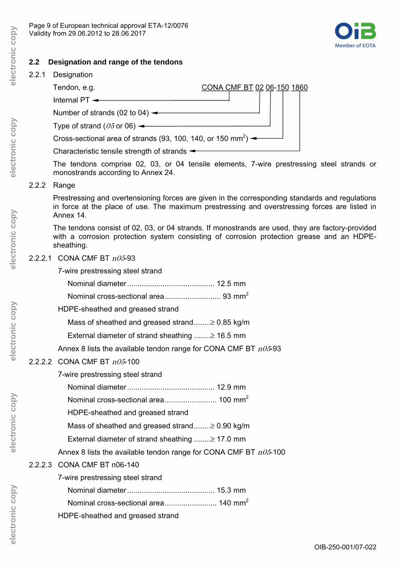
2.2 Designation and range of the tendons 2.2.1 Designation
Tendon, e.g. CONA CMF BT 02 06-150 1860
Internal PT
Number of strands (02 to 04)
Type of strand (05 or 06)
Cross-sectional area of strands (93, 100, 140, or 150 mm2)
Characteristic tensile strength of strands
The tendons comprise 02, 03, or 04 tensile elements, 7-wire prestressing steel strands or monostrands according to Annex 24.
2.2.2 Range
Prestressing and overtensioning forces are given in the corresponding standards and regulations in force at the place of use. The maximum prestressing and overstressing forces are listed in Annex 14.
The tendons consist of 02, 03, or 04 strands. If monostrands are used, they are factory-provided with a corrosion protection system consisting of corrosion protection grease and an HDPE-sheathing.
2.2.2.1 CONA CMF BT n05-93
7-wire prestressing steel strand
Nominal diameter .......................................... 12.5 mm
Nominal cross-sectional area........................... 93 mm2
HDPE-sheathed and greased strand
Mass of sheathed and greased strand........≥ 0.85 kg/m
External diameter of strand sheathing ........≥ 16.5 mm
Annex 8 lists the available tendon range for CONA CMF BT n05-93
2.2.2.2 CONA CMF BT n05-100
7-wire prestressing steel strand
Nominal diameter .......................................... 12.9 mm
Nominal cross-sectional area......................... 100 mm2
HDPE-sheathed and greased strand
Mass of sheathed and greased strand........≥ 0.90 kg/m
External diameter of strand sheathing ........≥ 17.0 mm
Annex 8 lists the available tendon range for CONA CMF BT n05-100
2.2.2.3 CONA CMF BT n06-140
7-wire prestressing steel strand
Nominal diameter .......................................... 15.3 mm
Nominal cross-sectional area......................... 140 mm2
HDPE-sheathed and greased strand

Page 10 of European technical approval ETA-12/0076 Validity from 29.06.2012 to 28.06.2017
OIB-250-001/07-022
elec
tron
ic c
opy
ele
ctro
nic
copy
ele
ctro
nic
copy
ele
ctro
nic
copy
ele
ctro
nic
copy
ele
ctro
nic
copy
Mass of sheathed and greased strand........≥ 1.23 kg/m
External diameter of strand sheathing ........≥ 19.5 mm
Annex 8 lists the available tendon range for CONA CMF BT n06-140
2.2.2.4 CONA CMF BT n06-150
7-wire prestressing steel strand
Nominal diameter .......................................... 15.7 mm
Nominal cross-sectional area......................... 150 mm2
HDPE-sheathed and greased strand
Mass of sheathed and greased strand........≥ 1.31 kg/m
External diameter of strand sheathing ........≥ 20.0 mm
Annex 8 lists the available tendon range for CONA CMF BT n06-150
2.3 Ducts 2.3.1 Use of ducts
2.3.1.1 Bonded tendon
For bonded tendons in general corrugated ducts either in steel or in plastic shall be used. Smooth steel ducts may be used if permitted at the place of use.
2.3.1.2 Unbonded tendon
For unbonded tendons smooth ducts or monostrands can be used.
2.3.2 Degree of filling
The degree of filling, f, for bonded and unbonded tendons other than monostrand tendons in round ducts shall generally be between 0.25 and 0.35. The minimum radii of curvature can be defined with the equation given in Clause 2.4. Typical degrees of filling, f, and corresponding minimum radii of curvature, Rmin, are given in Annex 9. The degree of filling is defined as
f = cross sectional area of prestressing steel
cross sectional area of inner diameter of sheath
2.3.3 Round steel strip sheaths
Steel strip sheaths in conformity with EN 523 5 shall be used. The degree of filling, f, shall be according to Clause 2.3.2 and the minimum radii of curvature to Clause 2.4.
Annex 9 gives internal duct diameters and minimum radii of curvature in which the pressure under the strand, pR, has been set to 140 kN/m and 200 kN/m respectively. Different duct diameter and smaller radii of curvature are acceptable according to the respective standards and regulations in force at the place of use.
2.3.4 Flat steel ducts
For tendons with 02, 03, or 04 strands flat ducts, either smooth or corrugated, may be used, whereas EN 523 applies accordingly. The flat ducts shall be free of any kinks.
Annex 9 gives minor and major internal flat duct dimensions and minimum radii of curvature, both minor and major, in which the pressure under the strand, pR, has been set to 140 kN/m and 200 kN/m respectively. Different duct dimensions and smaller radius of curvature are acceptable according to the respective standards and regulations in force at the place of use.
5 Reference documents are listed in the Annexes 25 and 26

Page 11 of European technical approval ETA-12/0076 Validity from 29.06.2012 to 28.06.2017
OIB-250-001/07-022
elec
tron
ic c
opy
ele
ctro
nic
copy
ele
ctro
nic
copy
ele
ctro
nic
copy
ele
ctro
nic
copy
ele
ctro
nic
copy
2.3.5 Plastic sheaths
Corrugated plastic sheaths made of HDPE or PP conforming to ETAG 013, Annex C.3, shall be used. Alternatively smooth plastic ducts according to EN 12201 may be used if permitted at the place of use. The degree of filling, f, shall conform to Clause 2.3.2 and the minimum radii of curvature to Clause 2.4.
Annex 10 gives duct diameters and minimum wall thicknesses for corrugated and smooth plastic ducts according to Clause 2.3. Different internal diameters, wall thicknesses or materials are acceptable according to the respective standards and regulations in force at the place of use.
2.3.6 Pre-bent smooth round steel ducts
If permitted at the place of use, smooth steel ducts according to EN 10255, EN 10216-1, EN 10217-1, EN 10219-1 or EN 10305-5 can be used. The degree of filling, f, shall conform to Clause 2.3.2 and the minimum radii of curvature to Clause 2.4. The ducts shall be pre-bent and free of any kinks. The minimum wall thickness of the steel ducts shall meet the requirements of Annex 10.
Different internal diameters or wall thicknesses are acceptable according to the respective standards and regulations in force at the place of use.
2.4 Minimum radii of curvature 2.4.1 Minimum radii of curvature for bonded and unbonded tendons other than monostrand tendons
− The minimum radii of curvature for prestressing steel strands, Rmin, given in Annex 9 correspond to a prestressing force of the tendon of 0.85 · Fp0.1
− a nominal diameter of the strand of d = 12.9 mm and d = 15.7 mm
− a maximum pressure under the prestressing steel strands of pR, max = 140 kN/m and 200 kN/m
− a concrete compressive strength of fcm, 0, cube ≥ 21 MPa.
In case of different tendon parameters or a different pressure under the prestressing steel strands, the calculation of the minimum radii of curvature of the tendon for round ducts can be carried out using the equation
Rmin = max
⎩⎪⎨⎪⎧≥
Fpm, 0
pR ⋅ kn
and
≥ 400 ⋅ d3 000
Table 2: Factor kn
Factor
kn
Number of strands
n f ~ 0.25 f ~ 0.30 f ~ 0.35
02 0.68 0.87 ⎯
03 0.61 0.71 0.88
04 0.65
Page 12 of European technical approval ETA-12/0076 Validity from 29.06.2012 to 28.06.2017
OIB-250-001/07-022
elec
tron
ic c
opy
ele
ctro
nic
copy
ele
ctro
nic
copy
ele
ctro
nic
copy
ele
ctro
nic
copy
ele
ctro
nic
copy
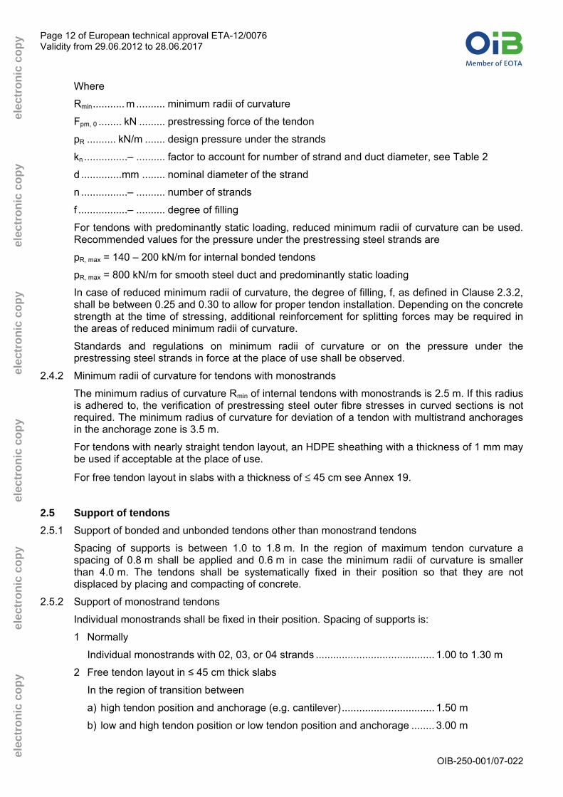
Where
Rmin........... m .......... minimum radii of curvature
Fpm, 0 ........ kN ......... prestressing force of the tendon
pR .......... kN/m ....... design pressure under the strands
kn ...............– .......... factor to account for number of strand and duct diameter, see Table 2
d ..............mm ........ nominal diameter of the strand
n ................– .......... number of strands
f .................– .......... degree of filling
For tendons with predominantly static loading, reduced minimum radii of curvature can be used. Recommended values for the pressure under the prestressing steel strands are
pR, max = 140 – 200 kN/m for internal bonded tendons
pR, max = 800 kN/m for smooth steel duct and predominantly static loading
In case of reduced minimum radii of curvature, the degree of filling, f, as defined in Clause 2.3.2, shall be between 0.25 and 0.30 to allow for proper tendon installation. Depending on the concrete strength at the time of stressing, additional reinforcement for splitting forces may be required in the areas of reduced minimum radii of curvature.
Standards and regulations on minimum radii of curvature or on the pressure under the prestressing steel strands in force at the place of use shall be observed.
2.4.2 Minimum radii of curvature for tendons with monostrands
The minimum radius of curvature Rmin of internal tendons with monostrands is 2.5 m. If this radius is adhered to, the verification of prestressing steel outer fibre stresses in curved sections is not required. The minimum radius of curvature for deviation of a tendon with multistrand anchorages in the anchorage zone is 3.5 m.
For tendons with nearly straight tendon layout, an HDPE sheathing with a thickness of 1 mm may be used if acceptable at the place of use.
For free tendon layout in slabs with a thickness of ≤ 45 cm see Annex 19.
2.5 Support of tendons 2.5.1 Support of bonded and unbonded tendons other than monostrand tendons
Spacing of supports is between 1.0 to 1.8 m. In the region of maximum tendon curvature a spacing of 0.8 m shall be applied and 0.6 m in case the minimum radii of curvature is smaller than 4.0 m. The tendons shall be systematically fixed in their position so that they are not displaced by placing and compacting of concrete.
2.5.2 Support of monostrand tendons
Individual monostrands shall be fixed in their position. Spacing of supports is:
1 Normally
Individual monostrands with 02, 03, or 04 strands ......................................... 1.00 to 1.30 m
2 Free tendon layout in ≤ 45 cm thick slabs
In the region of transition between
a) high tendon position and anchorage (e.g. cantilever)................................ 1.50 m
b) low and high tendon position or low tendon position and anchorage ........ 3.00 m

Page 13 of European technical approval ETA-12/0076 Validity from 29.06.2012 to 28.06.2017
OIB-250-001/07-022
elec
tron
ic c
opy
ele
ctro
nic
copy
ele
ctro
nic
copy
ele
ctro
nic
copy
ele
ctro
nic
copy
ele
ctro
nic
copy
In regions of the high or low tendon position the tendons shall be connected in an appropriate way to the reinforcement mesh, at least at two points with spacing of 0.3 to 1.3 m. The reinforcement mesh shall be fixed in its position. Special spacers for tendons are therefore not required. For details see Annex 19.
2.6 Friction losses For the calculation of loss of prestressing force due to friction Coulomb’s law applies. Friction losses in anchorages are low and do not have to be taken into consideration in design and execution. The calculation of the friction losses is carried out using the equation
Fx = F0 · e - μ · (α + k · x)
Where
Fx.......... kN .......... prestressing force at a distance x along the tendon
F0.......... kN .......... prestressing force at x = 0 m
μ ........... rad-1........ friction coefficient, see Table 3
k ........... rad/m...... wobble coefficient, see Table 3
α........... rad.......... sum of the angular displacements over distance x, irrespective of direction or sign
x ........... m............ distance along the tendon from the point where prestressing force is equal to F0
NOTE 1 rad = 1 m/m = 1
Table 3: Friction parameters
Recommended values Range of values
μ k μ k Type of duct
rad-1 rad/m rad-1 rad/m
Steel strip sheath 0.18 0.17 - 0.19
Smooth steel duct 0.18 0.16 - 0.24
Corrugated plastic sheath 0.12 0.10 - 0.14
Smooth plastic duct 0.12
0.005
0.10 - 0.14
0.004 - 0.007
Monostrand 0.06 0.009 0.05 - 0.07 0.008 – 0.011
NOTE As far as acceptable at the place of use, due to special measures like oiling or for a tendon layout with only few deviations the friction coefficient μ can be reduced by 10 to 20 %. Compared to e.g. the use of prestressing steel or sheaths with a film of rust this value increases by more than 100 %.
2.7 Slip at anchorages and couplers Slip at stressing and fixed anchorages and at fixed couplers, first and second construction stages, is 6 mm. Slip at movable couplers is twice this amount. At the stressing anchorage and at
Page 14 of European technical approval ETA-12/0076 Validity from 29.06.2012 to 28.06.2017
OIB-250-001/07-022
elec
tron
ic c
opy
ele
ctro
nic
copy
ele
ctro
nic
copy
ele
ctro
nic
copy
ele
ctro
nic
copy
ele
ctro
nic
copy
the first construction stage of fixed couplers the slip is 4 mm, provided a prestressing jack with a wedging system and a wedging force of around 25 kN per strand are used.
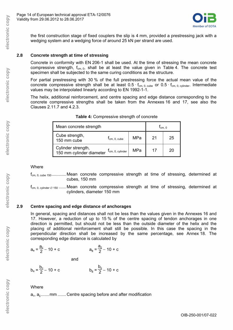
2.8 Concrete strength at time of stressing Concrete in conformity with EN 206-1 shall be used. At the time of stressing the mean concrete compressive strength, fcm, 0, shall be at least the value given in Table 4. The concrete test specimen shall be subjected to the same curing conditions as the structure.
For partial prestressing with 30 % of the full prestressing force the actual mean value of the concrete compressive strength shall be at least 0.5 · fcm, 0, cube or 0.5 · fcm, 0, cylinder. Intermediate values may be interpolated linearly according to EN 1992-1-1.
The helix, additional reinforcement, and centre spacing and edge distance corresponding to the concrete compressive strengths shall be taken from the Annexes 16 and 17, see also the Clauses 2.11.7 and 4.2.3.
Table 4: Compressive strength of concrete
Mean concrete strength fcm, 0
Cube strength, 150 mm cube fcm, 0, cube MPa 21 25
Cylinder strength, 150 mm cylinder diameter
fcm, 0, cylinder MPa 17 20
Where
fcm, 0, cube 150............ Mean concrete compressive strength at time of stressing, determined at cubes, 150 mm
fcm, 0, cylinder ∅ 150 ...... Mean concrete compressive strength at time of stressing, determined at cylinders, diameter 150 mm
2.9 Centre spacing and edge distance of anchorages In general, spacing and distances shall not be less than the values given in the Annexes 16 and 17. However, a reduction of up to 15 % of the centre spacing of tendon anchorages in one direction is permitted, but should not be less than the outside diameter of the helix and the placing of additional reinforcement shall still be possible. In this case the spacing in the perpendicular direction shall be increased by the same percentage, see Annex 18. The corresponding edge distance is calculated by
ae = ac
2 − 10 + c ae = ac
2 − 10 + c
and
be = bc
2 − 10 + c be = bc
2 − 10 + c
Where
ac, ac.......mm ....... Centre spacing before and after modification

Page 15 of European technical approval ETA-12/0076 Validity from 29.06.2012 to 28.06.2017
OIB-250-001/07-022
elec
tron
ic c
opy
ele
ctro
nic
copy
ele
ctro
nic
copy
ele
ctro
nic
copy
ele
ctro
nic
copy
ele
ctro
nic
copy
bc, bc.......mm ....... Centre spacing in the direction perpendicular to ac, before and after modification
ae, ae ......mm ....... Edge distance in the direction along to ac, before and after modification
be, be ......mm ....... Edge distance in the direction perpendicular to ae, before and after modification
c .............mm ....... Concrete cover
Standards and regulations on concrete cover in force at the place of use shall be observed.
The minimum values for ac, bc, ae, and be are given in the Annexes 16 and 17. NOTE The replacement of the additional stirrup reinforcement by a helix according to the
Annexes 16 and 17 does not prevent the modification of centre spacing and edge distance. The external dimensions of the rectangular helix replacing stirrups have to be adapted to the modified centre spacing and edge distance.
Components 2.10 Strands
Only 7-wire prestressing steel strands or monostrands with characteristics according to Table 5 shall be used, see also Annex 24. The corrosion protection system of the monostrand is as specified in ETAG 013, Annex C.1, see also the Annexes 22 and 23.
Table 5: Prestressing steel strands
Max. characteristic tensile strength 1) fpk MPa 1 860
Nominal diameter d mm 12.5 12.9 15.3 15.7
Nominal cross sectional area Ap mm2 93 100 140 150
Mass of prestressing steel M kg/m 0.73 0.78 1.09 1.17
Mass of monostrand M kg/m 0.85 0.90 1.23 1.31 1) Prestressing steel strands with a characteristic tensile strength below 1 860 MPa may
also be used.
In a single tendon only strands spun in the same direction shall be used.
2.11 Anchorages and couplers 2.11.1 General
The components of anchorages and couplers shall conform to the specifications given in the Annexes 3 to 7 and the technical documentation 6. Therein the component dimensions, materials and material identification data with tolerances are given.
2.11.2 Anchor heads
The anchor heads are made of steel and contain regularly arranged conical holes drilled in parallel to accommodate prestressing steel strands and wedges. The back exits of the bore holes are provided with bell mouth openings or plastic ring cushions. In addition, threaded bores may
6 The technical documentation of the European technical approval is deposited at Österreichisches Institut für Bautechnik and,
insofar as is relevant to the tasks of the approved body involved in the attestation of the conformity procedure, is handed over to the approved body.

Page 16 of European technical approval ETA-12/0076 Validity from 29.06.2012 to 28.06.2017
OIB-250-001/07-022
elec
tron
ic c
opy
ele
ctro
nic
copy
ele
ctro
nic
copy
ele
ctro
nic
copy
ele
ctro
nic
copy
ele
ctro
nic
copy
be provided to fix protection caps and wedge retaining plates. At the back of the anchor head there may be a step, for ease of centring the anchor head on the bearing trumplate.
2.11.3 Bearing trumplates
The bearing trumplates made of cast iron transmit the force via three anchorage planes to the concrete. Two identical bearing trumplates, with and without a front air-vent situated at the interface plane to the anchor head, are available. A grout inlet or ventilation tube can be fitted to this air-vent. On the tendon-side end there is an inner thread to accommodate the trumpet.
2.11.4 Trumpets
The conical trumpets made of steel or HDPE may have either a corrugated or a plain surface. At the duct-side end there is a radius for the deviation of the strands and a smooth surface, to ensure a good transition to the duct. The opposite end is connected to the bearing trumplate.
HDPE trumpets are equipped with a blind air-vent which might be opened and to which a grouting or ventilation tube can be connected. In the case of trumpets made completely out of steel sheet, a 100 mm long and at least 3.5 mm thick HDPE insert shall be installed at the deviating point of the strands on the steel duct side.
2.11.5 Coupler anchor heads H
The coupler anchor heads H for the sleeve coupler are made of steel and have the same basic geometry as the anchor heads of the fixed or stressing anchorages. Compared to the anchor heads of the fixed and stressing anchors, the coupler anchor heads H are higher and provide an external thread for the coupler sleeve. At the back of the coupler anchor heads H there is a step for ease of centring the coupler anchor head on the bearing trumplate.
The coupler sleeve is a steel tube with an inner thread and is provided with ventilation holes.
Ring cushions shall be inserted in the coupler head H2.
2.11.6 Ring wedges
The ring wedges are in three pieces, which are held together by spring rings. Three types of ring wedges are used. Within one anchorage or coupler only one type of ring wedge shall be used.
The wedges of inaccessible fixed anchors and couplers shall be secured with springs and/or a wedge retaining plate. An alternative is pre-locking each single strand with ~ 0.5 · Fpk and applying a wedge retaining plate as per Clause 2.1.2.1.
2.11.7 Helix and additional reinforcement
The helix and the additional reinforcement are made of ribbed reinforcing steel. The end of the helix at the anchorage side is welded to the following turn. The helix shall be placed exactly in the tendon axis. The dimensions of the helix and the additional reinforcement shall conform to the values specified in the Annexes 16 and 17.
If required for a specific project design, the reinforcement given in the Annexes 16 and 17 may be modified in accordance with the respective regulations in force at the place of use as well as with the relevant approval of the local authorities and of the ETA holder to provided equivalent performance.
2.11.8 Protection caps
Protection caps are made of steel or plastic. They are provided with air-vents and fixed with screws or threaded rods.
2.11.9 Material properties
Annex 11 lists the material properties and the standard/specification of the components

Page 17 of European technical approval ETA-12/0076 Validity from 29.06.2012 to 28.06.2017
OIB-250-001/07-022
elec
tron
ic c
opy
ele
ctro
nic
copy
ele
ctro
nic
copy
ele
ctro
nic
copy
ele
ctro
nic
copy
ele
ctro
nic
copy
2.12 Permanent corrosion protection To protect the tendons from corrosion, the ducts, couplers and anchorages have to be completely filled with grout according to EN 447, special grout according to ETAG 013, grease according ETAG 013, Annex C.4.1, or wax according ETAG 013, Annex C.4.2, as applicable at the place of use.
The corrosion protection materials used for monostrands are specified in ETAG 013, Annex C.1, see also the Annexes 22 and 23.
As an alternative grease or wax may be used, if according to the standards and regulations in force at the place of use.
With exposed anchorages, not fully embedded in concrete, an adequate corrosion protection for the exposed parts shall be applied.
2.13 Dangerous substances The release of dangerous substances is determined according to ETAG 013, Clause 5.3.1. The PT system conforms to the provisions of Guidance Paper H7 relating to dangerous substances.
A declaration in this respect has been made by the manufacturer.
In addition to the specific clauses relating to dangerous substances in the European technical approval, there may be other requirements applicable to the product falling within their scope (e.g. transposed European legislation and national laws, regulations and administrative provisions). In order to meet the provisions of the Construction Products Directive, these requirements also need to be complied with, when and where they apply.
2.14 Methods of verification The assessment of the fitness of the "BBR VT CONA CMF BT – Flat Anchorage System for Internal Post-tensioning with 02, 03, and 04 strands" for their intended use in relation to the requirements for mechanical resistance and stability in the sense of Essential Requirement 1 of the Council Directive 89/106/EEC has been made in conformity to the Guideline for European technical approvals of "Post-Tensioning Kits for Prestressing of Structures", ETAG 013, Edition June 2002.
2.15 Identification The European technical approval for the "BBR VT CONA CMF BT – Flat Anchorage System for Internal Post-tensioning with 02, 03, and 04 strands" is issued on the basis of agreed data, deposited with Österreichisches Institut für Bautechnik, which identifies the BBR VT CONA CMF BT System that has been assessed and judged. Changes to the production process of the BBR VT CONA CMF BT Post-tensioning System, which could result in this deposited data being incorrect, should be notified to Österreichisches Institut für Bautechnik before the changes are introduced. Österreichisches Institut für Bautechnik will decide whether or not such changes affect the European technical approval and consequently the validity of the CE marking on the basis of the European technical approval and, if so, whether further assessment or alterations to the European technical approval are considered necessary.
7 Guidance Paper H: A harmonised approach relating to dangerous substances under the Construction Products Directive,
Rev. September 2002.

Page 18 of European technical approval ETA-12/0076 Validity from 29.06.2012 to 28.06.2017
OIB-250-001/07-022
elec
tron
ic c
opy
ele
ctro
nic
copy
ele
ctro
nic
copy
ele
ctro
nic
copy
ele
ctro
nic
copy
ele
ctro
nic
copy
3 Evaluation of conformity and CE marking 3.1 Attestation of conformity system
The system of attestation of conformity assigned by the European Commission to this product in accordance with the Council Directive 89/106/EWG of 21 December 1988, Annex III 2. (i), referred to as System 1+, provides for:
Certification of the conformity of the product by an approved certification body on the basis of
(a) Tasks for the manufacturer
(1) Factory production control;
(2) Further testing of samples taken at the factory by the manufacturer in accordance with a prescribed test plan 8;
(b) Tasks for the approved body
(3) Initial type testing of the product;
(4) Initial inspection of factory and of factory production control;
(5) Continuous surveillance, assessment and approval of the factory production control;
(6) Audit testing of samples taken at the factory.
3.2 Responsibilities 3.2.1 Tasks for the manufacturer – factory production control
At the manufacturing plant, the manufacturer shall implement and continuously maintain a factory production control system. All the elements, requirements and provisions adopted by the manufacturer shall be documented systematically in the form of written operating and processing instructions. The factory production control system shall ensure that the product is in conformity with the European technical approval.
Within the framework of factory production control, the manufacturer shall carry out tests and controls in accordance with the prescribed test plan and in accordance with the European technical approval. Details of the extent, nature and frequency of testing and controls to be performed within the framework of the factory production control shall correspond to this prescribed test plan, which forms part of the technical documentation of the European technical approval.
The results of factory production control shall be recorded and evaluated. The records shall include at a minimum the following information.
− Designation of the products and the basic materials;
− Type of check or testing;
− Date of manufacture of the products and date of testing of the products or basic materials or components;
− Results of check and testing and, if appropriate, comparison with requirements;
− Name and signature of the person responsible for the factory production control.
The records of the factory production control shall be submitted to the approved body and shall be filed for at least 10 years time. On request, the records shall be presented to Österreichisches Institut für Bautechnik.
8 The prescribed test plan has to be deposited with Österreichisches Institut für Bautechnik and is handed over only to the
approved body involved in the conformity attestation procedure. The prescribed test plan is also referred to as control plan.

Page 19 of European technical approval ETA-12/0076 Validity from 29.06.2012 to 28.06.2017
OIB-250-001/07-022
elec
tron
ic c
opy
ele
ctro
nic
copy
ele
ctro
nic
copy
ele
ctro
nic
copy
ele
ctro
nic
copy
ele
ctro
nic
copy
If the test results are unsatisfactory, the manufacturer shall immediately implement measures to eliminate the defects. Construction products or components which are not in conformity with the requirements shall be removed. After elimination of the defects, the respective test – if verification is required for technical reasons – shall be repeated immediately.
The basic elements of the prescribed test plan conform to ETAG 013, Annex E.1, and are specified in the quality management plan of the "BBR VT CONA CMF BT – Flat Anchorage System for Internal Post-tensioning with 02, 03, and 04 strands".
Annex 12 lists the contents of the prescribed test plan.
3.2.2 Tasks of the approved body
3.2.2.1 Initial type testing of the products
For initial type testing the results of the tests performed as part of the assessment for the European technical approval may be used unless there are changes in the production procedure or factory plant. In such cases, the necessary initial type testing shall be agreed between Österreichisches Institut für Bautechnik and the approved body involved.
3.2.2.2 Initial inspection of factory and of factory production control
The approved body shall ascertain that, in accordance with the prescribed test plan, the manufacturing plant, in particular personnel and equipment, and the factory production control are suitable to ensure a continuous and orderly manufacturing of the PT system according to the specifications given in Section II as well as in the Annexes of the European technical approval.
3.2.2.3 Continuous surveillance
The kit manufacturer shall be inspected at least once a year. Each component manufacturer of the components listed in Annex 13 shall be inspected at least once every five years. It shall be verified that the system of factory production control and the specified manufacturing process are maintained, taking account of the prescribed test plan.
On demand the results of product certification and continuous surveillance shall be made available by the approved body to Österreichisches Institut für Bautechnik. If the provisions of the European technical approval and the prescribed test plan are no longer fulfilled, the certificate of conformity shall be withdrawn and Österreichisches Institut für Bautechnik informed immediately.
3.2.2.4 Audit testing of samples taken at the factory
During surveillance inspection, the approved body shall take samples at the factory of components of the PT system or of individual components, for which the European technical approval has been granted, for independent testing. For the most important components Annex 13 summarises the minimum procedures that shall be implemented by the approved body.
3.3 CE marking The delivery note of the components of the PT system shall contain the CE marking. The initials “CE” shall be followed by the identification number of the certification body and shall be accompanied by the following information.
− Name or identification mark and address of the manufacturer
− The last two digits of the year in which the CE marking was affixed
− Number of the European technical approval
− Number of the certificate of conformity

Page 20 of European technical approval ETA-12/0076 Validity from 29.06.2012 to 28.06.2017
OIB-250-001/07-022
elec
tron
ic c
opy
ele
ctro
nic
copy
ele
ctro
nic
copy
ele
ctro
nic
copy
ele
ctro
nic
copy
ele
ctro
nic
copy
− Product identification (trade name)
4 Assumptions under which the fitness of the product for the intended use was favourably assessed
4.1 Manufacturing "BBR VT CONA CMF BT – Flat Anchorage System for Internal Post-tensioning with 02, 03, and 04 strands" is manufactured in accordance with the provisions of the European technical approval. Composition and manufacturing process are deposited at Österreichisches Institut für Bautechnik.
4.2 Design 4.2.1 General
Design of the structure shall permit correct installation and stressing of the tendons. The reinforcement in the anchorage zone shall permit correct placing and compacting of concrete.
4.2.2 Anchorage recess
The dimensions of the anchorage recesses are to be adapted to the prestressing jacks used. The ETA holder shall save for reference information on the minimum dimensions of the anchorage recesses and appropriate clearance behind the anchorage.
In case of anchorages fully embedded in concrete, the recesses shall be designed so as to permit a reinforced concrete cover with the required dimensions and in any case with a thickness of at least 20 mm.
In case of exposed anchorages concrete cover of the anchorage and bearing trumplate is not required. However, the exposed surface of the bearing trumplate and the cap shall be provided with a corrosion protection.
4.2.3 Reinforcement in the anchorage zone
Verification of the transfer of prestressing forces to structural concrete is not required if the centre spacing and edge distances of the anchorages as well as grade and dimensions of additional reinforcement, see the Annexes 16 and 17, are conformed to. In the case of grouped anchorages the additional reinforcement of the individual anchorages can be combined, provided appropriate anchorage is ensured. However, the number, cross section and position with respect to the bearing trumplates shall remain unchanged.
Centre spacing and edge distances as well as concrete strength and reinforcement for larger tendons in terms of strength, nominal diameter and number of strands are as well applicable to smaller tendons.
NOTE For example it is fully applicable to fit a tendon CMF BT 0305-93 into an anchorage zone, detailed and executed for a CMF BT 0406-150 tendon.
The reinforcement of the structure shall not be employed as additional reinforcement. Reinforcement exceeding the required reinforcement of the structure may be used as additional reinforcement, if appropriate placing is possible.
The forces outside the area of the additional reinforcement shall be verified and, if necessary, dealt with by appropriate reinforcement.
If required for a specific project design, the reinforcement given in the Annexes 16 and 17 may be modified in accordance with the respective regulations in force at the place of use as well as with the relevant approval of the local authority and of the ETA holder to provide equivalent performance.

Page 21 of European technical approval ETA-12/0076 Validity from 29.06.2012 to 28.06.2017
OIB-250-001/07-022
elec
tron
ic c
opy
ele
ctro
nic
copy
ele
ctro
nic
copy
ele
ctro
nic
copy
ele
ctro
nic
copy
ele
ctro
nic
copy
4.2.4 Fatigue resistance
Fatigue resistance of the tendons has been tested with an upper force of 0.65 · Fpk and with a stress range of 80 N/mm2 up to 2 · 106 load cycles.
4.2.5 Tendons in masonry structures – Load transfer to the structure
Load transfer of prestressing force from the anchorages to masonry structures shall be via concrete or steel members, designed according to the European technical approval, especially according to the Clauses 2.8, 2.9, 2.11.7, and 4.2.3 or Eurocode 3, respectively.
The concrete or steel members supporting the anchorages shall have dimensions that permit a force of 1.1 · Fpk to be transferred to the masonry. The verification shall be performed according to Eurocode 6 as well as to the respective standards and regulations in force at the place of use.
4.2.6 Maximum prestressing force
Annex 14 lists the maximum prestressing and overstressing forces.
4.3 Installation Assembly and installation of tendons shall only be carried out by qualified PT specialist companies with the required resources and experience in the use of multi strand internal post-tensioning systems, see ETAG 013, Annex D.1, and CWA 14646. The respective standards and regulations in force at the place of use shall be considered. The company’s PT site manager shall have a certificate, stating that she or he has been trained by the ETA holder and that she or he possesses the necessary qualifications and experience with the "BBR VT CONA CMF BT – Flat Anchorage System for Internal Post-tensioning with 02, 03, and 04 strands".
The tendons may be manufactured on site or in the factory (prefabricated tendons).
To avoid confusion it is recommended to, in general, use on one site prestressing steel strands with one nominal diameter only.
Bearing trumplate, anchor head and coupler anchor head shall be placed perpendicular to the tendon’s axis.
Couplers shall be situated in a straight tendon section.
At the anchorages and couplers the tendon layout shall provide a straight section over a length of at least 250 mm beyond the end of the trumpet.
Before placing the concrete a final check of the installed tendons has to be carried out.
In case of a movable coupler it shall be ensured by means of appropriate position and length of coupler sheathing box and trumpet that a displacement of the movable coupler of at least 1.15 ⋅ Δl + 30 mm is possible without any hindrance, where Δl in mm is the maximum expected displacement of the coupler at stressing.
4.4 Stressing operation With a mean concrete compressive strength in the anchorage zone according to the values laid down in the Annexes 16 and 17 full prestressing may be applied.
Stressing and, if applicable, wedging shall be carried out using a suitable prestressing jack. The wedging force shall correspond to approximately ~ 25 kN per wedge.
After realising the prestressing force from the prestressing jack, the tendon length reduces by the amount of wedge draw-in, slip, at the anchor head.

Page 22 of European technical approval ETA-12/0076 Validity from 29.06.2012 to 28.06.2017
OIB-250-001/07-022
elec
tron
ic c
opy
ele
ctro
nic
copy
ele
ctro
nic
copy
ele
ctro
nic
copy
ele
ctro
nic
copy
ele
ctro
nic
copy
Elongation and prestressing forces shall be checked continuously during the stressing operation. The results of the prestressing operation shall be recorded and the measured elongations shall be compared with the prior calculated values.
The ETA holder shall save information on the prestressing jacks and the appropriate clearance behind the anchorage.
The safety-at-work and health protection regulations shall be complied with.
4.5 Restressing Restressing of tendons in combination with release and reuse of wedges is permitted, whereby the wedges shall bite into at least 15 mm of virgin strand surface and no wedge bites shall remain inside the final length of the tendon between anchorages.
For tendons remaining restressable throughout the working life of the structure, wax or grease shall be used as filling material for corrosion protection. Moreover, a strand protrusion at the stressing anchor has to remain with a length compatible with the prestressing jack used.
4.6 Exchanging tendons Exchange of tendons is permitted.
The specifications for the exchangeable tendons shall be defined during the design phase. The radii of curvature should be reasonable larger than the minimum radii given in Clause 2.4 as to not impair the plastic duct or monostrand sheathing by wear due to stressing of the tendon.
Exchangeable tendons are unbonded.
For exchangeable tendons, wax or grease shall be used as filling material for corrosion protection. Moreover, a strand protrusion has to remain at the stressing anchor with a length allowing safe release of the complete prestressing force.
Stressing and fixed anchorages shall be accessible and adequate space has to be provided behind the anchorages.
4.7 Filling material 4.7.1 Grout
Grout shall be injected through the inlet holes until it escapes from the outlet tubes with the same consistency. To avoid voids in the hardened grout special measures shall be applied for long tendons, tendon paths with distinct high points or inclined tendons. All vents and grouting inlets shall be sealed immediately after grouting. The standards to be observed for cement grouting in prestressing ducts are EN 445, EN 446, and EN 447 or the standards and regulations in force at the place of use shall be applied for ready mixed grout.
4.7.2 Grease and wax
The specifications in ETAG 013, Annex C.4, and the recommendations of the supplier are relevant for grease and wax.
The filling procedure with grease and wax shall follow a similar procedure as the one specified for filling with grout.
4.7.3 Recordings
The results of the filling operation shall be recorded. The respective standards and regulations in force at the place of use shall be observed.

Page 23 of European technical approval ETA-12/0076 Validity from 29.06.2012 to 28.06.2017
OIB-250-001/07-022
elec
tron
ic c
opy
ele
ctro
nic
copy
ele
ctro
nic
copy
ele
ctro
nic
copy
ele
ctro
nic
copy
ele
ctro
nic
copy
4.8 Welding Ducts may be welded.
The helix may be welded to the bearing trumplate to secure its position.
After installation of the tendons further welding shall not be carried out on the tendons. In case of welding operations near tendons precautionary measures are required to avoid damage.
5 Recommendations for the manufacturer 5.1 Recommendations for packing, transport and storage
During transport of prefabricated tendons a minimum diameter of curvature of 1.65 m shall be observed.
The ETA holder shall have instructions related to
− Temporary protection of prestressing steels and components in order to prevent corrosion during transportation from the production site to the job site;
− Transportation, storage and handling of the tensile elements and of other components in order to avoid any mechanical, chemical or electrochemical changes;
− Protection of tensile elements and other components from moisture;
− Keeping tensile elements away from areas where welding operations are performed.
5.2 Recommendations on installation The manufacturer’s installation instructions shall be followed, see ETAG 013, Annex D.3. The respective standards and regulations in force at the place of use shall be observed. For the installation see also the Annexes 20 to 22.
5.3 Accompanying information It is the responsibility of the ETA holder to ensure that all necessary information on design and installation is submitted to those responsible for the design and execution of the structures executed with "BBR VT CONA CMF BT – Flat Anchorage System for Internal Post-tensioning with 02, 03, and 04 strands".
On behalf of Österreichisches Institut für Bautechnik
The original document is signed by:
Rainer Mikulits
Managing Director

Page 24 of European technical approval ETA-12/0076 Validity from 29.06.2012 to 28.06.2017
OIB-250-001/07-022
elec
tron
ic c
opy
ele
ctro
nic
copy
ele
ctro
nic
copy
ele
ctro
nic
copy
ele
ctro
nic
copy
ele
ctro
nic
copy
CONA CMF BT
Internal Post-tensioning System Overview on anchorages and couplers for
bonded and unbonded tendons other than monostrand tendons
Annex 1 of European technical approval
ETA-12/0076

Page 25 of European technical approval ETA-12/0076 Validity from 29.06.2012 to 28.06.2017
OIB-250-001/07-022
elec
tron
ic c
opy
ele
ctro
nic
copy
ele
ctro
nic
copy
ele
ctro
nic
copy
ele
ctro
nic
copy
ele
ctro
nic
copy
CONA CMF BT
Internal Post-tensioning System Overview on anchorages and couplers for
monostrands and VT CMM Bands
Annex 2 of European technical approval
ETA-12/0076
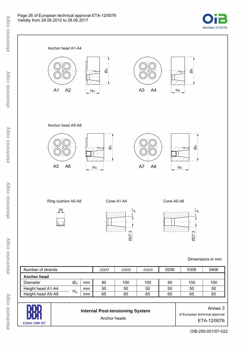
Page 26 of European technical approval ETA-12/0076 Validity from 29.06.2012 to 28.06.2017
OIB-250-001/07-022
elec
tron
ic c
opy
ele
ctro
nic
copy
ele
ctro
nic
copy
ele
ctro
nic
copy
ele
ctro
nic
copy
ele
ctro
nic
copy
Dimensions in mm
Number of strands 0205 0305 0405 0206 0306 0406
Anchor head Diameter ØA mm 90 100 100 90 100 100 Height head A1-A4 mm 50 50 50 50 50 50 Height head A5-A8
HA mm 65 65 65 65 65 65
CONA CMF BT
Internal Post-tensioning System Anchor heads
Annex 3 of European technical approval
ETA-12/0076

Page 27 of European technical approval ETA-12/0076 Validity from 29.06.2012 to 28.06.2017
OIB-250-001/07-022
elec
tron
ic c
opy
ele
ctro
nic
copy
ele
ctro
nic
copy
ele
ctro
nic
copy
ele
ctro
nic
copy
ele
ctro
nic
copy
Dimensions in mm
Number of strands 0205 0305 0405 0206 0306 0406
Coupler head H1 Nominal diameter ØAH mm 90 100 100 90 100 100 Height HAH mm 50 50 55 50 50 55
Coupler head H2 Diameter ØAH mm 90 100 100 90 100 100 Height HAH mm 65 65 65 65 65 65
Coupler sleeve H1 Diameter ØH mm 114 121 130 114 121 130 Length LH mm 180 180 180 180 180 180
CONA CMF BT
Internal Post-tensioning System Bearing trumplate and H-coupler
Annex 4 of European technical approval
ETA-12/0076

Page 28 of European technical approval ETA-12/0076 Validity from 29.06.2012 to 28.06.2017
OIB-250-001/07-022
elec
tron
ic c
opy
ele
ctro
nic
copy
ele
ctro
nic
copy
ele
ctro
nic
copy
ele
ctro
nic
copy
ele
ctro
nic
copy
Dimensions in mm
CONA CMF BT
Internal Post-tensioning System Trumpets
Annex 5 of European technical approval
ETA-12/0076

Page 29 of European technical approval ETA-12/0076 Validity from 29.06.2012 to 28.06.2017
OIB-250-001/07-022
elec
tron
ic c
opy
ele
ctro
nic
copy
ele
ctro
nic
copy
ele
ctro
nic
copy
ele
ctro
nic
copy
ele
ctro
nic
copy
Dimensions in mm
Number of strands 0205 0305 0405 0206 0306 0406
Wedge retaining plate KS Minimum diameter ØKS mm 65 73 75 65 73 75 Thickness DKS mm 5 5 5 5 5 5
CONA CMF BT
Internal Post-tensioning System Wedges, spring and protection cap
Annex 6 of European technical approval
ETA-12/0076

Page 30 of European technical approval ETA-12/0076 Validity from 29.06.2012 to 28.06.2017
OIB-250-001/07-022
elec
tron
ic c
opy
ele
ctro
nic
copy
ele
ctro
nic
copy
ele
ctro
nic
copy
ele
ctro
nic
copy
ele
ctro
nic
copy
Dimensions in mm
CONA CMF BT
Internal Post-tensioning System Anchorages with monostrands or
VT CMM Bands
Annex 7 of European technical approval
ETA-12/0076

Page 31 of European technical approval ETA-12/0076 Validity from 29.06.2012 to 28.06.2017
OIB-250-001/07-022
elec
tron
ic c
opy
ele
ctro
nic
copy
ele
ctro
nic
copy
ele
ctro
nic
copy
ele
ctro
nic
copy
ele
ctro
nic
copy
CONA CMF n05-93
Characteristic value of maximum
force of tendon Number of strands Nominal cross-
sectional area of prestressing steel
Nominal mass of prestressing steel
fpk = 1 860 MPa
n Ap M Fpk ⎯ mm2 kg/m kN 02 186 1.45 346 03 279 2.18 519 04 372 2.91 692
CONA CMF n05-100
Characteristic value of maximum
force of tendon Number of strands Nominal cross-
sectional area of prestressing steel
Nominal mass of prestressing steel
fpk = 1 860 MPa
n Ap M Fpk ⎯ mm2 kg/m kN 02 200 1.56 372 03 300 2.34 558 04 400 3.12 744
CONA CMF n06-140
Characteristic value of maximum
force of tendon Number of strands Nominal cross-
sectional area of prestressing steel
Nominal mass of prestressing steel
fpk = 1 860 MPa n Ap M Fpk ⎯ mm2 kg/m kN 02 280 2.19 520 03 420 3.28 780 04 560 4.37 1 040
CONA CMF n06-150
Characteristic value of maximum
force of tendon Number of strands Nominal cross-
sectional area of prestressing steel
Nominal mass of prestressing steel
fpk = 1 860 MPa n Ap M Fpk ⎯ mm2 kg/m kN 02 300 2.34 558 03 450 3.52 837 04 600 4.69 1 116
CONA CMF BT
Internal Post-tensioning System Tendon ranges
Annex 8 of European technical approval
ETA-12/0076

Page 32 of European technical approval ETA-12/0076 Validity from 29.06.2012 to 28.06.2017
OIB-250-001/07-022
elec
tron
ic c
opy
ele
ctro
nic
copy
ele
ctro
nic
copy
ele
ctro
nic
copy
ele
ctro
nic
copy
ele
ctro
nic
copy
Inner diameter of round duct, di, and minimum radii of curvature, Rmin, for pR, max = 140 kN/m
Number of strands f ≈ 0.25 f ≈ 0.30 f ≈ 0.35
n05 n06 di Rmin di Rmin di Rmin — mm m mm m mm m
0205 30 1.7 30 1.8 30 1.8 0305 40 1.8 35 2.1 35 2.6 0405 45 2.6 40 2.6 40 2.6 0206 40 2.0 35 2.6 35 2.6 0306 50 2.7 45 3.2 40 3.9 0406 55 3.9 50 3.9 45 3.9
Inner diameter of round duct, di, and minimum radii of curvature, Rmin, for pR, max = 200 kN/m Number of
strands f ≈ 0.25 f ≈ 0.30 f ≈ 0.35
n05 n06 di Rmin di Rmin di Rmin — mm m mm m mm m
0205 30 1.7 30 1.7 30 1.7 0305 40 1.7 35 1.7 35 1.8 0405 45 1.8 40 1.8 40 1.8 0206 40 2.0 35 2.0 35 2.0 0306 50 2.0 45 2.2 40 2.7 0406 55 2.7 50 2.7 45 2.7
Inner dimensions, di, of flat ducts and minimum radii of curvature, Rmin, for pR, max = 140 kN/m
Number of strands Inner dimensions Radii of curvature
n05 n06 di major di minor Rmin major Rmin minor — mm mm m m 0205 40 20 1.7 2.0 0305 55 20 1.7 3.0 0405 70 25 1.7 4.0 0206 40 20 2.0 3.0 0306 55 20 2.0 4.5 0406 70 25 2.0 6.0
Inner dimensions, di, of flat ducts and minimum radii of curvature, Rmin, for pR, max = 200 kN/m
Number of strands Inner dimensions Radii of curvature
n05 n06 di major di minor Rmin major Rmin minor — mm mm m m 0205 40 20 1.7 1.7 0305 55 20 1.7 2.1 0405 70 25 1.7 2.8 0206 40 20 2.0 2.1 0306 55 20 2.0 3.1 0406 70 25 2.0 4.2
CONA CMF BT
Internal Post-tensioning System Minimum radius of curvature of duct
Annex 9 of European technical approval
ETA-12/0076

Page 33 of European technical approval ETA-12/0076 Validity from 29.06.2012 to 28.06.2017
OIB-250-001/07-022
elec
tron
ic c
opy
ele
ctro
nic
copy
ele
ctro
nic
copy
ele
ctro
nic
copy
ele
ctro
nic
copy
ele
ctro
nic
copy
Diameters and wall thickness, tmin, of plastic ducts
Corrugated plastic
ducts up to pR,max = 200 kN/m
Smooth plastic ducts up to pR,max = 350 kN/m
Number of strands
Internal diameter
Wall thickness
Outer diameter
Internal diameter
Wall thickness
n05 n06 di tmin do di tmin — mm mm mm mm mm
0205 30 1.5 40 36 2 0305 35 1.5 50 45 2.5 0405 40 1.5 63 57 3 0206 35 1.5 40 36 2 0306 40 2 50 45 2.5 0406 45 2 63 57 3
Wall thickness, tmin, of steel ducts
Number of strands
Wall thickness
n05 n06 tmin — mm 0205 0.6 0305 0405 0206
0.9
0306 0406
1.1
Inner dimensions and wall thickness, tmin, of flat plastic ducts
Corrugated flat plastic ducts up to pR,max = 200 kN/m
Number of strands Inner dimensions Wall
thickness n05 n06 di major di minor tmin
— mm mm mm 0205 40 20 2 0305 70 20 2 0405 70 20 2 0206 40 20 2 0306 70 20 2 0406 75 25 2
CONA CMF BT
Internal Post-tensioning System Minimum wall thickness of duct
Annex 10 of European technical approval
ETA-12/0076

Page 34 of European technical approval ETA-12/0076 Validity from 29.06.2012 to 28.06.2017
OIB-250-001/07-022
elec
tron
ic c
opy
ele
ctro
nic
copy
ele
ctro
nic
copy
ele
ctro
nic
copy
ele
ctro
nic
copy
ele
ctro
nic
copy
Material properties
Component Standard / Specification
Anchor head A CONA CMF 0205 to 0406
EN 10083-1 EN 10083-2
Coupler anchor head H CONA CMF 0205 to 0406
EN 10083-1 EN 10083-2
Bearing trumplate CONA CMF 0205 to 0406
EN 1561 EN 1563
Coupler sleeve H CONA CMF 0205 to 0406 EN 10210-1
Wedge retaining plate, cover plate KS CONA CMF 0205 to 0406 EN 10025-2
Trumpet Type A, Type F, Type FH Transition pipe
EN ISO 1872-1
Ring wedge Type H05 Ring wedge Type H Ring wedge Type F
EN 10025-2 EN 10084 EN 10277-2
Spring Type A EN 10270-1
Helix Ribbed reinforcing steel Re ≥ 500 MPa 1)
Additional reinforcement (stirrups) Ribbed reinforcing steel Re ≥ 500 MPa 1)
Ducts EN 523 ETAG 013, Annex C.3
1) Ribbed reinforcing steel with Re ≥ 460 MPa may be placed according to the Annexes 16 and 17
CONA CMF BT
Internal Post-tensioning System Material characteristics
Annex 11 of European technical approval
ETA-12/0076
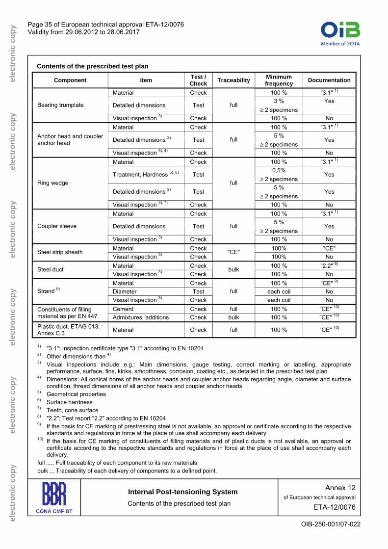
Page 35 of European technical approval ETA-12/0076 Validity from 29.06.2012 to 28.06.2017
OIB-250-001/07-022
elec
tron
ic c
opy
ele
ctro
nic
copy
ele
ctro
nic
copy
ele
ctro
nic
copy
ele
ctro
nic
copy
ele
ctro
nic
copy
Contents of the prescribed test plan
Component Item Test / Check Traceability Minimum
frequency Documentation
Material Check 100 % "3.1" 1) 3 % Yes
Detailed dimensions Test ≥ 2 specimens
Bearing trumplate
Visual inspection 3) Check
full
100 % No Material Check 100 % "3.1" 1)
5 % Detailed dimensions 2) Test
≥ 2 specimens Yes Anchor head and coupler
anchor head
Visual inspection 3), 4) Check
full
100 % No Material Check 100 % "3.1" 1)
0,5% Treatment, Hardness 5), 6) Test
≥ 2 specimens Yes
5 % Detailed dimensions 2) Test
≥ 2 specimens Yes
Ring wedge
Visual inspection 3), 7) Check
full
100 % No Material Check 100 % "3.1" 1)
5 % Detailed dimensions Test
≥ 2 specimens Yes Coupler sleeve
Visual inspection 3) Check
full
100 % No Material Check 100% "CE" Steel strip sheath Visual inspection 3) Check
"CE" 100% No
Material Check 100 % "2.2" 8) Steel duct Visual inspection 3) Check
bulk 100 % No
Material Check 100 % "CE" 9) Diameter Test each coil No Strand 9) Visual inspection 3) Check
full each coil No
Cement Check full 100 % "CE" 10) Constituents of filling material as per EN 447 Admixtures, additions Check bulk 100 % "CE" 10) Plastic duct, ETAG 013, Annex C.3 Material Check full 100 % "CE" 10)
1) "3.1": Inspection certificate type "3.1" according to EN 10204 2) Other dimensions than 4) 3) Visual inspections include e.g.: Main dimensions, gauge testing, correct marking or labelling, appropriate
performance, surface, fins, kinks, smoothness, corrosion, coating etc., as detailed in the prescribed test plan 4) Dimensions: All conical bores of the anchor heads and coupler anchor heads regarding angle, diameter and surface
condition, thread dimensions of all anchor heads and coupler anchor heads. 5) Geometrical properties 6) Surface hardness 7) Teeth, cone surface 8) "2.2": Test report "2.2" according to EN 10204 9) If the basis for CE marking of prestressing steel is not available, an approval or certificate according to the respective
standards and regulations in force at the place of use shall accompany each delivery. 10) If the basis for CE marking of constituents of filling materials and of plastic ducts is not available, an approval or
certificate according to the respective standards and regulations in force at the place of use shall accompany each delivery.
full ..... Full traceability of each component to its raw materials. bulk ... Traceability of each delivery of components to a defined point.
CONA CMF BT
Internal Post-tensioning System Contents of the prescribed test plan
Annex 12 of European technical approval
ETA-12/0076

Page 36 of European technical approval ETA-12/0076 Validity from 29.06.2012 to 28.06.2017
OIB-250-001/07-022
elec
tron
ic c
opy
ele
ctro
nic
copy
ele
ctro
nic
copy
ele
ctro
nic
copy
ele
ctro
nic
copy
ele
ctro
nic
copy
Audit testing
Component Item Test / Check Sampling 2) – Number of components per visit
Material according to specification Test / Check
Detailed dimensions Test
Anchor head, Coupler anchor head
Visual inspection 1) Check
1
Material according to specification Test / Check 2
Treatment Test 2
Detailed dimensions Test 1
Main dimensions, surface hardness Test 5
Ring wedge
Visual inspection 1) Check 5
Material according to specification Test / Check
Detailed dimensions Test Coupler sleeve
Visual inspection 1) Check
1
Single tensile element test
Single tensile element test according to ETAG 013,
Annex E.3 Test 1 Series
1) Visual inspection means, e.g.: main dimensions, gauge testing, correct marking or labelling, appropriate
performance, surface, fins, kinks, smoothness, corrosion protection, corrosion, coating etc., as given in the prescribed test plan.
2) All samples shall be randomly selected and clearly identified.
CONA CMF BT
Internal Post-tensioning System Audit testing
Annex 13 of European technical approval
ETA-12/0076

Page 37 of European technical approval ETA-12/0076 Validity from 29.06.2012 to 28.06.2017
OIB-250-001/07-022
elec
tron
ic c
opy
ele
ctro
nic
copy
ele
ctro
nic
copy
ele
ctro
nic
copy
ele
ctro
nic
copy
ele
ctro
nic
copy
Maximum prestressing and overstressing forces, 05 strand
Maximum prestressing force 1), 3) Maximum overstressing force 1), 2), 3) Force
0.9 · Fp0.1 0.95 · Fp0.1
CONA CMF BT Tendon designation
n05-93 n05-100 n05-93 n05-100
Characteristic tensile strength MPa 1 770 1 860 1 770 1 860 1 770 1 860 1 770 1 860
— — kN kN kN kN kN kN kN kN
02 261 274 281 295 276 289 296 312
03 392 410 421 443 413 433 445 467 n
Number of strands
04 522 547 562 590 551 578 593 623
Maximum prestressing and overstressing forces, 06 strand
Maximum prestressing force 1), 3) Maximum overstressing force 1), 2), 3) Force
0.9 · Fp0.1 0.95 · Fp0.1
CONA CMF BT Tendon designation
n06-140 n06-150 n06-140 n06-150
Characteristic tensile strength MPa 1 770 1 860 1 770 1 860 1 770 1 860 1 770 1 860
— — kN kN kN kN kN kN kN kN
02 392 412 421 443 414 435 445 467
03 589 618 632 664 621 653 667 701 n
Number of strands
04 785 824 842 886 828 870 889 935
1) The given values are maximum values according to EN 1992-1-1. The actual values shall be taken from the
standards and regulations in force at the place of use. Conformity with the stabilisation and crack width criteria in the load transfer test has been verified to a load level of 0.80 ⋅ Fpk.
2) Overstressing is permitted if the force in the prestressing jack can be measured to an accuracy of ± 5 % of the final value of the prestressing force.
3) For strands according to prEN 10138-3, 09.2000, the values shall be multiplied by 0.98 Where
Fpk ...........Characteristic value of maximum force of tendon Fp0.1 .........Characteristic value of 0.1 % proof force of the tendon
CONA CMF BT
Internal Post-tensioning System Maximum prestressing and
overstressing forces
Annex 14 of European technical approval
ETA-12/0076

Page 38 of European technical approval ETA-12/0076 Validity from 29.06.2012 to 28.06.2017
OIB-250-001/07-022
elec
tron
ic c
opy
ele
ctro
nic
copy
ele
ctro
nic
copy
ele
ctro
nic
copy
ele
ctro
nic
copy
ele
ctro
nic
copy
CONA CMF BT
Internal Post-tensioning System Construction stages
Annex 15 of European technical approval
ETA-12/0076

Page 39 of European technical approval ETA-12/0076 Validity from 29.06.2012 to 28.06.2017
OIB-250-001/07-022
elec
tron
ic c
opy
ele
ctro
nic
copy
ele
ctro
nic
copy
ele
ctro
nic
copy
ele
ctro
nic
copy
ele
ctro
nic
copy
BBR VT CONA CMF BT 0205 0305 0405
Strand arrangement
7-wire prestressing steel strand Maximum characteristic tensile strength 1 860 1) in 0.49 0.51 0.49 0.51 0.49 0.51
Nominal diameter mm 12.5 12.9 12.5 12.9 12.5 12.9
Cross sectional area mm2 93 100 93 100 93 100 Tendon
Cross sectional area Ap mm2 186 200 279 300 372 400 Charact. value of maximum force Fpk kN 346 372 519 558 692 744 Charact. value of 0.1 % proof force 2) Fp0.1 kN 304 328 456 492 608 656 Max. prestressing force 2) 0.90 ⋅ Fp0.1 kN 274 295 410 443 547 590 Max. overstressing force 2) 0.95 ⋅ Fp0.1 kN 289 312 433 467 578 623
Minimum concrete strength – Helix – Additional reinforcement – Centre spacing and edge distance Minimum concrete strength
Cube fcm, 0 MPa 21 3) 25 3) 21 3) 25 3) 21 3) 25 3) Cylinder fcm, 0 MPa 17 3) 20 3) 17 3) 20 3) 17 3) 20 3)
Helix – Ribbed reinforcing steel Re ≥ 500 MPa
Outer diameter mm Bar diameter mm Length, approximately mm Pitch mm Number of pitches — Distance E mm
— / — — / — — / — — / — — / — — / —
Additional reinforcement 4) – Ribbed reinforcing steel Re ≥ 500 MPa 5)
Number of stirrups — 4 4 4 4 7 7 Bar diameter mm 8 8 10 10 10 10 Spacing mm 50 50 50 50 50 50 Distance from anchor plate F mm 35 35 35 35 35 35 Minimum outer dimensions A / B mm 160 / 120 160 / 120 190 / 130 160 / 120 320 / 155 320 / 155
Centre spacing and edge spacing Min. centre spacing ac / bc mm 180 / 140 180 / 140 210 / 150 180 / 140 340 / 175 340 / 175 Min. edge distance ae' / be' mm 80 / 60 80 / 60 95 / 65 80 / 60 160 / 80 160 / 80
c …concrete cover 1) Prestressing steel strand with characteristic tensile strength below 1 860 MPa may also be used 2) For strands according to prEN 10138-3, 09.2000, the values shall be multiplied by 0.98 3) Both concrete strength are applicable to tendons with strands of both nominal diameters 12.5 and 12.9 mm 4) Additional reinforcement may be replaced by a rectangular helix of identical diameter and external dimensions, and number of turns
equal to number of stirrups plus one 5) Reinforcing steel with Re ≥ 460 MPa requires a stirrup spacing of 40 mm and one additional stirrup
CONA CMF BT
Internal Post-tensioning System Minimum concrete strength – Helix – Additional reinforcement –
Centre spacing and edge distance
Annex 16 of European technical approval
ETA-12/0076
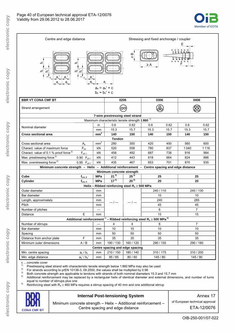
Page 40 of European technical approval ETA-12/0076 Validity from 29.06.2012 to 28.06.2017
OIB-250-001/07-022
elec
tron
ic c
opy
ele
ctro
nic
copy
ele
ctro
nic
copy
ele
ctro
nic
copy
ele
ctro
nic
copy
ele
ctro
nic
copy
BBR VT CONA CMF BT 0206 0306 0406
Strand arrangement
7-wire prestressing steel strand Maximum characteristic tensile strength 1 860 1) in 0.6 0.62 0.6 0.62 0.6 0.62
Nominal diameter mm 15.3 15.7 15.3 15.7 15.3 15.7
Cross sectional area mm2 140 150 140 150 140 150 Tendon
Cross sectional area Ap mm2 280 300 420 450 560 600 Charact. value of maximum force Fpk kN 520 558 780 837 1 040 1 116 Charact. value of 0.1 % proof force 2) Fp0.1 kN 458 492 687 738 916 984 Max. prestressing force 2) 0.90 ⋅ Fp0.1 kN 412 443 618 664 824 886 Max. overstressing force 2) 0.95 ⋅ Fp0.1 kN 435 467 653 701 870 935
Minimum concrete strength – Helix – Additional reinforcement – Centre spacing and edge distance Minimum concrete strength
Cube fcm, 0 MPa 21 3) 25 3) 25 25 Cylinder fcm, 0 MPa 17 3) 20 3) 20 20
Helix – Ribbed reinforcing steel Re ≥ 500 MPa
Outer diameter mm 240 / 110 240 / 130 Bar diameter mm 10 10 Length, approximately mm 240 285 Pitch mm 45 45 Number of pitches — 6 7 Distance E mm
— / — — / —
15 15 Additional reinforcement 4) – Ribbed reinforcing steel Re ≥ 500 MPa 5)
Number of stirrups — 4 4 6 7 Bar diameter mm 10 10 10 10 Spacing mm 50 50 50 50 Distance from anchor plate F mm 35 35 35 35 Minimum outer dimensions A / B mm 190 / 130 160 / 120 290 / 155 290 / 180
Centre spacing and edge spacing Min. centre spacing ac / bc mm 210 / 150 180 / 140 310 / 175 310 / 200 Min. edge distance ae' / be' mm 95 / 65 80 / 60 145 / 80 145 / 90
c …concrete cover 1) Prestressing steel strand with characteristic tensile strength below 1 860 MPa may also be used 2) For strands according to prEN 10138-3, 09.2000, the values shall be multiplied by 0.98 3) Both concrete strength are applicable to tendons with strands of both nominal diameters 15.3 and 15.7 mm 4) Additional reinforcement may be replaced by a rectangular helix of identical diameter and external dimensions, and number of turns
equal to number of stirrups plus one 5) Reinforcing steel with Re ≥ 460 MPa requires a stirrup spacing of 40 mm and one additional stirrup
CONA CMF BT
Internal Post-tensioning System Minimum concrete strength – Helix – Additional reinforcement –
Centre spacing and edge distance
Annex 17 of European technical approval
ETA-12/0076
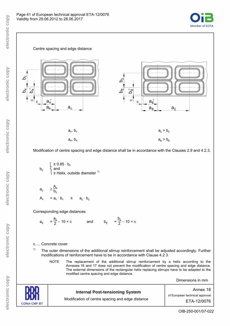
Page 41 of European technical approval ETA-12/0076 Validity from 29.06.2012 to 28.06.2017
OIB-250-001/07-022
elec
tron
ic c
opy
ele
ctro
nic
copy
ele
ctro
nic
copy
ele
ctro
nic
copy
ele
ctro
nic
copy
ele
ctro
nic
copy
Centre spacing and edge distance
ac, bc ac > bc ae, be ae > be
Modification of centre spacing and edge distance shall be in accordance with the Clauses 2.9 and 4.2.3.
bc ⎩⎨⎧ ≥ 0.85 ⋅ bc
and ≥ Helix, outside diameter 1)
ac ≥ Acbc
Ac = ac · bc ≤ ac · bc
Corresponding edge distances
ae = ac
2 − 10 + c and be = bc
2 − 10 + c
c..... Concrete cover 1) The outer dimensions of the additional stirrup reinforcement shall be adjusted accordingly. Further
modifications of reinforcement have to be in accordance with Clause 4.2.3. NOTE The replacement of the additional stirrup reinforcement by a helix according to the
Annexes 16 and 17 does not prevent the modification of centre spacing and edge distance. The external dimensions of the rectangular helix replacing stirrups have to be adapted to the modified centre spacing and edge distance.
Dimensions in mm
CONA CMF BT
Internal Post-tensioning System Modification of centre spacing and edge distance
Annex 18 of European technical approval
ETA-12/0076

Page 42 of European technical approval ETA-12/0076 Validity from 29.06.2012 to 28.06.2017
OIB-250-001/07-022
elec
tron
ic c
opy
ele
ctro
nic
copy
ele
ctro
nic
copy
ele
ctro
nic
copy
ele
ctro
nic
copy
ele
ctro
nic
copy
Dimensions in mm
CONA CMF BT
Internal Post-tensioning System Free tendon layout with monostrands or VT CMM Bands –
Tendon CONA CMF BT 0405 and 0406
Annex 19 of European technical approval
ETA-12/0076

Page 43 of European technical approval ETA-12/0076 Validity from 29.06.2012 to 28.06.2017
OIB-250-001/07-022
elec
tron
ic c
opy
ele
ctro
nic
copy
ele
ctro
nic
copy
ele
ctro
nic
copy
ele
ctro
nic
copy
ele
ctro
nic
copy
Installation of tendons with prestressing steel strands other than monostrands 1) Preparatory work
The components of the prestressing kit shall be stored in such a way as to avoid any damage or corrosion.
2) Anchorage recesses Adequate clearance to accommodate and to use the prestressing jack shall be ensured, see also the Clauses 2.1.5 and 4.2.2.
3) Fixing the bearing trumplates Two slots are provided to fix the bearing trumplates to the formwork. The trumpet is screwed into the bearing trumplate. The helix is either welded to the bearing trumplate, see also Clause 4.8, or placed by fixing it to the existing reinforcement.
4) Placing of sheaths The sheaths are placed on supports with spacing according to Clause 2.5 and minimum radii of curvature according to Clause 2.4. The sheaths have to be connected in a water-proof way. The sheaths shall be supported such that any movement is prevented.
The same applies to prefabricated tendons.
5) Installation of tensile elements – prestressing steel The prestressing steel is pushed or pulled into the sheath before or after concreting the structure.
6) Installation of inaccessible fixed anchorages After passing the strands through the anchor head, they are anchored individually in the cones by means of ring wedges. After the assembly the wedges are secured with springs or a wedge retaining plate. An alternative is pre-locking each individual strand with ~ 0.5 · Fpk and applying a wedge retaining plate.
7) Checking the tendons before concreting Before concreting the structure the fixation and position of the entire tendon have to be checked and corrected if necessary. The sheaths shall be checked for any damage.
8) Assembly of anchor head / coupler anchor head 1.BA After passing the strands through the anchor head, they are anchored individually in the cones by means of ring wedges. The same applies for the coupler anchor head 1.BA of a fixed coupler in the first construction stage.
9) Prestressing At the time of stressing the mean concrete compressive strength shall be at least according to Table 4 and Clause 2.8. Stressing and possible wedging has to be carried out with a suitable prestressing jack and in accordance with Clause 4.4.
The elongations of the tendon and the prestressing forces shall be checked and recorded systematically during the stressing operation.
Restressing of the tendons is allowed in accordance with Clause 4.5.
10) Installation of fixed coupler anchor head 2.BA The function of the fixed coupler is to connect two tendons, whereas the first tendon is stressed before the second tendon is installed and stressed.
The coupler anchor head H, 2.BA is assembled with ring wedges and a wedge retaining plate. It is connected to the already tensioned coupler anchor head H, 1.BA by means of a threaded coupler sleeve.
11) Assembly of movable coupler The movable coupler serves to lengthen unstressed tendons. The axial movement during stressing is ensured by a coupler sheathing box suitable to the expected elongation at the position of the coupler.
The assembly of the coupler anchor heads is performed in accordance with the Points 8) and 10) and Clause 2.1.4.
12) Filling of tendons Grout shall be injected through the inlet holes until it escapes from the outlet tubes with the same consistency. All vents and grouting inlets shall be sealed immediately after grouting, see also Clause 4.7.
Grease or wax has to be injected in accordance with ETAG 013 and the recommendations of the supplier.
More detailed information on installation can be obtained from the ETA holder.
CONA CMF BT
Internal Post-tensioning System Description of installation of bonded and unbonded tendons
other than monostrand tendons
Annex 20 of European technical approval
ETA-12/0076

Page 44 of European technical approval ETA-12/0076 Validity from 29.06.2012 to 28.06.2017
OIB-250-001/07-022
elec
tron
ic c
opy
ele
ctro
nic
copy
ele
ctro
nic
copy
ele
ctro
nic
copy
ele
ctro
nic
copy
ele
ctro
nic
copy
Installation of tendons with monostrands or VT CMM Bands 1) Preparatory work
The components of the prestressing kit shall be stored in such a way as to avoid any damage or corrosion.
2) Anchorage recesses Adequate clearance to accommodate and to use the prestressing jack shall be ensured, see also the Clauses 2.1.5 and 4.2.2.
3) Fixing the bearing trumplate Two slots are provided to fix the bearing trumplate to the formwork. The transition pipes are pushed into the anchor head and the helix is either welded to the bearing trumplate, see also Clause 4.8, or placed by fixing it to the existing reinforcement.
4) Placing of monostrands or VT CMM Bands The strands are placed on supports with spacing according to Clause 2.5 and minimum radii of curvature according to Clause 2.4. The strands shall be supported such as any movement is prevented.
The same applies for prefabricated tendons.
Installation in free tendon layout shall be according to Clause 2.5.2 and Annex 19.
5) Installation of inaccessible fixed anchorages VT CMM Band are cut longitudinally to separate the individual strands. This is not applicable to monostrands. Removal of the PE-sheathing at the end and inserting the felt sealing on each single strand in the region of the transition pipe. The same applies to accessible fixed anchorages and stressing anchorages. After pushing the strands through the anchor head the removed PE-sheathing is placed back to protect the excess strand length of the stressing anchorage.
The strands passing through the anchor head of the inaccessible fixed anchorage are anchored individually in the cones by means of ring wedges. After assembly the wedges are secured with springs or a wedge retaining plate. An alternative is pre-locking each individual strand with ~ 0.5 · Fpk and applying a wedge retaining plate.
The protection cap is filled with grease and connected to the head.
6) Similar procedures In accordance with the installation of tendons with prestressing steel strand other than monostrands, see Annex 20, the following procedures are applied: - Checking of the tendons before concreting - Assembly of anchor head / coupler anchor head 1.BA - Prestressing - Installation of fixed coupler anchor head 2.BA
7) Fixed and stressing coupler type FH, SH 1) The couplers type FH and SH can be executed with monostrand and VT CMM Band tendons.
8) Filling of anchorages Stressing anchorages, accessible fixed anchorages, coupler anchorages 1.BA, and finally installed fixed couplers shall be filled with grease and protected with a cap in accordance with Point 5). The latter does not apply to couplers.
More detailed information on installation can be obtained from the ETA holder.
1) The movable coupler type BH cannot be executed with monostrands or VT CMM Bands
CONA CMF BT
Internal Post-tensioning System Description of installation of monostrands or
VT CMM Bands
Annex 21 of European technical approval
ETA-12/0076

Page 45 of European technical approval ETA-12/0076 Validity from 29.06.2012 to 28.06.2017
OIB-250-001/07-022
elec
tron
ic c
opy
ele
ctro
nic
copy
ele
ctro
nic
copy
ele
ctro
nic
copy
ele
ctro
nic
copy
ele
ctro
nic
copy
Sheathing base material specification for monostrand / VT CMM Band
Characteristics Test method / Standard Acceptance Criteria
Melt index ISO 1133 (10 minutes at 2.16 kg)
≥ 0.25 g
Density DIN 53479 ≥ 0.95 g/cm3 Carbon black
- Content - Dispersion - Distribution
ISO 6964 ISO 4437 ISO 4437
2.3 +/- 0.3 % Index max. C2 Index max. 3
Tensile strength (23 °C) EN ISO 527-2 ≥ 22 MPa 1) Elongation
- at 23 °C - at - 20 °C
EN ISO 527-2 > 600 % 1)
> 350 % 1) Thermal stability ISO/TR 10837 ≥ 20 minutes at 210 °C in O2 without
degradation (oxygen induction time) 1) Standardised specimen according to ISO 1 BA, loading speed 100 mm/minute
Manufactured sheathing specification for monostrand / VT CMM Band Characteristics Test method /
Standard Acceptance Criteria
Tensile strength at 23 °C EN ISO 527-2 ≥ 18 MPa 1) Elongation
- at 23 °C - at - 20 °C
EN ISO 527-2 EN ISO 527-2
≥ 450 % 1)
≥ 250 % 1) Surface of sheathing No visual damage
No bubbles No traces of filling material visible
Environmental stress cracking NF C 32-060 No cracking after 72 hours in a tensio-active liquid at 50 °C
Temperature resistance Variation of tensile strength at 23 °C after conditioning for 3 days at 100 °C Variation of elongation at 23 °C after conditioning for 3 days at 100 °C
EN ISO 527-2 EN ISO 527-2
≤ 25 % ≤ 25 %
Resistance to externally applied agents: Mineral oil Acids Bases Solvents Salt spray
EN ISO 175 Variation of tensile strength ≤ 25 % Variation of elongation ≤ 25 % Variation of volume ≤ 5 %
Sheathing minimum thickness prEN 496 ≥ 1.0 mm 2) 1) Standardised specimen according to ISO 1 BA, loading speed 100 mm/minute 2) The actual value has to conform to standards and requirements in force at the place of use.
CONA CMF BT
Internal Post-tensioning System Specification
Annex 22 of European technical approval
ETA-12/0076

Page 46 of European technical approval ETA-12/0076 Validity from 29.06.2012 to 28.06.2017
OIB-250-001/07-022
elec
tron
ic c
opy
ele
ctro
nic
copy
ele
ctro
nic
copy
ele
ctro
nic
copy
ele
ctro
nic
copy
ele
ctro
nic
copy
Monostrand / VT CMM Band specification Characteristics Test method / Standard Acceptance Criteria
Impact resistance Clause C.1.3.2.1 1) No tear or penetration of sheathing Friction between sheathing and strand Clause C.1.3.2.2 1) ≤ 60 N/m Squeezing
- Transverse deformation under load
- Residual transverse deformation after removal of load
Clause C.1.3.2.3 1)
≤ 3 % ≤ 2.5 %
Leak tightness Clause C.1.3.2.3 1) No water leaking through specimen 1) In ETAG 013, June 2002
Grease specification of the monostrand / of the VT CMM Band Characteristics Test method / Standard Acceptance Criteria
Cone penetration, 60 strokes (1/10 mm) ISO 2137 250 - 300
Dropping point ISO 2176 ≥ 150 °C
Oil separation at 40 °C DIN 51817 at 72 hours ≤ 2.5 % at 7 days ≤ 4.5 %
Oxidation stability DIN 51808 100 hours at 100°C ≤ 0.06 MPa 1 000 hours at 100°C ≤ 0.2 MPa
Corrosion protection 168 hours at 35 °C 168 hours at 35 °C
NF X41-002 (salt spray) 1)
NF X41-002 (distilled water spray) 1)
Pass No corrosion
Corrosion test DIN 51802 Grade 0
Content of aggressive elements Cl-, S2-, NO3
-
SO42-
NF M07-023 2)
NF M07-023 2) ≤ 50 ppm (0.005 %) ≤ 100 ppm (0.010 %)
1) Test sample consists of a structural steel plate S355 with a surface roughness comparable to the prestressing wire and strand. The plate is covered with a layer of grease of a maximum thickness corresponding to the declared mass of the filling material per linear meter (based on nominal strand diameter).
2) Applied accordingly to grease.
Grease properties after monostrand / VT CMM Band manufacturing Characteristics Test method / Standard Acceptance Criteria
Dropping point - variation during monostrand
manufacturing
ISO 2176 ≤ 10 %
Oil separation variation during monostrand
manufacturing DIN 51808 at 72 hours ≤ 3.0 %
at 7 days ≤ 5.0 %
CONA CMF BT
Internal Post-tensioning System Specification
Annex 23 of European technical approval
ETA-12/0076

Page 47 of European technical approval ETA-12/0076 Validity from 29.06.2012 to 28.06.2017
OIB-250-001/07-022
elec
tron
ic c
opy
ele
ctro
nic
copy
ele
ctro
nic
copy
ele
ctro
nic
copy
ele
ctro
nic
copy
ele
ctro
nic
copy
Seven-wire strands according to prEN 10138-3 1)
Steel name Y1860S7
Tensile strength fpk MPa 1 860
Diameter d mm 12.5 12.9 15.3 15.7
Nominal cross-sectional area Ap mm2 93 100 140 150
Nominal mass per metre m kg/m 0.726 3 0.781 1.093 1.172
Permitted deviation from nominal mass % ± 2
Characteristic value of maximum force Fpk kN 173 186 260 279
Maximum value of maximum force Fm,max kN 199 214 299 321
Characteristic value of 0.1% proof force 2) Fp0.1 kN 152 164 229 246
Minimum elongation at max. force, L0 ≥ 500 mm Agt % 3.5
Modulus of elasticity Ep MPa 195 000 3)
Steel name Y1770S7
Tensile strength fpk MPa 1 770
Diameter d mm 12.5 12.9 15.3 15.7
Nominal cross-sectional area Ap mm2 93 100 140 150
Nominal mass per metre m kg/m 0.726 3 0.781 1.093 1.172
Permitted deviation from nominal mass % ± 2
Characteristic value of maximum force Fpk kN 165 177 248 266
Maximum value of maximum force Fm,max kN 190 204 285 306
Characteristic value of 0.1% proof force 2) Fp0.1 kN 145 156 218 234
Minimum elongation at max. force, L0 ≥ 500 mm Agt % 3.5
Modulus of elasticity Ep MPa 195 000 3) 1) Suitable strands according to standards and regulations in force at the place of use may also be used. 2) For strands according to prEN 10138-3, 09.2000, the value shall be multiplied by 0.98 3) Standard value
CONA CMF BT
Internal Post-tensioning System Strand specification
Annex 24 of European technical approval
ETA-12/0076

Page 48 of European technical approval ETA-12/0076 Validity from 29.06.2012 to 28.06.2017
OIB-250-001/07-022
elec
tron
ic c
opy
ele
ctro
nic
copy
ele
ctro
nic
copy
ele
ctro
nic
copy
ele
ctro
nic
copy
ele
ctro
nic
copy
Reference documents
Guideline for European Technical Approval ETAG 013, 06.2002 Guideline for European Technical Approval of Post-Tensioning Kits for
Prestressing of Structures
Standards EN 206-1, 12.2000 EN 206-1/A1, 07.2004 EN 206-1/A2, 06.2005
Concrete - Part 1: Specification, performance, production and conformity
EN 445, 10.2007 Grout for prestressing tendons - Test methods EN 446, 10.2007 Grout for prestressing tendons - Grouting procedures EN 447, 10.2007 Grout for prestressing tendons - Basic requirements EN 523, 08.2003 Steel strip sheaths for prestressing tendons - Terminology, requirements, quality
control EN 1561, 10.2011 Founding - Grey cast irons EN 1563, 12.2011 Founding - Spheroidal graphite cast irons EN 1992-1-1, 12.2004 EN 1992-1-1/AC, 11.2010
Eurocode 2: Design of concrete structures - Part 1-1: General rules and rules for buildings
EN 10025-2, 11.2004 EN 10025-2/AC, 06.2005
Hot rolled products of structural steels - Part 2: Technical delivery conditions for non-alloy structural steels
EN 10083-1, 08.2006 Steels for quenching and tempering - Part 1: General technical delivery conditions
EN 10083-2, 08.2006 Steels for quenching and tempering - Part 2: Technical delivery conditions for non alloy steels
EN 10084, 04.2008 Case hardening steels - Technical delivery conditions EN 10204, 10.2004 Metallic products - Types of inspection documents EN 10210-1, 04.2006 Hot finished structural hollow sections of non-alloy and fine grain steels -
Part 1: Technical delivery conditions EN 10216-1, 05.2002 EN 10216-1/A1, 03.2004
Seamless steel tubes for pressure purposes - Technical delivery conditions -Part 1: Non-alloy steel tubes with specified room temperature properties
EN 10217-1, 05.2002 EN 10217-1/A1, 01.2005
Welded steel tubes for pressure purposes - Technical delivery conditions -Part 1: Non-alloy steel tubes with specified room temperature prope
EN 10219-1, 04.2006 Cold formed welded structural hollow sections of non-alloy and fine grain steels -Part 1: Technical delivery conditions
EN 10255+A1, 04.2007 Non-alloy steel tubes suitable for welding and threading - Technical delivery conditions
EN 10270-1, 10.2011 Steel wire for mechanical springs - Part 1: Patented cold drawn unalloyed steel wire
EN 10277-2, 03.2008 Bright steel products - Technical delivery conditions - Part 2: Steels for general engineering purposes
CONA CMF BT
Internal Post-tensioning System Reference documents
Annex 25 of European technical approval
ETA-12/0076

Page 49 of European technical approval ETA-12/0076 Validity from 29.06.2012 to 28.06.2017
OIB-250-001/07-022
elec
tron
ic c
opy
ele
ctro
nic
copy
ele
ctro
nic
copy
ele
ctro
nic
copy
ele
ctro
nic
copy
ele
ctro
nic
copy
EN 10305-5, 01.2010 Steel tubes for precision applications - Technical delivery conditions -
Part 5: Welded and cold sized square and rectangular tubes EN 12201-1, 09.2011 Plastic piping system for water supply - polyethylene (PE) - Part 1: General EN ISO 175, 03.2000 Plastics - Methods of test for the determination of the effects of immersion in
liquid chemicals EN ISO 527-2, 05.1996 Plastics - Determination of tensile properties - Part 2: Test conditions for
moulding and extrusion plastics EN ISO 1872-1, 05.1999 Plastics - Polyethylene (PE) moulding and extrusion materials -
Part 1: Designation system and basis for specifications EN ISO 1874-1, 11.2010 Plastics - Polyamide (PA) moulding and extrusion materials - Part 1: Designation
system and basis for specification prEN 496, 05.1991 Plastics piping systems - plastics pipes and fittings - measurements of
dimensions and visual inspection of surfaces prEN 10138-3, 08.2009 Prestressing steels - Part 3: Strand prEN 10138-3, 09.2000 Prestressing steels - Part 3: Strand CWA 14646, 01.2003 Requirements for the installation of post-tensioning kits for prestressing of
structures and qualification of the specialist company and its personnel ISO 1133, 01.1997 Plastics - Determination of the melt mass-flow rate (MFR) and the melt volume-
flow rate (MVR) of thermoplastics ISO 2137, 11.1985 Petroleum products - Lubricating grease and petrolatum - Determination of cone
penetration ISO 2176, 03.1995 Petroleum products - Lubricating grease - Determination of dropping point ISO 4437, 06.2007 Buried polyethylene (PE) pipes for the supply of gaseous fuels - Metric series -
Specifications ISO 6964, 12.1986 Polyolefin pipes and fittings - Determination of carbon black content by
calcination and pyrolysis - Test method and basic specification ISO/TR 10837, 07.1991 Determination of the thermal stability of polyethylene (PE) for use in gas pipes
and fittings NF C32-060, 05.1996 Polyolefin insulation and sheath for communication cables NF M07-023, 02.1969 Liquid fuels - Determination of chlorides in crude petroleum and petroleum
products NF X41-002, 08.1975 Protection against physical, chemical and biological agents - Salt spray test DIN 51802, 04.1990 Testing lubricating greases for their corrosion-inhibiting properties by the SKF
Emcor method DIN 51808, 01.1978 Testing of lubricants - Determination of oxidation stability of greases, oxygen
method DIN 51817, 04.1998 Testing of lubricants - Determination of oil separation from greases under static
conditions DIN 53479, 10.1991 Testing of plastics and elastomers - Determination of density
CONA CMF BT
Internal Post-tensioning System Reference documents
Annex 26 of European technical approval
ETA-12/0076


Empty page for adding notes

Empty page for adding notes

Empty page for adding notes

Co
pyr
ight
BB
R V
T In
tern
atio
nal 0
9.20
12
BBR VT International LtdBahnstrasse 23CH-8603 Schwerzenbach (ZH)Switzerland
Tel +41 44 806 80 60Fax +41 44 806 80 50
BBR VT International LtdTechnical Headquarters and Business Development CentreSwitzerland


