Bayfield Infrastructure Design Standards 4.18
35
TOWN OF BAYFIELD INFRASTRUCTURE DESIGN STANDARDS Town of Bayfield P.O Box 80 1199 US Highway 160B Bayfield, CO 81122 ADOPTED BY ORDINANCE NO. 408 May 24, 2017 Phone: 970-884-9544 www.bayfieldgov.org Fax: 970-884-2195
Transcript of Bayfield Infrastructure Design Standards 4.18

TOWN OF BAYFIELD
INFRASTRUCTURE DESIGN STANDARDS
Town of Bayfield P.O Box 80
1199 US Highway 160B Bayfield, CO 81122
ADOPTED BY ORDINANCE NO. 408
May 24, 2017
Phone: 970-884-9544 www.bayfieldgov.org Fax: 970-884-2195
Ordinance #408 i May 24 , 2017
TABLE OF CONTENTS TOWN OF BAYFIELD ........................................................................................................ i 1.0 GENERAL REQUIREMENTS ...................................................................................... 1
1.1 SCOPE ...............................................................................................................................1 1.2 TERMS ...............................................................................................................................1
1.2.1 Requirements ..........................................................................................................1 1.2.2 Approval .................................................................................................................1 1.2.3 Commencement of Construction ............................................................................1 1.2.4 Final Acceptance of Public Improvements ............................................................2 1.2.5 Professional Fees ....................................................................................................2
1.3 REQUIRED SUBMITTALS ..............................................................................................2 1.3.1 Plans and Specifications .........................................................................................2 1.3.2 Reports ...................................................................................................................5 1.3.3 Plan Revisions ........................................................................................................7 1.3.4 Record Drawings ....................................................................................................7
2.0 STREETS ........................................................................................................................ 9 2.1 GENERAL .........................................................................................................................9
2.1.1 Description .............................................................................................................9 2.2 DESIGN CRITERIA ..........................................................................................................9
2.2.1 Street Classification ................................................................................................9 2.2.2 Street Design Criteria .............................................................................................9 2.2.3 Street Design ..........................................................................................................10 2.2.4 Intersection Design .................................................................................................12 2.2.5 Secondary Access Requirements ...........................................................................12 2.2.6 Pavement Design ....................................................................................................13 2.2.7 Curb & Gutter .........................................................................................................13 2.2.8 Sidewalks ...............................................................................................................14 2.2.9 Pedestrian and Bike Paths ......................................................................................14 2.2.10 Driveways ...............................................................................................................14 2.2.11 Bicycle Lanes .........................................................................................................15 2.2.12 Street Lighting ........................................................................................................15
3.0 DOMESTIC WATER SYSTEM .................................................................................... 16 3.1 GENERAL .........................................................................................................................16
3.1.1 Description .............................................................................................................16 3.2 DESIGN CRITERIA ..........................................................................................................16
3.2.1 Distribution System Layout ...................................................................................16 3.2.2 Water Main Size .....................................................................................................16 3.2.3 Depth ......................................................................................................................16 3.2.4 Valves .....................................................................................................................17 3.2.5 Fire Hydrants ..........................................................................................................17 3.2.6 Pipe Joint Restraint .................................................................................................17 3.2.7 Water Services ........................................................................................................17 3.2.8 Underground Warning Tape and Tracer Wire .......................................................18 3.2.9 Separation of Water and Other Utilities .................................................................18 3.2.10 Access to Facilities .................................................................................................18
4.0 SANITARY SEWER SYSTEM ..................................................................................... 20
Ordinance #408 ii May 24 , 2017
4.1 GENERAL .........................................................................................................................20 4.1.1 Description .............................................................................................................20
4.2 DESIGN CRITERIA ..........................................................................................................20 4.2.1 Collection System Layout ......................................................................................20 4.2.2 Sewer Main Size .....................................................................................................21 4.2.3 Sewer Main Depth ..................................................................................................21 4.2.4 Gravity Sewer Line Slopes .....................................................................................22 4.2.5 Force Main Grades .................................................................................................22 4.2.6 Force Main Valves .................................................................................................22 4.2.7 Force Main Pipe Joint Restraint .............................................................................23 4.2.8 Sewer Taps and Services ........................................................................................23 4.2.9 Oil, Grease, And Grit Interceptors .........................................................................23 4.2.10 Sampling and Pretreatment of High-Strength Wastewater ....................................24 4.2.11 Underground Warning Tape and Tracer Wire .......................................................24 4.2.12 Separation of Sanitary Sewer and Water Mains .....................................................24 4.2.13 Access to Facilities .................................................................................................25
5.0 STORM DRAINAGE SYSTEM .................................................................................... 26 5.1 GENERAL .........................................................................................................................26 5.2 DESIGN CRITERIA ..........................................................................................................26
5.2.1 Design Storms ........................................................................................................26 5.2.2 Storm Water Runoff Analysis ................................................................................26 5.2.3 Storm Drainage Design Analysis ...........................................................................28 5.2.4 Storm Drainage Design Requirements ...................................................................29 5.2.5 Other Design Considerations .................................................................................31 5.2.6 Detention Pond Certifications ................................................................................32

1.0 GENERAL REQUIREMENTS
Ordinance #408 1 May 24, 2017
1.0 GENERAL REQUIREMENTS
1.1 SCOPE These Infrastructure Design Standards and submittal requirements are applicable to all Town of Bayfield public infrastructure improvement projects and all aspects of private development projects that impact public property or infrastructure or adjacent properties. Specific private development improvements that shall meet these design standards and submittal requirements include, at a minimum: roadway infrastructure, driveway accesses, water and sewer services, and grading and storm water infrastructure. In addition, all public infrastructure and private development projects shall meet all other applicable Town of Bayfield Land Use Code requirements, Town of Bayfield Construction Specifications, all building and fire codes adopted by the Town of Bayfield, all applicable State, Federal, and County regulations and requirements, all other utility provider requirements, and all irrigation company requirements. Where any of these requirements may conflict, the more restrictive requirement shall apply. Design issues not addressed in these Design Standards shall be reviewed and resolved on a case-by-case basis when brought to the Town’s attention. Projects that are unable to meet one or more design standards shall also be reviewed and resolved on a case-by-case basis when brought to the Town’s attention. Requests for exceptions to these requirements shall be in writing; shall include reference to the specific section of the standards; and shall provide detailed explanations, necessary engineering data and plans, and proposed alternative to the standard(s).
1.2 TERMS 1.2.1 Requirements All construction of public and applicable private improvements within the Town of Bayfield shall be completed in accordance with these Infrastructure Design Standards and the Town of Bayfield Construction Specifications. The words “shall” and “must” indicate requirements that must be adhered to; the word “may” or “recommend” indicates standards that are allowed or recommended, but not required. Reference to Standard Details refers to the standard detail drawings included in the Town of Bayfield Construction Specifications. The Town of Bayfield shall have the authority to make all interpretations of the requirements of these standards. 1.2.2 Approval All final plans, specifications, and engineering reports related to the requirements of these standards shall be stamped and signed by a Colorado Licensed Professional Engineer, or Architect, if applicable; preliminary plans, specifications, and reports may be submitted for review without being stamped by the Engineer or Architect, but should be stamped “Preliminary”. Approval of the plans, specifications, and engineering reports by the Town of Bayfield will be provided in writing after all design issues have been addressed. 1.2.3 Commencement of Construction Generally, construction shall not commence prior to approval by the Town of Bayfield of the final plans, specifications, and other required submittals. In limited cases, commencement of construction may be approved by the Town of Bayfield while minor design issues that don’t impact initial construction are being resolved with the Design Engineer. Any construction completed prior to final approval that does not match the approved final plans is the responsibility of the developer to correct.

1.0 GENERAL REQUIREMENTS
Ordinance #408 2 May 24, 2017
1.2.4 Final Acceptance of Public Improvements Final acceptance of public improvements shall be given in writing by the Town of Bayfield and shall be contingent upon:
1. Submittal of approved Record Drawings for public infrastructure projects. Record Drawing requirements are defined in Section 1.3.4 of these Standards.
2. Submittal of passing test results required as part of the Town of Bayfield Construction Specifications.
3. Construction phase inspections and final inspection by the Town of Bayfield.
1.2.5 Professional Fees The Developer/Contractor shall pay the Town the actual cost to the Town for engineering, planning, surveying, and legal services rendered in connection with the review of the requisite permit. The Developer/Contractor, upon submission of the applicable permit, must deposit a certified check in the amount determined by the Board of Trustees or its designee. The amount of the deposit shall be based upon the type of development, size of development, and the anticipated impact of the development on the Town. The deposit shall serve as security for payment of the actual cost to the Town in providing the services described above. Any remaining amounts shall not be refunded until after the project has been inspected, approved, and – if necessary – record drawings filed.
1.3 REQUIRED SUBMITTALS 1.3.1 Plans and Specifications A. General Requirements:
1. Plans and specifications are to be prepared based on these and other applicable design requirements. All design work is to be prepared under the direction of, and stamped and signed by, a Colorado Licensed Professional Engineer or Architect, as applicable. Plans are to be completed in sufficient detail to facilitate review and to clearly describe the existing conditions and proposed development of the project in its entirety. The required plans and specifications will depend upon the size, nature, and complexity of the project. Reference to the Town of Bayfield Construction Specifications on the plans or in the specifications is acceptable but relevant Town standard detail drawings shall be included on the plans for convenience during construction.
2. All plans involving public infrastructure shall be tied to the North American Datum of 1983 (NAD 83) and North American Vertical Datum of 1988 (NAVD 88) for ease in incorporating infrastructure plans into the Town’s infrastructure base maps.
3. Profiles shall be shown for street designs, as well as gravity sanitary sewer and storm drain designs. Other utilities that are parallel to profiled utilities and at, or near, a standardized depth, such as water, sewer force main, gas, etc., do not have to be shown on profiles, but may be included to provide clarity; all utility crossings shall be shown on profiles. Legibility shall be considered when showing street design data and multiple utilities on a single profile.
4. Line types and weights shall be used to clearly identify the features represented on the plans. Existing features shall be represented with lighter weight lines (existing utilities) or dashed lines (existing contour lines); proposed features shall be represented with heavier weight lines (proposed utilities) or solid lines (proposed contour lines). Color shall not be relied upon to distinguish utilities or other features. Utility line types shall use the standardized letters shown in Table 1.1 to represent the utilities on plan views.
5. All plan sheets showing streets, utilities, site layout, etc., shall show a north arrow and a graphic and written scale (with associated sheet size). Scales for plan sheets shall be standard engineering scales, i.e., 1 inch equals 10, 20, 30, 40, 50, or 60 feet, as appropriate, to be able to clearly show the proposed improvements. The vertical scale of profiles shall be exaggerated at an appropriate scale to provide clarity, generally with 2-ft grid intervals.

1.0 GENERAL REQUIREMENTS
Ordinance #408 3 May 24, 2017
6. Existing grade contours shall be shown at a minimum of 2-foot intervals; very flat sites shall show contours at 1-foot intervals. The contour interval of proposed grades shall match the existing grade contours.
7. The preferred size for plan review submittals is 11” x 17”, plotted to scale. If the reduced size inhibits legibility, 24” x 36” sheets shall be submitted. Electronic submittal of review plans in portable document format (pdf) is allowed if they are set up to print to scale at 11” x 17”. Stamped final plans shall be 24” x 36”.
Table 1.1 Standardized Utility Line Types Utility Line Representation
Water main WWater service wsSanitary sewer main SSanitary sewer service ssSewer force main FMStorm drain SDTelephone TTelephone service tsElectric – overhead OHEElectric – underground UGEElectric service esNatural gas main GNatural gas service gs
B. Plan Requirements:
1. General: The plan organization described below is general in nature. The actual location of the relevant information may vary from that described below, as long as the plans present the information in a logical and organized manner.
2. Cover and Index Sheets: Plans shall include a cover sheet showing the project title, project location map, and stamp and signature of the Engineer or Architect, date of the plans, and revision numbers and descriptions. A sheet index may be included on the cover sheet for small plan sets or may be included on an index sheet for larger plan sets. A sheet layout plan or sheet key map showing the layout of plan sheets shall be provided on multiple-sheet street or utility improvement plan sets.
3. Street or Road Plans shall show at a minimum: a. Roadway centerline horizontal geometry with stationing. b. Roadway centerline vertical geometry with stationing. c. Location and widths of right-of-way. d. Existing contour and finished grade contour lines. e. Toes of all slopes. f. Centerline stationing at no more than 100-foot intervals. g. Stationing and elevations for beginnings, ends, intersection points, and high or low points of
vertical curves. h. Dimensions of all road elements, curbs, gutters, utilities, easements and other structures. i. Intersection sight triangles with height restrictions identified. j. Location (station and offset) and construction details for all structures, bridges, box culverts,
etc.
1.0 GENERAL REQUIREMENTS
Ordinance #408 4 May 24, 2017
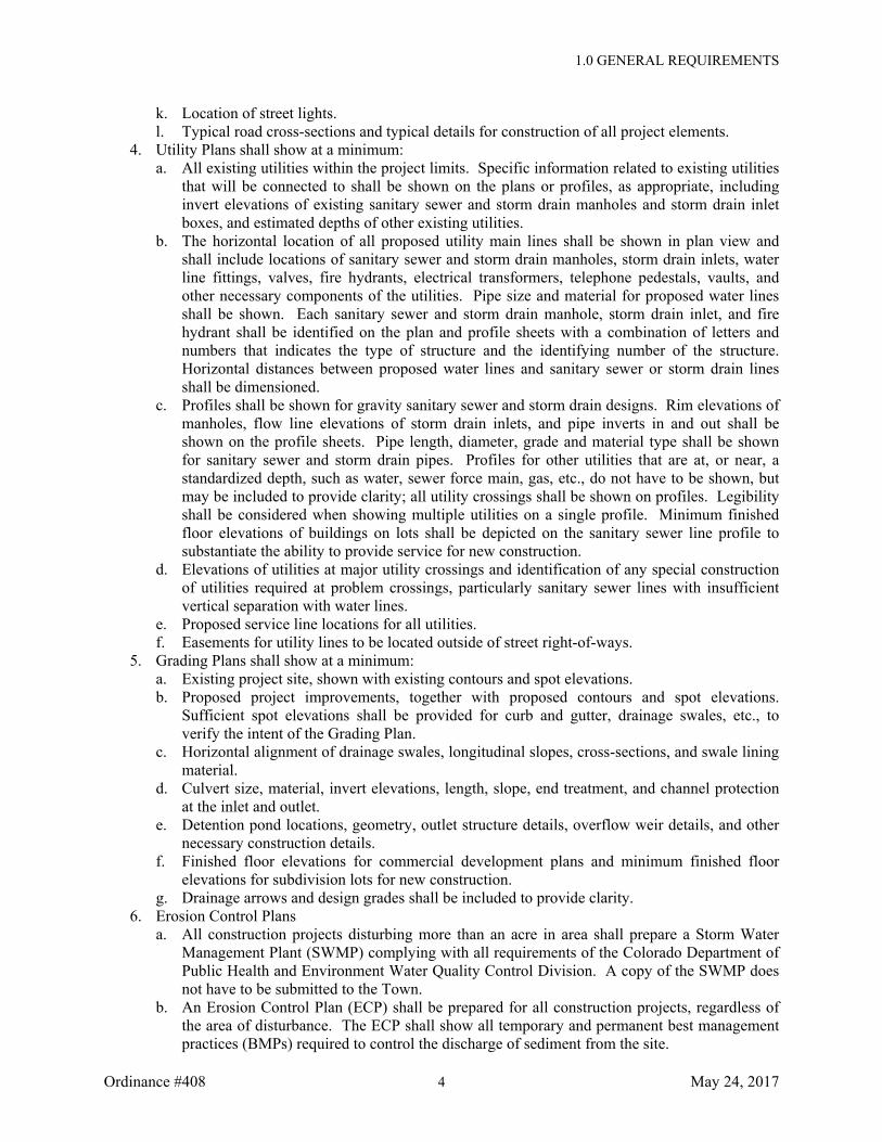
k. Location of street lights. l. Typical road cross-sections and typical details for construction of all project elements.
4. Utility Plans shall show at a minimum: a. All existing utilities within the project limits. Specific information related to existing utilities
that will be connected to shall be shown on the plans or profiles, as appropriate, including invert elevations of existing sanitary sewer and storm drain manholes and storm drain inlet boxes, and estimated depths of other existing utilities.
b. The horizontal location of all proposed utility main lines shall be shown in plan view and shall include locations of sanitary sewer and storm drain manholes, storm drain inlets, water line fittings, valves, fire hydrants, electrical transformers, telephone pedestals, vaults, and other necessary components of the utilities. Pipe size and material for proposed water lines shall be shown. Each sanitary sewer and storm drain manhole, storm drain inlet, and fire hydrant shall be identified on the plan and profile sheets with a combination of letters and numbers that indicates the type of structure and the identifying number of the structure. Horizontal distances between proposed water lines and sanitary sewer or storm drain lines shall be dimensioned.
c. Profiles shall be shown for gravity sanitary sewer and storm drain designs. Rim elevations of manholes, flow line elevations of storm drain inlets, and pipe inverts in and out shall be shown on the profile sheets. Pipe length, diameter, grade and material type shall be shown for sanitary sewer and storm drain pipes. Profiles for other utilities that are at, or near, a standardized depth, such as water, sewer force main, gas, etc., do not have to be shown, but may be included to provide clarity; all utility crossings shall be shown on profiles. Legibility shall be considered when showing multiple utilities on a single profile. Minimum finished floor elevations of buildings on lots shall be depicted on the sanitary sewer line profile to substantiate the ability to provide service for new construction.
d. Elevations of utilities at major utility crossings and identification of any special construction of utilities required at problem crossings, particularly sanitary sewer lines with insufficient vertical separation with water lines.
e. Proposed service line locations for all utilities. f. Easements for utility lines to be located outside of street right-of-ways.
5. Grading Plans shall show at a minimum: a. Existing project site, shown with existing contours and spot elevations. b. Proposed project improvements, together with proposed contours and spot elevations.
Sufficient spot elevations shall be provided for curb and gutter, drainage swales, etc., to verify the intent of the Grading Plan.
c. Horizontal alignment of drainage swales, longitudinal slopes, cross-sections, and swale lining material.
d. Culvert size, material, invert elevations, length, slope, end treatment, and channel protection at the inlet and outlet.
e. Detention pond locations, geometry, outlet structure details, overflow weir details, and other necessary construction details.
f. Finished floor elevations for commercial development plans and minimum finished floor elevations for subdivision lots for new construction.
g. Drainage arrows and design grades shall be included to provide clarity. 6. Erosion Control Plans
a. All construction projects disturbing more than an acre in area shall prepare a Storm Water Management Plant (SWMP) complying with all requirements of the Colorado Department of Public Health and Environment Water Quality Control Division. A copy of the SWMP does not have to be submitted to the Town.
b. An Erosion Control Plan (ECP) shall be prepared for all construction projects, regardless of the area of disturbance. The ECP shall show all temporary and permanent best management practices (BMPs) required to control the discharge of sediment from the site.
1.0 GENERAL REQUIREMENTS
Ordinance #408 5 May 24, 2017
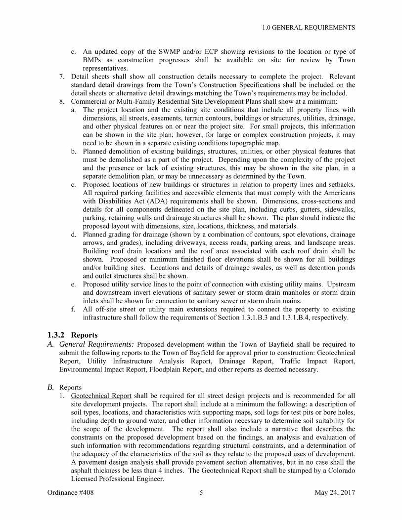
c. An updated copy of the SWMP and/or ECP showing revisions to the location or type of BMPs as construction progresses shall be available on site for review by Town representatives.
7. Detail sheets shall show all construction details necessary to complete the project. Relevant standard detail drawings from the Town’s Construction Specifications shall be included on the detail sheets or alternative detail drawings matching the Town’s requirements may be included.
8. Commercial or Multi-Family Residential Site Development Plans shall show at a minimum: a. The project location and the existing site conditions that include all property lines with
dimensions, all streets, easements, terrain contours, buildings or structures, utilities, drainage, and other physical features on or near the project site. For small projects, this information can be shown in the site plan; however, for large or complex construction projects, it may need to be shown in a separate existing conditions topographic map.
b. Planned demolition of existing buildings, structures, utilities, or other physical features that must be demolished as a part of the project. Depending upon the complexity of the project and the presence or lack of existing structures, this may be shown in the site plan, in a separate demolition plan, or may be unnecessary as determined by the Town.
c. Proposed locations of new buildings or structures in relation to property lines and setbacks. All required parking facilities and accessible elements that must comply with the Americans with Disabilities Act (ADA) requirements shall be shown. Dimensions, cross-sections and details for all components delineated on the site plan, including curbs, gutters, sidewalks, parking, retaining walls and drainage structures shall be shown. The plan should indicate the proposed layout with dimensions, size, locations, thickness, and materials.
d. Planned grading for drainage (shown by a combination of contours, spot elevations, drainage arrows, and grades), including driveways, access roads, parking areas, and landscape areas. Building roof drain locations and the roof area associated with each roof drain shall be shown. Proposed or minimum finished floor elevations shall be shown for all buildings and/or building sites. Locations and details of drainage swales, as well as detention ponds and outlet structures shall be shown.
e. Proposed utility service lines to the point of connection with existing utility mains. Upstream and downstream invert elevations of sanitary sewer or storm drain manholes or storm drain inlets shall be shown for connection to sanitary sewer or storm drain mains.
f. All off-site street or utility main extensions required to connect the property to existing infrastructure shall follow the requirements of Section 1.3.1.B.3 and 1.3.1.B.4, respectively.
1.3.2 Reports A. General Requirements: Proposed development within the Town of Bayfield shall be required to
submit the following reports to the Town of Bayfield for approval prior to construction: Geotechnical Report, Utility Infrastructure Analysis Report, Drainage Report, Traffic Impact Report, Environmental Impact Report, Floodplain Report, and other reports as deemed necessary.
B. Reports
1. Geotechnical Report shall be required for all street design projects and is recommended for all site development projects. The report shall include at a minimum the following: a description of soil types, locations, and characteristics with supporting maps, soil logs for test pits or bore holes, including depth to ground water, and other information necessary to determine soil suitability for the scope of the development. The report shall also include a narrative that describes the constraints on the proposed development based on the findings, an analysis and evaluation of such information with recommendations regarding structural constraints, and a determination of the adequacy of the characteristics of the soil as they relate to the proposed uses of development. A pavement design analysis shall provide pavement section alternatives, but in no case shall the asphalt thickness be less than 4 inches. The Geotechnical Report shall be stamped by a Colorado Licensed Professional Engineer.

1.0 GENERAL REQUIREMENTS
Ordinance #408 6 May 24, 2017
2. Utility Infrastructure Analysis Report shall be required for large projects that have a significant impact on the Town’s existing utility infrastructure. The Town of Bayfield will determine in the planning stages of the project if a Utility Infrastructure Analysis Report will be required. The Report shall estimate sewer or storm drainage flows or water demands and model the system(s) to determine the impacts of the project on the Town’s existing infrastructure. The report shall detail the methods used to determine the flows or demands, list the critical assumptions used in the modeling, describe the modeling method(s) used, include detailed figures that illustrate the impact of the project on the Town’s infrastructure, provide recommendations for improvements to the Town’s infrastructure required to mitigate the impact of the project, and include detailed input and output tables showing the parameters used in the model(s) and the model results. At the Town’s discretion, the impact modelling shall be conducted in accordance with the Town’s existing models. The Utility Infrastructure Analysis Report shall be stamped by a Colorado Licensed Professional Engineer.
3. Drainage Report shall be required for all site development and subdivision projects. The report shall include at a minimum the following: a. Analysis of historic (pre-development) and developed (post-development) conditions,
including drainage patterns and surface cover conditions; soil types and corresponding hydrologic classifications; time of concentration or travel time flow path identified on a map of the site, along with distances, grades, and surface cover used in the calculation segments; identification of any off-site drainage that impacts the site; and quantification of the peak flows associated with the design storm events.
b. Flow calculations showing the normal depth of water for the design storm for all storm drainage conveyances, including street gutters, open channels and storm drain pipes.
c. Inlet capture calculations for on-grade and sump condition inlets, including flow spread, flow depth, and inlet bypass results.
d. Culvert flow calculations, including design flow, culvert geometry, headwater depth, discharge velocity, and discharge depth.
e. Vegetated or riprap swale stability analysis calculations. f. Detention facility design information, including inflow and outflow hydrographs, pond
geometry, outlet structure design, and stage-storage-discharge curves. g. The Drainage Report shall be stamped by a Colorado Licensed Professional Engineer.
4. Traffic Impact Report shall be required for projects generating more than 100 AM or PM peak hour trips as estimated using Institute of Transportation Engineers (ITE) Trip Generation, current edition. The traffic impact report shall follow the guidelines outlined in the Colorado Department of Transportation (CDOT) State Highway Access Code – Section 2.3 (5)(c). The traffic impact report shall also include a description and illustration of mitigation to improve deficiencies identified by the analyses, and may include, but is not limited to, necessary turning lanes, deceleration and acceleration lanes, illumination, or traffic signals. The Traffic Impact Study shall also determine the 18k Equivalent Single Axle Loadings (ESAL) for all facilities for use in the design of the pavement structure in the Geotechnical Report. The Traffic Impact Report shall be prepared and stamped by a Colorado Licensed Professional Engineer.
5. Environmental Impact Report shall be required for projects generating significant impact to the quality of the local environment, as per the Town’s determination. The report shall include at a minimum the following. a. An introduction including a statement of the purpose and need of the proposed action. b. A description of the affected environment. c. A range of possible, feasible alternatives to the proposed action. d. An analysis of the environmental impacts of each of the possible alternative, including, but
not limited to: impacts to threatened or endangered species, air and water quality impacts, impacts to historic and cultural sites, and a cost analysis for each alternative, including costs to mitigate expected impacts.

1.0 GENERAL REQUIREMENTS
Ordinance #408 7 May 24, 2017
e. A “No Action Alternative” identifying the expected environmental impacts in the future if existing conditions were left untouched by the project. Analysis of the “No Action Alternative” shall serve as a baseline upon which to compare the proposed “Action” alternatives.
f. At the Town’s discretion, the report may also include: an analysis of social and economic impacts to local communities and an environmental mitigation plan if substantial environmental impacts are expected.
g. The Environmental Impact Report shall be stamped by a Colorado Licensed Professional Engineer.
6. Floodplain Report shall be required of developments situated within a Federal Emergency Management Agency (FEMA) mapped flood hazard area within the Town of Bayfield to provide assurance that the development does not cause any adverse impact on the stream, or cause flood water surface elevations to increase. The responsible party shall ensure that the procedures and methods of development comply with the Bayfield Land Use Code, Article 10, Section 6-10, Flood Damage Prevention, and the following requirements: a. All provisions and design calculations for flood control shall be established at the hydrologic
point of interest to handle the 100-year frequency storm for the maximum period of intensity over the entire watershed the development lies within. Procedures for preparing floodplain information shall be based on acceptable hydrologic and hydraulic methods approved by the Colorado Water Conservation Board (CWCB).
b. Approximate methods for determination of floodplain information may be used for limited development such as parks, open space, golf courses, agriculture, bridges and culverts that serve a single home and single family structure.
c. Detailed methods for determination of floodplain information are required for significant development that does not fall under one of the categories listed under the limited development. Federal regulations require that developments involving more than 5 acres or more than 50 units submit a detailed study.
d. The Floodplain Report shall be prepared and stamped by a Colorado Licensed Professional Engineer.
7. Copies of other relevant reports, including wetlands delineation, geologic hazards, archaeological or historic surveys, biological surveys, or other reports required by Federal or State agencies shall be submitted to the Town of Bayfield for informational purposes.
1.3.3 Plan Revisions Should circumstances warrant changes to the approved plans or specifications, the proposed revision must be submitted and written approval must be obtained from the Town of Bayfield. No work shall proceed on that portion of the project being revised until said revisions are submitted, approved, and distributed. Minor deviations from the plans or specifications may be by written permission from the Town of Bayfield.
1.3.4 Record Drawings A. It shall be the responsibility of the developer to provide the Town of Bayfield with a set of
Record Drawings at the completion of the project verifying all elevations, all utility locations (including service line locations), including any changes from the approved construction plans that have occurred during construction.
B. As-built horizontal locations and elevations of utilities shall be established by a field survey after
construction is complete for accessible utility structures (sewer and storm drain manholes, storm drain inlets, culverts, valve boxes, curb stops, fire hydrants, and other similar structures) and during construction for utility structures or features that are not accessible after backfilling (service line locations at the tap and curb, water line and force main bends and deflections following street or easement alignments, unusual water line or force main depths at crossings

1.0 GENERAL REQUIREMENTS
Ordinance #408 8 May 24, 2017
with other utilities or through significant cut or fill sections, utilities provided by other utility providers, and conduit or casing pipe installed for future use). The field survey shall be performed by a surveyor selected by the Town and tied to NAD 83 and NAVD 88. The developer or contractor shall be responsible for coordinating the site visits by the surveyor. In the case that something is buried prior to the survey, the contractor will be responsible to expose for survey at own expense. The developer shall be responsible for the costs of the “as-built” survey, as invoiced by the Town, and development of the Record Drawings from the survey data.
C. Three 24”x36” paper copies of the Record Drawings, stamped by a Colorado Licensed Professional Engineer or Architect, shall be submitted to the Town prior to final acceptance of public improvements. In addition, electronic drawings (CAD or GIS) of public utilities and streets, at a minimum, shall be submitted to the Town prior to final acceptance of the improvements. Electronic Drawings provided to the Town shall be survey grade. The Electronic Drawing information shall specifically include water line locations, all tees, mechanical joints, valves, hydrants, curb stops, meter pits and horizontal and vertical alignment information at every 100 feet. Electronic Drawing information for sanitary sewer systems shall include at a minimum, locations of manholes, service taps and horizontal alignment data for every 100 feet. Electronic Drawing information for storm sewer systems shall include at a minimum location of manholes, depths and alignment data in 100 foot intervals. Failure to submit drawings shall result in no Certificate of Occupancy or final approval by the Town of Bayfield.
D. A fee will be charged for any proposed development to update the water, sanitary sewer, road, and storm sewer computer models or any infrastructure GIS, survey, or CAD mapping updates. The fee will be determined based on the complexity of the development.

2.0 STREETS
Ordinance #408 9 May 24, 2017
2.0 STREETS
2.1 GENERAL 2.1.1 Description A. The street system shall be designed to provide safe and convenient access for traffic and emergency
vehicles to properties within the Town of Bayfield and provide access to connecting County roads and State highways. The street system shall conform to the Town of Bayfield Land Use Code (LUC) and the Bayfield Comprehensive Transportation Plan, as well as all other relevant Town planning documents. Street and intersection design shall conform to the design standards of the American Association of State Highway and Transportation Officials’ (AASHTO) A Policy on Geometric Design of Highways and Streets, latest edition, for the appropriate street classification. Streets connecting to County roads or State Highways shall meet all requirements of La Plata County or the Colorado Department of Transportation, respectively, at the points of connection. All street facilities shall be designed by a Colorado Licensed Professional Engineer and shall comply with these design criteria, specifications, and standard drawings. All street system construction plans shall be approved by the Town of Bayfield prior to beginning of any construction.
B. New street layout shall consider the need for the extension of existing streets, existing and desired
circulation patterns, the natural topography, platted streets on adjacent properties, and existing and anticipated land uses. Residential streets shall be arranged so as to discourage through traffic.
C. Street classifications include arterial, collector, and local streets, as defined in the LUC, and as shown
on the Bayfield Comprehensive Transportation Plan. Street and intersection layout criteria shall meet the requirements of these standards and the LUC.
2.2 DESIGN CRITERIA 2.2.1 Street Classification A. Arterial Streets: Arterial streets are intended to carry the largest volume of traffic through town and
connect to adjoining State highways and County roads. Arterial streets shall be located a maximum of one mile apart and as shown on the Bayfield Comprehensive Transportation Plan.
B. Collector Streets: Collector streets provide connections between local streets and arterial streets. A
collector street shall be required when serving more than 200 dwelling units within a residential subdivision and be centrally located to the properties served.
C. Local Streets: Local streets provide frontage for access to lots and carries traffic that has origin or
destination at lots adjacent to the streets. Local streets are designed to carry the least amount of traffic at the lowest speed. Residential units shall front on this class of street to the maximum extent possible. Design of local streets shall discourage through traffic.
D. Alley: A service road located at the back of lots that provides a secondary means of access. 2.2.2 Street Design Criteria A. Right of Way: Street rights-of-way shall be sufficient to accommodate vehicular traffic, bicycles,
pedestrians, public utilities, storm drainage facilities, slopes, and other special considerations such as medians, or traffic calming devices and acceleration/deceleration channelization. Street rights of way shall meet the width requirements for the relevant street classification, as shown in Table 2.1. Greater widths may be required by the Town to accommodate these features or when the need for such additional width is supported by a traffic study.

2.0 STREETS
Ordinance #408 10 May 24, 2017
Table 2.1 Street Design Criteria
Street Classification Major
Arterial Arterial Collector Local Cul-de-saca AlleyMinimum Right-of-Way Width (ft) 100 80 60 60 60 (radius) 20Minimum Pavement Width (ft) 44 44 40 32 50 (radius) 20Design Speed (mph) 40 35 30 25 25 15Maximum Grade (%) 5 5 7 10 10 10Minimum Stopping Sight Distance (ft)
326 266 219 176 176 86
Minimum Centerline Horizontal Curve Radius (ft)
600 415 275 165 165 45
Minimum Tangent Between Horizontal Reverse Curves (ft)
200 200 150 100 100 100
Minimum Rate of Vertical Curvature, K, for Crest Curves
44 29 19 12 12 7
Minimum Rate of Vertical Curvature, K, for Sag Curves
64 49 37 26 26 17
Notes: a Applicable only for approved cul-de-sacs.
1. The values in this table are design requirements unless otherwise approved by the Town. 2. Minimum stopping sight distance based on AASHTO equations, 2.5 second reaction time, deceleration rate of 11.2
ft/s2, design speed, wet-pavement conditions, and maximum downgrade conditions. 3. Minimum centerline horizontal curve radius based on AASHTO equations for low speed urban streets; side friction
factors of 0.330 for 15 mph, 0.252 for 25 mph, 0.221 for 30 mph, 0.197 for 35 mph; 0.178 for 40 mph; and no superelevation.
4. Minimum rates of vertical curvature, K (equal to the length of the curve, L, divided by the algebraic difference in intersecting grades, A) based on AASHTO equations for minimum stopping sight distance on crest curves and considering illumination of the minimum stopping sight distance by headlights on sag curves.
B. Pavement Width: Streets shall meet the pavement width requirements , unless otherwise approved by
the Town. Street widths are measured to the back of curb where curb and gutter is planned or to the edge of the shoulder, where curb and gutter is absent.
C. On-Street Parking: On-street parking shall be parallel only for all new development, unless otherwise
approved by the Town, and shall be a minimum of 8 feet in width. Diagonal parking may be allowed in commercial areas, if approved by the Town.
2.2.3 Street Design A. General: Street design shall consider existing topography, horizontal and vertical alignment, sight
distance, property access, connection to existing streets, and future extension potential to produce streets that are safe, functional, aesthetic, and economical to maintain. Streets shall conform to the design criteria shown in Table 2.1. Designs shall exceed minimum design requirements (stopping sight distance, horizontal curve radius, tangent lengths, etc.) to the extent possible.
B. Street Grades: Street grades shall take into consideration the natural topography, potential future
street connections, and the relationship to adjoining properties. Maximum street grades for the various street classifications are shown in Table 2.1. The grades of streets steeper than 5% shall transition to a maximum 5% grade (3% preferred) for a minimum of 50 feet prior to the intersection. The minimum street grade allowed is 0.5%, with a preferred minimum grade of 1.0%. Minimum and maximum street grades are to be avoided whenever possible; however, steeper grades over short distances necessary as a result of the natural topography may be allowed upon approval of the Town of Bayfield.

2.0 STREETS
Ordinance #408 11 May 24, 2017
C. Street Cross Section: The standard street cross section shall establish positive surface drainage by incorporating a crowned section along the street centerline with 2% cross slope downward toward both edges. Unidirectional cross slopes and maximum cross slopes of up to 4% may be allowed upon approval of the Town of Bayfield.
D. Stopping Sight Distance: Streets shall be designed so that all elements meet the applicable AASHTO
stopping sight distance requirements based on the design speed and grades of the street. Table 2.1 shows minimum stopping sight distances for maximum downgrade conditions. Stopping sight distances shall be determined at 3.5 feet, the estimated height of a driver’s eye, for an object at a height of 2.0 feet, the equivalent height of a passenger car taillight.
E. Horizontal alignment: All horizontal alignments shall be designed to exceed the requirements shown
in Table 2.1 for the relevant street classification. All changes in the horizontal alignment that exceed one (1) degree shall incorporate a simple horizontal curve consistent with the design speed of the street. Curves in the same direction with a short tangent between the curves (“flat-backed curves”) shall be avoided.
F. Vertical alignment: Street grades shall take into consideration the natural topography, potential future
street connections, and the relationship to adjoining properties. Streets shall be depressed relative to the surrounding terrain to allow drainage from adjacent properties to the street, when possible. Maximum street grades for the various street classifications are shown in Table 2.1. All changes in roadway grade having an algebraic difference of 1% between the two grades shall be connected by a symmetric parabolic curve of not less than 100 feet length or three times the design speed, whichever is greater. The minimum length of vertical curves, L (ft), shall also be determined as the product of the minimum rate of curvature, K, shown in Table 3.1 for the relevant street classification and crest or sag condition, multiplied by the algebraic difference in street grades in percent, A, as follows: L = KA. Crest and sag vertical curves with high and low points, respectively, must also achieve a minimum of 0.5% grade within 50 feet of the crest by achieving a maximum rate of curvature, K, of 100. All vertical alignments shall be designed to exceed the AASHTO sight distance requirements for the street classifications shown in Table 2.1.
G. Clearance to obstructions: A minimum horizontal clearance of 1.5 feet shall be maintained between
the face of the curb and roadside obstructions, such as fire hydrants, traffic or other signs, utility poles, and lighting poles. Overhead obstructions, including traffic signal supports, signs, and utility lines, shall maintain a minimum vertical clearance of 18 feet across the entire roadway surface.
H. All traffic control devices, including signing and striping, shall conform to the requirements of the
latest Federal Highway Administration Manual on Uniform Traffic Control Devices (MUTCD).
I. All sign posts, light standards, and other roadside appurtenances shall meet the breakaway criteria as detailed in the AASHTO Roadside Design Guide or as approved by the Town of Bayfield.
J. Cul-de-sacs are not allowed unless specifically approved by the Town. When allowed by the town,
maximum cul-de-sac lengths shall be 500 feet and shall feature a circular turn-around with radius as shown in Table 2.1. Temporary dead end streets that are to be extended in the future to a street connection may be approved if the turn-around requirements of cul-de-sacs are provided. Dead end alleys shall not be permitted.
K. Medians, traffic calming devices, turn lanes, superelevation, and traffic signals will be considered on
a case-by-case basis.

2.0 STREETS
Ordinance #408 12 May 24, 2017
2.2.4 Intersection Design A. Streets shall be laid out so that they intersect at right angles to the extent possible, but in no case shall
the angle of intersection vary more than 20 degrees from a right angle. Streets that approach intersections at an angle more than 20 degrees from a right angle shall feature a right angle intersection with a minimum of 50 feet of roadway before transitioning to the street approach alignment.
B. Intersections that include collector or arterial streets shall be designed to allow for future traffic signalization.
C. No intersection of public or private streets shall be on a curve of centerline radius less than 500 feet. D. Streets entering opposite sides of a street shall either be directly across from each other or be offset by
a distance at least equal to the stopping sight distance of the facility measured from centerline to centerline of the approaches.
E. Streets shall not enter onto the same side of a street with less than a distance equal to the stopping
sight distance for the major street from centerline to centerline. F. Intersection curb radii shall be a minimum of 20 feet for all streets, except that curb radii in
commercial and industrial areas and for arterial streets shall be 30 feet. G. Intersections shall meet AASHTO guidelines for approach and departure sight triangle distances
determined for a driver’s eye at 3.5 feet above the roadway surface and the object to be seen at 3.5 feet above the surface of the intersecting road. Sight triangle distances shall consider the means of traffic control, type of traffic (primarily passenger vehicles or substantial truck traffic), street widths, and street grades. Traffic control devices and utility/light poles are allowed within the design sight triangle, but no other objects that obstruct the design line of sight are permitted. Table 2.2 below provides sight triangle distances meeting AASHTO guidelines for intersections featuring primarily passenger vehicle traffic and grades of 3% or less for the relevant street design speeds and means of intersection control. Sight triangle distances for intersections featuring multiple lanes, medians, parking lanes, bicycle lanes, or other variations from two-lane street widths, streets with a substantial amount of truck traffic, or streets with grades steeper than 3% shall be adjusted, as required, using AASHTO guidelines.
2.2.5 Secondary Access Requirements A. Subdivisions with 5 to 20 units or 5 to 20 single family lots shall have one primary access meeting the
minimum requirements for a local street. In addition, such subdivisions shall have an emergency access a minimum of 12 feet in width and approved by the Upper Pine River Fire Protection District (UPRFPD).
B. Residential subdivisions with more than 20 lots shall have a minimum of two primary access streets.
The access streets shall meet the requirements for a local street, at a minimum. One or both of the access streets may be required to meet the requirements of a collector street.
C. Commercial/Industrial developments with greater than 25,000 square feet of usable floor area shall have secondary access unless it is determined to be unnecessary by the Town.
D. In addition to the above requirements, a secondary access shall be required for any development in
which a traffic study (using cumulative traffic impact) indicates that additional access is needed or when the UPRFPD, Town Engineer, and Planning Commission determine that a secondary access is necessary for safety purposes.

2.0 STREETS
Ordinance #408 13 May 24, 2017
Table 2.2 Intersection Sight Triangle Design Criteria
Intersection Control and Movement
Design Speed (mph)35 30 25 15Sight Triangle Length (ft)
Case A: Intersections with no control1 165 140 115 70Case B: Intersections with minor street stop control
Case B1: Left turns from the minor street2 390 335 280 170Case B2: Right turns to, and Case B3: Crossings of, the major street from a minor street approach2 335 290 240 145
Case C: Intersections with minor street yield control Case C1: Crossing maneuver from the minor street (minor street leg length/major street leg length)3
195/ 345
160/ 300
130/ 250
75/ 150
Case C2: Left or right turn from the minor street4 415 355 295 180
Case D: Intersections with traffic control signal
First vehicle on each approach shall be visible to the first vehicle on all other approaches. Left-turning vehicles shall have sufficient sight distance to select gaps in oncoming traffic and complete left turns. Case B2 departure sight distances to left shall be provided for right turns on red light.
Case E: Intersections with all-way stop control First vehicle on each approach shall be visible to the first vehicle on all other approaches
Case F: Left turn from the major street 285 245 205 1251 Sight triangle distances shall be determined for both legs using the respective design speeds. 2 The vertex of the minor street sight triangle leg shall be 18 feet from the edge of the major street drive lane. Minor street sight
triangle leg distances shall be 18 feet plus ½ the driving lane width for left-approaching vehicles and 1½ the driving lane width for right-approaching vehicles.
3 Sight triangle distances shall be determined for both legs using the respective design speeds. 4 The vertex of the minor street sight triangle leg shall be 82 feet.
2.2.6 Pavement Design A. The structural section of the street shall be designed to meet the projected traffic volumes and vehicle
types. However, no section less than the following will be approved: 4” Hot Mix Asphalt 4” Aggregate Base Course, CDOT Class 6 8” Aggregate Base Course, CDOT Class 2
2.2.7 Curb & Gutter A. Concrete curb and gutter are required on all streets and medians, unless otherwise approved.
Mountable curbs are recommended for residential developments with undefined driveway locations. All curbs shall have a height of 6 inches.
B. Gutter cross slopes shall be 1” per foot when draining toward the curb and ½” per foot when draining
away from the curb. Additional gutter depression may be used at inlets to enhance storm drainage capacity when approved by the Town.
C. Concrete valley gutters shall be provided at intersections to direct gutter flow across the intersection.
The concrete fillet area at the curb returns shall be a monolithic pour with the curb.

2.0 STREETS
Ordinance #408 14 May 24, 2017
D. Fibermesh Reinforcement: Fibermesh reinforcement fibers shall be 2-inches to 3-inches collated polypropylene fibers. Fibers shall be in strict accordance with the manufacturer recommendations and within the time as specified in ASTM C94, Type III 4.13 and applicable building codes.
a. Synthetic Fiber Reinforcement: Fibermesh 150 b. Material: 100 percent virgin homopolymer polypropylene multifilament fibers,
containing no reprocessed olefin materials. c. Conformance: ASTM C 1116, Type III.
2.2.8 Sidewalks A. Sidewalks shall be provided on both sides of all public streets and shall be a minimum of 5 feet in
width for residential areas; sidewalks in commercial districts shall be a minimum of 8 feet in width. Sidewalks shall typically be located within street rights-of-way and parallel to the street, either attached to or detached from the curb, unless otherwise approved by the Town. Alternative alignments that preserve topographical or natural features or provide visual interest may be approved by the Town if they provide safe and convenient pedestrian circulation.
B. All sidewalks shall comply with ADA requirements, including maximum longitudinal and cross slopes and design of sidewalk ramps. A minimum clear passage width of 36 inches shall be provided where sidewalk obstructions, such as fire hydrants, traffic signs, or other obstructions occur. Sidewalk crossings of driveways shall comply with ADA requirements.
C. Sidewalk (curb) ramps shall be provided at intersection corners on public streets and at intermediate
locations where the distance between intersections warrants additional access. Where pedestrian and/or vehicular volumes are moderate to high, locating ramps at the ends of the curb radius is preferred over a single ramp at the middle of the curb radius. All ramps shall meet ADA requirements and feature ADA-compliant detectable warning panels.
D. Pedestrian walkways, consisting of minimum 5-foot wide sidewalks, centered in a 10-foot wide easement, may be required by the Town through the center of a block more than 600 feet long to provide circulation or access to schools, playgrounds, shopping, or other community facilities.
E. Fibermesh Reinforcement: Fibermesh reinforcement fibers shall be 2-inches to 3-inches collated
polypropylene fibers. Fibers shall be in strict accordance with the manufacturer recommendations and within the time as specified in ASTM C94, Type III 4.13 and applicable building codes.
a. Synthetic Fiber Reinforcement: Fibermesh 150 b. Material: 100 percent virgin homopolymer polypropylene multifilament fibers,
containing no reprocessed olefin materials. c. Conformance: ASTM C 1116, Type III.
2.2.9 Pedestrian and Bike Paths A. Stand-alone pedestrian and bike paths shall be constructed of asphalt or concrete pavement, as
required by the Town, 10 feet in width along alignments designated by the Town. Paths shall meet ADA requirements, including maximum longitudinal grades and cross-slopes. ADA-compliant detectable warning panels shall be located at all street crossings. Paths not located within street ROW shall be located within a 20-ft wide easement or width necessary to accommodate the path topography, as required by the Town.
2.2.10 Driveways A. Driveways shall be perpendicular to streets unless otherwise approved. Driveway design standards
are shown in Table 2.3 below.

2.0 STREETS
Ordinance #408 15 May 24, 2017
Table 2.3 Driveway Design Criteria Criterion Commercial Residential
Minimum Throat Width (ft) 24 10Maximum Throat Width (ft) 40 20Maximum Grade (%) 8 12Minimum Radius (ft) 20 N/AMaximum Radius(ft) 40 N/A
Notes: 1. The values in this table are design requirements unless otherwise approved
by the Town of Bayfield. 2. Widths shown are based on two-way driveways. One-way driveways for
commercial facilities will be approved on a case-by-case basis. B. A maximum of one driveway shall be allowed per residential lot. A maximum of two driveways are
allowed per commercial lot frontage, provided a minimum of 25 feet between the driveway inside curb return tangent points or driveway “wings” can be achieved. Required distance between driveways shall consider road classification, sight distance, distance from adjacent driveways, street intersections, and other factors as determined by the Town.
C. No curb cut will be allowed on a curve section of road whose inside curve radius is less than 150 feet. D. Residential driveways shall extend a minimum of 20 feet between the back edge of the sidewalk and
the residence to allow for off-street parking. Sidewalk crossings of driveways shall comply with ADA requirements.
2.2.11 Bicycle Lanes A. Bicycle lanes, where required on arterial and collector streets, shall be a minimum of 3 feet in width
where on-street parallel parking is provided, and a minimum of 4 feet in width where on-street parking is not provided or diagonal on-street parking is provided.
2.2.12 Street Lighting A. Reserved.

3.0 DOMESTIC WATER SYSTEM
Ordinance #408 16 May 24, 2017
3.0 DOMESTIC WATER SYSTEM
3.1 GENERAL 3.1.1 Description A. All water distribution facilities shall be located within the public right-of-way, unless otherwise
approved by the Town; a minimum 30-foot wide utility easement, centered on the water line, shall be provided for water distribution mains located outside of the public right-of-way. Easements for other water system facilities shall be considered on a case-by-case basis.
B. All water distribution facilities shall comply with these design criteria, specifications, and standard
drawings. In addition, all minimum standards of relevant Federal and State agencies shall be followed in the planning and construction of water pumping, distribution, and transmission facilities. All water mains and appurtenances shall be designed by a Colorado Licensed Professional Engineer. All water system construction plans shall be approved by the Town prior to beginning of any construction.
3.2 DESIGN CRITERIA 3.2.1 Distribution System Layout A. All water mains shall be looped to the extent possible. Dead end water mains shall not be allowed
unless approved by the Town. Fire hydrants shall be installed at the ends of approved dead end mains.
B. Water mains shall be located 12 feet north or east of street centerlines, where possible. Water mains
located within streets shall follow the street alignments as closely as possible through longitudinal bending of the pipe, or use of fittings. Limits of longitudinal bending shall be within pipe manufacturers’ recommendations. Horizontal separation from other utilities shall be as specified in Section 3.2.9.
C. All water mains shall be extended to the furthest property line of any lot or development whenever
future development is possible. 3.2.2 Water Main Size A. The minimum water main pipe size shall be 8 inches in diameter. The pipe diameter may be required
to be increased if the Town of Bayfield determines it to be necessary to meet fire flow requirements, where the potential exists for future development, or to meet present demand. If the Town requires a developer to increase the size of water mains in a development or subdivision to meet future expansion needs, the Town may enter into a cost-sharing agreement with the developer.
B. Water mains shall be sized to deliver fire flow requirements, as determined by the UPRFPD. The
UPRFPD shall be consulted when designing the location and size of water mains and fire hydrants. 3.2.3 Depth A. All water mains shall have a minimum cover of 48 inches from the top of pipe to the finished surface
grade. Water mains shall parallel the surface topography as closely as reasonable through the use of longitudinal bending of the pipe or deflection of pipe joints, or through the use of fittings where abrupt depth changes are necessary. Limits of longitudinal bending and joint deflection shall be within pipe manufacturers’ recommendations. Excessive depths shall be avoided. Vertical separation from other utilities shall be as specified in Section 3.2.9.

3.0 DOMESTIC WATER SYSTEM
Ordinance #408 17 May 24, 2017
3.2.4 Valves A. Shut-Off Valves: Shut-off valves shall be located with a maximum spacing of 400 feet on all
distribution mains and 1,000 feet on all transmission mains, or as determined by the Town. Valves shall be located on all branches of crosses and tees, except at fire hydrant tees, unless otherwise approved by the Town of Bayfield. In addition, valves shall be located such that no single shut down will result in more than one block of continuous line off at one time and in no case shall more than one fire hydrant along a section of main be removed from service. The Town of Bayfield may require valves at more frequent spacing if deemed necessary. Shut-off valves less than 16 inches in size shall be gate valves; shut-off valves 16 inches or larger in size shall be butterfly valves. Shut-off valves shall be in accordance with Standard Detail Nos. W-02 and W-03.
B. Air Release Valves: As directed by the Town of Bayfield, air/vacuum release valves or combination
valves may be required at high points in system transmission mains to evacuate air from the pipe when filled, to allow discharge of air accumulated under operating pressure, or permit air to enter the pipe when it is being emptied or subjected to a vacuum. Distribution mains generally allow discharge of air through service connections along the length of the main and at high points. If service connections are limited, the Town of Bayfield may require the installation of a fire hydrant or blow-off at high points or dead ends to allow the release of accumulated air.
3.2.5 Fire Hydrants A. All aspects of fire hydrants, including spacing, location, orientation, and protection, shall be
coordinated with the UPRFPD and shall be in compliance with the Town’s current Fire Code, with the most restrictive requirements applying. At a minimum, one hydrant shall be located at the intersection of all streets. All fire hydrants shall be installed as shown on Standard Detail No. W-01, except hydrants located on permanent dead ends shall be installed without the tee. Water lines to fire hydrants shall have a minimum of 4 feet of cover. A three foot clear space shall be maintained around the circumference of all fire hydrants. Hydrants shall be protected if subject to mechanical/vehicular damage. The means of protection shall be arranged in a manner that will not interfere with the connection to, or operation of, hydrants.
3.2.6 Pipe Joint Restraint A. Restraint for water main fittings, including bends, tees, dead ends, and crosses with dead end
branches, shall consist of both mechanical joint restraints, i.e., EBAA Iron MEGALUG® joint restraints, or equal, and thrust blocks. Thrust block sizing and mechanically restrained pipe lengths shall consider the bearing pressure of the soil, pipe size, type of fitting, and static water pressure (See Standard Detail No. W-06). Concrete used for thrust blocking shall be Class B concrete.
3.2.7 Water Services A. Services: Single family and multi-family residential lots shall be served by an individual service line
and meter (one per unit); in no case shall a single service line and meter serve more than one residential lot, unless approved by the Town. Services and meters for commercial properties shall be decided by the Town on a case-by-case basis.
B. Service Lines: Single family residential service lines shall be ¾-inch, minimum; multi-family and
commercial service line sizes shall be determined based upon the number of fixture units and shall be 1-inch, minimum, unless otherwise approved by the Town. Line locations in new developments with curb and gutter shall be marked with a 2-inch “W” stamped in the top of the curb while the concrete is still wet. Tracer wire shall be extended from the water main to the meter pit, as described in

3.0 DOMESTIC WATER SYSTEM
Ordinance #408 18 May 24, 2017
Section 3.2.8. All private irrigation system connections shall be to the service line on the customer side of the meter and include necessary backflow prevention devices.
C. Meters: All connections to the Town water distribution system shall be metered with an
appropriately sized meter in accordance with AWWA recommendations. The minimum residential meter shall be ¾ inch and the minimum commercial meter shall be 1 inch. Where sidewalks are detached from the curb, the meter pit shall be installed 2 feet behind the curb. Where sidewalks are attached to the curb, the meter pit shall be installed 2 feet behind the sidewalk, except for commercial property where the sidewalk extends to the building, in which case the meter shall be installed 2 feet behind the curb. All meters shall be located in the Town of Bayfield ROW in an accessible location for reading and servicing.
D. Backflow Prevention Devices: All backflow prevention devices shall be Reduced Pressure
Zone (RPZ) assemblies unless otherwise approved by the Town and shall be installed immediately after the meter unless otherwise approved by the Town.
3.2.8 Underground Warning Tape and Tracer Wire A. Underground warning tape shall be installed 12 inches above the top of pipe. (See Standard Detail
No. T-01). Tracer wire for PVC and HDPE water mains shall be blue, minimum 10-gauge solid copper, for direct bury, taped to the top of the pipe. Tracer wire shall be extended upward into valve boxes, to fire hydrants, and along service lines and upward into meter pits (See Standard Detail Nos. W-01 through W-05).
3.2.9 Separation of Water and Other Utilities A. Parallel Installations: Water mains shall be horizontally separated from sanitary sewer or storm drain
mains and manholes, force mains, and storm drain inlets by a minimum of 10 feet between the outside walls of the pipes or structures. When design conditions prevent achieving this separation, the sanitary sewer or storm drain main shall be constructed of C900 PVC or other Town-approved AWWA pressure-rated pipe with mechanical or slip-on joints.
B. Water Main Crossings: Where water mains cross sanitary sewer or storm drain mains or force mains,
there shall be a minimum of 18 inches of vertical separation between the outsides of the pipes. When design conditions prevent achieving this separation, including when the sanitary sewer or storm drain crosses above the water main, the sanitary sewer or storm drain main shall be constructed of a full length of C900 PVC or other Town-approved AWWA pressure-rated pipe, centered on the crossing, with mechanical or slip-on joints and pressure-rated couplings to transition to the sanitary sewer or storm drain pipe material, and EBAA Iron MEGALUG® joint restraints, or equal, on all joints. If the full pipe length is less than 18 feet long, additional pipe lengths shall be installed until reaching 9 feet on both sides of the water main.
C. Service Line Separation: Water service lines shall be separated from sanitary sewer service lines by 5
feet of undisturbed or compacted earth, or in accordance with the Town’s current Plumbing Code. D. Other Utilities: Other utility providers shall be consulted for separation requirements for the
providers’ utilities. 3.2.10 Access to Facilities A. Water distribution facilities located outside of paved areas that require access for maintenance and
operation, such as valves, fire hydrants, etc., shall be provided with a 14-foot wide all-weather access

3.0 DOMESTIC WATER SYSTEM
Ordinance #408 19 May 24, 2017
drive, consisting of a minimum of 6 inches of CDOT Class 6, compacted to 95% of maximum density. The Town may require installation of a geogrid beneath the base course material in areas with poor soil conditions.

4.0 SANITARY SEWER SYSTEM
Ordinance #408 20 May 24, 2017
4.0 SANITARY SEWER SYSTEM
4.1 GENERAL 4.1.1 Description A. All sanitary sewer facilities, including gravity collection mains, manholes, lift stations, force mains,
and other related appurtenances, shall be located within the public right-of-way, unless otherwise approved by the Town; a 30-foot wide utility easement, centered on the sewer line, shall be provided for sewer mains located outside of the public right-of-way unless the depth of the sewer line or the presence of other utilities within the easement justifies a wider easement in the opinion of the Town. Easements for other sewer system facilities shall be considered on a case-by-case basis.
B. All sanitary sewer collection facilities shall comply with these design criteria, specifications, and
standard drawings. In addition, all minimum standards of relevant Federal and State agencies shall be followed in the planning and construction of wastewater collection and pumping facilities. All sanitary sewer collection facilities shall be designed by a Colorado Licensed Professional Engineer. All sanitary sewer collection construction plans shall be approved by the Town prior to beginning of any construction.
C. Sanitary sewer flow calculations shall use a standard estimate of 250 gallons per day per equivalent
residential tap (ERT), as determined by the Town of Bayfield and the estimated peak hour flow rate at the point of analysis. Peak hour flow rates shall be developed from average daily flow rates using the following equation:
10004
100018
P
PPF
,
where PF = peaking factor (ratio of peak hour flow to average daily flow), and P = contributing population equivalent. The contributing population equivalent shall be determined from the number of ERTs using the average household size for the Town of Bayfield from the most recent census data.
D. Direction of rainwater runoff and ground water from all sources, including roof drains, storm drains,
foundation drains, sump pumps, and other sources into the sanitary sewer is strictly prohibited.
4.2 DESIGN CRITERIA 4.2.1 Collection System Layout A. Collection: Sanitary sewer mains shall function by gravity flow whenever possible. The use of lift
stations and force mains must be approved by the Town. Alternative collection systems, including pressure, vacuum, and effluent sewers, will be considered on a case-by-case basis.
B. Pipe Alignment: Gravity collection mains and force mains shall be located along street centerlines, to
the extent possible. Gravity mains shall feature straight alignment, both horizontally and vertically, between manholes; curved sewers will be considered on a case-by-case basis. Increased frequency of manholes on gravity mains shall be used to maintain close alignment with the street centerline and minimize crossings of other utilities. All gravity sewer mains shall be extended to the furthest property line of any lot or development whenever extension of the collection line would serve future development. Force mains shall use longitudinal bending of the pipe, deflection of pipe joints, or fittings to follow the centerline alignment. Limits of longitudinal bending and joint deflection shall

4.0 SANITARY SEWER SYSTEM
Ordinance #408 21 May 24, 2017
be within pipe manufacturers’ recommendations. Horizontal separation from other utilities shall be as specified in Section 4.2.12.
C. Manholes: Manholes shall be installed on gravity collection mains at distances not exceeding 400
feet; at all changes in size, grade, and direction; at all intersections of collection mains; and at the upper end of all mains or as determined by the Town. Manholes at the ends of gravity mains that may be extended in the future shall have a pipe stubbed in the direction of the future extension and capped. Manholes shall not be located in gutter flow lines of streets to prevent storm water inflow. Manholes that must be located in unpaved areas with the potential for storm water inflow through the cover may be approved if they are protected from inflow by either elevating the rim above the anticipated water level or through the specification of water-tight covers.
D. Force Main Connections: Force main connections to gravity sewer mains shall be at manholes. The
connection shall be designed so that the wastewater does not enter the manhole under pressure or at high velocity. This shall be accomplished immediately upstream of the manhole by transitioning from the force main pipe to a larger diameter pipe of at least 20 feet in length installed at minimum grade between the pipe transition and the manhole connection.
4.2.2 Sewer Main Size A. Gravity Mains:
1. Gravity mains that are 15 inches in diameter or smaller shall be designed to flow not more than 50% full when conveying the peak hour flow; gravity mains that are greater than 15 inches in diameter shall be designed to flow not more than 75% full when conveying the peak hour flow. Flow depths shall be determined using the ERT flow estimate and peaking factor as specified in Section 4.1.1.C, Manning’s equation, and a Manning’s “n” of 0.010 for PVC pipe.
2. The minimum gravity sewer main pipe size shall be 8 inches in diameter. The pipe diameter may be required to be increased where the potential exists for future development. If the Town requires a developer to increase the size of sewer mains in a development or subdivision to meet future expansion needs, the Town may enter into a cost-sharing agreement with the developer. Six-inch pipe may be allowed for gravity lines serving a limited number of residents upon approval of the Town of Bayfield.
3. The downstream pipe diameter shall always be equal to or larger than the largest upstream pipe size even if a greater downstream slope would allow a smaller pipe size based on flow capacity.
B. Force Mains:
1. Force main pipe sizes shall be determined considering the anticipated flow, the design pump curve, pipe friction loss, and maintenance of a minimum of 2 feet per second velocity. Design flows shall be determined using the ERT flow estimate and peaking factor as specified in Section 4.1.1.C. Excess residence time (greater than 5 hours) shall be avoided to the extent possible. Parallel force mains shall be considered for lift stations with a significant capacity for future growth.
2. The minimum force main pipe size shall be 4 inches in diameter. 4.2.3 Sewer Main Depth A. Gravity Mains: The depth of gravity sewer mains shall consider the elevations of the adjacent
properties to be served, including the need to service basements, and shall provide sufficient drop from the properties to the sewer main without requiring an excess amount of fill on the properties. The depth of gravity sewer mains shall also consider other utility depths at crossings. In particular, increased depth of the sewer line shall be considered so that the sewer main crosses underneath water lines at sewer-water crossings whenever possible. Gravity sewer lines shall have a minimum cover of 3 feet from the top of pipe to the finished grade surface along the entire length of the line. Drop

4.0 SANITARY SEWER SYSTEM
Ordinance #408 22 May 24, 2017
manholes shall be used when a sewer line enters a manhole more than 2 feet above the lowest invert of the manhole. Vertical separation from other utilities shall be as specified in Section 4.2.12.
B. Force Mains: All force mains shall have a minimum cover of 48 inches from the top of pipe to the
finished surface grade. Force mains shall parallel the surface topography as closely as reasonable through the use of longitudinal bending of the pipe or deflection of pipe joints, or through the use of fittings where abrupt depth changes are necessary. Limits of longitudinal bending and joint deflection shall be within pipe manufacturers’ recommendations. Excessive depths shall be avoided. Vertical separation from other utilities shall be as specified in Section 4.2.12.
4.2.4 Gravity Sewer Line Slopes A. Gravity Mains: Sewer line slopes shall be designed to avoid solids deposition by achieving a mean
flow velocity of 2 feet per second (ft/s) or greater under peak hour flow. Flow velocities shall be determined using the ERT flow estimate and peaking factor as specified in Section 4.1.1.C, Manning’s equation, and a Manning’s “n” of 0.010 for PVC pipe. Flow velocities of 2 ft/s frequently generally can not be achieved in gravity mains with limited flows at the head of a collection line. In these cases, 8-inch diameter pipe shall be installed at a slope of at least 0.5%, or at a greater slope, if possible.
Pipe Diameter
(inches) Minimum Slope (%)
8 0.50 10 0.50 12 0.22 15 0.15 18 0.12 21 0.10 24 0.08
B. Service Lines: Gravity sewer service line slopes shall conform to the requirements of the Town’s
current Plumbing Code or the following, whichever is more stringent:
Pipe Diameter (inches)
Minimum Slope (%)
4 1.0* 6 1.0
* 2.0% slope is preferred, where possible 4.2.5 Force Main Grades Force mains shall maintain an uphill gradient to the discharge point, where possible. Where this is not possible, an air release valve, suitable for wastewater, shall be installed at the high point to release air that accumulates in the line. Undulation of force mains shall be avoided. 4.2.6 Force Main Valves A. Shut-Off Valves: Force mains longer than 400 linear feet shall have intermediate shut-off valves at an
interval approved by the Town. B. Air Release Valves: High points on force mains with discharge at a lower point shall be avoided, if
possible. If unavoidable, the Design Engineer shall consider the need for air/vacuum release valves or combination valves to evacuate air from the line when filled, to allow discharge of air accumulated under operating pressure, or permit air to enter the line when it is being emptied or subjected to a vacuum.

4.0 SANITARY SEWER SYSTEM
Ordinance #408 23 May 24, 2017
4.2.7 Force Main Pipe Joint Restraint A. Restraint for force main fittings, including tees, bends, plugs, caps, and other locations specified by
the Town of Bayfield, shall consist of both mechanical joint restraints, i.e., EBAA Iron MEGALUG® joint restraints, or equal, and thrust blocks. Thrust block sizing and mechanically restrained pipe length shall consider the bearing pressure of the soil, pipe size, and water pressure (See Town of Bayfield Construction Specifications Thrust Block Detail No. W-06). Concrete used for thrust blocking shall be Class B concrete.
4.2.8 Sewer Taps and Services A. Connections: Service connections to the sanitary sewer system shall generally be to gravity mains;
service lines shall not be connected at manholes except for large service lines for multi-family or commercial properties, as approved on a case-by-case basis. Single family residential lots shall be served by an individual service (one per unit); in no case shall a single service line serve more than one residential lot. Services for multi-family and commercial properties shall be decided by the Town and property owner on a case-by-case basis and will consider anticipated flow and topographic constraints.
B. Service Lines: Single family residential service lines shall be 4 inches in diameter; commercial
service line sizes shall be determined based upon the number of fixture units and shall be 4 inches in diameter, minimum. Service line locations in new developments with curb and gutter shall be marked with a 2-inch “S” stamped in the top of the curb while the concrete is still wet.
C. Private Lift Station Connections: Private lift station connections to the sanitary sewer system shall be to a gravity sewer main pipe; connections to a manhole are not allowed unless specifically approved by the Town. The connection shall feature a pressure-rated tap of the sewer main similar to a water service tap.
D. Prohibited Connections: Roof drains, foundation drains, area drains, sump pumps, or other sources
of storm water runoff or ground water, shall not be connected to the sanitary sewer collection system. 4.2.9 Oil, Grease, And Grit Interceptors A. General: Oil, grease, and grit interceptors shall be provided when they are necessary for the proper
handling of wastewater containing excessive amounts of oil, grease, or grit; except that such interceptors shall not be required for residential users. All interceptor units shall be of the type and capacity approved by the Town of Bayfield.
B. Grease Interceptors/Traps for Food Service Facilities: Grease interceptors or grease traps shall be
required of all food service facilities, including restaurants, cafes, bakeries, delicatessens, and catering services, including when these facilities are located within other businesses or facilities, such as convenience stores, grocery stores, churches, public meeting facilities, bed and breakfasts, residences, etc. Grease traps, e.g. indoor, under-sink units, shall be considered only for facilities with no cooking facilities, i.e. only microwave re-heating of food. The grease trap or interceptor shall be shown on the plumbing or site plans, together with detail drawings. Sizing calculations shall be provided to the Town of Bayfield. The Town shall be notified and design calculations and detail drawings provided when any change in business or use of a property that results in the need for a grease trap or interceptor where one was not previously necessary, results in a necessary increase in the size of an existing trap or interceptor, or requires an interceptor where only a trap was previously acceptable. Grease interceptors shall be installed and connected so that they are easily accessible for inspection, cleaning, and removal of the intercepted grease. The interceptor shall only collect waste from kitchen

4.0 SANITARY SEWER SYSTEM
Ordinance #408 24 May 24, 2017
areas, including only floor drains that have the potential to discharge grease, i.e. no sanitary waste shall be routed through the interceptor. Grease interceptors shall meet the requirements of the plumbing code adopted by the Town of Bayfield. Grease traps shall meet the requirements of the plumbing code adopted by the Town of Bayfield.
C. Oil, Grease, and Grit Interceptors: Oil, grease, and grit interceptors shall be required of all non-food service facilities that discharge excessive amounts of oil, grease, or grit, including car washes, vehicle maintenance facilities, etc. The oil, grease, or grit interceptor shall be shown on the plumbing or site plans, along with detail drawings. Sizing calculations shall be provided to the Town. The Town shall be contacted and design calculations and detail drawings provided when any change in business or use of a property that results in the need for an interceptor where one was not previously necessary or results in a necessary increase in the size of an existing interceptor. Interceptors shall be installed and connected so that they are easily accessible for inspection, cleaning, and removal of the intercepted materials. The interceptor shall only collect waste from drains that have the potential to discharge oil, grease, or grit, i.e. no sanitary waste or storm water runoff shall be routed through the interceptor. Oil and grease interceptors shall meet the requirements of the plumbing code adopted by the Town of Bayfield. Grit interceptors shall meet the requirements of the plumbing code adopted by the Town of Bayfield.
4.2.10 Sampling and Pretreatment of High-Strength Wastewater A. Sampling Manhole: A sampling manhole may be required by the Town for commercial or
institutional facilities anticipated to produce significant wastewater loads, e.g., greater than 300 milligrams per liter (mg/l) 5-day biochemical oxygen demand (BOD5), greater than 300 mg/l total suspended solids (TSS), extreme pH (less than 6.0 or higher than 9.0), or other characteristics that might impact treatment of the wastewater. Facilities will be reviewed on a case-by-case basis. Sampling manholes shall meet the requirements of Standard Detail No. S-08.
B. Pretreatment: Facilities that are determined to produce significant wastewater loads, as defined
above, may be required to pretreat the wastewater so that the wastewater is characteristic of typical municipal wastewater or pay for the additional treatment required at the Town’s wastewater treatment facility, at the Town’s option. Pretreatment unit plans shall be submitted to the Town for review. Facilities that are required to pretreat the wastewater shall also be required to install a sampling manhole and develop a monitoring plan. Facilities that are required to pretreat the wastewater shall be required to submit a Water Quality Pretreatment application with the Colorado Department of Public Health & Environment (CDPHE).
4.2.11 Underground Warning Tape and Tracer Wire A. Underground warning tape shall be installed 12 inches above the top of pipe. (See Standard Detail
No. T-01). Tracer wire for PVC and HDPE gravity sewer and force mains shall be green, minimum 10-gauge solid copper, for direct bury, taped to the top of the pipe. Tracer wire shall be extended upward into force main valve boxes and manholes (See Standard Detail Nos. S-01 through S-03).
4.2.12 Separation of Sanitary Sewer and Water Mains A. Parallel Installations: Sanitary sewer mains and manholes shall be horizontally separated from water
mains by a minimum of 10 feet between the outside walls of the pipes and/or manholes. When design conditions prevent achieving this separation, the sanitary sewer shall be constructed of C900 PVC or other Town-approved AWWA pressure-rated pipe with mechanical or slip-on joints.
4.0 SANITARY SEWER SYSTEM
Ordinance #408 25 May 24, 2017
B. Water Main Crossings: Where sanitary sewer mains cross water mains, there shall be a minimum of
18 inches of vertical separation between the outsides of the pipes. When design conditions prevent achieving this separation, including when the sanitary sewer main crosses above the water main, the sanitary sewer shall be constructed of a full length of C900 PVC or other Town-approved AWWA pressure-rated pipe, centered on the crossing, with mechanical or slip-on joints. If the full pipe length is less than 18 feet, additional pipe lengths shall be installed until reaching 10 feet on both sides of the water line.
C. Service Line Separation: Sanitary sewer service lines shall be separated from water service lines by 5
feet of undisturbed or compacted earth, or in accordance with the Town’s current Plumbing Code. D. Other Utilities: Other utility providers shall be consulted for separation requirements for the
providers’ utilities. 4.2.13 Access to Facilities A. Sanitary sewer facilities located outside of paved areas that require access for maintenance and
operation, such as manholes, lift stations, force main valves, air release valves, etc., shall be provided with a 14-foot wide all-weather access drive, consisting of a minimum of 6 inches of CDOT Class 6, compacted to 95% of maximum density. The Town may require installation of a geogrid beneath the base course material in areas with poor soil conditions.

5.0 STORM DRAINAGE SYSTEM
Ordinance #408 26 May 24, 2017
5.0 STORM DRAINAGE SYSTEM
5.1 GENERAL A. Storm drainage systems shall be designed to provide for public safety while minimizing the risk of
flooding to public and private property. Public and private improvements shall not interfere with natural drainage conditions to produce negative impacts to downstream or upstream adjoining properties. Storm water runoff from a project site shall flow directly into a natural water course, street or storm sewer system, or onto adjacent properties in a manner similar to the runoff characteristics of the predevelopment runoff. The maximum rate of storm water runoff shall be no greater after development than prior to development activities and the quantity, velocity, and direction of the runoff shall be managed in a manner in which health and property is protected from injury.
B. The Town street system, together with associated inlets and storm drain piping, is the principal
component of the Town’s storm drainage collection system. Storm drainage design shall take into consideration the natural drainage patterns and maintain those drainage patterns to the extent possible. Consideration of minimizing impervious surface area, disconnecting impervious surfaces, and enhancing infiltration of storm water by the Design Engineer to decrease storm water runoff rate and volume is encouraged.
C. Storm drain systems shall be located within the street right-of-way, to the extent possible, or in
dedicated drainage easements. Easements shall be sufficient in size to provide access for facility maintenance and shall be a minimum of 30 feet in width for storm drain lines. Easements for vegetated swales or channels, detention ponds, and similar facilities shall be sized to accommodate the facility, as well as vehicle access for maintenance.
D. All storm water facilities shall meet these design standards and construction specifications. All storm
drainage facilities shall be designed by a Colorado Licensed Professional Engineer. All storm drainage facility construction plans shall be approved by the Town of Bayfield prior to beginning of any construction. Additional analyses or design conditions may be required for unique circumstances that present greater than typical hazards, in the opinion of the Town of Bayfield. In addition, storm water facilities that impact a State highway or County Road shall be subject to the approval of the Colorado Department of Transportation (CDOT) or La Plata County, respectively. Storm water management design and construction shall conform to all applicable Federal and State laws.
5.2 DESIGN CRITERIA 5.2.1 Design Storms A. The minor storm is defined as the storm with a 5-year recurrence interval. The storm drainage system
shall be designed to safely handle the runoff from the minor storm, provide convenience for residents, reduce the frequency of street flooding, and protect against regularly recurring damage from frequent storms.
B. The major storm is defined as the storm with a 100-year recurrence interval. The storm drainage
system shall be designed to safely handle the runoff from the major storm and minimize property damage and loss of life from infrequent storms.
5.2.2 Storm Water Runoff Analysis A. A storm water runoff analysis shall determine the runoff characteristics of a proposed improvement in
order to determine the need for, and size of, storm water management structures. The storm water analysis shall characterize the pre-development and post-development watershed in order to estimate the pre-development and post-development peak flows. Storm water runoff analyses shall use the

5.0 STORM DRAINAGE SYSTEM
Ordinance #408 27 May 24, 2017
rainfall data shown in Tables 5.1 and 5.2 and Figure 5.1, developed from rainfall data from the National Oceanic and Atmospheric Association’s (NOAA) Precipitation-Frequency Atlas of the Western United States, Volume III – Colorado, for the Bayfield area. The following storm water runoff analysis methods may be used:
1. The Rational method may be used for small areas (less than 200 acres). Design Engineers are
encouraged to follow Urban Drainage and Flood Control District (UDFCD) rational method analysis procedures and use UDFCD spreadsheets to expedite review. The UDFCD Urban Storm Drainage Criteria Manual and spreadsheets can be downloaded from the UDFCD website (http://udfcd.org). The Urban Storm Drainage Criteria Manual and spreadsheets are updated periodically and users should verify that they are following the most current versions. Figure 5.1 includes rainfall intensity equation parameters developed for the Bayfield area that shall be used in the UDFCD runoff spreadsheet.
2. The Natural Resources Conservation Service (NRCS) WinTR-55 computer program,
implementing procedures described in Part 630 of the NRCS National Engineering Handbook, may be used to analyze drainage basins greater than 1 acre in size, with a time of concentration from 0.1 to 10 hours. WinTR-55 can be downloaded from the NRCS website (http://www.wsi.nrcs.usda.gov/products/W2Q/H&H/Tools_Models/WinTR55.html).
3. Regression equations found in the United States Geological Survey (USGS) Analysis of the
Magnitude and Frequency of Floods in Colorado may be used for estimating peak flows in ungaged streams, where stream flow estimates are necessary.
B. Time of concentration calculations used in storm water runoff analyses shall be consistent with the
runoff analysis method. When an individual time of concentration is calculated to be less than 10 minutes, a value of 10 minutes shall be used. Times of concentration shall not be rounded off to 10 minutes until reaching the point of analysis, including when determining times of concentration for multiple reaches.
C. Other analysis methods and software programs may be acceptable upon written approval of the Town
of Bayfield.
TABLE 5.1 RAINFALL DEPTH- DURATION-FREQUENCY TABLE
Return Period
Rainfall Depth in Inches at Time Duration
5-min 10-min 15-min 30-min 1-hr 2-hr 3-hr 6-hr 12-hr 24-hr
2-yr 0.19 0.29 0.37 0.51 0.65 0.78 0.87 1.04 1.30 1.55
5-yr 0.27 0.42 0.54 0.74 0.94 1.08 1.17 1.35 1.64 1.93
10-yr 0.33 0.51 0.65 0.89 1.13 1.29 1.40 1.60 1.92 2.23
25-yr 0.40 0.62 0.79 1.09 1.38 1.53 1.62 1.80 2.20 2.60
50-yr 0.47 0.73 0.92 1.27 1.61 1.81 1.95 2.20 2.58 2.95
100-yr 0.53 0.82 1.04 1.45 1.83 2.03 2.16 2.40 2.83 3.25 Notes: 1. 6-hr and 24-hr rainfall depth obtained from “Precipitation-Frequency Atlas of the Western United States, Volume III – Colorado”, U.S. Department of Commerce, NOAA, NWS, Silver Spring, MD, 1973 http://www.nws.noaa.gov/oh/hdsc/PF_documents/Atlas2_Voume3.pdf 2. Other duration rainfall depths determined using methods described in the Precipitation-Frequency Atlas.

5.0 STORM DRAINAGE SYSTEM
Ordinance #408 28 May 24, 2017
TABLE 5.2 RAINFALL INTENSITY- DURATION-FREQUENCY TABLE
Return Period
Rainfall Intensity in Inches Per Hour at Time Duration
5-min 10-min 15-min 30-min 1-hr 2-hr 3-hr 6-hr 12-hr 24-hr
2-yr 2.25 1.75 1.47 1.02 0.65 0.39 0.29 0.17 0.11 0.06
5-yr 3.28 2.54 2.15 1.49 0.94 0.54 0.39 0.23 0.14 0.08
10-yr 3.94 3.06 2.58 1.79 1.13 0.65 0.47 0.27 0.16 0.09
25-yr 4.81 3.73 3.15 2.19 1.38 0.76 0.54 0.30 0.18 0.11
50-yr 5.61 4.36 3.68 2.55 1.61 0.91 0.65 0.37 0.21 0.12
100-yr 6.38 4.95 4.18 2.89 1.83 1.01 0.72 0.40 0.24 0.14
0.0
1.0
2.0
3.0
4.0
5.0
6.0
7.0
0 15 30 45 60 75 90 105 120 135 150 165 180
Duration (min)
Inte
nsi
ty (
in/h
r)
2-yr Storm 5-yr Storm 10-yr Storm
25-yr Storm 50-yr Storm 100-yr Storm
I = 35.83*P1/(10.81+tc)0.8468
I = rainfall intensity, inches per hour P1 = 1-hour design storm rainfall depth, inches
tc = time of concentration, minutesUDFCD runoff spreadsheet rainfall intensity equation parameters:
C1 = 35.83
C2 = 10.81
C3 = 0.8468Curves are model fit of data points
FIGURE 5.1 - TOWN OF BAYFIELD INTENSITY-DURATION-FREQUENCY CURVES
5.2.3 Storm Drainage Design Analysis A. Analysis of street flow depth and spread and inlet capture and bypass shall follow methods presented
in the Federal Highway Administration Urban Drainage Design Manual, Hydraulic Engineering Circular No. 22 (HEC-22) and as implemented in the UDFCD Urban Storm Drainage Criteria Manual and design spreadsheets. A 50% clogging factor shall be used when calculating inlet capture for grates.

5.0 STORM DRAINAGE SYSTEM
Ordinance #408 29 May 24, 2017
B. Flow depth in storm sewers shall be determined using the Manning Equation. Performance of storm sewer systems shall be evaluated using results from inlet capture calculations.
C. Flow depth in open channels shall be determined using the Manning Equation. D. Culvert flow analyses shall follow methods presented in The Federal Highway Administration
Hydraulic Design of Highway Culverts, Hydraulic Design Series No. 5 (HDS-5) and as implemented in the UDFCD Urban Storm Drainage Criteria Manual and design spreadsheets.
E. Orifice and weir flow analysis for outlet structures shall follow standard design equations, as
presented in UDFCD Urban Drainage Criteria Manual and design spreadsheets and HEC-22. F. Channel lining stability for all vegetated channels and slope stability for all vegetated slopes greater
than 3:1 (horizontal to vertical) in slope or longer than 20 feet shall be analyzed using methods described in the Federal Highway Administration Design of Roadside Channels with Flexible Linings, Hydraulic Circular No. 15 (HEC-15).
G. Detention pond design shall follow methods presented in the UDFCD Urban Storm Drainage
Criteria Manual and design spreadsheets, HEC-22, or the NRCS National Engineering Handbook. Sites less than 5 acres in size may use storage volume estimating methods, such as the Modified FAA Procedure presented in the UDFCD Urban Drainage Criteria Manual and design spreadsheets or the Triangular Hydrograph Method presented in HEC-22. Detention ponds for sites greater than 5 acres in size shall use methods that route inflow hydrographs and determine outflow hydrographs, using the stage-storage relationship of the design pond and the stage-discharge relationship of the design outlet structure, to verify the performance of the pond.
5.2.4 Storm Drainage Design Requirements A. The storm drainage system, consisting of streets, inlets, storm drain pipes, and roadside ditches, shall
be sized to meet the following criteria:
Street Classification Minor Storm Major Storm
Local
No curb overtopping where curbing exists; flow contained within street rights-of-way or drainage easement. Flow may spread to crown of street.
Water surface elevation shall be no less than 12 inches below the finished floor elevations of residential dwellings and public, commercial, and industrial buildings. The depth of water shall not exceed 18 inches at the gutter flow line; flow contained within street rights-of-way or drainage easements.
Collector
No curb overtopping where curbing exists; flow contained within street rights-of-way or drainage easement. Flow spread shall leave at least one 10-foot lane free of water.
Water surface elevation shall be no less than 12 inches below the finished floor elevations of residential dwellings and public, commercial, and industrial buildings. The depth of water shall not exceed 18 inches at the gutter flow line; flow contained within street rights-of-way or drainage easements.
Arterial
No curb overtopping where curbing exists; flow contained within street rights-of-way or drainage easement. Flow spread shall leave at least one 10-foot lane free of water in each direction.
Water surface elevation shall be no less than 12 inches below the finished floor elevations of residential dwellings and public, commercial, and industrial buildings. Depth of water shall not exceed 18 inches at the gutter flow line; flow contained within street rights-of-way or drainage easements.
B. Storm drain systems shall meet the following criteria:

5.0 STORM DRAINAGE SYSTEM
Ordinance #408 30 May 24, 2017
1. Pipes shall be designed to convey the minor storm flow without surcharging. Surcharged pipes are allowed under major storm runoff conditions, but the hydraulic grade line shall not exceed an elevation 1 foot below a manhole rim or inlet flow line. The minimum storm drain pipe size shall be 18 inches. The pipe diameter may be required to be increased where the potential exists for future development or to resolve existing drainage issues. If the Town requires a developer to increase the size of a storm drain in a development or subdivision, the Town may enter into a cost-sharing agreement with the developer.
2. Minimum pipe slopes shall be designed to achieve a self-cleansing velocity of 3 feet per second,
or greater, when flowing full. Minimum slopes shall be as shown in the table below for HDPE pipe (Manning’s n = 0.012):
Pipe Diameter
(inches) Minimum Slope (%)
18 0.22 21 0.18 24 0.15 27 0.13 30 0.11 36 0.09 42 0.07 48 0.06
3. Pipe Alignment: Storm drain lines shall be located along the gutter flow line on the south and
west sides of streets, to the extent possible. Storm drain lines shall feature straight alignment, both horizontally and vertically, between inlets and manholes, unless otherwise approved by the Town of Bayfield. Increased frequency of inlets or manholes shall be used to maintain close alignment with the street gutter line and minimize crossings of other utilities. Curved alignment shall be achieved through deflection at the joints in accordance with the pipe manufacturer’s specifications. Horizontal separation from water lines shall be as specified in Section 3.2.9.
4. Inlets and manholes: In addition to inlet locations required to intercept storm water, inlets or
manholes shall be installed on storm drain lines at distances not exceeding 400 feet for storm drain pipes 24 inches or less in diameter, and at 600-foot intervals, maximum for larger pipes; at all changes in size, grade, and direction; and at all intersections of storm drain lines. Changes in pipe sizes at inlet boxes and manholes shall match the elevations of the tops of the pipes for better hydraulic characteristics.
5. Where inlets are required to meet the minor or major storm design requirements for streets, the
inlets shall be located at intersections to prevent street cross flow which could cause pedestrian or vehicular hazards. Intersection inlets should be placed on the tangent curb sections near corners and not located within walkway areas.
6. The minimum cover for all storm sewer pipes shall be 2 feet to finished grade, unless otherwise
approved by the Town of Bayfield. H. Culverts shall be sized to convey the minor storm flow with a maximum headwater depth equal to the
pipe diameter; the major storm flow shall be conveyed with a maximum headwater elevation a minimum of 1 foot below the low point in the roadway grade line or the elevation required to prevent damage to upstream properties, whichever is less. The minimum culvert diameter shall be 12 inches for driveways and 18 inches for streets.

5.0 STORM DRAINAGE SYSTEM
Ordinance #408 31 May 24, 2017
I. Vegetated channels designed to convey the major storm flow shall be sized using 200% of the major storm design flow to ensure adequate freeboard for the design flow and varying vegetative conditions.
J. Detention ponds, or other flow reducing measures, shall be required for developments of 1 acre or
greater in size or that result in an increase in runoff volume of more than 0.1 acre-feet. Detention ponds shall be sized to limit the major storm post-development flow to the minor storm pre-development flow. Alternatives to detention ponds must be approved by the Town of Bayfield in writing. All developments less than 1 acre in area or that increase the runoff volume less than 0.1 acre feet shall use vegetative practices, landscape areas, disconnection of impervious areas, and other means of reducing runoff.
5.2.5 Other Design Considerations A. Detention Ponds:
1. Detention ponds shall empty within 72 hours to minimize the mosquito development potential, or as otherwise required by law. The flow channel or bottom of the detention facility must ensure complete removal of water so as not to provide a nuisance.
2. Detention ponds shall feature a spillway or other means of conveying the un-detained major
storm flow, in the event that the outlet structure is partially or totally obstructed.
3. Sideslopes shall be the minimum possible to allow self-extrication on a wet, vegetated slope. Consideration of intermediate bench areas shall be considered for deep facilities with long slopes. Facilities with steep side slopes may be required to be fenced to prevent access by the public.
4. Debris screens or other means of reducing the possibility of clogged discharge orifices shall be
incorporated into the outlet structure. B. Culverts:
1. Culverts shall be aligned with the natural drainage alignment and match the culvert inverts to the natural channel bed, to the extent possible.
2. Flared end sections shall be installed on single pipe culverts up to and including 60 inches in
diameter, and on multiple pipe culverts up to and including 36 inches in diameter.
3. Headwalls and endwalls shall be installed on single pipe culverts greater than 60 inches in diameter, and on multiple pipe culverts greater than 36 inches in diameter.
C. Safety: Design of storm water facilities shall consider the possibility that children or other persons
may be attracted to these facilities and such facilities relevant safety precautions, such as the following: 1. Removable grates or bars shall be considered for pipe inlets or outlets where they present a safety
hazard. Inlet grates or bars shall feature closer spacing than the downstream outlet grates or bars to minimize clogging at the outlet.
2. Inlet and outflow structures shall be designed to limit flow velocities and depths where people
could be drawn into the flow.
3. Pipes, drains, swales, channels, or other concentrated storm water facilities shall not discharge across a sidewalk, but rather shall be piped or channeled through or under the sidewalk to the gutter flow line or to a storm water conveyance on the downstream side of the street.

5.0 STORM DRAINAGE SYSTEM
Ordinance #408 32 May 24, 2017
4. All storm drainage structures shall be easily and safely accessible, including during major storm events. Storm drainage facilities located outside of paved areas that require access for maintenance and operation, such as manholes, inlets, pipe inlets and outlets, detention ponds, etc., shall be provided with a 14-foot wide all-weather access drive, consisting of a minimum of 6 inches of CDOT Class 6, compacted to 95% of maximum density. The Town may require installation of a geogrid beneath the base course material in areas with poor soil conditions.
D. Access: Storm drainage facilities located outside of paved areas that require access for maintenance
and operation, such as inlets, storm drain lines, vegetated swales or concrete channels, detention ponds, etc., shall be provided with a 14-foot wide all-weather access drive, consisting of a minimum of 6 inches of CDOT Class 6, compacted to 95% of maximum density. The Town may require installation of a geogrid beneath the base course material in areas with poor soil conditions.
E. Miscellaneous:
1. Storm drain grates shall be bicycle- and pedestrian-friendly grates when located in bicycle and pedestrian travel ways.
2. Grate opening sizes shall consider the nature of the storm water runoff. Natural or landscaped
drainages, where flows are likely to have more debris in the runoff, shall feature larger opening grates than areas draining predominately pavement.
3. Vegetated drainage swale sideslopes shall be 3:1 (horizontal to vertical), or less.
4. Pipe outlets, including culverts, shall be designed so as not to discharge on unprotected fills or
unstable material or at adverse angles to streams or open channels. Headwalls, rip-rap, or other means of protection are required at inlets or outlets where erosion may occur.
5.2.6 Detention Pond Certifications A Detention Pond Certification shall be prepared by a licensed professional engineer, submitted to and approved by the Town prior to issuance of a Certificate of Occupancy for any multifamily, commercial, or industrial project which includes construction of a storm water detention pond as part of the improvement plans for the site. The certification shall include the following:
1. A letter signed by a licensed professional engineer indicating that the detention pond has been constructed and will function in substantial conformance with the design approved by the Town. The letter shall include such things as the proposed and existing volume of the pond, the design and recalculated water surface elevations for the design storms, the top of bank elevations and pond perimeter, the as-built elevations for the design storms, the top of bank elevations on the pond perimeter, the as-built elevations of the outlet structure, the installation and size of the orifice in the outlet structure, and the size of the outlet pipe.
2. Calculations to support the as-built pond volume.