Baxi Bermuda SP3/VP3 - Orpington Plumbers - … BERMUDA...Baxi Bermuda SP3/VP3 Please leave these...
37
Baxi Bermuda SP3/VP3 Please leave these instructions with the User. Fireside Gas Central Heating Unit Comp N o 237568 - Iss 7 - 5/00 Installation and Servicing Instructions
Transcript of Baxi Bermuda SP3/VP3 - Orpington Plumbers - … BERMUDA...Baxi Bermuda SP3/VP3 Please leave these...

Baxi Bermuda SP3/VP3 Please leave these instructions with the User.
Fireside Gas Central Heating UnitComp No 237568 - Iss 7 - 5/00
Installation and Servicing Instructions

2
Natural Gas Propane Gas RenewalBaxi Bermuda SP3G.C.No. 37 077 63
Baxi Bermuda VP3G.C.No. 37 077 62
For use with the following boilers:
Baxi Bermuda 45/4 MG.C.No. 44 077 71Baxi Bermuda 45/4 EG.C.No. 44 077 73Baxi Bermuda 57/4 MG.C.No. 44 077 72Baxi Bermuda 57/4 EG.C.No. 44 077 74
Baxi Bermuda VP3 PropaneG.C.No. 37 077 72
For use with the following boiler:
Baxi Bermuda 553 PropaneG.C.No. 44 077 75
Baxi Bermuda SP3 RenewalG.C.No. 37 075 05A
Baxi Bermuda VP3 RenewalG.C.No. 37 075 04A
For use with the following boilers:
Baxi Bermuda 401G.C.No. 44 077 49Baxi Bermuda 552G.C.No. 44 077 50Baxi Bermuda 45/3 MG.C.No. 44 077 61Baxi Bermuda 45/3 EG.C.No. 44 077 60Baxi Bermuda 57/3 MG.C.No. 44 077 63Baxi Bermuda 57/3 EG.C.No. 44 077 62Baxi Bermuda 45/4 MG.C.No. 44 077 71Baxi Bermuda 45/4 EG.C.No. 44 077 73Baxi Bermuda 57/4 MG.C.No. 44 077 72Baxi Bermuda 57/4 EG.C.No. 44 077 74
Baxi UK Limited is one of the leading manufacturers ofdomestic heating products in the UK.
Our first priority is to give a high quality service to ourcustomers. Quality is built into every Baxi product -products which fulfil the demands and needs ofcustomers, offering choice, efficiency and reliability.
To keep ahead of changing trends, we have made acommitment to develop new ideas using the latesttechnology - with the aim of continuing to’ make theproducts that customers want to buy.
Baxi is also the largest manufacturing partnership inthe country. Everyone who works at the company hasa commitment to quality because, as shareholders, weknow that satisfied customers mean continuedsuccess.
We hope you get a satisfactory service from Baxi. Ifnot, please let us know.
Baxi is a BS-EN ISO 9001Accredited Company

3
CONTENTS – Page 3Introduction PAGE 4
Technical Data PAGE 5
Site Requirements PAGE 6
Fireplace OpeningVentilationHearth MountingWall Fixing
Installation PAGE 7-13
Initial PreparationElectrical ConnectionsGas SupplyFitting the Fire
Commissioning the Fire PAGE 14-16
Spillage Detection
Fitting the Outer Case PAGE 17-18
Bermuda VP3Bermuda SP3
Annual Servicing PAGE 19-23
Cleaning the Pilot / A.S.D. AssemblyCleaning the Burner / Injectors
Changing Components PAGE 24-31
Glass FrameFrame Sealing RopeCoal BedBurners and InjectorsLight SwitchElectrode LeadSpark GeneratorResistorPilot / ASD AssemblyElectro-Magnetic UnitControl Tap and Micro-switch
Fault Finding PAGE 32-33
Short Parts List PAGE 34
Propane - IMPORTANT PAGE 35
Read this section before installing propaneappliances
Supplementary InstructionsBurner RemovalBurner Replacement
Renewal Firefront PAGE 36-37
Supplementary Kit InstructionsExisting FireBoiler Adaptation

4
INTRODUCTION – Page 4
NOTICE
DISCOLOURATION OF WALL SURFACES
Most heating appliances generate warm air convectioncurrents and transfer heat to any wall surface againstwhich they are situated.
Some soft furnishings (such as blown vinyl wallpapers)may not be suitable for use where they are subject totemperatures above normal room levels and themanufacturer’s advice should be sought before usingthis type of wall covering adjacent to any heatingappliance.
The likelihood of wall staining from convected aircurrents will be increased in environments where highlevels of cigarette smoke or other contaminants exist.
Description
The Baxi Bermuda VP3 and Baxi Bermuda SP3 arecombined gas fired central heating boiler and gas fire units,designed for installation in a living room. These boilers andfires are designed to be used on Natural Gas(For propane see page 35).
The heat input of both fires at their maximum setting is5.74kW (19,600 Btu/h) with an output of 3.52kW (12,000Btu/h). Electronic ignition is provided to light the main burner.The fires are controlled by a control knob positioned on theright hand side of the case.
This control knob has six positions giving a choice of fiveoutput settings.
Position. - OFFPosition - IGNITION/PILOTPosition 1 - LOWPosition 2 - MEDIUMPosition 3- MEDIUM/HIGHPosition 4- HIGH
The artificial coal bed may be illuminated by concealed bulbsas and when required. The light effect is operated by aswitch situated below the control knob. It may be usedwhether the fires are ON or OFF.
Installation
The appliance is suitable for installation only in G.B. & I.E.and should be installed in accordance with the rules in force.For Ireland install in accordance with l.S. 813 “Installation ofGas Appliances”. The installation must be carried out by aCORGI Registered Installer or other competent person andbe in accordance with the relevant requirements of the GASSAFETY (Installation and Use) REGULATIONS, theBUILDING REGULATIONS (Scotland) (Consolidation), theLOCAL BUILDING REGULATIONS, the CURRENT I.E.E.WIRING REGULATIONS and bye laws of the LOCALWATER UNDERTAKING. It should also be in accordancewith the relevant BRITISH STANDARD CODES OFPRACTICE.
Important Information
This product contains Refractory Ceramic Fibres (R.C.F.)which are man-made vitreous silicate fibres. Excessiveexposure to these materials may cause temporary irritationto eyes, skin and respiratory tract. Care must be taken whenhandling these articles to ensure the release of dust or fibresis kept to a minimum. To ensure that the release of fibresfrom these articles is kept to a minimum, during installationand servicing it is recommended that a H.E.P.A. filteredvacuum is used to remove any dust, soot or other debrisaccumulated in and around the appliance. This should beperformed before and after working on the installation. It isrecommended that any replaced item(s) are not broken upbut sealed within heavy duty polythene bags and clearlylabelled ‘R.C.F. waste”. This is not classified as “hazardouswaste” and may be disposed of at a tipping site licensed forthe disposal of industrial waste. Protective clothing is notrequired when handling these articles but it is recommendedthat gloves are worn and the normal hygiene rules of notsmoking, eating or drinking in the work area are followed andalways wash hands before eating or drinking.

5
TECHNICAL DATA – Page 5Bermuda VP3 (Natural Gas)
Heat InputkWBtu/h
Heat InputkWBtu/h
Heat OutputkWBtu/h
Setting Pressurembarin wg
ThermocoupleOutput
High Med-High5.74 4.9519,600 16,900
Med Low3.43 2.0711 700 7.100
High3.52
12,000
Cold12.8 ± 0.55.12 ± 0.2
9.4 - l3mv
Gas Connection The gas supply isprovided from theservice cock on theboiler unit.
Electricity Supply 230V - 50Hz 3A120W External fuse -3A
Controls Rotary gas tap withAtmospheric sensingdevice. Electronicignition.
Gas Rate 0.57m3/h(after 10 mins) (20.l9ft3/h)
Lifting weight 27.5 kg (60.6 lbs)
Outercase Height 689mmDimensions Width 703mm
Depth 337mm
Bermuda SP3 (Natural Gas)
Heat InputkWBtu/h
Heat InputkWBtu/h
Heat OutputkWBtu/h
Setting Pressurembarin wg
ThermocoupleOutput
High Med-High5.74 4.9519,600 16,900
Med Low3.43 2.0711 700 7.100
High3.52
12,000
Cold12.8 ± 0.55.12 ± 0.2
9.4 - l3mv
Gas Connection The gas supply isprovided from theservice cock on theboiler unit.
Electricity Supply 230V - 50Hz 3A120W External fuse -3A
Controls Rotary gas tap withAtmospheric sensingdevice. Electronicignition.
Gas Rate 0.57m3/h(after 10 mins) (20.19ft3/h)
Lifting weight 27.5 kg (60.6 lbs)
Outercase Height 689mmDimensions Width 680mm
Depth 323mm
FOR PROPANE TECHNICAL DATA SEE PAGE 35.
B.S. Codes of PracticeWARNING
The addition of anything that mayinterfere with the normal operation ofthe appliance (e.g. FLUE DAMPERS,ECONOMISERS etc.) without theexpress written permission of BAXI UKLIMITED could invalidate the appliancewarranty and infringe the GAS SAFETY(Installation and Use) REGULATIONS.
STANDARDB.S. 6891
B.S. 5546
B.S. 5871
B.S. 5440: Part 1
B.S. 5440: Part 2
B.S. 6798
B.S. 5449: Part 1
SCOPEGas Installation.
Installation of hot water supplies for domestic purposes.
Installation of gas fires, convectors and fire/back boilers.
Flues.
Air Supply.
Installation of gas fired hot water boilers.
Forced circulation hot water systems.
6
SITE REQUIREMENTS – Page 6
FIREPLACE OPENING
The principal site requirements are determined by the boilerunit, but the following details are essential for the correctinstallation of the fire unit:Fireplace Opening: Height: 560mm (22in)
Width: 406mm (16in) min508mm (20in) max
NOTE: Where possible the fireplace opening shouldbe made to the maximum width i.e. 508mm (20in). Thewall behind the fire must be non-combustible.
If a fire surround is to be used, it must have a minimumrating of 100ºC. Any gaps between the wall and the surroundmust be sealed. The surround or wall must have a flatvertical surface, centrally fixed about the opening measuringa minimum of 765mm (301/8 in) high by 765mm (30 1/8 in)wide.
VENTILATION
Ventilation air Supply to BS 5440 Part 2 is required. Thepermanent ventilation area size requirements are:
SP3/VP3 & 45/4 68.54cm2 (10.62in2)SP3/VP3 & 57/4 89.15cm2 (13.82in2)
The permanent vent may be directly into the room containingthe appliance. The vent may also be sited in another roomprovided an interconnecting vent is used. The vent must notbe installed inside the builders opening. The vent should besited following good practice for a habitable room.We recommend the use of the Stadium BM720 ‘Black Hole’ventilator which is available from your local merchant.
HEARTH MOUNTING
If the fire unit is to be hearth mounted then the hearth mustbe of a non-combustible material at least 13mm ( ½ in) thickand measuring at least 340mm (13 3/8in) deep by 830mm (32¾ in) wide and fitted centrally about the fireplace opening.The top surface of the hearth should be a minimum of 50mm(2in) above floor level and must be level with the base of thebuilders opening. On no account should the fire unit befitted directly onto a combustible floor or carpet.
WALL FIXING
NOTE: Whilst the Bermuda VP3 is intended to be hearthmounted, it may also be fixed to a wall.
If the fire unit is to be fixed to the wall then it is stronglyrecommended that the fireplace opening is made to themaximum width i.e. 508mm (20in).
A shelf may be fitted above the fire unit provided that it is notless than 76mm (3in) above the fire canopy and not morethan 229mm (9in) in depth. The area between the shelf andthe top of the fire must be non-combustible.

7
INSTALLATION – Page 7
Initial Preparation
Unpack the fire unit by removing the polystyrene packingpiece complete with fitments and placing to one side, then liftthe fire from its box.
Electrical Connections
Electricity is supplied to the fire unit via the plug-and-cableassembly provided with the appliance.
The cable must be connected to the plug and socket on theboiler base. This connection should be made at the sametime as the boiler electrical connections.
NOTE: The method of connection to the electricitysupply must facilitate complete electrical isolation of theappliance. Connection may be made via a fused doublepole isolator with a contact separation of at least 3mm (1/8 in) in all poles and serving the appliance and systemscontrol only (max. fuse rating 3 amp). A permanentelectricity supply to the boiler is required.
WARNINGTHIS APPLIANCE MUST BE EARTHED. 4 core inputcable for connection to the boiler unit must NOT be lessthan 0.75mm2 (24 x 0.2mm) PVC heat resistant to 70ºCgrade 1 to BS 6500 table 15 or 16.
8
Installation – Page 8
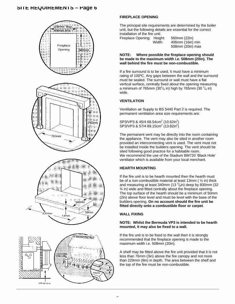
Manual Control Models
If the fire supply cable has not been fitted when wiring theboiler proceed as follows:
Isolate the electrical supply to the boiler including thepermanent live.
Remove the boiler controls assembly as described in theboiler Installation and Servicing Instructions.
The socket should be wired as described in the boilerInstallation and Servicing Instructions.
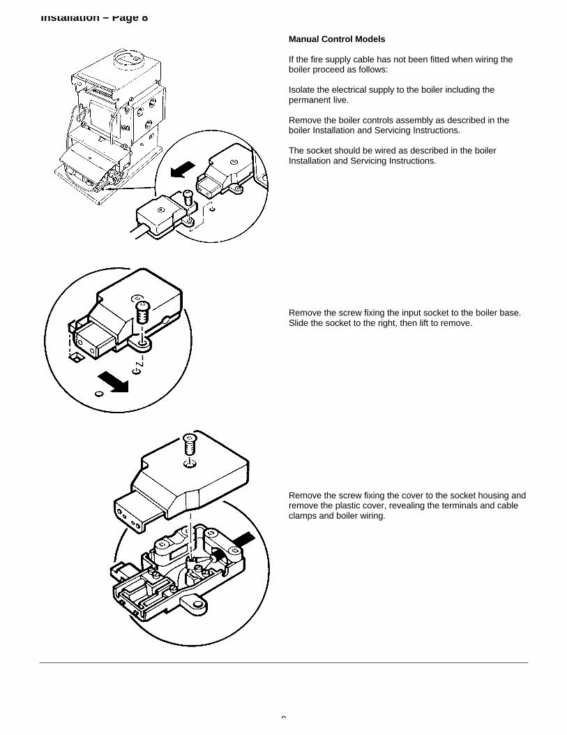
Remove the screw fixing the input socket to the boiler base.Slide the socket to the right, then lift to remove.
Remove the screw fixing the cover to the socket housing andremove the plastic cover, revealing the terminals and cableclamps and boiler wiring.

9
Installation – Page 9
From the plug and cable connection supplied with the fireunit, the following connections should be made, making surethat the appropriate cable clamp is used to hold the cablefirmly.
Connect the blue wire (neutral) to the remaining terminalmarked ‘N’. Connect the brown wire (permanent live) to theremaining terminal marked ‘L2’. Route the green & yellowwire (earth) through the cut-out in the socket housing andconnect it to the earth terminal.
The earth wire should be long enough so that the live andneutral wires will become taut before the earth wire if thecable is pulled.
Refit the socket cover and fix in place with the screw.
Refit the input socket assembly to the boiler base and fix inplace with the securing screw.
Reconnect the controls connection plug to the input socketand again, fix in place with the securing screw.
Clamp the input cable in place using the appropriate clip.

10
Installation – Page 10
Electronic Controls Models
Remove the controls heat shield from its retaining clips.
Isolate the electrical supply to the boiler, including thepermanent live.
Remove the electrical inlet socket from the PCB at the rearleft hand side of the control box.
Remove the socket cover. The socket should be wired asdescribed in the boiler Installation and Servicing Instructions.
Remove the side cable clamp and connect the wire from thefire front kit as indicated:
Brown (live) to LBlue (neutral) to N
Green and Yellow (earth) to
Refit the cable clamp ensuring that the outer insulation issecurely held and refit the socket cover.
Ensure that all cables are routed away from the boilercasing and hood.
11
Installation – Page 11
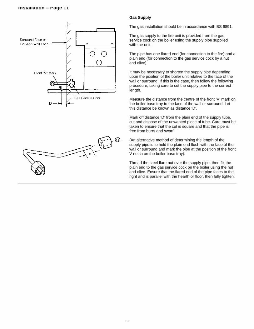
Gas Supply
The gas installation should be in accordance with BS 6891.
The gas supply to the fire unit is provided from the gasservice cock on the boiler using the supply pipe suppliedwith the unit.
The pipe has one flared end (for connection to the fire) and aplain end (for connection to the gas service cock by a nutand olive).
It may be necessary to shorten the supply pipe dependingupon the position of the boiler unit relative to the face of thewall or surround. If this is the case, then follow the followingprocedure, taking care to cut the supply pipe to the correctlength.
Measure the distance from the centre of the front ‘V’ mark onthe boiler base tray to the face of the wall or surround. Letthis distance be known as distance ‘D’.
Mark off distance ‘D’ from the plain end of the supply tube,cut and dispose of the unwanted piece of tube. Care must betaken to ensure that the cut is square and that the pipe isfree from burrs and swarf.
(An alternative method of determining the length of thesupply pipe is to hold the plain end flush with the face of thewall or surround and mark the pipe at the position of the frontV notch on the boiler base tray).
Thread the steel flare nut over the supply pipe, then fix theplain end to the gas service cock on the boiler using the nutand olive. Ensure that the flared end of the pipe faces to theright and is parallel with the hearth or floor, then fully tighten.
12
Installation – Page 12
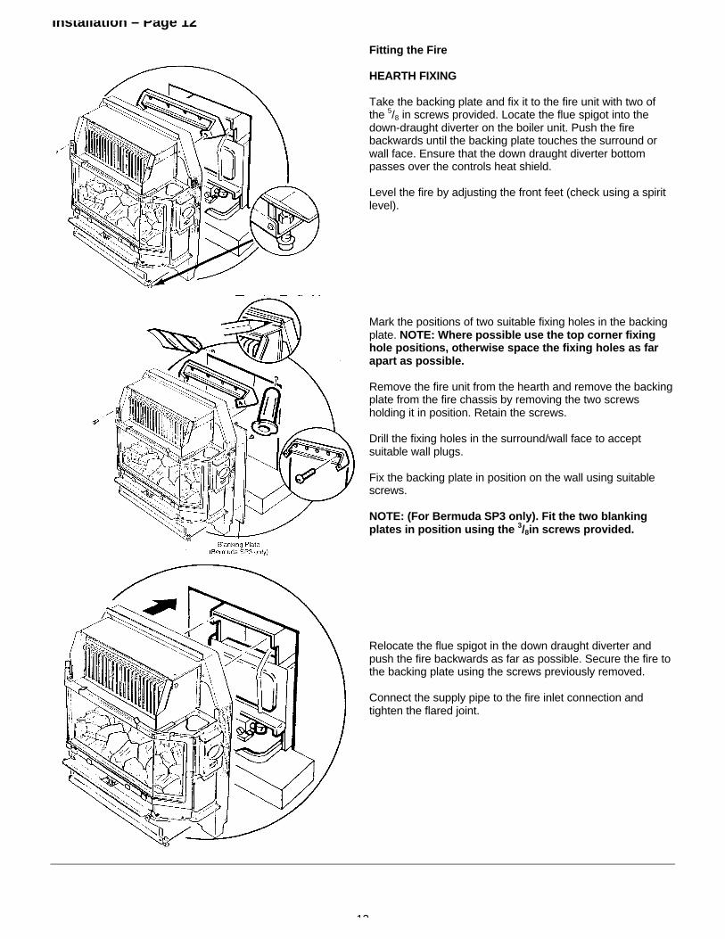
Fitting the Fire
HEARTH FIXING
Take the backing plate and fix it to the fire unit with two ofthe 5/8 in screws provided. Locate the flue spigot into thedown-draught diverter on the boiler unit. Push the firebackwards until the backing plate touches the surround orwall face. Ensure that the down draught diverter bottompasses over the controls heat shield.
Level the fire by adjusting the front feet (check using a spiritlevel).
Mark the positions of two suitable fixing holes in the backingplate. NOTE: Where possible use the top corner fixinghole positions, otherwise space the fixing holes as farapart as possible.
Remove the fire unit from the hearth and remove the backingplate from the fire chassis by removing the two screwsholding it in position. Retain the screws.
Drill the fixing holes in the surround/wall face to acceptsuitable wall plugs.
Fix the backing plate in position on the wall using suitablescrews.
NOTE: (For Bermuda SP3 only). Fit the two blankingplates in position using the 3/8in screws provided.
Relocate the flue spigot in the down draught diverter andpush the fire backwards as far as possible. Secure the fire tothe backing plate using the screws previously removed.
Connect the supply pipe to the fire inlet connection andtighten the flared joint.

13
Installation – Page 13
Wall Fixing
Taking the fire support plate from the fire unit packaging,place it above the boiler base protruding from the fireplaceopening. (On electronic control boilers it will be necessary toremove the inlet plug from the controls). With the screwsprovided, loosely attach the plate to the boiler base using theslots at each side.
Push the support plate backwards until it touches thesurround/wall face and tighten the screws to lock it inposition.
Take the backing plate and fix it to the fire unit with two ofthe 5/8in screws provided. Locate the flue spigot into thedown-draught diverter on the boiler unit. Push the firebackwards until the backing plate touches the surround orwall face.
Level the fire by adjusting the front feet (check using a spiritlevel).
Mark the positions of the available fixing holes in the backingplate. NOTE: Where possible use the top corner fixinghole positions, otherwise space the fixing holes as farapart as possible.
Remove the fire unit from the support plate and remove thebacking plate from the fire chassis by removing the twoscrews holding it in position. Retain the screws.
Drill the fixing holes in the surround/wall face to acceptsuitable wall plugs.
Fix the backing plate in position on the wall using suitablescrews.
NOTE: (For Bermuda SP3 only) Fit the two blankingplates in position using the 3/8in screws provided.
Relocate the flue spigot in the down-draught diverter andpush the fire backwards as far as possible. Secure the fire tothe backing plate using the screws previously removed
Connect the supply pipe to the fire inlet connection andtighten the flared joint.

14
COMMISSIONING THE FIRE – Page 14
Turn the gas service cock to the boiler and fire position.Purge any air from the fire supply pipe. Check for gassoundness from the gas service cock to the fire inletconnection (BS 6891).
Remove the glass frame by disengaging the retainingclamps and lifting away. Remove the polystyrene packingpiece securing the coal bed in position.
Lift the coal bed out and remove from its plastic bag.Carefully place it in position on the burner.
CAUTION: The coal bed is extremely fragile and must behandled accordingly. Gloves must be worn and anyinhalation of the dust should be avoided. Keep the coalsaway from children at all times. Please read theImportant Information section on page 4.
Remove any labels fixed to the glass frame assemblyand clean both sides of the glass panels using a nonabrasive cream cleanser, before replacing the glassframe.
Replace the glass frame and lock in place by engaging theretaining clamps.
Connect the electricity supply to the fire unit by fixing theplug in position.

15
COMMISSIONING THE FIRE – Page 15
Check the electricity supply to the fire unit by switching onthe illumination bulbs. If the bulbs light, switch off andcontinue with commissioning the fire. If the bulbs do not light,isolate the electricity supply and perform preliminaryelectrical system checks before proceeding i.e. earthcontinuity, polarity, resistance to earth etc.
Remove the electrical cover on the right hand side of thechassis by removing the fixing screw.
Release the pressure test point sealing screw and connect apressure gauge in position.
Push in the control knob, turn to the IGNITION position ( )and hold in. Sparking will commence at the ignition electrodeand the pilot will ignite.
Continue to hold the control knob in for a further 15 secondsthen release. The sparking will stop and the pilot will stayalight. If the pilot does not stay alight, repeat the processafter waiting for 2 minutes. (If the pilot still fails to remainalight, refer to the fault finding chart).

16
COMMISSIONING THE FIRE – Page 16
Check the setting pressure at position 4. No adjustment tothe setting pressure is possible.
Turn the control knob to the ‘OFF’ ( ) position.
Disconnect the pressure gauge and replace the pressuretest point sealing screw, ensuring a gas-tight seal.
Refit the electrical cover.
SPILLAGE DETECTION
A test for clearance of flue products is only possible from theleft hand side and must be made as follows: Ensure that alldoors and windows in the room are closed. (If there is anextractor fan or ceiling fan in the room or any adjoiningroom, the check for spillage must be performed with thefan turned on and any interconnecting doors open.)Ignite the fire and turn to setting 4. After running for 5minutes take a lighted smoke match and insert it into theboiler down-draught diverter as shown.
WARNING
CARE MUST BE TAKEN TO AVOID TOUCHING HOTPANELS AT THIS POINT.
If the majority of the smoke is not drawn into the chimney,then spillage of combustion products is indicated and furtherinvestigations must be carried out.
Repeat the procedure with both the boiler and the fire alight(the boiler having been alight for 5 minutes).

17
FITTING THE OUTER CASE – Page 17
Bermuda VP3
Turn off the fire and fit the outer case components asfollows:
Remove the fender front from the hearth assembly by pullingforward.
Engage the hearth assembly on the side ledges as shownand push home as far as possible. Adjust the feet to touchthe fireplace hearth. Fix the hearth assembly in positionusing the two No 8 x 5/8in screws in the front and the two M4x 8mm thread former screws in the sides.
Hang the left and right hand side doors on the fittings asshown and close the doors, ensuring that they lock inposition.
Fix the canopy by lowering it into position over the top edgeand then by gently easing the sides inwards, push home tolock in place.
Locate the fender front in position at the front of the hearthassembly and push home.
Instruct the user in the operation of the fire controls andhand over the user’s instructions and installation instructions,giving advice on the necessity of regular servicing.

18
Fitting The Outer Case – Page 18
Bermuda SP3
Turn off the fire and fit the outer case components asfollows:
Engage the hearth by guiding the locating pins through theholes in the innercase and sliding forward on the side ledgesas far as possible. Fix the hearth in position using the two 3/8in screws in the sides.
Hang the left and right hand side doors on the fittings asshown, leaving them open.
Fix the canopy by guiding the bottom edge onto the doorpins and then by tilting the back edge over the locating lip onthe innercase. Close the doors ensuring they lock in place.
Instruct the user in the operation of the fire controls andhand over the user’s instructions and installation instructions,giving advice on the necessity of regular servicing.

19
ANNUAL SERVICING – Page 19
Bermuda VP3
For reasons of safety and economy, it is important to serviceboth the fire and boiler units annually. Before servicingplease read the Important Information section on page 4.
NOTE: Before attempting to service the appliance,ensure that the fire is COLD.
Important: It is possible that some soot may be depositedon the coals after use. This is acceptable providing it is notallowed to accumulate.
CAUTION: The coal bed is extremely fragile and mustbe handled accordingly. Gloves should be worn and anyinhalation of the dust should be avoided. Keep the coalsaway from children at all times.
ISOLATE THE GAS AND ELECTRICITY SUPPLY TO THEBOILER AND FIRE UNITS INCLUDING THE PERMANENTLIVE.
Remove the canopy by gently easing the sides inwards andpulling the bottom edge forward, then lift the canopyupwards and away from the locating lip.
Remove the left and right hand side doors firstly by openingthem and then lifting away from their mountings.
Remove the fender front by pulling forward.
Remove the hearth assembly by removing the fixing screwsand sliding it forward and away from the chassis.

20
ANNUAL SERVICING – Page 20
Bermuda SP3
For reasons of safety and economy, it is important to serviceboth the fire and boiler units annually. Before servicingplease read the Important Information section on page 4.
NOTE: Before attempting to service the appliance,ensure that the fire is COLD.
Important: It is possible that some soot may be depositedon the coals after use. This is acceptable providing it is notallowed to accumulate.
CAUTION: The coal bed is extremely fragile and mustbe handled accordingly. Gloves should be worn and anyinhalation of the dust should be avoided. Keep the coalsaway from children at all times.
ISOLATE THE GAS AND ELECTRICITY SUPPLY TO THEBOILER AND FIRE UNITS INCLUDING THE PERMANENTLIVE.
Remove the canopy firstly by opening the left and right handside doors, then lift the canopy by the bottom edge upwardsand away from the locating lip.
Remove the left and right hand side doors by lifting themfrom their mountings.
Remove the hearth by removing the fixing screws and slidingthe hearth assembly forward and away from the chassis.
21
ANNUAL SERVICING – Page 21
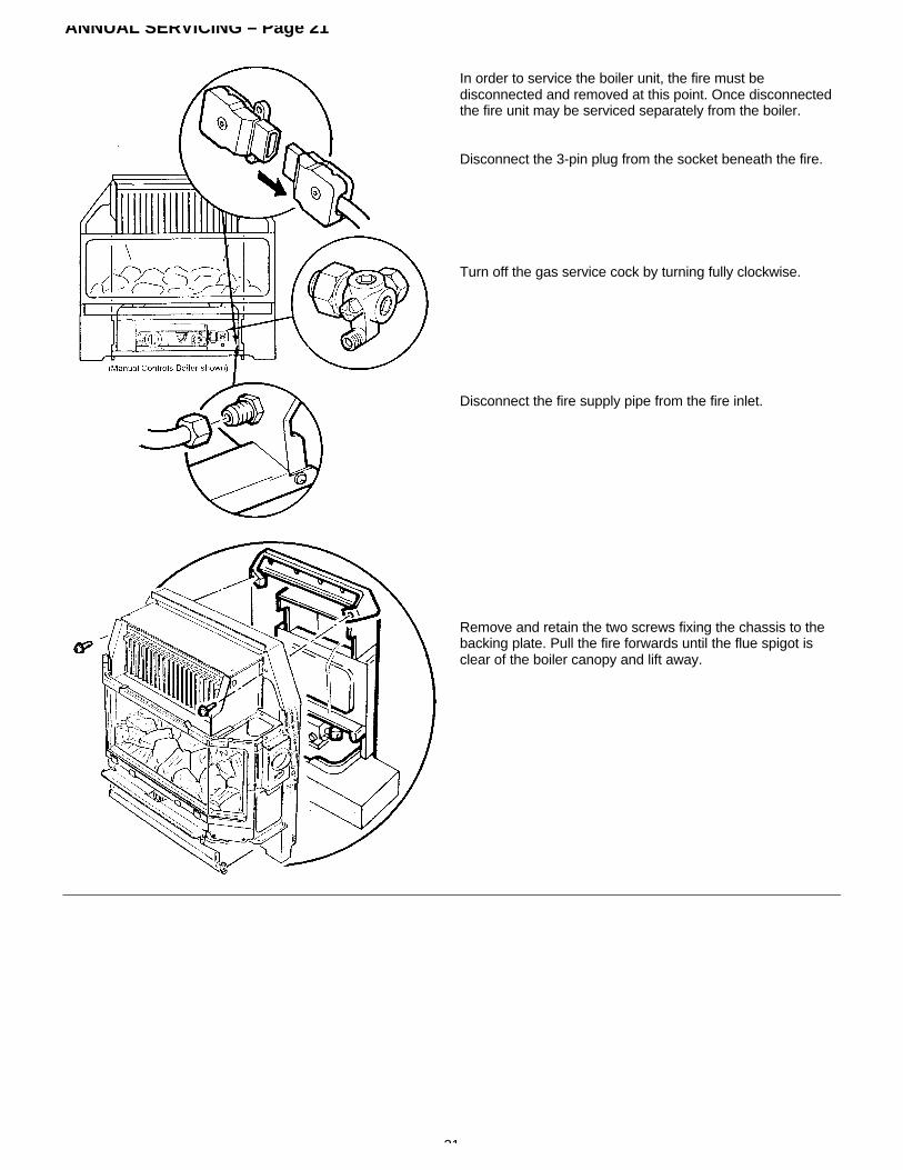
In order to service the boiler unit, the fire must bedisconnected and removed at this point. Once disconnectedthe fire unit may be serviced separately from the boiler.
Disconnect the 3-pin plug from the socket beneath the fire.
Turn off the gas service cock by turning fully clockwise.
Disconnect the fire supply pipe from the fire inlet.
Remove and retain the two screws fixing the chassis to thebacking plate. Pull the fire forwards until the flue spigot isclear of the boiler canopy and lift away.

22
ANNUAL SERVICING – Page 22
Ensuring that the glass frame is cold, disengage theretaining clamps and lift the frame away.
Remove the coal bed by carefully lifting away from thelocating pins and place to one side.
Cleaning the Pilot / A.S.D. Assembly
WARNING: The A.S.D. pilot assembly must not be adjustedin any way.
The A.S.D. must not be altered so that it will not operate orbe bypassed in any way.
Ensure that the pilot burner aeration hole is free from lint,debris etc.
If necessary clean the electrode and target, and check thatthe spark gap is 2.5 - 4.0mm.
The thermocouple cannot be changed as an individualcomponent. The complete assembly must be replaced in theevent of one or other component failure(s).
Only use a Genuine Baxi Spare Part.
23
ANNUAL SERVICING – Page 23
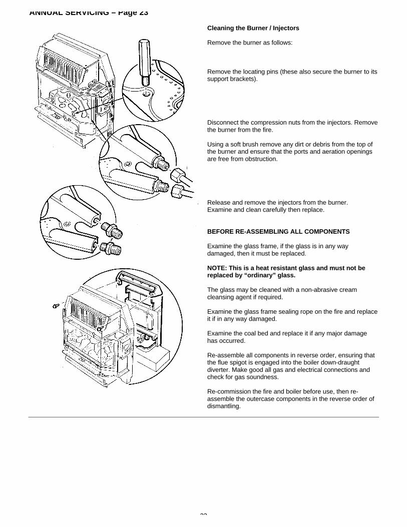
Cleaning the Burner / Injectors
Remove the burner as follows:
Remove the locating pins (these also secure the burner to itssupport brackets).
Disconnect the compression nuts from the injectors. Removethe burner from the fire.
Using a soft brush remove any dirt or debris from the top ofthe burner and ensure that the ports and aeration openingsare free from obstruction.
Release and remove the injectors from the burner.Examine and clean carefully then replace.
BEFORE RE-ASSEMBLING ALL COMPONENTS
Examine the glass frame, if the glass is in any waydamaged, then it must be replaced.
NOTE: This is a heat resistant glass and must not bereplaced by “ordinary” glass.
The glass may be cleaned with a non-abrasive creamcleansing agent if required.
Examine the glass frame sealing rope on the fire and replaceit if in any way damaged.
Examine the coal bed and replace it if any major damagehas occurred.
Re-assemble all components in reverse order, ensuring thatthe flue spigot is engaged into the boiler down-draughtdiverter. Make good all gas and electrical connections andcheck for gas soundness.
Re-commission the fire and boiler before use, then re-assemble the outercase components in the reverse order ofdismantling.
24
CHANGING COMPONENTS – Page 24
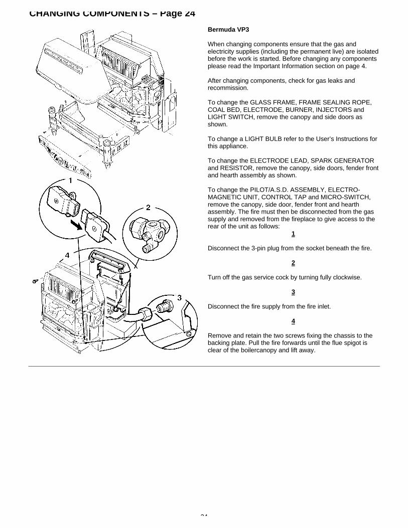
Bermuda VP3
When changing components ensure that the gas andelectricity supplies (including the permanent live) are isolatedbefore the work is started. Before changing any componentsplease read the Important Information section on page 4.
After changing components, check for gas leaks andrecommission.
To change the GLASS FRAME, FRAME SEALING ROPE,COAL BED, ELECTRODE, BURNER, INJECTORS andLIGHT SWITCH, remove the canopy and side doors asshown.
To change a LIGHT BULB refer to the User’s Instructions forthis appliance.
To change the ELECTRODE LEAD, SPARK GENERATORand RESISTOR, remove the canopy, side doors, fender frontand hearth assembly as shown.
To change the PILOT/A.S.D. ASSEMBLY, ELECTRO-MAGNETIC UNIT, CONTROL TAP and MICRO-SWITCH,remove the canopy, side door, fender front and hearthassembly. The fire must then be disconnected from the gassupply and removed from the fireplace to give access to therear of the unit as follows:
1
Disconnect the 3-pin plug from the socket beneath the fire.
2
Turn off the gas service cock by turning fully clockwise.
3
Disconnect the fire supply from the fire inlet.
4
Remove and retain the two screws fixing the chassis to thebacking plate. Pull the fire forwards until the flue spigot isclear of the boilercanopy and lift away.

25
CHANGING COMPONENTS – Page 25
Bermuda SP3
When changing components ensure that the gas andelectricity supplies (including the permanent live) are isolatedbefore the work is started. Before changing any componentsplease read the Important Information section on page 4.
After changing components, check for gas leaks andrecommission.
To change the GLASS FRAME, FRAME SEALING ROPE,COAL BED, ELECTRODE, BURNER, INJECTORS andLIGHT SWITCH, remove the canopy and side doors asshown.
To change a LIGHT BULB refer to the User’s Instructions forthis appliance.
To change the ELECTRODE LEAD, SPARK GENERATORand RESISTOR, remove the canopy, side doors and hearthas shown.
To change the PILOT/A.S.D. ASSEMBLY, ELECTRO-MAGNETIC UNIT, CONTROL TAP and MICRO-SWITCH,remove the canopy, side door and hearth. The fire must thenbe disconnected from the gas supply and removed from thefireplace to give access to the rear of the unit as follows:
1
Disconnect the 3-pin plug from the socket beneath the fire.
2
Turn off the gas service cock by turning fully clockwise.
3
Disconnect the fire supply from the fire inlet.
4
Remove and retain the two screws fixing the chassis to thebacking plate. Pull the fire forwards until the flue spigot isclear of the boiler canopy and lift away.

26
CHANGING COMPONENTS – Page 26
Glass Frame
1
Ensure that the glass panel is cold. Disengage the retainingclamps.
Lift the frame away.
Fix the new glass frame in position and engage the retainingclamps. Re-assemble the components in the reverse orderto dismantling.
Frame Sealing Rope
1
Ensure that the glass panel is cold. Disengage the retainingclamps.
Lift the frame away.
2
Pull the old rope seal out of the locating channel and releasethe glass locating brackets.
Fit the new seal, starting at the centre, tuck well into thelocating channel. Ensure that there is an equal amount ofseal free at either end of the channel. Secure the glasslocating brackets.
Fix the glass frame in position and engage the retainingclamps. Re-assemble the components in the reverse orderto dismantling.
Check that the seal between the rope and the glass frame isgood.
Coal Bed
1
Ensure that the glass panel is cold. Disengage the retainingclamps.
Lift the frame away.
3
Lift the coal bed away from the locating pins.
Carefully fit the new coal bed in position on the locating pins.Fix the glass frame in position and engage the retainingclamps. Re-assemble the components in the reverse orderto dismantling.CAUTION: The coal bed is extremely fragile and must behandled accordingly. Gloves should be worn and anyinhalation of the dust should be avoided. Keep the coalsaway from children at all times. Please read theImportant Information section on page 4.

27
CHANGING COMPONENTS – Page 27
Burner and Injectors
1
Ensure that the glass panel is cold.Disengage the retaining clamps and lift the frame away.
2
Lift the coal bed away from the locating pins and place toone side.
3
Remove the locating pinssecuring the burner to its support brackets.
4Disconnect the compression nuts from the injectors andcarefully remove the burner to avoid damaging the pilotassembly.
5
Remove the injectors from the old burner and fit them intothe new burner or if required fit new injectors (flat end in theburner) taking care not to over tighten them in theirmountings.
Re-assemble the components in the reverse order todismantling.

28
CHANGING COMPONENTS – Page 28
Ensure that the electricity supply to the fire unit isisolated.
1
Remove the control knob by pulling from the spindle.
2
Remove the two screws holding the bezel in place.
3
Note the orientation of the two electrical connections anddisconnect from the switch. Remove the bezel.
4
Press together the retaining arms on the rear of the switchand remove from the bezel.
Fit the new switch in place, ensure that the orientation of theswitch is correct. (i.e. with the ‘O’ symbol towards the front ofthe fire.) and make good the electrical connections.
Re-assemble the components in the reverse order todismantling.
29
CHANGING COMPONENTS – Page 29
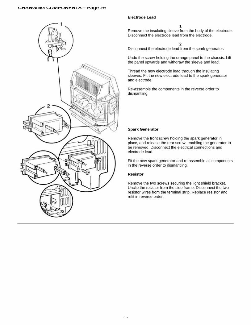
Electrode Lead
1Remove the insulating sleeve from the body of the electrode.Disconnect the electrode lead from the electrode.
2Disconnect the electrode lead from the spark generator.
Undo the screw holding the orange panel to the chassis. Liftthe panel upwards and withdraw the sleeve and lead.
Thread the new electrode lead through the insulatingsleeves. Fit the new electrode lead to the spark generatorand electrode.
Re-assemble the components in the reverse order todismantling.
Spark Generator
Remove the front screw holding the spark generator inplace, and release the rear screw, enabling the generator tobe removed. Disconnect the electrical connections andelectrode lead.
Fit the new spark generator and re-assemble all componentsin the reverse order to dismantling.
Resistor
Remove the two screws securing the light shield bracket.Unclip the resistor from the side frame. Disconnect the tworesistor wires from the terminal strip. Replace resistor andrefit in reverse order.

30
CHANGING COMPONENTS – Page 30
Pilot / ASD Assembly
WARNING: The PiIot / A.S.D. assembly must not beadjusted in any way.
The A.S.D. must not be altered so that it will not operateor be bypassed in any way.
The thermocouple cannot be changed as an individualcomponent. The complete assembly must be replaced inthe event of one or other component failure(s).
Only use a Genuine Baxi Spare Part.
1
Remove the lead from the electrode.
2
Undo the pilot feed pipe from the assembly.
4
Undo the thermocouple from the gas tap.
3
Remove the screws holding the pilot assembly bracket to thefire chassis. Unclip the thermocouple from the fire chassis.Withdraw the pilot assembly and bracket.
Remove the screw holding the assembly to the bracket.
Re-assemble all components in the reverse order todismantling.
Electro-Magnetic Unit
4
Release the thermocouple from the control tap byunscrewing the retaining nut.
5
Release the Electro-Magnetic Unit retaining nut and removethe unit from the control tap. Fit the new Electro-MagneticUnit and replace the retaining nut.
Fix the thermocouple in position taking care not toovertighten the retaining nut. Re-assemble all components inreverse order to dismantling.
Check for gas leaks.

31
CHANGING COMPONENTS – Page 31
Control Tap and Micro-Switch
1
Remove the control knob by pulling from the spindle.
Remove the two screws holding the bezel in place.
Disconnect the two electrical connections from the lightswitch, taking note of their orientation. Remove the bezel.
2
Release the thermocouple from the control tap byunscrewing the retaining nut.
Disconnect the two electrical connections from the microswitch.
Release the nut-and-olive connections on the control tapbody and disconnect the gas pipes from the control tap.
Disconnect the gas inlet at the control tap by releasing thecompression fitting.
3
Release the locknut fixing the control tap to the chassis.Access to the locknut may be gained through the bezellocation.
Withdraw the control tap from the fire.
4
At this point change the micro-switch if required byremoving the circlip holding it in position on the control tap.
Fit the new micro-switch or the new control tap in reverseorder.
Make good all gas and electrical connections. Temporarilyreconnect electricity supply. Light the fire, turn off theelectricity supply and check all joints for gas soundness.Turn the fire off. Re-assemble all components in reverseorder to dismantling.

32-33
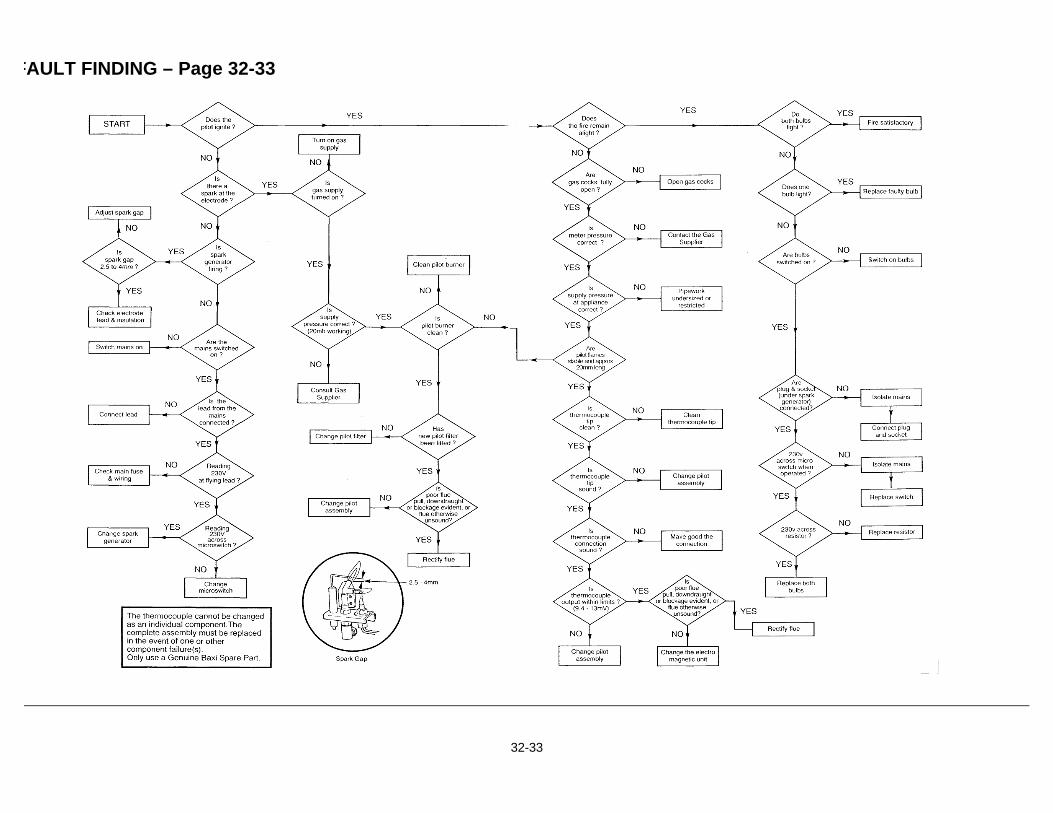
FAULT FINDING – Page 32-33

34
SHORT PARTS LIST – Page 34
Key Nos G.C. Description ManufacturersSP3 VP3 No Part No
15 17 156 036 Glass and Frame Assy 225391
- 48 156 233 Knob Control SP3 233466
46 - 156 431 Knob Control VP3 236394
50 52 156 063 Seal Frame Glass Rope 226876
80 82 378 912 Pilot/A.S.D. Assembly 235601
68 70 156 300 Gas Tap 234098
69 71 E01 617 Electro Magnetic Unit 239413
70 72 156 095 Micro Switch Assy 227761
78 80 156 094 Burner 225400
79 81 156 432 Coal Bed 236103
81 83 397 681 Injector Burner FO2 226910
82 84 378 988 Spark Generator 233254
87 91 387 916 Electrode Lead (2.8mm) 236184
83 85 386 129 Resistor 68 228955
72 74 205 723 Pilot Filter 082412
The following components are unique to the VP3 PROPANEappliance only:
Key Nos G.C. Description ManufacturersNo Part No
70 E00 855 Gas Tap (LPG) 237082
80 E00 857 Burner (LPG) 237433
81 E00 856 Coal Bed (LPG) 237432
83 387 857 Injector Burner (LPG) 228486
82 E00 858 Pilot/A.S.D. 237079Assembly (LPG)

35
PROPANE Cat II 2H3P – Page 35Supplementary Instructions
Heat InputkW
Btu/h
Heat InputkW
Btu/h
High
6.05
20,642
Med
3.35
11,430
Med-High
5.34
18,220
Low
2.47
8,427
BERMUDA VP3 - G.C.No 37 077 72GAS TYPE G31
These supplementary instructions should be read inconjunction with the Fire Installation and ServicingInstructions and cover certain features unique to thePropane appliance.
This model to be used only with the Bermuda 553 Propane.
Heat OutputkW
Btu/h
Supply Pressurembar
in wg
Setting Pressurembar
in wg
High
3.63
12,385
37
14.8
Cold
34.2 ± 1.5
13.7±0.6
The Heat Input, Heat Output and Setting Pressures given inthe Instructions Booklet do not apply to the Propaneappliance. Refer to the table opposite.
Propane appliances can be converted to operate onNatural Gas if required.A conversion kit is available, Baxi Part No 247064.
Burner Removal
(See page 27 and read instruction 4 in conjunction with theparagraph below.)
The left hand locating pin does not secure the burner to thesupport bracket. To remove the burner, unscrew the righthand locating pin and the set screw at the left hand side.
Burner Replacement
When replacing the burner remove the left hand locating pinfrom the old burner and refit to the new burner.
(See page 27 for re-assembling all components in thereverse order to dismantling.)
36
Renewal Firefront – Page 36
It is important that the existing installation is correct and thatthe flue is performing satisfactorily. Any remedial worknecessary should be completed before the new appliance iscommissioned. Please read theImportant Information section on page 4.
WARNING: Renewal firefronts are fitted with anAtmospheric Sensing Device (A.S.D.). If they areinstalled in conjunction with a boiler NOT fitted with anA.S.D. (i.e. 401, 552, 45/3 & 57/3), under adverse flueconditions the boiler WILL NOT shut down.
NOTE: A permanent live is required for correct operation ofthe firefront.
Additional Installation Instructions
Bermuda VP3 Renewal G.C.No 37 075 04ABermuda SP3 Renewal G.C.No 37 075 05A
The kit supplied with Renewal appliances provides all thenecessary components to fit a Baxi Bermuda VP3 Renewal& Baxi Bermuda SP3 Renewal firefront to the followingBermuda Boilers.
The Renewal Fires may use with the following Boilers:
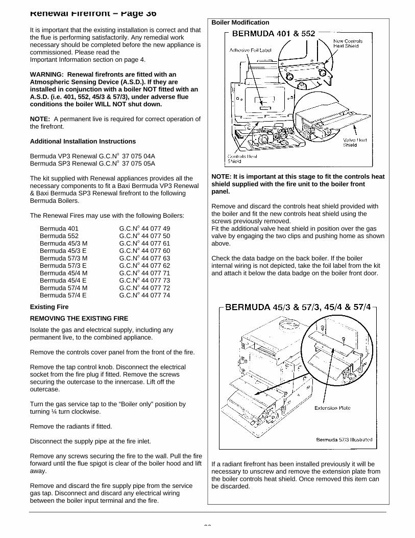
Boiler Modification
NOTE: It is important at this stage to fit the controls heatshield supplied with the fire unit to the boiler frontpanel.
Remove and discard the controls heat shield provided withthe boiler and fit the new controls heat shield using thescrews previously removed.
Bermuda 401Bermuda 552Bermuda 45/3 MBermuda 45/3 EBermuda 57/3 MBermuda 57/3 EBermuda 45/4 MBermuda 45/4 EBermuda 57/4 MBermuda 57/4 E
G.C.No 44 077 49G.C.No 44 077 50G.C.No 44 077 61G.C.No 44 077 60G.C.No 44 077 63G.C.No 44 077 62G.C.No 44 077 71G.C.No 44 077 73G.C.No 44 077 72G.C.No 44 077 74
Fit the additional valve heat shield in position over the gasvalve by engaging the two clips and pushing home as shownabove.
Check the data badge on the back boiler. If the boilerinternal wiring is not depicted, take the foil label from the kitand attach it below the data badge on the boiler front door.
Existing Fire
REMOVING THE EXISTING FIRE
Isolate the gas and electrical supply, including anypermanent live, to the combined appliance.
Remove the controls cover panel from the front of the fire.
Remove the tap control knob. Disconnect the electricalsocket from the fire plug if fitted. Remove the screwssecuring the outercase to the innercase. Lift off theoutercase.
Turn the gas service tap to the “Boiler only” position byturning ¼ turn clockwise.
Remove the radiants if fitted.
Disconnect the supply pipe at the fire inlet.
Remove any screws securing the fire to the wall. Pull the fireforward until the flue spigot is clear of the boiler hood and liftaway.
Remove and discard the fire supply pipe from the servicegas tap. Disconnect and discard any electrical wiringbetween the boiler input terminal and the fire.
If a radiant firefront has been installed previously it will benecessary to unscrew and remove the extension plate fromthe boiler controls heat shield. Once removed this item canbe discarded.
37
Renewal Firefront – Page 37
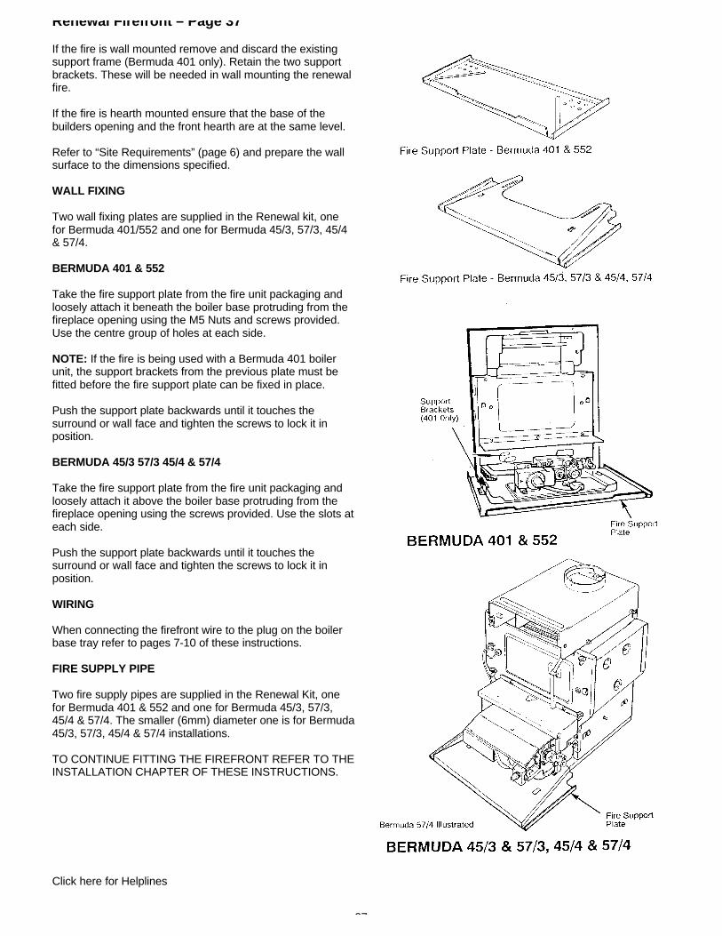
If the fire is wall mounted remove and discard the existingsupport frame (Bermuda 401 only). Retain the two supportbrackets. These will be needed in wall mounting the renewalfire.
If the fire is hearth mounted ensure that the base of thebuilders opening and the front hearth are at the same level.
Refer to “Site Requirements” (page 6) and prepare the wallsurface to the dimensions specified.
WALL FIXING
Two wall fixing plates are supplied in the Renewal kit, onefor Bermuda 401/552 and one for Bermuda 45/3, 57/3, 45/4& 57/4.
BERMUDA 401 & 552
Take the fire support plate from the fire unit packaging andloosely attach it beneath the boiler base protruding from thefireplace opening using the M5 Nuts and screws provided.Use the centre group of holes at each side.
NOTE: If the fire is being used with a Bermuda 401 boilerunit, the support brackets from the previous plate must befitted before the fire support plate can be fixed in place.
Push the support plate backwards until it touches thesurround or wall face and tighten the screws to lock it inposition.
BERMUDA 45/3 57/3 45/4 & 57/4
Take the fire support plate from the fire unit packaging andloosely attach it above the boiler base protruding from thefireplace opening using the screws provided. Use the slots ateach side.
Push the support plate backwards until it touches thesurround or wall face and tighten the screws to lock it inposition.
WIRING
When connecting the firefront wire to the plug on the boilerbase tray refer to pages 7-10 of these instructions.
FIRE SUPPLY PIPE
Two fire supply pipes are supplied in the Renewal Kit, onefor Bermuda 401 & 552 and one for Bermuda 45/3, 57/3,45/4 & 57/4. The smaller (6mm) diameter one is for Bermuda45/3, 57/3, 45/4 & 57/4 installations.
TO CONTINUE FITTING THE FIREFRONT REFER TO THEINSTALLATION CHAPTER OF THESE INSTRUCTIONS.
Click here for Helplines