Battery Management System - High-Voltage applications Installation
36
Installation Manual Battery Manager Main Module (AP9922) & Expansion Module (AP9922S) 990-1649F-001 Publication Date: December 2015
Transcript of Battery Management System - High-Voltage applications Installation

Installation Manual
Battery Manager
Main Module (AP9922) & Expansion Module (AP9922S)
990-1649F-001Publication Date: December 2015

Schneider Electric Legal DisclaimerThe information presented in this manual is not warranted by Schneider Electric to be authoritative, error free,
or complete. This publication is not meant to be a substitute for a detailed operational and site specific
development plan. Therefore, Schneider Electric assumes no liability for damages, violations of codes,
improper installation, system failures, or any other problems that could arise based on the use of this
Publication.
The information contained in this Publication is provided as is and has been prepared solely for the purpose of
evaluating data center design and construction. This Publication has been compiled in good faith by Schneider
Electric. However, no representation is made or warranty given, either express or implied, as to the
completeness or accuracy of the information this Publication contains.
IN NO EVENT SHALL SCHNEIDER ELECTRIC, OR ANY PARENT, AFFILIATE OR SUBSIDIARY COMPANY
OF SCHNEIDER ELECTRIC OR THEIR RESPECTIVE OFFICERS, DIRECTORS, OR EMPLOYEES BE
LIABLE FOR ANY DIRECT, INDIRECT, CONSEQUENTIAL, PUNITIVE, SPECIAL, OR INCIDENTAL
DAMAGES (INCLUDING, WITHOUT LIMITATION, DAMAGES FOR LOSS OF BUSINESS, CONTRACT,
REVENUE, DATA, INFORMATION, OR BUSINESS INTERRUPTION) RESULTING FROM, ARISING OUT,
OR IN CONNECTION WITH THE USE OF, OR INABILITY TO USE THIS PUBLICATION OR THE CONTENT,
EVEN IF SCHNEIDER ELECTRIC HAS BEEN EXPRESSLY ADVISED OF THE POSSIBILITY OF SUCH
DAMAGES. SCHNEIDER ELECTRIC RESERVES THE RIGHT TO MAKE CHANGES OR UPDATES WITH
RESPECT TO OR IN THE CONTENT OF THE PUBLICATION OR THE FORMAT THEREOF AT ANY TIME
WITHOUT NOTICE.
Copyright, intellectual, and all other proprietary rights in the content (including but not limited to software, audio,
video, text, and photographs) rests with Schneider Electric or its licensors. All rights in the content not expressly
granted herein are reserved. No rights of any kind are licensed or assigned or shall otherwise pass to persons
accessing this information.
This Publication shall not be for resale in whole or in part.
Table of Contents
Introduction ............................................................................................................1Inventory (AP9922) . . . . . . . . . . . . . . . . . . . . . . . . . . . . . . . . . . . . . . . . . . . . . . . .1Inventory (AP9922S) . . . . . . . . . . . . . . . . . . . . . . . . . . . . . . . . . . . . . . . . . . . . . .1Optional Equipment . . . . . . . . . . . . . . . . . . . . . . . . . . . . . . . . . . . . . . . . . . . . . . .2Additional Documentation . . . . . . . . . . . . . . . . . . . . . . . . . . . . . . . . . . . . . . . . . . .2Wire Harness . . . . . . . . . . . . . . . . . . . . . . . . . . . . . . . . . . . . . . . . . . . . . . . . . . . .2Inspection . . . . . . . . . . . . . . . . . . . . . . . . . . . . . . . . . . . . . . . . . . . . . . . . . . . . . . .2Please Recycle . . . . . . . . . . . . . . . . . . . . . . . . . . . . . . . . . . . . . . . . . . . . . . . . . . .2
Important Safety Information..................................................................................3Please Note . . . . . . . . . . . . . . . . . . . . . . . . . . . . . . . . . . . . . . . . . . . . . . . . . . . . .3Battery Safety . . . . . . . . . . . . . . . . . . . . . . . . . . . . . . . . . . . . . . . . . . . . . . . . . . . .4When Installing the Battery Manager: . . . . . . . . . . . . . . . . . . . . . . . . . . . . . . . . .4Lockout/Tagout the UPS . . . . . . . . . . . . . . . . . . . . . . . . . . . . . . . . . . . . . . . . . . .5
System Overview...................................................................................................6Main Module (AP9922). . . . . . . . . . . . . . . . . . . . . . . . . . . . . . . . . . . . . . . . . . . . . . . . . . . .6
Front Panel . . . . . . . . . . . . . . . . . . . . . . . . . . . . . . . . . . . . . . . . . . . . . . . . . . . . . .6Rear Panel . . . . . . . . . . . . . . . . . . . . . . . . . . . . . . . . . . . . . . . . . . . . . . . . . . . . . .7
Expansion Module (AP9922S) . . . . . . . . . . . . . . . . . . . . . . . . . . . . . . . . . . . . . . . . . . . . . .8
Front Panel . . . . . . . . . . . . . . . . . . . . . . . . . . . . . . . . . . . . . . . . . . . . . . . . . . . . . .8Rear Panel . . . . . . . . . . . . . . . . . . . . . . . . . . . . . . . . . . . . . . . . . . . . . . . . . . . . . .8
Installation..............................................................................................................9Overview . . . . . . . . . . . . . . . . . . . . . . . . . . . . . . . . . . . . . . . . . . . . . . . . . . . . . . . .9
Install the Battery Manager. . . . . . . . . . . . . . . . . . . . . . . . . . . . . . . . . . . . . . . . . . . . . . . . .9
Rubber Feet Method . . . . . . . . . . . . . . . . . . . . . . . . . . . . . . . . . . . . . . . . . . . . . . .9Battery Cabinet Method . . . . . . . . . . . . . . . . . . . . . . . . . . . . . . . . . . . . . . . . . . . .9Connect the Ground Wire . . . . . . . . . . . . . . . . . . . . . . . . . . . . . . . . . . . . . . . . . .11
Configure the DIP Switches . . . . . . . . . . . . . . . . . . . . . . . . . . . . . . . . . . . . . . . . . . . . . . .12
Install the Temperature Sensor Assembly . . . . . . . . . . . . . . . . . . . . . . . . . . . . . . . . . . . .13
Install the Current Sensor. . . . . . . . . . . . . . . . . . . . . . . . . . . . . . . . . . . . . . . . . . . . . . . . .14
Connect Multiple Battery Manager Modules. . . . . . . . . . . . . . . . . . . . . . . . . . . . . . . . . . .16
Install the Wire Harness . . . . . . . . . . . . . . . . . . . . . . . . . . . . . . . . . . . . . . . . . . . . . . . . . .17
Quick Configuration (Main module AP9922)........................................................19Overview . . . . . . . . . . . . . . . . . . . . . . . . . . . . . . . . . . . . . . . . . . . . . . . . . . . . . . .19
TCP/IP Configuration Introduction . . . . . . . . . . . . . . . . . . . . . . . . . . . . . . . . . . . . . . . . . .19
Local TCP/IP Configuration . . . . . . . . . . . . . . . . . . . . . . . . . . . . . . . . . . . . . . . . . . . . . . .20
Serial Port / Local Access to the Command Console . . . . . . . . . . . . . . . . . . . . .20
Remote TCP/IP Configuration . . . . . . . . . . . . . . . . . . . . . . . . . . . . . . . . . . . . . . . . . . . . .21
Remote TCP/IP Configuration Using BOOTP & DHCP Server . . . . . . . . . . . . .21Remote TCP/IP Configuration Using Device IP Configuration Wizard . . . . . . . .22Remote TCP/IP Configuration Using ARP Command . . . . . . . . . . . . . . . . . . . .23
Configure Modbus . . . . . . . . . . . . . . . . . . . . . . . . . . . . . . . . . . . . . . . . . . . . . . . . . . . . . .24
Modbus Pin-out and Baud Rate . . . . . . . . . . . . . . . . . . . . . . . . . . . . . . . . . . . . .24Using the Web Interface . . . . . . . . . . . . . . . . . . . . . . . . . . . . . . . . . . . . . . . . . . .24
Access a Configured Battery Manager. . . . . . . . . . . . . . . . . . . . . . . . . . . . . . . . . . . . . . .25
Overview . . . . . . . . . . . . . . . . . . . . . . . . . . . . . . . . . . . . . . . . . . . . . . . . . . . . . . .25Web Interface . . . . . . . . . . . . . . . . . . . . . . . . . . . . . . . . . . . . . . . . . . . . . . . . . . .25Telnet or Secure SHell (SSH) . . . . . . . . . . . . . . . . . . . . . . . . . . . . . . . . . . . . . . .26Simple Network Management Protocol (SNMP) . . . . . . . . . . . . . . . . . . . . . . . . .26FTP and SCP . . . . . . . . . . . . . . . . . . . . . . . . . . . . . . . . . . . . . . . . . . . . . . . . . . .27
Battery Manager - Installation Manual i

Upgrade Firmware . . . . . . . . . . . . . . . . . . . . . . . . . . . . . . . . . . . . . . . . . . . . . . . . . . . . . .27
Calibration ........................................................................................................... 28Calibration of the Battery Manager . . . . . . . . . . . . . . . . . . . . . . . . . . . . . . . . . . .28
Specifications ...................................................................................................... 29
Battery Manager - Installation Manualii

IntroductionThe Schneider Electric Battery Manager can connect up to 244 lead-acid batteries or 375 nickel-cadmium batteries per string. The maximum string voltage allowed for the Battery Manager is 560Vdc nominal (600Vdc absolute maximum). The Battery Manager provides battery management for nominal 2V, 4V, 8V or 12V lead-acid batteries; or 1.2V or 2.4V nickel-cadmium batteries.
There are 2 types of Battery Managers:
• AP9922: Main module• AP9922S: Expansion module
The Main module, AP9922, is always the first module in the system. Expansion modules, AP9922S, are used to extend the number of batteries in a string to be managed.
Each Battery Manager - AP9922 or AP9922S - can receive up to 2 wire harnesses. Each wire harness connects up to 32 batteries to the Battery Manager.
The Main module is the module that collects the data from the 64 batteries it is connected to, and also from the other batteries in the string when Expansion modules are connected. The Main module processes the data and sends notifications and alarms via the Network Management Card.
The Battery Manager can be used with Double conversion and Delta conversion UPS.
For a Delta conversion UPS configuration (or Double conversion UPS with split string configuration), the string of batteries is split into two half strings: a positive string and a negative string of batteries. Each half string must be treated independently and managed by one main module AP9922. Additional expansion modules AP9922S can be connected to the main module if the number of batteries on the string requires it (more than 64).
For more information on the features and capabilities of the Battery Manager, see the Battery Manager User Guide, available on www.schneider-electric.com.
NOTE: Do not turn on the power to the system until the DIP switches are configured and the wire harnesses are connected to the Battery Manager and the batteries.
Inventory (AP9922)
Inventory (AP9922S)
Quantity Item
1 Battery Manager Main module (with internal Network Management capability)
1 Configuration cable (part number 940-0103A)
1 Temperature sensor assembly
1 Ground wire assembly
2 Brackets for wall- or cabinet-mounting (with 8 pan-head screws)
6 Rubber feet (with alcohol pads)
Quantity Item
1 Battery Manager Expansion module
2 Brackets for wall- or cabinet-mounting (with 8 pan-head screws)
1 Ground wire assembly
1 Expansion cable
6 Rubber feet (with alcohol pads)
1 Battery Manager - Installation Manual
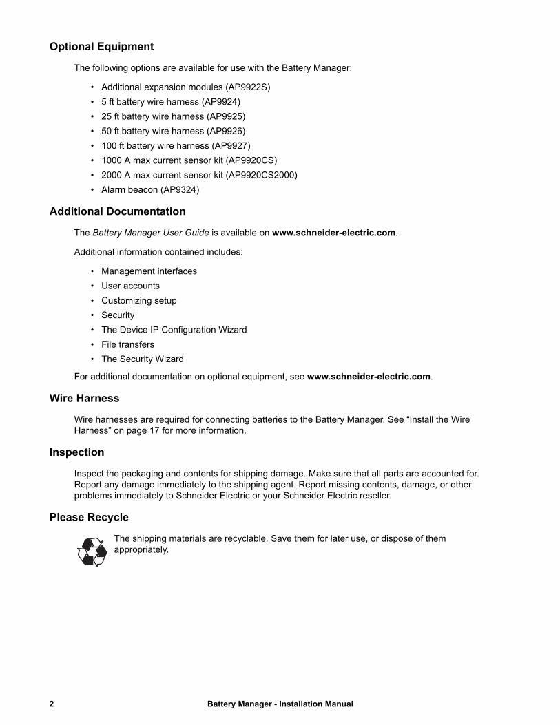
Optional Equipment
The following options are available for use with the Battery Manager:
• Additional expansion modules (AP9922S)
• 5 ft battery wire harness (AP9924)
• 25 ft battery wire harness (AP9925)
• 50 ft battery wire harness (AP9926)
• 100 ft battery wire harness (AP9927)
• 1000 A max current sensor kit (AP9920CS)
• 2000 A max current sensor kit (AP9920CS2000)
• Alarm beacon (AP9324)
Additional Documentation
The Battery Manager User Guide is available on www.schneider-electric.com.
Additional information contained includes:
• Management interfaces
• User accounts
• Customizing setup
• Security
• The Device IP Configuration Wizard
• File transfers
• The Security Wizard
For additional documentation on optional equipment, see www.schneider-electric.com.
Wire Harness
Wire harnesses are required for connecting batteries to the Battery Manager. See “Install the Wire Harness” on page 17 for more information.
Inspection
Inspect the packaging and contents for shipping damage. Make sure that all parts are accounted for. Report any damage immediately to the shipping agent. Report missing contents, damage, or other problems immediately to Schneider Electric or your Schneider Electric reseller.
Please Recycle
The shipping materials are recyclable. Save them for later use, or dispose of them appropriately.
Battery Manager - Installation Manual2

Important Safety InformationRead these instructions carefully and look at the equipment to become familiar with it before trying to install, operate, service or maintain it. The following safety messages may appear throughout this manual or on the equipment to warn of potential hazards or to call attention to information that clarifies or simplifies a procedure.
The addition of this symbol to a “Danger” or “Warning” safety label indicates that an electrical hazard exists which will result in personal injury if the instructions are not followed.
This is the safety alert symbol. It is used to alert you to potential personal injury hazards. Obey all safety messages that follow this symbol to avoid possible injury or death.
Please Note
Electrical equipment should only be installed, operated, serviced, and maintained by qualified personnel. No responsibility is assumed by Schneider Electric for any consequences arising out of the use of this material.
A qualified person is one who has skills and knowledge related to the construction, installation, and operation of electrical equipment and has received safety training to recognize and avoid the hazards involved.
DANGERDANGER indicates an imminently hazardous situation which, if not avoided, will result in death or serious injury.
Failure to follow these instructions will result in death or serious injury.
WARNINGWARNING indicates a potentially hazardous situation which, if not avoided, could result in death or serious injury.
Failure to follow these instructions can result in death, serious injury, or equipment damage.
CAUTIONCAUTION indicates a hazardous situation which, if not avoided, could result in minor or moderate injury.
Failure to follow these instructions can result in injury or equipment damage.
NOTICENOTICE is used to address practices not related to physical injury. The safety alert symbol shall not be used with this type of safety message.
Failure to follow these instructions can result in equipment damage.
3 Battery Manager - Installation Manual

Battery Safety
When Installing the Battery Manager:
• Power off the Battery Manager before connecting the wire harness or before performing any battery maintenance.
• Cover the batteries with an electrical insulating blanket before installing the harnesses.
• Use appropriate tools to avoid damage to the battery terminals or other system components.
• Fasteners should be tightened to the specified torque rating.
• Do not lay tools or metal parts on top of the batteries or near the cable lugs.
• Do not short-circuit the battery terminals; this could cause the batteries to explode.
• Use double-insulated tools.
• Avoid skin contact with battery components, such as electrolyte.
• Wear rubber gloves, rubber boots, and safety goggles.
• Remove watches, rings, and other metal objects.
• For the UPS and switch gear, use lock-out/tag-out safety procedures (which remove access to a device and physically label the device as intentionally out of service) before working on the batteries.
• Use only cables supplied by Schneider Electric unless otherwise indicated.
• Verify presence and location of fire extinguishers or other fire containment methods.
DANGERHAZARD OF ELECTRIC SHOCK
• Battery cabinets contain potentially lethal voltages.
• Batteries are energized even when AC power has been disconnected.
• All electrical equipment must be rated at appropriate voltage for system usage.
• Only qualified personnel trained in battery operation and safety may install the harnesses.
• Keep unauthorized personnel away from the batteries.
Failure to follow these instructions will result in death or serious injury.
DANGERHAZARD OF ELECTRIC SHOCK, EXPLOSION, OR ARC FLASH
Batteries can present a risk of electric shock and high short-circuit current. The following precautions must be observed when working on batteries:
• Remove watches, rings, or other metal objects.
• Use tools with insulated handles.
• Wear protective glasses, gloves and boots.
• Do not lay tools or metal parts on top of batteries.
• Disconnect the charging source prior to connecting or disconnecting battery terminals.
• Determine if the battery is inadvertently grounded. If inadvertently grounded, remove source from ground. Contact with any part of a grounded battery can result in electric shock. The likelihood of such shock can be reduced if such grounds are removed during installation and maintenance (applicable to equipment and remote battery supplies not having a grounded supply circuit).
Failure to follow these instructions will result in death or serious injury.
Battery Manager - Installation Manual4
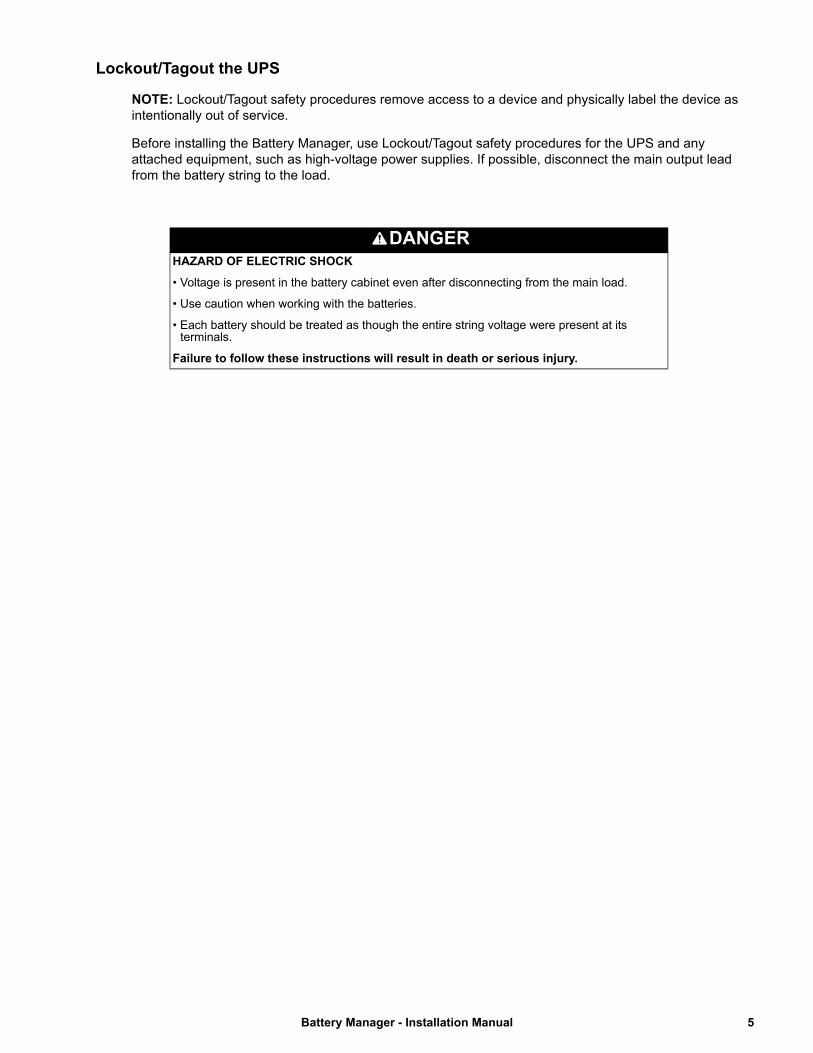
Lockout/Tagout the UPS
NOTE: Lockout/Tagout safety procedures remove access to a device and physically label the device as intentionally out of service.
Before installing the Battery Manager, use Lockout/Tagout safety procedures for the UPS and any attached equipment, such as high-voltage power supplies. If possible, disconnect the main output lead from the battery string to the load.
DANGERHAZARD OF ELECTRIC SHOCK
• Voltage is present in the battery cabinet even after disconnecting from the main load.
• Use caution when working with the batteries.
• Each battery should be treated as though the entire string voltage were present at its terminals.
Failure to follow these instructions will result in death or serious injury.
5 Battery Manager - Installation Manual
System Overview
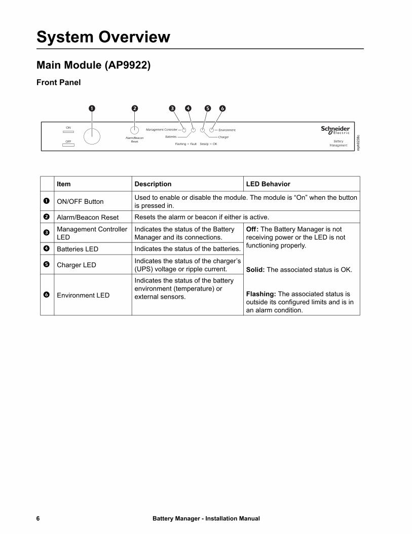
Main Module (AP9922)
Front Panel
Item Description LED Behavior
ON/OFF ButtonUsed to enable or disable the module. The module is “On” when the button is pressed in.
Alarm/Beacon Reset Resets the alarm or beacon if either is active.
Management Controller LED
Indicates the status of the Battery Manager and its connections.
Off : The Battery Manager is not receiving power or the LED is not functioning properly.
Solid: The associated status is OK.
Flashing: The associated status is outside its configured limits and is in an alarm condition.
Batteries LED Indicates the status of the batteries.
Charger LEDIndicates the status of the charger’s (UPS) voltage or ripple current.
Environment LED
Indicates the status of the battery environment (temperature) or external sensors.
mph0238c
Battery Manager - Installation Manual6

Rear Panel
Base-T Port10=Green
100=Orange
mph0237c
Item Description
Ground Ground wire connection.
Battery harness connector (B)
Connects the Battery Manager to the batteries.
Network/Ethernet Connects to the network using a CAT5 (or faster) cable.
Link RX/TX LED
Indicates the status of the network connection.Off: • Cable from Battery Manager to network is disconnected or defective.• Device connecting Battery Manager to network is turned off or not functioning.• The Battery Manager is not receiving power, or needs to be repaired or replaced.• The Battery Manager itself is not operating properly. Contact Customer Support.
Solid Green: connected to a network at 10 Megabits per second (Mbps).Solid Orange: connected to a network at 100 Mbps.Flashing Green: receiving or transmitting data at 10 Mbps.Flashing Orange: receiving or transmitting data at 100 Mbps.
Status LED
Indicates the status of traffic over the network connection.Off: The Battery Manager is not receiving power or the NMC is in a Reboot Sequence. Contact Worldwide Customer Support.Solid Green: The Battery Manager has valid TCP/IP settings.Flashing Green: The Battery Manager does not have valid TCP/IP settings.1
Solid Orange: The Battery Manager’s Network Management Card has detected a hardware problem. Contact Customer Support.Flashing Orange: The Battery Manager is making BOOTP requests.1
Alternating Green & Orange: either starting up or making DHCP requests.1
A-Link Port (2) Reserved for future use.
Expansion Bus Ports (2) Used to cascade one to seven AP9922S modules to a single AP9922 module.
PowerView Port Reserved for future use.
Beacon Connects to optional alarm beacon (AP9324).
Alarm Contact PortUsed to connect external equipment such as an automatic dialer to signal an alarm. This is a summary alarm.
Settings (DIP Switch) Configures the address, termination resistors and serial port mode.
Remote LEDs PortConnects the Battery Manager to the remote alarm reset, or two auxiliary environmental inputs.
Temperature Sensors Port
Connects the temperature sensor assembly (part number 940-0089).
RS-232/485 Port Connects to Modbus or the Command Console to configure the NMC.
Current sensor Ports (A and B)
Connects the Battery Manager to the charge/discharge string current sensors.
Battery harness connector (A)
Connects the Battery Manager to the batteries and to the module power.
Unit # Use this space to write the number of the module for easy identification.
NMC Reset Button Push once to restart network interface, or use to reset the module password.1 To configure the TCP/IP, BOOTP, or DHCP settings, see “TCP/IP” in the Battery Manager User Guide.
7 Battery Manager - Installation Manual
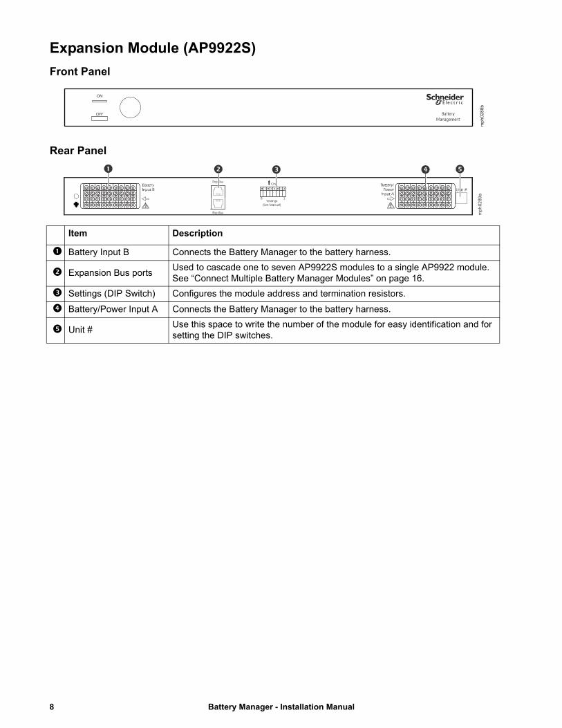
Expansion Module (AP9922S)
Front Panel
mph0288b
Rear Panel
8 1
mp
h02
89a
Item Description
Battery Input B Connects the Battery Manager to the battery harness.
Expansion Bus portsUsed to cascade one to seven AP9922S modules to a single AP9922 module. See “Connect Multiple Battery Manager Modules” on page 16.
Settings (DIP Switch) Configures the module address and termination resistors.
Battery/Power Input A Connects the Battery Manager to the battery harness.
Unit #Use this space to write the number of the module for easy identification and for setting the DIP switches.
Battery Manager - Installation Manual8

InstallationOverview
• If the Battery Manager is installed in an enclosed communications rack, the maximum allowable ambient temperature inside the enclosure is 40°C (104°F). Allow for adequate airflow to ensure that the maximum temperature is not exceeded.
• When installing Battery Manager modules and the included sensors, ensure that the weight of the system is evenly distributed and that the enclosure and flooring can support the total weight.
• Maintain reliable earth grounding of the module.
Install the Battery ManagerFor wall or cabinet-mounting, install the modules using either the rubber feet or the brackets.NOTE: Before beginning installation, identify the installation site, and position the Battery Manager and batteries as desired. Verify the Battery Manager is powered off by checking the ON/OFF button on the front panel is NOT pressed in. Verify that the length of the battery wire harnesses are able to connect the Battery Manager to the batteries.
Rubber Feet Method
To install the Battery Manager module using the rubber feet (provided):
1. Use the alcohol pad (provided) to clean the surface of the bottom of the module.
2. Attach the rubber feet to the bottom of the module, placing one at each corner.
3. Place the module on an even surface, where it will be accessible for connection procedures.
Battery Cabinet Method
NOTE: Procedure applicable to wall or door installation
1. Attach the mounting brackets to the Battery Manager module, using eight pan-head screws (provided).
mp
h00
1a
9 Battery Manager - Installation Manual

2. Mount the module to the door of the battery cabinet or wall:
• If your cabinet has available mounting studs:
• If your cabinet or wall does not have available mounting studs:
a. Align the bolts on the door with the slots on the free flanges of the mounting brackets on the module.
b. Place the module on the studs in the battery cabinet door so that the bolts are aligned with the top of each slot on the flange. Secure the flanges to the bolts with hex nuts.
a. Align the free flanges of the mounting brackets on the Battery Manager module, and mark the locations of the top of each slot on the flange. This is where the bolts or studs will need to be placed.
b. Drill holes in the marked positions, and insert appropriate mounting bolts or studs.
c. Place the module so that the bolts are aligned with the top of each slot on the flange. Secure the flanges to the bolts with hex nuts.
mph
000
7a
Battery Manager - Installation Manual10
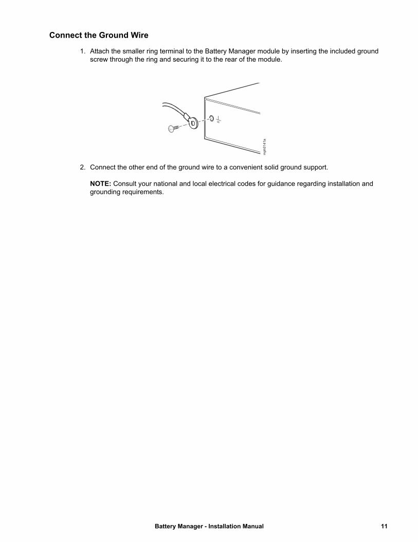
Connect the Ground Wire
1. Attach the smaller ring terminal to the Battery Manager module by inserting the included ground screw through the ring and securing it to the rear of the module.
2. Connect the other end of the ground wire to a convenient solid ground support. NOTE: Consult your national and local electrical codes for guidance regarding installation and grounding requirements.
mph
014
1a
11 Battery Manager - Installation Manual

Configure the DIP SwitchesUse the information below to configure the DIP switches on the rear panel of the Battery Manager module. The switches are recessed inside the space marked Settings. Use a small tool such as a pocket screwdriver to push each switch into the correct position.
NOTE: When viewed from the rear of the module, 8 is the left-most switch, and the numbers decrease to 1 on the right side.
Function DIP Switch Number
8 7 6 5 4 3 2 1
System Address # 1† (AP9922 Main module) – – – – – OFF OFF OFF
System Address # 2 (AP9922S expansion module) – – – – – ON OFF OFF
System Address # 3 (AP9922S expansion module) – – – – – OFF ON OFF
System Address # 4 (AP9922S expansion module) – – – – – ON ON OFF
System Address # 5 (AP9922S expansion module) – – – – – OFF OFF ON
System Address # 6 (AP9922S expansion module) – – – – – ON OFF ON
System Address # 7 (AP9922S expansion module) – – – – – OFF ON ON
System Address # 8 (AP9922S expansion module) – – – – – ON ON ON
Modbus Terminator Out† – – OFF – – – – –
Modbus Terminator In – – ON – – – – –
RS-232 Communications Console Selected † – OFF – – – – – –
RS-485 Modbus Communications Console Selected – ON – – – – – –
Expansion Bus Terminator Out † OFF – – – – – – –
Expansion Bus Terminator In ON – – – – – – –
† Factory Default Setting
Battery Manager - Installation Manual12
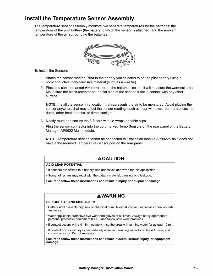
Install the Temperature Sensor AssemblyThe temperature sensor assembly monitors two separate temperatures for the batteries: the temperature of the pilot battery (the battery to which the sensor is attached) and the ambient temperature of the air surrounding the batteries.
To Install the Sensors:
1. Attach the sensor marked Pilot to the battery you selected to be the pilot battery using a non-conductive, non-corrosive material (such as a wire tie).
2. Place the sensor marked Ambient around the batteries, so that it will measure the warmest area. Make sure the black receptor on the flat side of the sensor is not in contact with any other surface.NOTE: Install the sensor in a location that represents the air to be monitored. Avoid placing the sensor anywhere that may affect the sensor reading, such as near windows, room entrances, air ducts, other heat sources, or direct sunlight.
. 3. Neatly route and secure the 8-ft cord with tie-wraps or cable clips.
4. Plug the sensor connector into the port marked Temp Sensors on the rear panel of the Battery Manager AP9922 Main module.NOTE: Temperature sensor cannot be connected to Expansion module AP9922S as it does not have a the required Temperature Sensor port on the rear panel.
CAUTIONACID LEAK POTENTIAL
• If sensors are affixed to a battery, use adhesives approved for this application.
• Some adhesives may react with the battery material, causing acid leakage.
Failure to follow these instructions can result in injury or equipment damage.
WARNINGSERIOUS EYE AND SKIN INJURY
• Battery acid presents high risk of chemical burn. Avoid all contact, especially open wounds and eyes.
• Wear applicable protective eye wear and gloves at all times. Always apply appropriate personal protective equipment (PPE), and follow safe work practices.
• If contact occurs with skin, immediately rinse the area with running water for at least 15 min.
• If contact occurs with eyes, immediately rinse with running water for at least 15 min, and consult a doctor. Do not rub eyes.
Failure to follow these instructions can result in death, serious injury, or equipment damage.
gen
0115
a
13 Battery Manager - Installation Manual
Install the Current SensorOne Current Sensor for the Battery Manager is recommended per string of batteries.
The AP9922/AP9922S Battery Manager Kit does not include a Current Sensor. For purchasing information, contact your Schneider Electric reseller or visit www.schneider-electric.com.
A maximum of two Current Sensors can be connected per Battery Manager Main module AP9922. Depending on the system configuration, there are two Current Sensor options available:
• AP9920CS: I ≤ 1000 A
• AP9920CS2000: 1000 A < I ≤ 2000 A
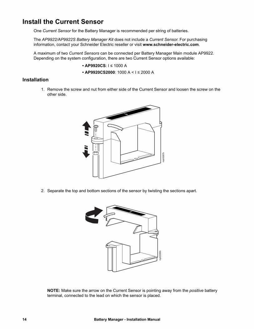
Installation
1. Remove the screw and nut from either side of the Current Sensor and loosen the screw on the other side.
2. Separate the top and bottom sections of the sensor by twisting the sections apart.
NOTE: Make sure the arrow on the Current Sensor is pointing away from the positive battery terminal, connected to the lead on which the sensor is placed.
mph0267b
mph0266b
Battery Manager - Installation Manual14

3. Place the separated parts of the sensor around the main output battery lead on any battery. Secure the sensor in place using the screw and nut removed in Step 1. Tighten the remaining screw.
4. Plug the current sensor connector into the connector port called Current Probes - Probe A on the rear of the Battery Manager Main module AP9922.NOTE: Expansion module AP9922S cannot be connected to a current sensor. It does not have a Current Probes port on the rear panel.If a second string of batteries is connected to the Battery Manager AP9922 Main module, a second current sensor must be installed on that string of batteries and must be connected to the port labeled Current Probes - Probe B on the rear of the module.
mph0264b
UPS / Charger / Load
15 Battery Manager - Installation Manual

Connect Multiple Battery Manager ModulesUp to 7 Battery Manager Expansion modules, AP9922S, can be connected to one Battery Manager Main module, AP9922, when all modules are connected to the same UPS. The modules will use a single network connection. The modules must be connected serially and the DIP switches of each module must be set to identify the address of the module.
1. Plug a serial cable (0466-25) into the rear of the first Battery Manager Main module AP9922 in either expansion bus port marked Exp Bus.
2. Connect the other end of the serial cable to an expansion bus port marked Exp Bus on the rear of the second Battery Manager Expansion module AP9922S.
– If you connected the serial cable to the bottom expansion bus port of the first Battery Manager module AP9922, connect the other end of the serial cable to the top expansion bus port of the second Battery Manager Expansion module AP9922S (as shown in the diagram below).
– If you connected the serial cable to the top expansion bus port of the first Battery Manager Main module AP9922, connect the other end of the serial cable to the bottom expansion bus port of the second Battery Manager Expansion module AP9922S.
3. Continue to connect the Battery Manager modules as described in the previous steps until they are all connected. The third Battery Manager module AP9922S will connect with the second Battery Manager AP9922S, Etc.
4. Set the address for each Battery Manager module. The first Battery Manager (Main module) must be addressed as #1 (all DIP switches OFF) for the configuration to work, and each additional Battery Manager Expansion module AP9922S should be sequentially and consecutively addressed. Assign a number to each Battery Manager module and write the number in the space marked Unit # on the back of each module. See “Configure the DIP Switches” on page 12.
5. For the first and last Battery Manager modules on the network, set DIP switch #8 to ON to enable the terminator.
The following cascaded configuration shows three Battery Manager modules serially connected. Your setup may vary from the one shown.
Main module: In this cascading example, this is unit #1 (AP9922). The second Expansion Bus port is not used.
Expansion module: In this cascading example, this is unit #2 (AP9922S).
Expansion module: In this cascading example, this is unit #3 (AP9922S). The second Expansion Bus port is not used.
Serial cable to connect each Battery Manager module.
RemoteLEDs
Base-T Port
10=Green100=Orange
8 1
8 1
8 1
mph0260b
Battery Manager - Installation Manual16

Install the Wire HarnessThe Wire Harness for the Battery Manager connects the UPS batteries to the Battery Manager. It is not included with the AP9922/AP9922S Battery Manager. For purchasing information, contact your Schneider Electric reseller or visit www.schneider-electric.com.
Each Battery Manager - Main Module AP9922 or Expansion Module AP9922S - can receive up to 2 wire harnesses. Each Wire Harness connects up to 32 batteries to the Battery Manager.
The first Wire Harness connects to the port labeled “Battery/Power Input A” on the back of the Battery Manager. This Wire Harness will be relabeled Wire Harness A, and will:
• Connect the first 32 batteries on the string - batteries #1 to #32 - to the Battery Manager
• Connect the Battery Manager to its power source: the UPS charger.
The second Wire Harness connects to the port labeled “Battery Input B” on the back of the Battery Manager.This Wire Harness will be relabeled Wire Harness B, and will:
• Connect the next 32 batteries on the string - batteries #33 to #64 - to the Battery Manager.
DANGERHAZARD OF ELECTRIC SHOCK
• The Battery Manager must be powered off before connecting the wire harness or before performing any battery maintenance.
• Installation of wire harness must only be performed by qualified personnel knowledgeable of batteries and the required precautions. Keep unqualified personnel away from batteries.
Failure to follow these instructions will result in death or serious injury.
NOTICERISK OF EQUIPMENT DAMAGE
The Battery Manager must be powered off before connecting the wire harness or before performing any battery maintenance.
Failure to follow these instructions can result in equipment damage.
DANGERHAZARD OF ELECTRIC SHOCK
• Battery cabinets contain potentially lethal voltages.
• Batteries are energized even when AC power has been disconnected.
• All electrical equipment must be rated at appropriate voltage for system usage.
• Only qualified personnel trained in battery operation and safety may install the harnesses.
• Keep unauthorized personnel away from the batteries.
Failure to follow these instructions will result in death or serious injury.
17 Battery Manager - Installation Manual

Depending on the length of the cables, there are 4 Wire Harness options:
• AP9924 - 5 ft length cable
• AP9925 - 25 ft length cable
• AP9926 - 50 ft length cable
• AP9927 - 100 ft length cable
NOTE: For more information see the Wire Harness for the Battery Manager Installation Manual, available at www.schneider-electric.com.
Battery Manager - Installation Manual18

Quick Configuration (Main module AP9922)Overview
NOTE: Disregard the procedures in this section if the Battery Manager is installed to the StuxureWare Data Center Expert private LAN only. In this case, the Battery Manager will automatically get a DHCP address assigned. In any other case, follow the procedures below. That includes the case where the Battery Manager is installed to the StruxureWare Data Center Expert public LAN.
NOTE: The Battery Manager Expansion module AP9922S does not require IP settings. It is connected to the network via the Battery Manager Main module AP9922. Only the Main module AP9922 requires an IP address to be set up.
The following TCP/IP settings must be configured before the Battery Manager Main module, AP9922can operate on the network:
• IP address of the Main module AP9922
• Subnet mask
• Default gateway
NOTE: If a default gateway is unavailable, use the IP address of a computer that is located on the same subnet as the Battery Manager module. The module uses the default gateway to test the network when traffic is very light.
Do not use the loopback address (127.0.0.1) as the default gateway address for the Network Management Card. It disables the card and requires you to reset TCP/IP settings to their defaults using a local serial login.
• See “Watchdog Features” in the Battery Manager User Guide for more information about the watchdog role of the default gateway.
TCP/IP Configuration Introduction
The TCP/IP settings for the Battery Manager Main module AP9922 can be configured:
Local Access
• “Serial Port / Local Access to the Command Console” on page 20.
Remote Access
• “Remote TCP/IP Configuration Using BOOTP & DHCP Server” on page 21.
• “Remote TCP/IP Configuration Using Device IP Configuration Wizard” on page 22.
• “Remote TCP/IP Configuration Using ARP Command” on page 23.
19 Battery Manager - Installation Manual
Local TCP/IP Configuration
Serial Port / Local Access to the Command Console
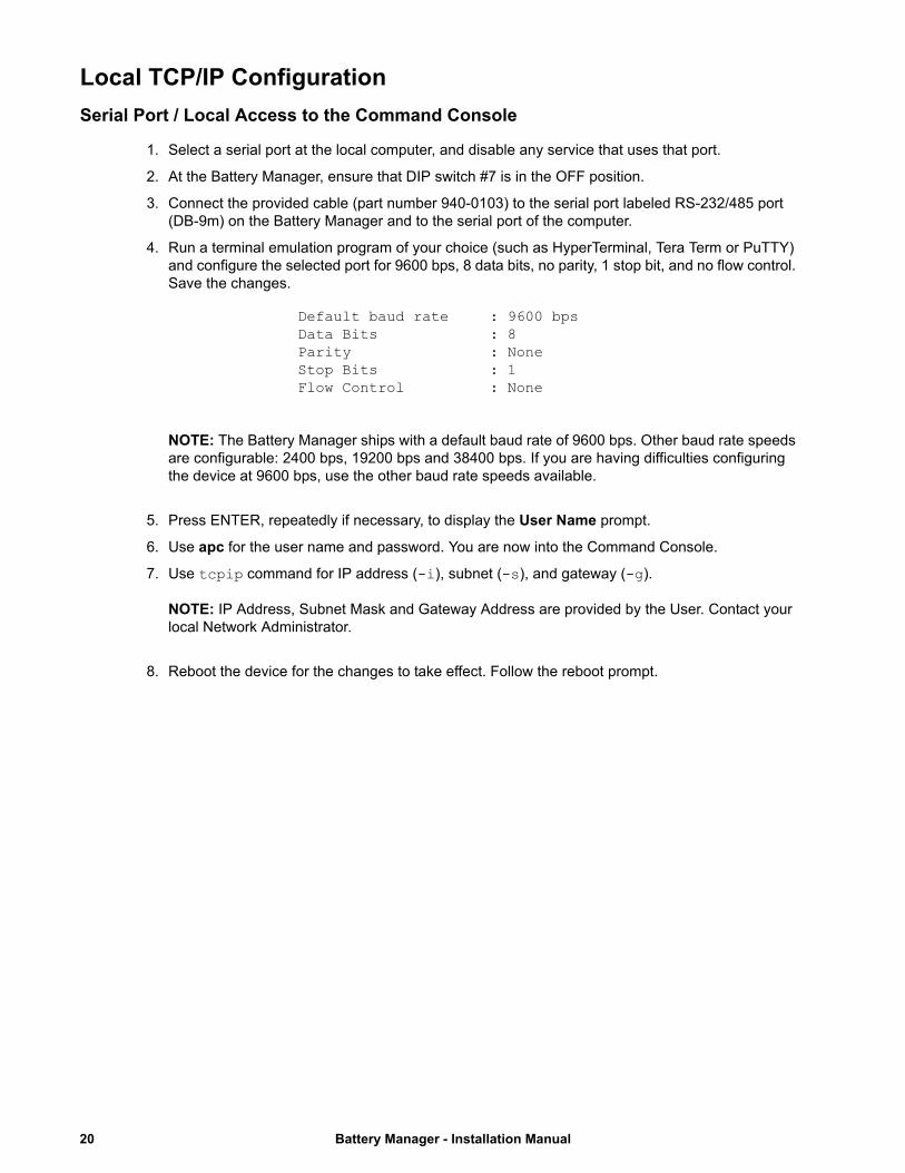
1. Select a serial port at the local computer, and disable any service that uses that port.
2. At the Battery Manager, ensure that DIP switch #7 is in the OFF position.
3. Connect the provided cable (part number 940-0103) to the serial port labeled RS-232/485 port (DB-9m) on the Battery Manager and to the serial port of the computer.
4. Run a terminal emulation program of your choice (such as HyperTerminal, Tera Term or PuTTY) and configure the selected port for 9600 bps, 8 data bits, no parity, 1 stop bit, and no flow control. Save the changes.
NOTE: The Battery Manager ships with a default baud rate of 9600 bps. Other baud rate speeds are configurable: 2400 bps, 19200 bps and 38400 bps. If you are having difficulties configuring the device at 9600 bps, use the other baud rate speeds available.
5. Press ENTER, repeatedly if necessary, to display the User Name prompt.
6. Use apc for the user name and password. You are now into the Command Console.
7. Use tcpip command for IP address (-i), subnet (-s), and gateway (-g). NOTE: IP Address, Subnet Mask and Gateway Address are provided by the User. Contact your local Network Administrator.
8. Reboot the device for the changes to take effect. Follow the reboot prompt.
Default baud rate : 9600 bpsData Bits : 8Parity : NoneStop Bits : 1Flow Control : None
Battery Manager - Installation Manual20
Remote TCP/IP Configuration
Remote TCP/IP Configuration Using BOOTP & DHCP Server
The default TCP/IP configuration setting, BOOTP & DHCP, assumes that a properly configured BOOTP or DHCP server is available to provide TCP/IP settings. The unit first attempts to discover a properly configured BOOTP server, and then a DHCP server. It repeats this pattern until it discovers a BOOTP or DHCP server.
If neither is available, see “Remote TCP/IP Configuration Using Device IP Configuration Wizard” on page 22, “Serial Port / Local Access to the Command Console” on page 20, or “Remote TCP/IP Configuration Using ARP Command” on page 23 to configure the required TCP/IP settings.
BOOTP. For the Battery Manager Main module AP9922 to use a BOOTP server to configure its TCP/IP settings, it must find a properly configured RFC951-compliant BOOTP server.
In the BOOTPTAB file of the BOOTP server, enter the unit’s MAC address, IP address, subnet mask, and default gateway, and, optionally, a bootup file name.
When the unit reboots, the BOOTP server provides it with the TCP/IP settings.
DHCP. You can use an RFC2131/RFC2132-compliant DHCP server to configure the TCP/IP settings for the Battery Manager Main module AP9922.
This section briefly summarizes the unit communication with a DHCP server. For more detail about how a DHCP server is used to configure the network settings for a Main module, see “DHCP Configuration Settings” in the Battery Manager User Guide, available at www.schneider-electric.com.
1. A Battery Manager Main module AP9922 sends out a DHCP request using the following to identify itself:
– A Vendor Class Identifier (APC by default)
– A Client Identifier (by default, the unit’s MAC address value)
– A User Class Identifier (by default, the identification of the unit’s application firmware)
2. A properly configured DHCP server responds with a DHCP offer that includes the settings needed for network communication.
21 Battery Manager - Installation Manual

Remote TCP/IP Configuration Using Device IP Configuration Wizard
NOTE: More secure IPv6 IP addresses cannot be configured via the Device IP Configuration Wizard. To configure IPv6 IP addresses, follow the instructions “Remote TCP/IP Configuration Using BOOTP & DHCP Server” on page 21.
The Device IP Configuration Wizard can be used to discover an unconfigured Battery Manager Main module AP9922 on a network, and configure its basic TCP/IP settings.
To configure one or more Main modules by exporting configuration settings from a configured Main module, see “How to Export Configuration Settings” in the Battery Manager User Guide.NOTE: Software firewalls may need to be temporarily disabled for the Device IP Configuration Wizard to properly function.
System requirements. The Device IP Configuration Wizard runs on Microsoft ® Windows® 2000, Windows Server ® 2003, Windows Server® 2012, and on 32- and 64-bit versions of Windows XP, Windows Vista, Windows 2008, Windows 7, Windows 8, and Windows 10 operating systems.
The Device IP Configuration Wizard supports cards that have firmware version 3.0.x or higher and is for IPv4 only. To configure the device with IPv6, one of the other remote configuration options must be used.
Installation. To install the Device IP Configuration Wizard from a downloaded executable file:
1. Go to www.schneider-electric.com.
2. Download the Device IP Configuration Wizard.
3. Run the downloaded executable file, and follow on-screen instructions. When installed, the Device IP Configuration Wizard is available through the Windows Start menu options.
4. Look for the device MAC address on the product nameplate (e.g.: 00-C0-B7-xx-xx-xx).
5. Go to Tab titled Find and setup device off network.
6. Click Start Search button.
7. The MAC Address of the Battery Manager will show up. Select it.
8. Set up the IP Address, Subnet Mask and Gateway Address. Click Apply the changes.NOTE: IP Address, Subnet Mask and Gateway Address are provided by the User. Contact your local Network Administrator.
Battery Manager - Installation Manual22
Remote TCP/IP Configuration Using ARP Command
NOTE: The following instructions are ONLY valid if the Battery Manager is on the same subnet as the User.
From any computer on the same subnet as the Battery Manager Main module AP9922, you can use ARP and Ping to assign an IP address to a Battery Manager Main module, and then use Telnet to access the Main module's Control Console and configure the other TCP/IP settings.
1. Use the Battery Manager Main module's MAC address in the ARP command to define the IP address. For example, to define 156.205.14.141 as the IP address of a unit with MAC address 00 c0 b7 63 9f 67, use one of the following commands:
– Windows command format:
arp -s 156.205.14.141 00-c0-b7-63-9f-67
– LINUX command format:
arp -s 156.205.14.141 00:c0:b7:63:9f:67
NOTE: IP Address, Subnet Mask and Gateway Address are provided by the User. Contact your local Network Administrator.
2. Use Ping with a size of 113 bytes to assign the IP address defined by the ARP command. For the IP address defined in step , use one of the following commands:
– Windows command format:
ping 156.205.14.141 -l 113
– LINUX command format:
ping 156.205.14.141 -s 113
3. Use Telnet to access the unit at its newly assigned IP address. For example:
telnet 156.205.14.141
4. Use apc for both user name and password. You are now in the Control Console.
5. Use tcpip command for IP address (-i), subnet (-s), and gateway (-g). NOTE: IP Address, Subnet Mask and Gateway Address are provided by the User. Contact your local Network Administrator.
6. Reboot the device for the changes to take effect. Follow the reboot prompt.
23 Battery Manager - Installation Manual
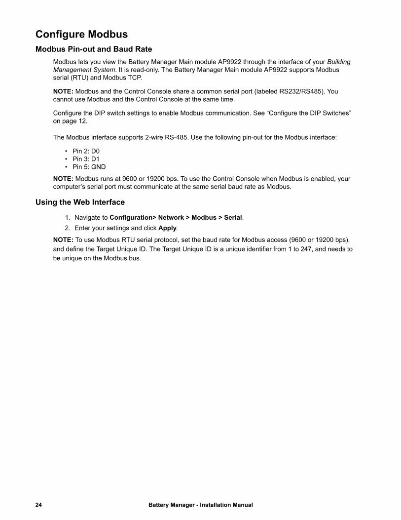
Configure ModbusModbus Pin-out and Baud Rate
Modbus lets you view the Battery Manager Main module AP9922 through the interface of your Building Management System. It is read-only. The Battery Manager Main module AP9922 supports Modbus serial (RTU) and Modbus TCP.
NOTE: Modbus and the Control Console share a common serial port (labeled RS232/RS485). You cannot use Modbus and the Control Console at the same time.
Configure the DIP switch settings to enable Modbus communication. See “Configure the DIP Switches” on page 12.
The Modbus interface supports 2-wire RS-485. Use the following pin-out for the Modbus interface:
• Pin 2: D0• Pin 3: D1• Pin 5: GND
NOTE: Modbus runs at 9600 or 19200 bps. To use the Control Console when Modbus is enabled, your computer’s serial port must communicate at the same serial baud rate as Modbus.
Using the Web Interface
1. Navigate to Configuration> Network > Modbus > Serial.
2. Enter your settings and click Apply.
NOTE: To use Modbus RTU serial protocol, set the baud rate for Modbus access (9600 or 19200 bps),
and define the Target Unique ID. The Target Unique ID is a unique identifier from 1 to 247, and needs to
be unique on the Modbus bus.
Battery Manager - Installation Manual24

Access a Configured Battery Manager
Overview
After the Battery Manager Main module AP9922 is running on your network, you can use the interfaces summarized here: Web interface, Telnet and SSH, SNMP, FTP and SCP.
See the Battery Manager User Guide, available at www.schneider-electric.com, for additional information regarding:
– Using any of the interfaces
– Configuring system parameters through either the Web Interface or Control Console
For the system configuration parameters, you must configure Battery Type, Number of Strings, Number of Cells per Battery, and Number of Batteries per String.
Change other system configuration parameters only if you have consulted with a Schneider Electric Customer Support or Customer Service representative.
Web Interface
Use Microsoft® Internet Explorer (IE) 5.5 or higher (on Windows operating systems only), Firefox, version 1.x, by Mozilla Corporation (on all operating systems), or Netscape® 7.x or higher (on all operating systems) to access the Web interface of the Battery Manager Main module. Other commonly available browsers may work but have not been fully tested by Schneider Electric.
You can use either of the following protocols when using the web interface:
• The HTTP protocol (enabled by default), which provides authentication by user name and password but no encryption.
• The HTTPS protocol, which provides extra security through Secure Sockets Layer (SSL), encrypts user names, passwords, and data being transmitted, and authenticates the Battery Manager by means of digital certificates.
To access the Web interface and configure the security of your device on the network:
1. Address the Battery Manager Main module AP9922 by its IP address (or its DNS name, if a DNS name is configured).
2. Enter the user name and password (by default, apc and apc for an Administrator).
3. Navigate to Configuration > Network > Web > Access, to enable or disable the HTTP or HTTPS protocols.
For more information on selecting and configuring network security, see the Security Handbook available from the Schneider Electric web site, www.schneider-electric.com.
25 Battery Manager - Installation Manual
Telnet or Secure SHell (SSH)
The Control Console can be accessed through Telnet or Secure SHell (SSH), depending on which is enabled. By default, Telnet is enabled. Enabling SSH automatically disables Telnet.
Telnet for basic access. Telnet provides the basic security of authentication by user name and password, but not the high-security benefits of encryption. To use Telnet to access the Battery Manager Main module AP9922 Control Console from any computer on the same subnet:
1. At a command prompt, use the following command line, and press ENTER:
telnet address
As address, use the Battery Manager Main module's IP address or DNS name (if configured).
2. Enter the user name and password (by default, apc and apc for an Administrator, or device and apc for a Device User).
SSH for high-security access. If you use the high security of SSL for the Web interface, use Secure SHell (SSH) for access to the Control Console. SSH encrypts user names, passwords, and transmitted data.
The interface, user accounts, and user access rights are the same whether you access the Control Console through SSH or Telnet, but to use SSH, you must first configure SSH and have an SSH client program installed on your computer.
See the Battery Manager User Guide for more information on configuring and using SSH.
Simple Network Management Protocol (SNMP)
SNMPv1 only. After you add the PowerNet® MIB to a standard SNMP MIB browser, you can use that browser to access the Battery Manager Main module AP9922. All user names, passwords, and community names for SNMP are transferred over the network as plain text. The default read community name is public; the default read/write community name is private.
SNMPv3 only. For SNMP GETs, SETs, and trap receivers, SNMPv3 uses a system of user profiles to identify users. An SNMPv3 user must have a user profile assigned in the MIB software program to perform GETs and SETs, browse the MIB, and receive traps.
NOTE: To use SNMPv3, you must have a MIB program that supports SNMPv3. The Battery Manager Main module AP9922 supports only MD5 authentication and DES encryption.
To use StruxureWare Data Center Expert to manage the Battery Manager Main module on the public network of a StruxureWare system, you must have SNMPv1 enabled in the unit interface.
Through the web interface (with Administrator access), enable or disable SNMP access via:
• SNMPv1: Configuration > Network > SNMPv1 > Access
• SNMPv3: Configuration > Network > SNMPv3 > Access
Battery Manager - Installation Manual26

FTP and SCP
You can use FTP (enabled by default) or SCP to transfer downloaded firmware to a unit, or to access a copy of a unit’s event or data logs.
To use StruxureWare Data Center Expert to manage the Battery Manager Main module AP9922, you must have FTP Server enabled in the unit interface.
Through the web interface (with Administrator access), enable or disable FTP Server access via:
• Configuration > Network > FTP Server
NOTE: In the Battery Manager User Guide, see the following sections:
• To transfer firmware, see “File Transfers.”
• To retrieve a copy of the event or data log, see “How to use FTP or SCP to retrieve log files.”
Upgrade FirmwareFor a complete description on how to download and perform a firmware upgrade for your Battery Manager, visit www.schneider-electric.com and download the Battery Manager User Guide.
27 Battery Manager - Installation Manual
CalibrationCalibration of the Battery Manager
The Battery Manager main module AP9922, and expansion module AP9922S must be calibrated during first installation of the system and when a full string battery replacement is performed.
Please contact your local Schneider Electric Service Representative to set up a visit for the calibration of the equipment.
Battery Manager - Installation Manual28
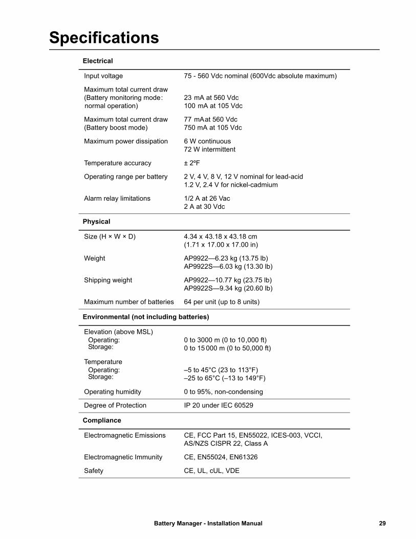
SpecificationsElectrical
Input voltage 75 - 560 Vdc nominal (600Vdc absolute maximum)
Maximum total current draw(Battery monitoring mode : normal operation)
23 mA at 560 Vdc100 mA at 105 Vdc
Maximum total current draw(Battery boost mode)
77 mA at 560 Vdc750 mA at 105 Vdc
Maximum power dissipation 6 W continuous72 W intermittent
Temperature accuracy ± 2ºF
Operating range per battery 2 V, 4 V, 8 V, 12 V nominal for lead-acid1.2 V, 2.4 V for nickel-cadmium
Alarm relay limitations 1/2 A at 26 Vac2 A at 30 Vdc
Physical
Size (H × W × D) 4.34 x 43.18 x 43.18 cm (1.71 x 17.00 x 17.00 in)
Weight AP9922—6.23 kg (13.75 lb)AP9922S—6.03 kg (13.30 lb)
Shipping weight AP9922—10.77 kg (23.75 lb)AP9922S—9.34 kg (20.60 lb)
Maximum number of batteries 64 per unit (up to 8 units)
Environmental (not including batteries)
Elevation (above MSL)Operating:Storage:
0 to 3000 m (0 to 10 ,000 ft)0 to 15 000 m (0 to 50,000 ft)
TemperatureOperating:Storage:
–5 to 45°C (23 to 113°F) –25 to 65°C (–13 to 149°F)
Operating humidity 0 to 95%, non-condensing
Degree of Protection IP 20 under IEC 60529
Compliance
Electromagnetic Emissions CE, FCC Part 15, EN55022, ICES-003, VCCI, AS/NZS CISPR 22, Class A
Electromagnetic Immunity CE, EN55024, EN61326
Safety CE, UL, cUL, VDE
29 Battery Manager - Installation Manual


Worldwide Customer SupportCustomer support for this or any other product is available at www.schneider-electric.com.
12/2015990-1649F-001
© 2015 Schneider Electric. All Rights Reserved. All other trademarks are the property of their respective owners.