Battery Installation Ni-Cad Instructions_C135698
26
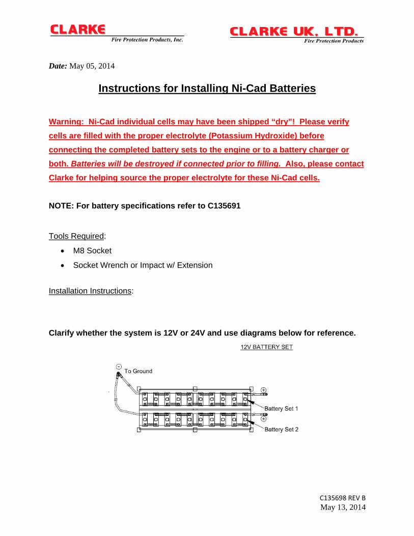
C135698 REV B May 13, 2014 Date: May 05, 2014 Instructions for Installing Ni-Cad Batteries Warning: Ni-Cad individual cells may have been shipped “dry”! Please verify cells are filled with the proper electrolyte (Potassium Hydroxide) before connecting the completed battery sets to the engine or to a battery charger or both. Batteries will be destroyed if connected prior to filling. Also, please contact Clarke for helping source the proper electrolyte for these Ni-Cad cells. NOTE: For battery specifications refer to C135691 Tools Required : M8 Socket Socket Wrench or Impact w/ Extension Installation Instructions : Clarify whether the system is 12V or 24V and use diagrams below for reference.
-
Upload
ricardo-barros -
Category
Documents
-
view
26 -
download
2
description
Battery installation NFPA
Transcript of Battery Installation Ni-Cad Instructions_C135698
C135698 REV B
May 13, 2014
Date: May 05, 2014
Instructions for Installing Ni-Cad Batteries
Warning: Ni-Cad individual cells may have been shipped “dry”! Please verify
cells are filled with the proper electrolyte (Potassium Hydroxide) before
connecting the completed battery sets to the engine or to a battery charger or
both. Batteries will be destroyed if connected prior to filling. Also, please contact
Clarke for helping source the proper electrolyte for these Ni-Cad cells.
NOTE: For battery specifications refer to C135691
Tools Required:
M8 Socket
Socket Wrench or Impact w/ Extension
Installation Instructions:
Clarify whether the system is 12V or 24V and use diagrams below for reference.
spatel
Typewritten Text
spatel
Typewritten Text
(1 of 26)
C135698 REV B
May 13, 2014
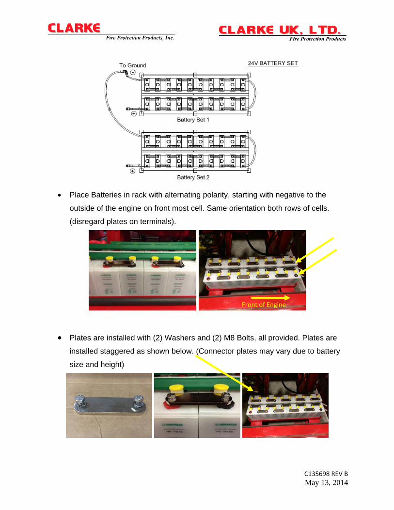
Place Batteries in rack with alternating polarity, starting with negative to the
outside of the engine on front most cell. Same orientation both rows of cells.
(disregard plates on terminals).
Plates are installed with (2) Washers and (2) M8 Bolts, all provided. Plates are
installed staggered as shown below. (Connector plates may vary due to battery
size and height)
Front of Engine
spatel
Typewritten Text
(2 of 26)
C135698 REV B
May 13, 2014
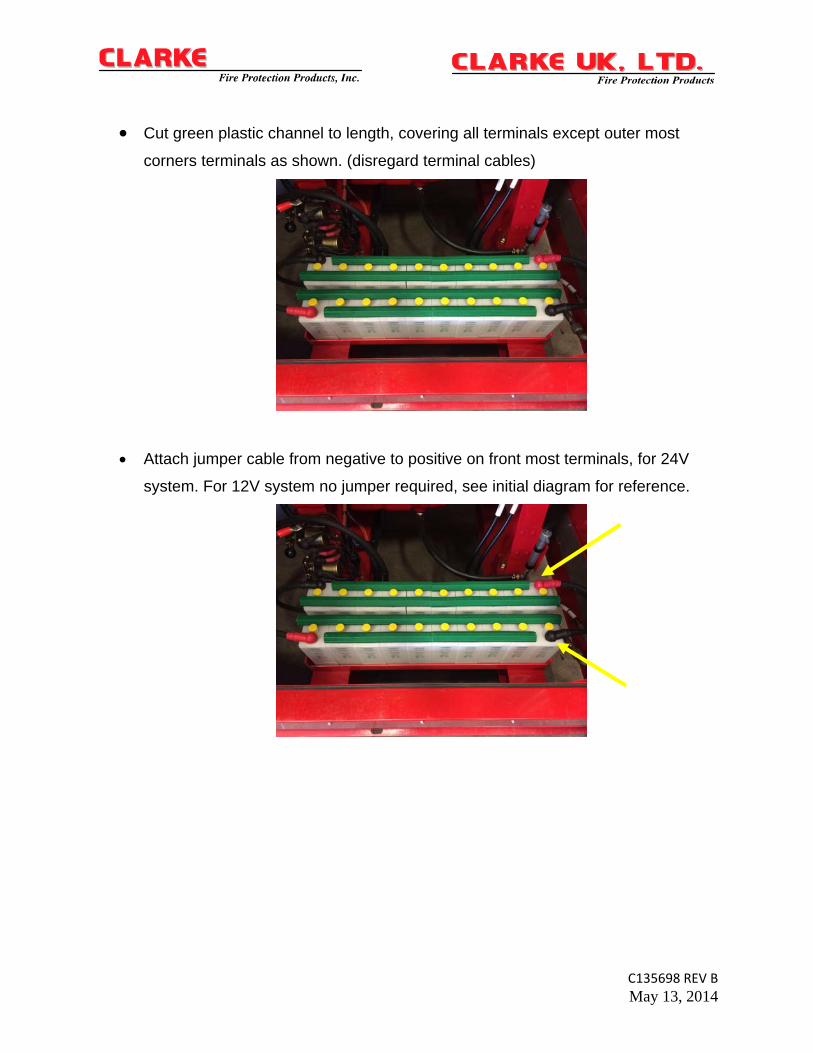
Cut green plastic channel to length, covering all terminals except outer most
corners terminals as shown. (disregard terminal cables)
Attach jumper cable from negative to positive on front most terminals, for 24V
system. For 12V system no jumper required, see initial diagram for reference.
spatel
Typewritten Text
spatel
Typewritten Text
(3 of 26)
C135698 REV B
May 13, 2014
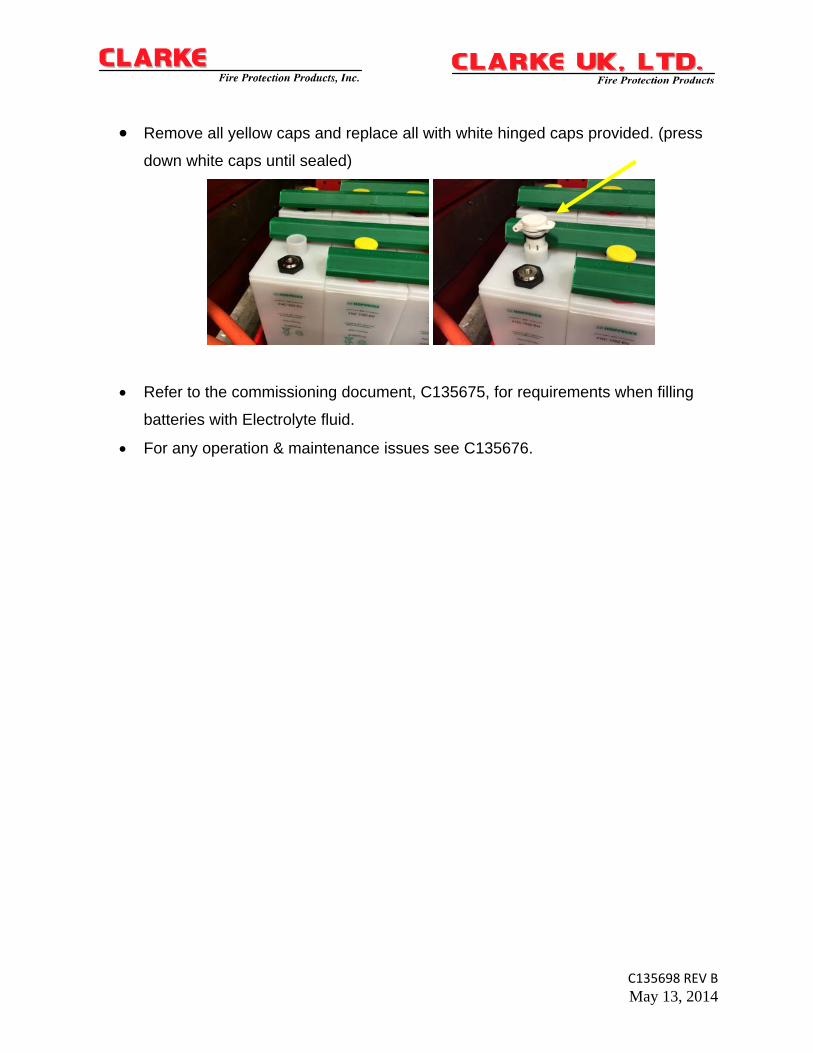
Remove all yellow caps and replace all with white hinged caps provided. (press
down white caps until sealed)
Refer to the commissioning document, C135675, for requirements when filling
batteries with Electrolyte fluid.
For any operation & maintenance issues see C135676.
spatel
Typewritten Text
(4 of 26)
spatel
Typewritten Text
HOPPECKEAssembly and Installation Instructions
Stationary Nickel-Cadmium Batterieswith FNC cells
(Batteries / Racks / Cabinet)
It is assumed that only qualified person-nel are engaged in assembly and instal-lation of the components provided.Qualified personnel are persons who,on the strength of their training, expe-rience and instruction, together withtheir knowledge of the relevant stan-dards, provisions, accident preventionregulations and operating conditions,have been authorised by those responsi-ble for the safety of the components / in-stallation, to carry out the relevant ne-cessary work, with the ability to recogni-se and avoid possible hazards.Amongst other things, knowledge ofFirst Aid and of local rescue equipmentare also necessary.
Failure to observe the instruc-tions on use, repair with non-ori-ginal parts, unauthorised inter-vention, or use of additives tothe electrolyte shall render thewarranty void.
Safety instructions
The following safety measures relate tothe handling of batteries and are to beobserved in connection with all opera-ting instructions contained in these in-structions.
Observe assembly and installa-tion instructions and display visi-bly at point of installation.Work on batteries only after in-struction by qualified staff. Theoperating instructions must al-ways be accessible to personnelresponsible for dealing with bat-teries.
Wear eye protection and pro-tective clothing when workingwith batteries.Observe accident prevention re-gulations.
No smoking. No open flame,embers or sparks in the vicinityof the battery, to avoid risk ofexplosion and fire.
Explosion and fire risk, avoidshort-circuits.Warning! Metal parts of thebattery cells are always live.Never place objects or tools onthe battery. Ensure adequateventilation of the battery room,so that explosive gasesproduced during charging aredrawn off (see DIN EN50272-2).
Have eye rinsing bottle ready athand. If electrolyte splashes intothe eyes or onto the skin, rinsewith plenty of clear water andseek immediate medical advice. Clothing contaminated withelectrolyte is to be washed tho-roughly.
Electrolyte is highly corrosive. Innormal operation there is nopossibility of contact with theelectrolyte. Electrolyte is relea-sed only if the cell housing isdestroyed.
Do not tilt the batteryUse only approved lifting andconveying equipment e.g. liftinggear. Lifting hooks must not cau-se damage to cells, connectorsor connection cables.
Dangerous electrical voltage.Use only suitable tools andmeasuring instruments.
First Aid measures
Electrolyte in contact with the eyes:
• Rinse immediately with plenty of waterfor at least 10 minutes.
• If available, rinse the eyes with boricacid solution.
• Immediately visit the eye clinic/eyecasualty department.
Electrolyte in contact with the skin:
• Immediately remove clothing contami-nated by electrolyte, and wash affec-ted areas of skin with plenty of water.Visit doctor if any problems occur.
• Skin which has been in contact withelectrolyte has a soapy consistency.Continue rinsing with water until nor-mal skin condition has been restored.
If electrolyte is swallowed:
• Rinse out mouth immediately withplenty of water, and repeatedly drinklarge amounts of water.
• Do not induce vomiting. Call emergen-cy medical service immediately.
Protection against dangerousbody contact currents
In stationary battery installations, measu-res must be taken to guard against di-rect and indirect contact. For battery in-stallations this protection can take theform of obstacles or distance. Battery in-stallations with a rated voltage of morethan 120 V must be accommodated inenclosed, electrical operating areas.Doors of battery rooms and cubiclescount as obstacles when they are identi-fied by the following warning plates (fit-ted externally):
• Warning plate “Dangerous Voltage”,if the battery voltage exceeds 60 V(see ISO 3864)
spatel
Typewritten Text
C135674 REV A 04APR14
spatel
Typewritten Text
spatel
Typewritten Text
spatel
Typewritten Text
(5 of 26)
DPenter
Text Box
• Prohibition sign: “No fire, naked fla-me or smoking”
• Warning plate “Battery Room” to indi-cate electrolyte, explosive gases, dan-gerous voltages and currents.
Protection against direct contact may beprovided through the insulation of liveparts, by covering or enclosure, or byobstacles or distance. Batteries with arated voltage of less than 60 V requireno protection against direct contact. Ifcovering or enclosure is chosen for pro-tection against direct contact for a bat-tery with a rated voltage in excess of60 V, then at least protection type IP2Xor IPXXB must be used.Protection against indirect contact maybe provided by means of automatic di-sconnection, by the use of equipment ofprotection class II or by isolation. In par-ticular applications this protection mayalso be provided by the use of non-con-ductive areas or by earth-free, localisedpotential equalisation.Certain protective measures require aprotective conductor. These protectiveconductors may contain no switches orovercurrent devices. Battery racks orbattery cubicles made of metal must beeither connected to the protective con-ductor or else isolated from the batteryand the point of installation. If overcur-rent devices are used, then disconnec-tion of the connected equipment musttake place within five seconds.
Rack or cabinet assembly
Before commencing rack or cubicleassembly:
Before starting assembly it must be ensu-red that the battery room is clean anddry and has a door which can be clo-sed. The battery room must, as descri-bed above in the section “Protectionagainst dangerous body contact cur-rents”, be provided with warning signsconforming to DIN EN 50272-2.Particular attention should also be paidto the following:
• Ensure correct floor loading and floorquality (access routes and batteryroom)
• Ensure that the mounting surface (floorof the battery room or electrolyte tray)is resistant to electrolyte
• Protection against sources of ignition(naked flame, glowing matter, electri-cal switches) in the vicinity of the cellopening, 500 mm “filament distance”as specified in DIN EN 50272-2
• Ensure adequate ventilation• Agreement with other persons wor-
king in the same room (ensures trou-ble-free installation).
HOPPECKE will be pleased to help youin procuring suitable racking.
Scope of delivery of racks/cabinets and documentation
The goods delivered should be checkedfor completeness and for any signs ofdamage. All oarts should be cleaned ifnecessary. The accompanying documen-tation should be noted and followed.This documentation should comprise anassembly drawing for the rack or cubi-cle, together with battery connection in-structions. If the documents required forcorrect assembly of the rack are mis-sing, they should be requested beforestarting assembly. Only undamagedcells may be used, since otherwise thewhole battery may be adversely affec-ted by escaping electrolyte.
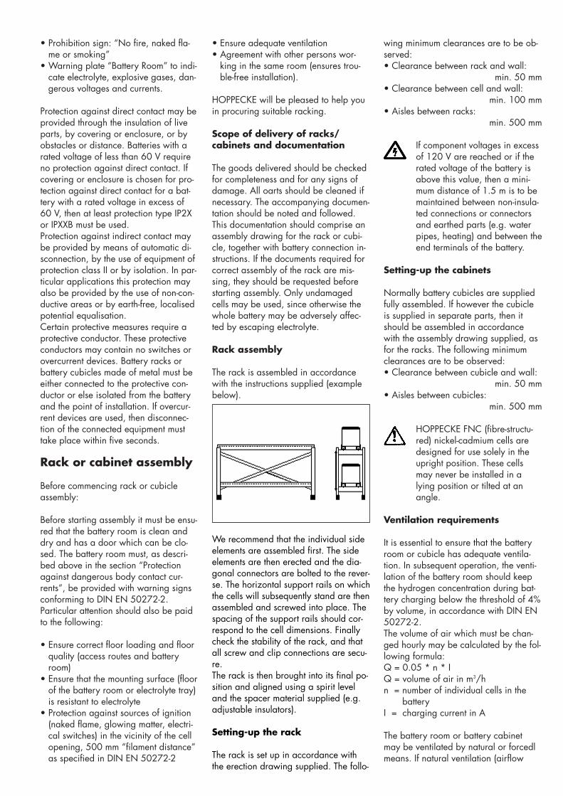
Rack assembly
The rack is assembled in accordancewith the instructions supplied (examplebelow).
wing minimum clearances are to be ob-served:• Clearance between rack and wall:
min. 50 mm• Clearance between cell and wall:
min. 100 mm• Aisles between racks:
min. 500 mm
If component voltages in excessof 120 V are reached or if therated voltage of the battery isabove this value, then a mini-mum distance of 1.5 m is to bemaintained between non-insula-ted connections or connectorsand earthed parts (e.g. waterpipes, heating) and between theend terminals of the battery.
Setting-up the cabinets
Normally battery cubicles are suppliedfully assembled. If however the cubicleis supplied in separate parts, then itshould be assembled in accordancewith the assembly drawing supplied, asfor the racks. The following minimumclearances are to be observed:• Clearance between cubicle and wall:
min. 50 mm• Aisles between cubicles:
min. 500 mm
HOPPECKE FNC (fibre-structu-red) nickel-cadmium cells aredesigned for use solely in theupright position. These cellsmay never be installed in alying position or tilted at anangle.
Ventilation requirements
It is essential to ensure that the batteryroom or cubicle has adequate ventila-tion. In subsequent operation, the venti-lation of the battery room should keepthe hydrogen concentration during bat-tery charging below the threshold of 4%by volume, in accordance with DIN EN50272-2.The volume of air which must be chan-ged hourly may be calculated by the fol-lowing formula:Q = 0.05 * n * IQ = volume of air in m3/hn = number of individual cells in the
batteryI = charging current in A
The battery room or battery cabinetmay be ventilated by natural or forcedlmeans. If natural ventilation (airflow
We recommend that the individual sideelements are assembled first. The sideelements are then erected and the dia-gonal connectors are bolted to the rever-se. The horizontal support rails on whichthe cells will subsequently stand are thenassembled and screwed into place. Thespacing of the support rails should cor-respond to the cell dimensions. Finallycheck the stability of the rack, and thatall screw and clip connections are secu-re.The rack is then brought into its final po-sition and aligned using a spirit leveland the spacer material supplied (e.g.adjustable insulators).
Setting-up the rack
The rack is set up in accordance withthe erection drawing supplied. The follo-
spatel
Typewritten Text
C135674 REV A 04APR14
spatel
Typewritten Text
(6 of 26)
spatel
Typewritten Text
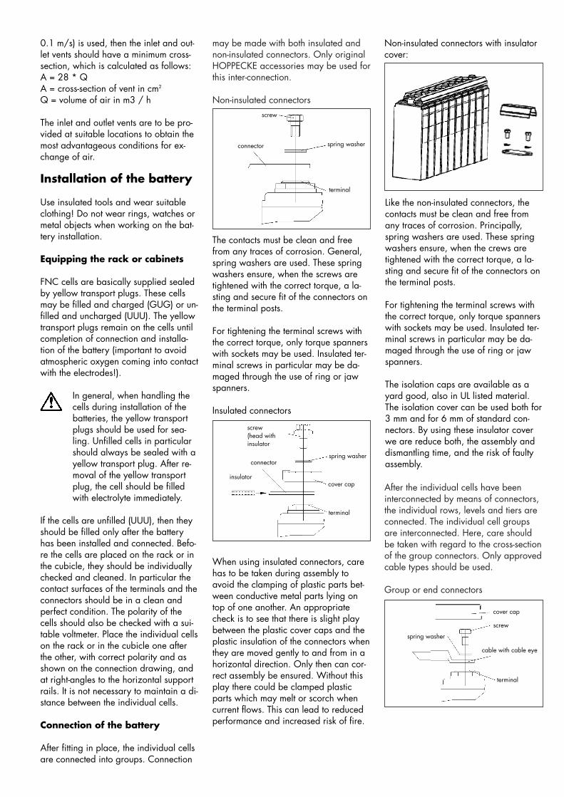
may be made with both insulated andnon-insulated connectors. Only originalHOPPECKE accessories may be used forthis inter-connection.
Non-insulated connectors
After the individual cells have beeninterconnected by means of connectors,the individual rows, levels and tiers areconnected. The individual cell groupsare interconnected. Here, care shouldbe taken with regard to the cross-sectionof the group connectors. Only approvedcable types should be used.
Group or end connectors
The contacts must be clean and freefrom any traces of corrosion. General,spring washers are used. These springwashers ensure, when the screws aretightened with the correct torque, a la-sting and secure fit of the connectors onthe terminal posts.
For tightening the terminal screws withthe correct torque, only torque spannerswith sockets may be used. Insulated ter-minal screws in particular may be da-maged through the use of ring or jawspanners.
Insulated connectors
screw
connector spring washer
terminal
When using insulated connectors, carehas to be taken during assembly toavoid the clamping of plastic parts bet-ween conductive metal parts lying ontop of one another. An appropriatecheck is to see that there is slight playbetween the plastic cover caps and theplastic insulation of the connectors whenthey are moved gently to and from in ahorizontal direction. Only then can cor-rect assembly be ensured. Without thisplay there could be clamped plasticparts which may melt or scorch whencurrent flows. This can lead to reducedperformance and increased risk of fire.
screw(head withinsulator
connector
insulator
terminal
spring washer
cover cap
0.1 m/s) is used, then the inlet and out-let vents should have a minimum cross-section, which is calculated as follows:A = 28 * QA = cross-section of vent in cm2
Q = volume of air in m3 / h
The inlet and outlet vents are to be pro-vided at suitable locations to obtain themost advantageous conditions for ex-change of air.
Installation of the battery
Use insulated tools and wear suitableclothing! Do not wear rings, watches ormetal objects when working on the bat-tery installation.
Equipping the rack or cabinets
FNC cells are basically supplied sealedby yellow transport plugs. These cellsmay be filled and charged (GUG) or un-filled and uncharged (UUU). The yellowtransport plugs remain on the cells untilcompletion of connection and installa-tion of the battery (important to avoidatmospheric oxygen coming into contactwith the electrodes!).
In general, when handling thecells during installation of thebatteries, the yellow transportplugs should be used for sea-ling. Unfilled cells in particularshould always be sealed with ayellow transport plug. After re-moval of the yellow transportplug, the cell should be filledwith electrolyte immediately.
If the cells are unfilled (UUU), then theyshould be filled only after the batteryhas been installed and connected. Befo-re the cells are placed on the rack or inthe cubicle, they should be individuallychecked and cleaned. In particular thecontact surfaces of the terminals and theconnectors should be in a clean andperfect condition. The polarity of thecells should also be checked with a sui-table voltmeter. Place the individual cellson the rack or in the cubicle one afterthe other, with correct polarity and asshown on the connection drawing, andat right-angles to the horizontal supportrails. It is not necessary to maintain a di-stance between the individual cells.
Connection of the battery
After fitting in place, the individual cellsare connected into groups. Connection
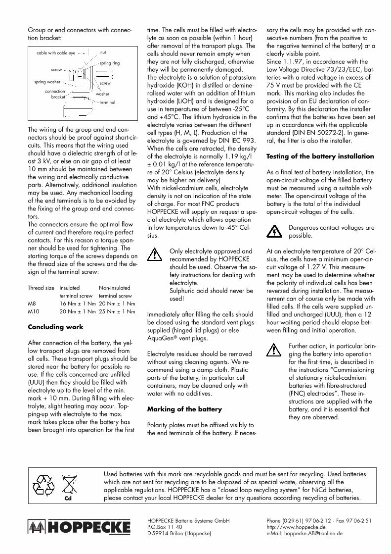
Non-insulated connectors with insulatorcover:
Like the non-insulated connectors, thecontacts must be clean and free fromany traces of corrosion. Principally,spring washers are used. These springwashers ensure, when the crews aretightened with the correct torque, a la-sting and secure fit of the connectors onthe terminal posts.
For tightening the terminal screws withthe correct torque, only torque spannerswith sockets may be used. Insulated ter-minal screws in particular may be da-maged through the use of ring or jawspanners.
The isolation caps are available as ayard good, also in UL listed material.The isolation cover can be used both for3 mm and for 6 mm of standard con-nectors. By using these insulator coverwe are reduce both, the assembly anddismantling time, and the risk of faultyassembly.
spring washer
terminal
cover cap
screw
cable with cable eye
spatel
Typewritten Text
C135674 REV A 04APR14
spatel
Typewritten Text
(7 of 26)
HOPPECKE Batterie Systeme GmbHP.O.Box 11 40D-59914 Brilon (Hoppecke)
Phone (0 29 61) 97 06-2 12 · Fax 97 06-2 51http://www.hoppecke.dee-Mail: [email protected]
Cd
Used batteries with this mark are recyclable goods and must be sent for recycling. Used batterieswhich are not sent for recycling are to be disposed of as special waste, observing all theapplicable regulations. HOPPECKE has a ”closed loop recycling system” for NiCd batteries,please contact your local HOPPECKE dealer for any questions according recycling of batteries.
HOPPECKE
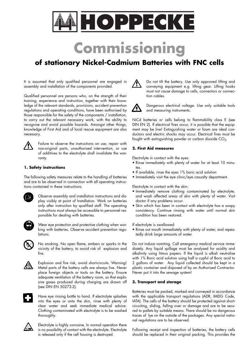
Group or end connectors with connec-tion bracket:
nut
spring ring
screw
washer
terminal
cable with cable eye
screw
spring washer
connectionbracket
The wiring of the group and end con-nectors should be proof against short-cir-cuits. This means that the wiring usedshould have a dielectric strength of at le-ast 3 kV, or else an air gap of at least10 mm should be maintained betweenthe wiring and electrically conductiveparts. Alternatively, additional insulationmay be used. Any mechanical loadingof the end terminals is to be avoided bythe fixing of the group and end connec-tors.The connectors ensure the optimal flowof current and therefore require perfectcontacts. For this reason a torque span-ner should be used for tightening. Thestarting torque of the screws depends onthe thread size of the screws and the de-sign of the terminal screw:
Thread size Insulated Non-insulatedterminal screw terminal screw
M8 16 Nm ± 1 Nm 20 Nm ± 1 NmM10 20 Nm ± 1 Nm 25 Nm ± 1 Nm
Concluding work
After connection of the battery, the yel-low transport plugs are removed fromall cells. These transport plugs should bestored near the battery for possible re-use. If the cells concerned are unfilled(UUU) then they should be filled withelectrolyte up to the level of the min.mark + 10 mm. During filling with elec-trolyte, slight heating may occur. Top-ping-up with electrolyte to the max.mark takes place after the battery hasbeen brought into operation for the first
time. The cells must be filled with electro-lyte as soon as possible (within 1 hour)after removal of the transport plugs. Thecells should never remain empty whenthey are not fully discharged, otherwisethey will be permanently damaged.The electrolyte is a solution of potassiumhydroxide (KOH) in distilled or demine-ralised water with an addition of lithiumhydroxide (LiOH) and is designed for ause in temperatures of between -25°Cand +45°C. The lithium hydroxide in theelectrolyte varies between the differentcell types (H, M, L). Production of theelectrolyte is governed by DIN IEC 993.When the cells are retracted, the densityof the electrolyte is normally 1.19 kg/l± 0.01 kg/l at the reference temperatu-re of 20° Celsius (electrolyte densitymay be higher on delivery)With nickel-cadmium cells, electrolytedensity is not an indication of the stateof charge. For most FNC productsHOPPECKE will supply on request a spe-cial electrolyte which allows operationin low temperatures down to -45° Cel-sius.
Only electrolyte approved andrecommended by HOPPECKEshould be used. Observe the sa-fety instructions for dealing withelectrolyte.Sulphuric acid should never beused!
Immediately after filling the cells shouldbe closed using the standard vent plugssupplied (hinged lid plugs) or elseAquaGen� vent plugs.
Electrolyte residues should be removedwithout using cleaning agents. We re-commend using a damp cloth. Plasticparts of the battery, in particular cellcontainers, may be cleaned only withwater with no additives.
Marking of the battery
Polarity plates must be affixed visibly tothe end terminals of the battery. If neces-
sary the cells may be provided with con-secutive numbers (from the positive tothe negative terminal of the battery) at aclearly visible point. Since 1.1.97, in accordance with theLow Voltage Directive 73/23/EEC, bat-teries with a rated voltage in excess of75 V must be provided with the CEmark. This marking also includes theprovision of an EU declaration of con-formity. By this declaration the installerconfirms that the batteries have been setup in accordance with the applicablestandard (DIN EN 50272-2). In gene-ral, the fitter is also the installer.
Testing of the battery installation
As a final test of battery installation, theopen-circuit voltage of the filled batterymust be measured using a suitable volt-meter. The open-circuit voltage of thebattery is the total of the individualopen-circuit voltages of the cells.
Dangerous contact voltages arepossible.
At an electrolyte temperature of 20° Cel-sius, the cells have a minimum open-cir-cuit voltage of 1.27 V. This measure-ment may be used to determine whetherthe polarity of individual cells has beenreversed during installation. The measu-rement can of course only be made withfilled cells. If the cells were supplied un-filled and uncharged (UUU), then a 12hour waiting period should elapse bet-ween filling and initial operation.
Further action, in particular brin-ging the battery into operationfor the first time, is described inthe instructions “Commissioningof stationary nickel-cadmiumbatteries with fibre-structured(FNC) electrodes”. These in-structions are supplied with thebattery, and it is essential thatthey are observed.
spatel
Typewritten Text
C135674 REV A 04APR14
spatel
Sticky Note
Marked set by spatel
spatel
Typewritten Text
(8 of 26)
DPenter
Text Box
HOPPECKECommissioning
of stationary Nickel-Cadmium Batteries with FNC cells
It is assumed that only qualified personnel are engaged inassembly and installation of the components provided.
Qualified personnel are persons who, on the strength of theirtraining, experience and instruction, together with their know-ledge of the relevant standards, provisions, accident preventionregulations and operating conditions, have been authorised bythose responsible for the safety of the components / installation,to carry out the relevant necessary work, with the ability torecognise and avoid possible hazards. Amongst other things,knowledge of First Aid and of local rescue equipment are alsonecessary.
Failure to observe the instructions on use, repair withnon-original parts, unauthorised intervention, or useof additives to the electrolyte shall invalidate the war-ranty.
1. Safety instructions
The following safety measures relate to the handling of batteriesand are to be observed in connection with all operating instruc-tions contained in these instructions.
Observe assembly and installation instructions and dis-play visibly at point of Installation. Work on batteriesonly after instruction by qualified staff. The operatinginstructions must always be accessible to personnel res-ponsible for dealing with batteries.
Wear eye protection and protective clothing when wor-king with batteries. Observe accident prevention regu-lations.
No smoking. No open flame, embers or sparks in thevicinity of the battery, to avoid risk of explosion andfire.
Explosion and fire risk, avoid short-circuits. Warning!Metal parts of the battery cells are always live. Neverplace foreign objects or tools on the battery. Ensureadequate ventilation of the battery room, so that explo-sive gases produced during charging are drawn off(see DIN EN 50272-2).
Have eye rinsing bottle to hand. If electrolyte splashesinto the eyes or onto the skin, rinse with plenty ofclear water and seek immediate medical advice.Clothing contaminated with electrolyte is to be washedthoroughly.
Electrolyte is highly corrosive. In normal operation thereis no possibility of contact with the electrolyte. Electrolyteis released only if the cell housing is destroyed.
Do not tilt the battery. Use only approved lifting andconveying equipment e.g. lifting gear. Lifting hooksmust not cause damage to cells, connectors or connec-tion cables.
Dangerous electrical voltage. Use only suitable toolsand measuring instruments.
NiCd batteries or cells belong to flammability class E (seeDIN EN 2). If electrical fires occur, it is possible that the equip-ment may be live! Extinguishing water or foam are ideal con-ductors and electric shocks may occur. Electrical fires must befought with extinguishing powder or carbon dioxide CO2.
2. First Aid measures
Electrolyte in contact with the eyes:• Rinse immediately with plenty of water for at least 10 minu-
tes.• If available, rinse the eyes 1% boric acid solution• Immediately visit the eye clinic/eye casualty department.
Electrolyte in contact with the skin:• Immediately remove clothing contaminated by electrolyte,
and wash affected areas of skin with plenty of water. Visitdoctor if any problems occur.
• Skin which has been in contact with electrolyte has a soapyconsistency. Continue rinsing with water until normal skincondition has been restored.
If electrolyte is swallowed:• Rinse out mouth immediately with plenty of water, and repea-
tedly drink large amounts of water.
Do not induce vomiting. Call emergency medical service imme-diately. Any liquid spillage must be analysed for acidity andalkalinity using litmus papers. If the liquid is alkali neutralisewith 1% Boric acid solution using half a cupful of Boric acid to2 gallons of water. Any liquid collected should be kept in aplastic container and disposed of by an Authorised Contractor.Never put it into the sewage system!
3. Transport and storage
Batteries must be packed, marked and conveyed in accordancewith the applicable transport regulations (ADR, IMDG Code,IATA). The cells of the battery should be protected against short-circuiting, sliding, falling over or damage and are to be secu-red to pallets by suitable means. There should be no dangeroustraces of lye on the outside of the packages. Any special natio-nal regulations are to be observed.
Following receipt and inspection of batteries, the battery cellsshould be replaced in their original packing. This provides the
spatel
Typewritten Text
spatel
Typewritten Text
C135675 REV A 04APR14
spatel
Typewritten Text
(9 of 26)
DPenter
Text Box
battery with good protection against damage while it is in stor-age prior to installation.
3.1 Tools
At all times insulated tools must be used to prevent the batteryfrom direct short circuits at the cells.Nickel Cadmium Battery electrolyte should never be allowed tocome into contact with lead acid batteries and Sulphuric acidfrom lead acid batteries should not be used in nickel cadmiumbatteries. Tools and instructions should be dedicated to one bat-tery or the other, not both. Cross contamination will destroy thebatteries. Any liquid spillage from nickel cadmium batteriesmust immediately be neutralised using half cup of boric acid to2 gallons of water (or 5% hydrochloric acid solution).Hydrometers, thermometers and voltmeters for lead acid batte-ries must be kept separate.
3.2 Transport
For transport the cells are provided with yellow transport plugsbefore departure from the factory.
In the case of used cells, the standard vent plugs (hinged lidplugs) or AquaGen� plugs are replaced by the yellow transportplugs. The standard vent plugs (hinged lid plugs) or AquaGen�plugs should be kept for possible subsequent use.• The cells should be transported in an upright position, secured
against sliding, tipping over or damage.• It is essential that the relevant national or international regu-
lations for the transport of dangerous goods are observed.
3.3 Storage
Basically, batteries must be stored on pallets in a dry area, ifpossible under a dustproof cover.The recommended storage temperature is 20°C.• The storage area should satisfy the following requirements:• The storage space must be dry• The storage space must be frost-free• The temperature of the storage area may not exceed 30°C• The battery must not be subject to any major fluctuations in
temperature• The battery cells may not be stacked• The battery cells should not be exposed to direct sunlight• Suitable binding material, a container, and a brush and sho-
vel should be available to deal with any spilt electrolyte.
4. General instructions on commissioning of the bat-tery
Both during and after charging, the battery produces explosivedetonating gas (a mixture of oxygen and hydrogen). Adequateventilation must therefore be provided, as specified in DIN EN50272-2. No electrical connections has to be connect or dis-connect up to 1 hour after charging. No naked flame, glowingmatter, electrical equipment or carriers of static electricity whichcould generate sparks are to be allowed in the vicinity of thebattery.
Metal parts of the battery can conduct voltage. Use insulatedtools and wear suitable clothing! Do not wear rings, watches ormetal objects while working on battery installations. The loadmust be disconnected from the battery. The battery must beconnected to the direct current supply with correct polarity (posi-tive terminal to positive terminal connector), with the batterycharger switched off and the load disconnected.
4.1 I and Ia charging
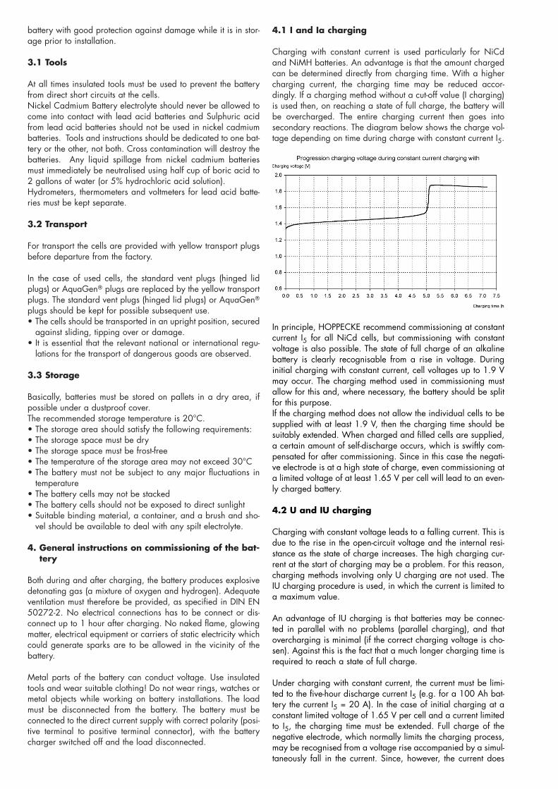
Charging with constant current is used particularly for NiCdand NiMH batteries. An advantage is that the amount chargedcan be determined directly from charging time. With a highercharging current, the charging time may be reduced accor-dingly. If a charging method without a cut-off value (I charging)is used then, on reaching a state of full charge, the battery willbe overcharged. The entire charging current then goes intosecondary reactions. The diagram below shows the charge vol-tage depending on time during charge with constant current I5.
In principle, HOPPECKE recommend commissioning at constantcurrent I5 for all NiCd cells, but commissioning with constantvoltage is also possible. The state of full charge of an alkalinebattery is clearly recognisable from a rise in voltage. Duringinitial charging with constant current, cell voltages up to 1.9 Vmay occur. The charging method used in commissioning mustallow for this and, where necessary, the battery should be splitfor this purpose.If the charging method does not allow the individual cells to besupplied with at least 1.9 V, then the charging time should besuitably extended. When charged and filled cells are supplied,a certain amount of self-discharge occurs, which is swiftly com-pensated for after commissioning. Since in this case the negati-ve electrode is at a high state of charge, even commissioning ata limited voltage of at least 1.65 V per cell will lead to an even-ly charged battery.
4.2 U and IU charging
Charging with constant voltage leads to a falling current. This isdue to the rise in the open-circuit voltage and the internal resi-stance as the state of charge increases. The high charging cur-rent at the start of charging may be a problem. For this reason,charging methods involving only U charging are not used. TheIU charging procedure is used, in which the current is limited toa maximum value.
An advantage of IU charging is that batteries may be connec-ted in parallel with no problems (parallel charging), and thatovercharging is minimal (if the correct charging voltage is cho-sen). Against this is the fact that a much longer charging time isrequired to reach a state of full charge.
Under charging with constant current, the current must be limi-ted to the five-hour discharge current I5 (e.g. for a 100 Ah bat-tery the current I5 = 20 A). In the case of initial charging at aconstant limited voltage of 1.65 V per cell and a current limitedto I5, the charging time must be extended. Full charge of thenegative electrode, which normally limits the charging process,may be recognised from a voltage rise accompanied by a simul-taneously fall in the current. Since, however, the current does
spatel
Typewritten Text
spatel
Typewritten Text
C135675 REV A 04APR14
spatel
Typewritten Text
spatel
Typewritten Text
(10 of 26)
spatel
Typewritten Text
not fall to zero, a further equalising charge off the positive elec-trode occurs. Only when the positive electrode is also fully char-ged does the user have the full capacity of the cell at their dis-posal.
The following table shows the specified charging time for initialcharging with limitation of charging voltage:
Voltage[V]
Time[h]
Current[A]
Capa-city [Ah]
Descpription
1.9/cell 7.5 I5 1.5*Cn Recommended method: the product of currentand time with a cell voltage of 1.9 V shouldcorrespond to 1.5 * Cn.
Example 100 Ah cell 1.9 V cell voltage:I = 20 A T = (100 Ah / 20 A) * 1.5 = 7.5 h
1,85/cell 10.5 I5 1.5*Cn In limiting the charging voltage an additional1,8/cell 13.5 factor must be introduced. If starting from 1.9 V1,75/cell 16.5 per cell the voltage is reduced by 0.5 V, then1,7/cell 19.5 charging time must be increased by 3 hours1,65/cell 22.5 in each case. Charging voltages of less than
1.65 V per cell are not allowed.
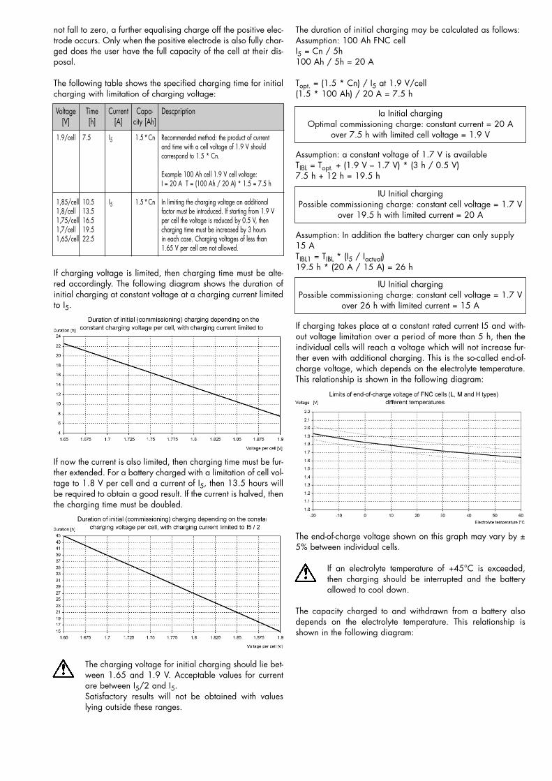
If charging voltage is limited, then charging time must be alte-red accordingly. The following diagram shows the duration ofinitial charging at constant voltage at a charging current limitedto I5.
If now the current is also limited, then charging time must be fur-ther extended. For a battery charged with a limitation of cell vol-tage to 1.8 V per cell and a current of I5, then 13.5 hours willbe required to obtain a good result. If the current is halved, thenthe charging time must be doubled.
The charging voltage for initial charging should lie bet-ween 1.65 and 1.9 V. Acceptable values for currentare between I5/2 and I5. Satisfactory results will not be obtained with valueslying outside these ranges.
The duration of initial charging may be calculated as follows:Assumption: 100 Ah FNC cellI5 = Cn / 5h100 Ah / 5h = 20 A
Topt. = (1.5 * Cn) / I5 at 1.9 V/cell(1.5 * 100 Ah) / 20 A = 7.5 h
Ia Initial chargingOptimal commissioning charge: constant current = 20 A
over 7.5 h with limited cell voltage = 1.9 V
Assumption: a constant voltage of 1.7 V is availableTIBL = Topt. + (1.9 V – 1.7 V) * (3 h / 0.5 V)7.5 h + 12 h = 19.5 h
IU Initial chargingPossible commissioning charge: constant cell voltage = 1.7 V
over 19.5 h with limited current = 20 A
Assumption: In addition the battery charger can only supply15 A TIBL1 = TIBL * (I5 / Iactual)19.5 h * (20 A / 15 A) = 26 h
IU Initial chargingPossible commissioning charge: constant cell voltage = 1.7 V
over 26 h with limited current = 15 A
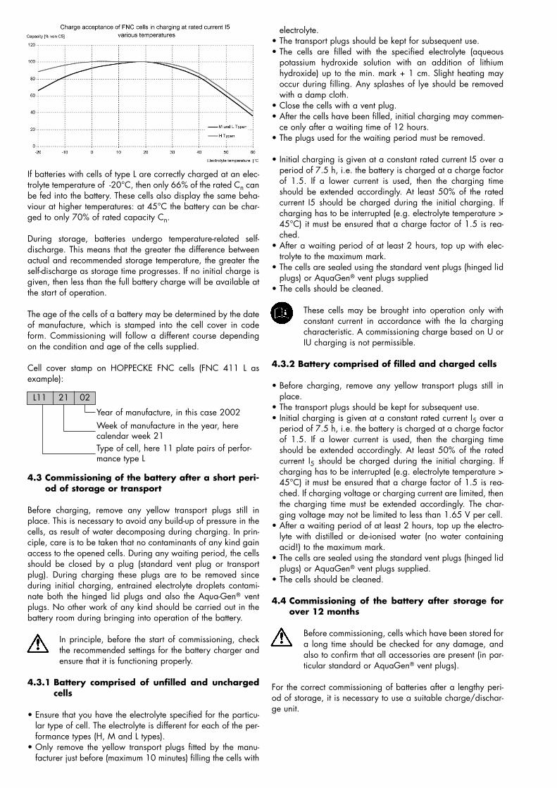
If charging takes place at a constant rated current I5 and with-out voltage limitation over a period of more than 5 h, then theindividual cells will reach a voltage which will not increase fur-ther even with additional charging. This is the so-called end-of-charge voltage, which depends on the electrolyte temperature.This relationship is shown in the following diagram:
The end-of-charge voltage shown on this graph may vary by ±5% between individual cells.
If an electrolyte temperature of +45°C is exceeded,then charging should be interrupted and the batteryallowed to cool down.
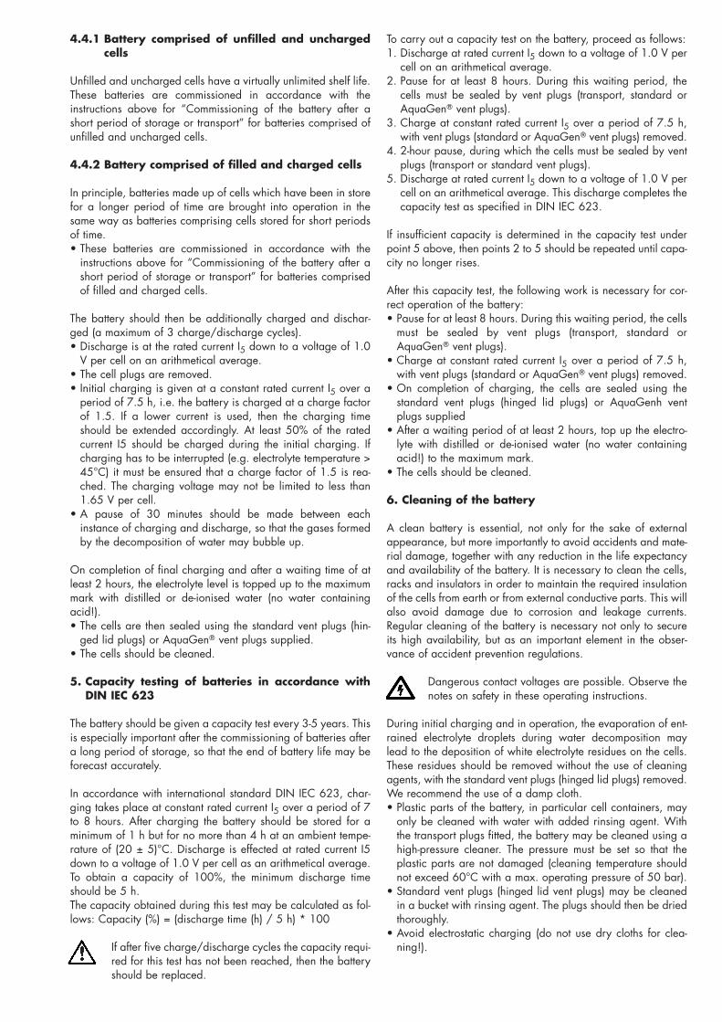
The capacity charged to and withdrawn from a battery alsodepends on the electrolyte temperature. This relationship isshown in the following diagram:
spatel
Typewritten Text
spatel
Typewritten Text
spatel
Typewritten Text
spatel
Typewritten Text
spatel
Typewritten Text
C135675 REV A 04APR14
spatel
Typewritten Text
(11 of 26)
spatel
Typewritten Text
If batteries with cells of type L are correctly charged at an elec-trolyte temperature of -20°C, then only 66% of the rated Cn canbe fed into the battery. These cells also display the same beha-viour at higher temperatures: at 45°C the battery can be char-ged to only 70% of rated capacity Cn.
During storage, batteries undergo temperature-related self-discharge. This means that the greater the difference betweenactual and recommended storage temperature, the greater theself-discharge as storage time progresses. If no initial charge isgiven, then less than the full battery charge will be available atthe start of operation.
The age of the cells of a battery may be determined by the dateof manufacture, which is stamped into the cell cover in codeform. Commissioning will follow a different course dependingon the condition and age of the cells supplied.
Cell cover stamp on HOPPECKE FNC cells (FNC 411 L asexample):
L11 21 02
Year of manufacture, in this case 2002Week of manufacture in the year, herecalendar week 21Type of cell, here 11 plate pairs of perfor-mance type L
4.3 Commissioning of the battery after a short peri-od of storage or transport
Before charging, remove any yellow transport plugs still inplace. This is necessary to avoid any build-up of pressure in thecells, as result of water decomposing during charging. In prin-ciple, care is to be taken that no contaminants of any kind gainaccess to the opened cells. During any waiting period, the cellsshould be closed by a plug (standard vent plug or transportplug). During charging these plugs are to be removed sinceduring initial charging, entrained electrolyte droplets contami-nate both the hinged lid plugs and also the Aqua-Gen� ventplugs. No other work of any kind should be carried out in thebattery room during bringing into operation of the battery.
In principle, before the start of commissioning, checkthe recommended settings for the battery charger andensure that it is functioning properly.
4.3.1 Battery comprised of unfilled and unchargedcells
• Ensure that you have the electrolyte specified for the particu-lar type of cell. The electrolyte is different for each of the per-formance types (H, M and L types).
• Only remove the yellow transport plugs fitted by the manu-facturer just before (maximum 10 minutes) filling the cells with
electrolyte.• The transport plugs should be kept for subsequent use.• The cells are filled with the specified electrolyte (aqueous
potassium hydroxide solution with an addition of lithiumhydroxide) up to the min. mark + 1 cm. Slight heating mayoccur during filling. Any splashes of lye should be removedwith a damp cloth.
• Close the cells with a vent plug.• After the cells have been filled, initial charging may commen-
ce only after a waiting time of 12 hours.• The plugs used for the waiting period must be removed.
• Initial charging is given at a constant rated current I5 over aperiod of 7.5 h, i.e. the battery is charged at a charge factorof 1.5. If a lower current is used, then the charging timeshould be extended accordingly. At least 50% of the ratedcurrent I5 should be charged during the initial charging. Ifcharging has to be interrupted (e.g. electrolyte temperature >45°C) it must be ensured that a charge factor of 1.5 is rea-ched.
• After a waiting period of at least 2 hours, top up with elec-trolyte to the maximum mark.
• The cells are sealed using the standard vent plugs (hinged lidplugs) or AquaGen� vent plugs supplied
• The cells should be cleaned.
These cells may be brought into operation only withconstant current in accordance with the Ia chargingcharacteristic. A commissioning charge based on U orIU charging is not permissible.
4.3.2 Battery comprised of filled and charged cells
• Before charging, remove any yellow transport plugs still inplace.
• The transport plugs should be kept for subsequent use.• Initial charging is given at a constant rated current I5 over a
period of 7.5 h, i.e. the battery is charged at a charge factorof 1.5. If a lower current is used, then the charging timeshould be extended accordingly. At least 50% of the ratedcurrent I5 should be charged during the initial charging. Ifcharging has to be interrupted (e.g. electrolyte temperature >45°C) it must be ensured that a charge factor of 1.5 is rea-ched. If charging voltage or charging current are limited, thenthe charging time must be extended accordingly. The char-ging voltage may not be limited to less than 1.65 V per cell.
• After a waiting period of at least 2 hours, top up the electro-lyte with distilled or de-ionised water (no water containingacid!) to the maximum mark.
• The cells are sealed using the standard vent plugs (hinged lidplugs) or AquaGen� vent plugs supplied.
• The cells should be cleaned.
4.4 Commissioning of the battery after storage forover 12 months
Before commissioning, cells which have been stored fora long time should be checked for any damage, andalso to confirm that all accessories are present (in par-ticular standard or AquaGen� vent plugs).
For the correct commissioning of batteries after a lengthy peri-od of storage, it is necessary to use a suitable charge/dischar-ge unit.
spatel
Typewritten Text
C135675 REV A 04APR14
spatel
Typewritten Text
(12 of 26)
4.4.1 Battery comprised of unfilled and unchargedcells
Unfilled and uncharged cells have a virtually unlimited shelf life.These batteries are commissioned in accordance with theinstructions above for “Commissioning of the battery after ashort period of storage or transport” for batteries comprised ofunfilled and uncharged cells.
4.4.2 Battery comprised of filled and charged cells
In principle, batteries made up of cells which have been in storefor a longer period of time are brought into operation in thesame way as batteries comprising cells stored for short periodsof time.• These batteries are commissioned in accordance with the
instructions above for “Commissioning of the battery after ashort period of storage or transport” for batteries comprisedof filled and charged cells.
The battery should then be additionally charged and dischar-ged (a maximum of 3 charge/discharge cycles).• Discharge is at the rated current I5 down to a voltage of 1.0
V per cell on an arithmetical average.• The cell plugs are removed.• Initial charging is given at a constant rated current I5 over a
period of 7.5 h, i.e. the battery is charged at a charge factorof 1.5. If a lower current is used, then the charging timeshould be extended accordingly. At least 50% of the ratedcurrent I5 should be charged during the initial charging. Ifcharging has to be interrupted (e.g. electrolyte temperature >45°C) it must be ensured that a charge factor of 1.5 is rea-ched. The charging voltage may not be limited to less than1.65 V per cell.
• A pause of 30 minutes should be made between eachinstance of charging and discharge, so that the gases formedby the decomposition of water may bubble up.
On completion of final charging and after a waiting time of atleast 2 hours, the electrolyte level is topped up to the maximummark with distilled or de-ionised water (no water containingacid!).• The cells are then sealed using the standard vent plugs (hin-
ged lid plugs) or AquaGen� vent plugs supplied.• The cells should be cleaned.
5. Capacity testing of batteries in accordance withDIN IEC 623
The battery should be given a capacity test every 3-5 years. Thisis especially important after the commissioning of batteries aftera long period of storage, so that the end of battery life may beforecast accurately.
In accordance with international standard DIN IEC 623, char-ging takes place at constant rated current I5 over a period of 7to 8 hours. After charging the battery should be stored for aminimum of 1 h but for no more than 4 h at an ambient tempe-rature of (20 ± 5)°C. Discharge is effected at rated current I5down to a voltage of 1.0 V per cell as an arithmetical average.To obtain a capacity of 100%, the minimum discharge timeshould be 5 h.The capacity obtained during this test may be calculated as fol-lows: Capacity (%) = (discharge time (h) / 5 h) * 100
If after five charge/discharge cycles the capacity requi-red for this test has not been reached, then the batteryshould be replaced.
To carry out a capacity test on the battery, proceed as follows:1. Discharge at rated current I5 down to a voltage of 1.0 V per
cell on an arithmetical average.2. Pause for at least 8 hours. During this waiting period, the
cells must be sealed by vent plugs (transport, standard orAquaGen� vent plugs).
3. Charge at constant rated current I5 over a period of 7.5 h,with vent plugs (standard or AquaGen� vent plugs) removed.
4. 2-hour pause, during which the cells must be sealed by ventplugs (transport or standard vent plugs).
5. Discharge at rated current I5 down to a voltage of 1.0 V percell on an arithmetical average. This discharge completes thecapacity test as specified in DIN IEC 623.
If insufficient capacity is determined in the capacity test underpoint 5 above, then points 2 to 5 should be repeated until capa-city no longer rises.
After this capacity test, the following work is necessary for cor-rect operation of the battery:• Pause for at least 8 hours. During this waiting period, the cells
must be sealed by vent plugs (transport, standard orAquaGen� vent plugs).
• Charge at constant rated current I5 over a period of 7.5 h,with vent plugs (standard or AquaGen� vent plugs) removed.
• On completion of charging, the cells are sealed using thestandard vent plugs (hinged lid plugs) or AquaGenh ventplugs supplied
• After a waiting period of at least 2 hours, top up the electro-lyte with distilled or de-ionised water (no water containingacid!) to the maximum mark.
• The cells should be cleaned.
6. Cleaning of the battery
A clean battery is essential, not only for the sake of externalappearance, but more importantly to avoid accidents and mate-rial damage, together with any reduction in the life expectancyand availability of the battery. It is necessary to clean the cells,racks and insulators in order to maintain the required insulationof the cells from earth or from external conductive parts. This willalso avoid damage due to corrosion and leakage currents.Regular cleaning of the battery is necessary not only to secureits high availability, but as an important element in the obser-vance of accident prevention regulations.
Dangerous contact voltages are possible. Observe thenotes on safety in these operating instructions.
During initial charging and in operation, the evaporation of ent-rained electrolyte droplets during water decomposition maylead to the deposition of white electrolyte residues on the cells.These residues should be removed without the use of cleaningagents, with the standard vent plugs (hinged lid plugs) removed.We recommend the use of a damp cloth.• Plastic parts of the battery, in particular cell containers, may
only be cleaned with water with added rinsing agent. Withthe transport plugs fitted, the battery may be cleaned using ahigh-pressure cleaner. The pressure must be set so that theplastic parts are not damaged (cleaning temperature shouldnot exceed 60°C with a max. operating pressure of 50 bar).
• Standard vent plugs (hinged lid vent plugs) may be cleanedin a bucket with rinsing agent. The plugs should then be driedthoroughly.
• Avoid electrostatic charging (do not use dry cloths for clea-ning!).
spatel
Typewritten Text
spatel
Typewritten Text
C135675 REV A 04APR14
spatel
Typewritten Text
(13 of 26)
7. Electrolyte
As the charge exchange medium, the electrolyte is of criticalimportance, ensuring optimal performance of the battery whenkept at the correct concentration and filling level. There will bea loss of performance if electrolyte levels are too low. Specialattention should therefore be given during maintenance to ensu-ring that electrolyte levels are correct. The electrolyte is compri-sed of aqueous potassium hydroxide solution (KOH) with anaddition of lithium hydroxide (LiOH), and is designed for use intemperatures ranging from -25 to +45°C. DIN IEC 993 appliesto the production of the electrolyte. When the cells have been inuse for some time the density of the electrolyte is usually 1.19kg/l-1 ± 0.01 kg/l-1 at the reference temperature of 20°Celsius (on delivery the electrolyte density may be higher). Theelectrolyte density is temperature-dependent and may be adju-sted using the correction factor 0.0005 kg/l-1 K-1. The lithiumhydroxide (LiOH) content varies for each of the different loadtypes L, M and H. The electrolyte retains its effectiveness throug-hout the entire life of the battery and does not need to be repla-ced. In nickel-cadmium cells, electrolyte density does not give anindication of the state of charge.
For the majority of FNC products HOPPECKE will provide onrequest a special electrolyte allowing operation even in the tem-perature range down to -45ºC.
8. Documentation
A record should be made during commissioning of the battery.A form for such a commissioning record is appended to theseinstructions. If your battery has more cells than provided for onthe form, please ask HOPPECKE Batterie Systeme for a suitableform for your purposes.
9. Taking the battery out of service
• Discharge at rated current I5 down to a voltage of 1.0 V percell.
• Replace the standard vent plugs (hinged lid vent plugs) orAquaGen� vent plugs by the yellow transport plugs. This isimportant to avoid atmospheric oxygen coming into contactwith the electrodes.
• Clean the battery including all cells• Store on pallets in a dry, frost-free room. The complete battery
or the individual cells should be provided with a cover.
In principle, when taking the battery out of service, the standardvent plugs (hinged lid vent plugs) or AquaGen� vent plugs onthe individual cells should be replaced by the yellow transportplugs. The standard vent plugs (hinged lid vent plugs) orAquaGen� vent plugs should be kept for subsequent use.
Depending on the length of storage after being taken out of ser-vice, the battery should be brought back into service again inaccordance with these instructions.
9.1 Disposal
Disassembly and disposal of the battery should be carried outonly by trained personnel. EC Directives 91156 (EEC) and9386 (EEC) must be observed. Your local HOPPECKE repre-sentative will be pleased to give you a quotation for properdisassembly and disposal of your battery. To take back all nolonger used batteries, is the long term target of the HOPPECKEcollection and recycling concept.
We have entered into a cooperation contract with two compa-nies to use there logistic network of collection points for Europe.Both recycler separate the cadmium content of the batteries bydistillation. This cadmium will be used for the production of cad-mium oxide for new batteries. This is the great advantage ofthese method. In this way we have a “Closed Loop System“ forthe cadmium content of the recycled batteries.
Further action, in particular the operation and mainte-nance of the battery, is described in the instructions“Operation and maintenance of stationary nickel-cad-mium batteries with FNC cells”. It is essential that theseinstructions, which are supplied with the battery, arefollowed.
Used batteries with this symbol are recyclable goodsand must be sent for recycling. Used batteries whichare not sent for recycling are to be disposed of as spe-cial waste under the appropriate regulations.Hoppecke have a “closed loop” recycling system forNiCd batteries. Your local HOPPECKE representativewill be pleased to give you a quotation for disposal ofyour battery.
Cd
spatel
Typewritten Text
spatel
Typewritten Text
C135675 REV A 04APR14
spatel
Typewritten Text
spatel
Typewritten Text
(14 of 26)
spatel
Typewritten Text
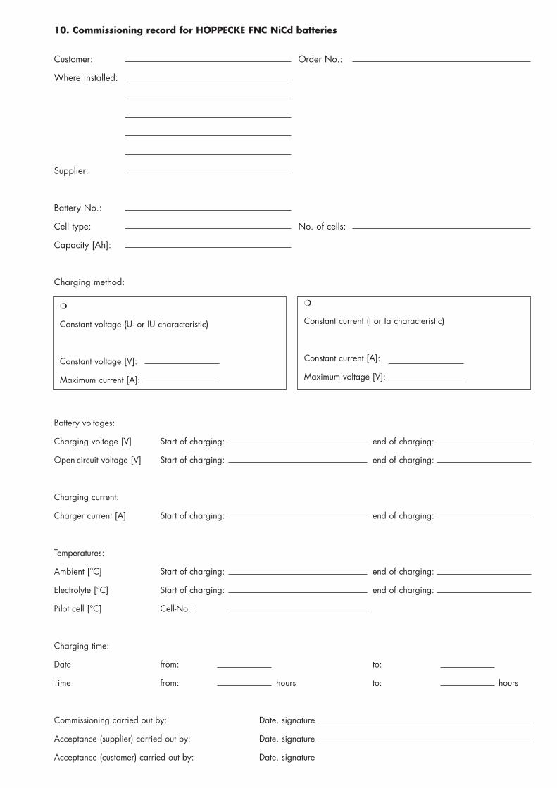
10. Commissioning record for HOPPECKE FNC NiCd batteries
Customer: Order No.:
Where installed:
Supplier:
Battery No.:
Cell type: No. of cells:
Capacity [Ah]:
Charging method:
❍
Constant voltage (U- or IU characteristic)
Constant voltage [V]:
Maximum current [A]:
❍
Constant current (I or Ia characteristic)
Constant current [A]:
Maximum voltage [V]:
Battery voltages:
Charging voltage [V] Start of charging: end of charging:
Open-circuit voltage [V] Start of charging: end of charging:
Charging current:
Charger current [A] Start of charging: end of charging:
Temperatures:
Ambient [°C] Start of charging: end of charging:
Electrolyte [°C] Start of charging: end of charging:
Pilot cell [°C] Cell-No.:
Charging time:
Date from: to:
Time from: hours to: hours
Commissioning carried out by: Date, signature
Acceptance (supplier) carried out by: Date, signature
Acceptance (customer) carried out by: Date, signature
spatel
Typewritten Text
spatel
Typewritten Text
C135675 REV A 04APR14
spatel
Typewritten Text
(15 of 26)
spatel
Typewritten Text
DPenter
Text Box
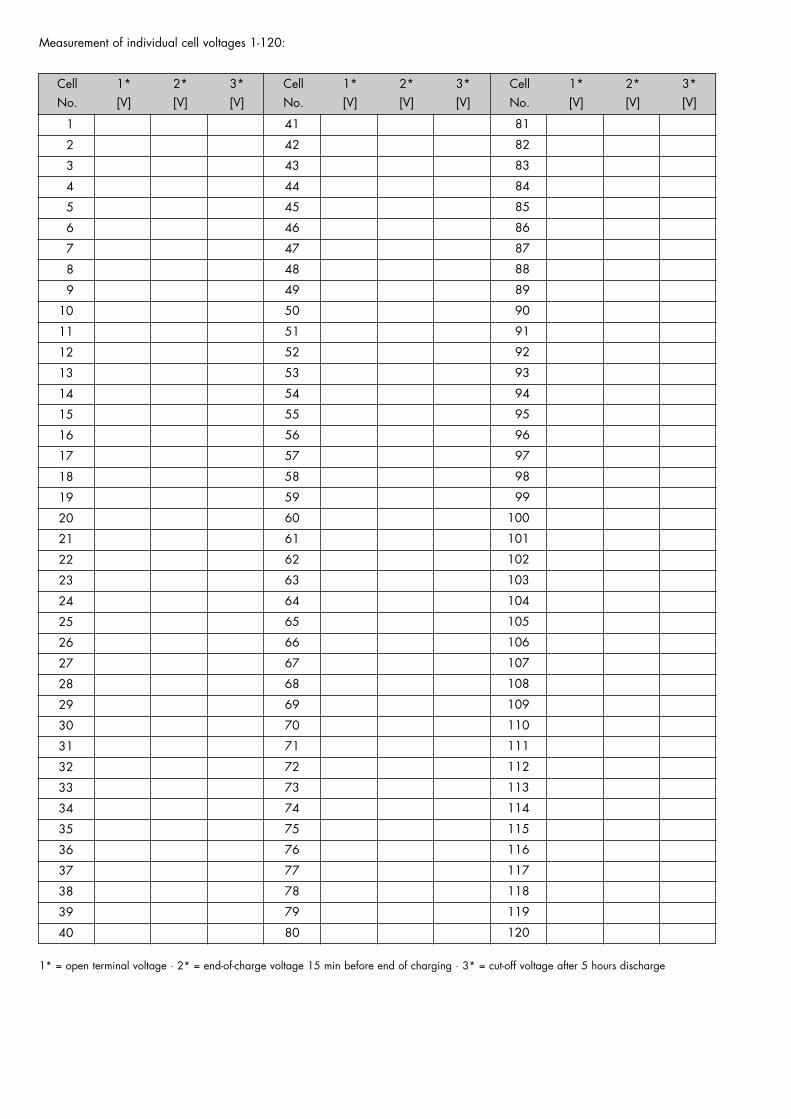
1* = open terminal voltage · 2* = end-of-charge voltage 15 min before end of charging · 3* = cut-off voltage after 5 hours discharge
Measurement of individual cell voltages 1-120:
Cell 1* 2* 3*No. [V] [V] [V]
Cell 1* 2* 3*No. [V] [V] [V]
Cell 1* 2* 3*No. [V] [V] [V]
1
2
3
4
5
6
7
8
9
10
11
12
13
14
15
16
17
18
19
20
21
22
23
24
25
26
27
28
29
30
31
32
33
34
35
36
37
38
39
40
41
42
43
44
45
46
47
48
49
50
51
52
53
54
55
56
57
58
59
60
61
62
63
64
65
66
67
68
69
70
71
72
73
74
75
76
77
78
79
80
81
82
83
84
85
86
87
88
89
90
91
92
93
94
95
96
97
98
99
100
101
102
103
104
105
106
107
108
109
110
111
112
113
114
115
116
117
118
119
120
spatel
Typewritten Text
C135675 REV A 04APR14
spatel
Typewritten Text
spatel
Typewritten Text
(16 of 26)
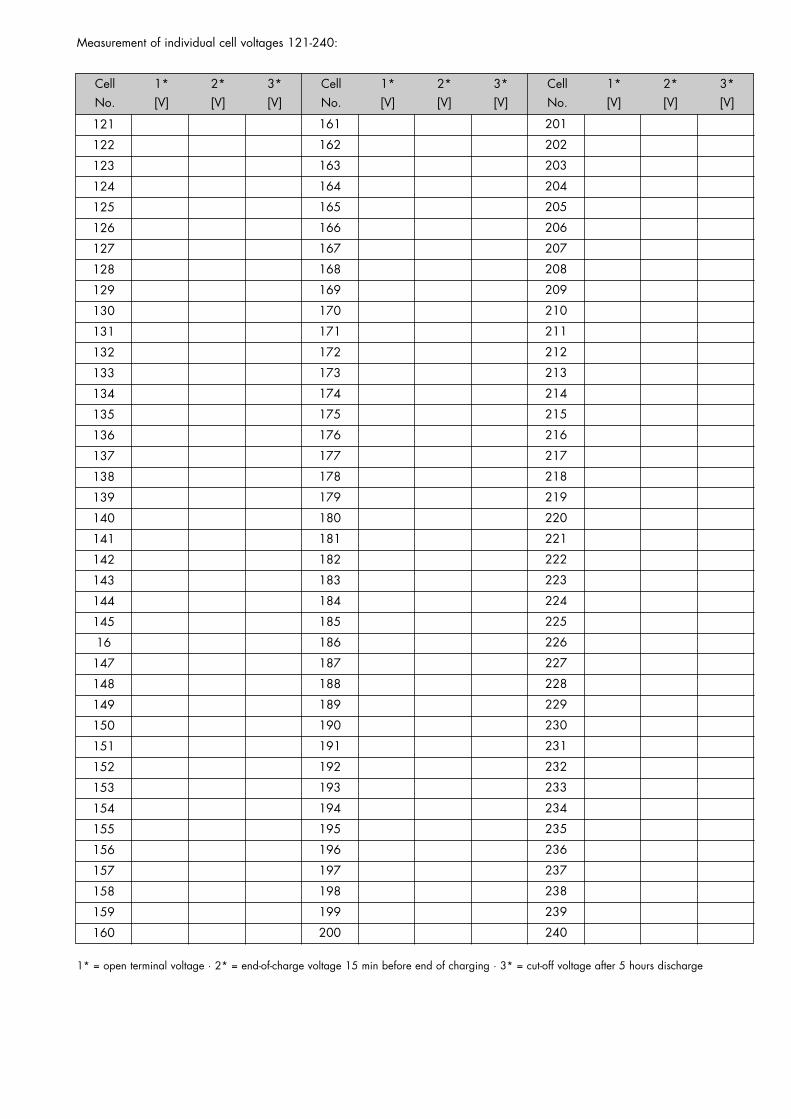
1* = open terminal voltage · 2* = end-of-charge voltage 15 min before end of charging · 3* = cut-off voltage after 5 hours discharge
Measurement of individual cell voltages 121-240:
Cell 1* 2* 3*No. [V] [V] [V]
Cell 1* 2* 3*No. [V] [V] [V]
Cell 1* 2* 3*No. [V] [V] [V]
121
122
123
124
125
126
127
128
129
130
131
132
133
134
135
136
137
138
139
140
141
142
143
144
145
16
147
148
149
150
151
152
153
154
155
156
157
158
159
160
161
162
163
164
165
166
167
168
169
170
171
172
173
174
175
176
177
178
179
180
181
182
183
184
185
186
187
188
189
190
191
192
193
194
195
196
197
198
199
200
201
202
203
204
205
206
207
208
209
210
211
212
213
214
215
216
217
218
219
220
221
222
223
224
225
226
227
228
229
230
231
232
233
234
235
236
237
238
239
240
spatel
Typewritten Text
C135675 REV A 04APR14
spatel
Typewritten Text
(17 of 26)
spatel
Typewritten Text
HOPPECKE Batterie Systeme GmbHP.O.Box 11 40D-59914 Brilon (Hoppecke)
Phone (0 29 61) 97 06-2 12 · Fax 97 06-2 51http://www.hoppecke.dee-Mail: [email protected] Te
il-N
r. 41
4020
3121
/07.
03/1
H
P
rinte
d in
Ger
man
y
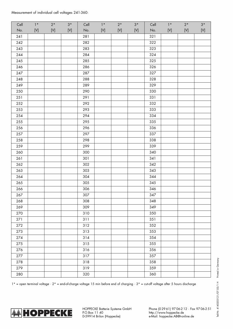
1* = open terminal voltage · 2* = end-of-charge voltage 15 min before end of charging · 3* = cut-off voltage after 5 hours discharge
Measurement of individual cell voltages 241-360:
Cell 1* 2* 3*No. [V] [V] [V]
Cell 1* 2* 3*No. [V] [V] [V]
Cell 1* 2* 3*No. [V] [V] [V]
241
242
243
244
245
246
247
248
249
250
251
252
253
254
255
256
257
258
259
260
261
262
263
264
265
266
267
268
269
270
271
272
273
274
275
276
277
278
279
280
281
282
283
284
285
286
287
288
289
290
291
292
293
294
295
296
297
298
299
300
301
302
303
304
305
306
307
308
309
310
311
312
313
314
315
316
317
318
319
320
321
322
323
324
325
326
327
328
329
330
331
332
333
334
335
336
337
338
339
340
341
342
343
344
345
346
347
348
349
350
351
352
353
354
355
356
357
358
359
360
spatel
Typewritten Text
C135675 REV A 04APR14
spatel
Typewritten Text
(18 of 26)
DPenter
Text Box
HOPPECKEOperation and Maintenance
of stationary Nickel-Cadmium Batteries with FNC cells
It is assumed that only qualified personnel are engaged in assembly and installation of the components provided. Qualifiedpersonnel are persons who, on the strength of their training, experience and instruction, together with their knowledge ofthe relevant standards, provisions, accident prevention regulations and operating conditions, have been authorised by thoseresponsible for the safety of the components / installation, to carry out the relevant necessary work, with the ability to reco-gnise and avoid possible hazards. Amongst other things, knowledge of First Aid and of local rescue equipment are alsonecessary.
Failure to observe the instructions on use, repair with non-original parts, unauthorised intervention, or use of addi-tives to the electrolyte shall invalidate the warranty.
1. Safety instructions
The following safety measures relate to the handling of batteries and are to be observed in connection with all operatinginstructions contained in these instructions.
Observe assembly and installation instructions and display visibly at point of installation.Work on batteries only after instruction by qualified staff. The operating instructions must always be accessible topersonnel responsible for dealing with batteries.
Wear eye protection and protective clothing when working with batteries.Observe accident prevention regulations.
No smoking. No open flame, embers or sparks in the vicinity of the battery, to avoid risk of explosion and fire.
Explosion and fire risk, avoid short-circuits. Warning! Metal parts of the battery cells are always live. Never placeforeign objects or tools on the battery. Ensure adequate ventilation of the battery room, so that explosive gases pro-duced during charging are drawn off (see DIN EN 50272-2).
Have eye rinsing bottle to hand. If electrolyte splashes into the eyes or onto the skin, rinse with plenty of clear waterand seek immediate medical advice. Clothing contaminated with electrolyte is to be washed thoroughly.
Electrolyte is highly corrosive. In normal operation there is no possibility of contact with the electrolyte. Electrolyteis released only if the cell housing is destroyed.
Do not tilt the battery!Use only approved lifting and conveying equipment e.g. lifting gear. Lifting hooks must not cause damage to cells,connectors or connection cables.
Dangerous electrical voltage. Use only suitable tools and measuring instruments.
NiCd batteries or cells belong to flammability class E (see DIN EN 2). If electrical fires occur, it is possible that the equip-ment may be live! Extinguishing water or foam are ideal conductors and electric shocks may occur. Electrical fires must befought with extinguishing powder or carbon dioxide CO2.
2. First Aid measures
Electrolyte in contact with the eyes:• Rinse immediately with plenty of water for at least 10 minutes.• If available, rinse the eyes 1% boric acid solution• Immediately visit the eye clinic/eye casualty department.
spatel
Typewritten Text
C135676 REV A 04APR14
spatel
Typewritten Text
spatel
Typewritten Text
(19 of 26)
DPenter
Text Box
Electrolyte in contact with the skin:• Immediately remove clothing contaminated by electrolyte, and wash affected areas of skin with plenty of water. Visit doc-
tor if any problems occur.• Skin which has been in contact with electrolyte has a soapy consistency. Continue rinsing with water until normal skin con-
dition has been restored.
If electrolyte is swallowed:• Rinse out mouth immediately with plenty of water, and repeatedly drink large amounts of water.
Do not induce vomiting. Call emergency medical service immediately. Any liquid spillage must be analysed for acidity andalkalinity using litmus papers. If the liquid is alkali neutralise with 1% Boric acid solution using half a cupful of Boric acid to2 gallons of water. Any liquid collected should be kept in a plastic container and disposed of by an Authorised Contractor.Never put it into the sewage system!
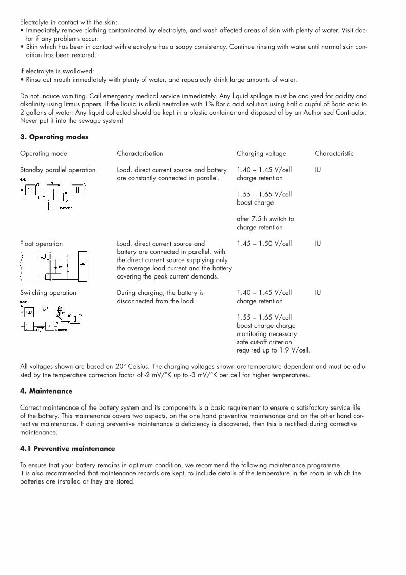
3. Operating modes
Operating mode Characterisation Charging voltage Characteristic
Standby parallel operation Load, direct current source and battery 1.40 – 1.45 V/cell IUare constantly connected in parallel. charge retention
1.55 – 1.65 V/cellboost charge
after 7.5 h switch tocharge retention
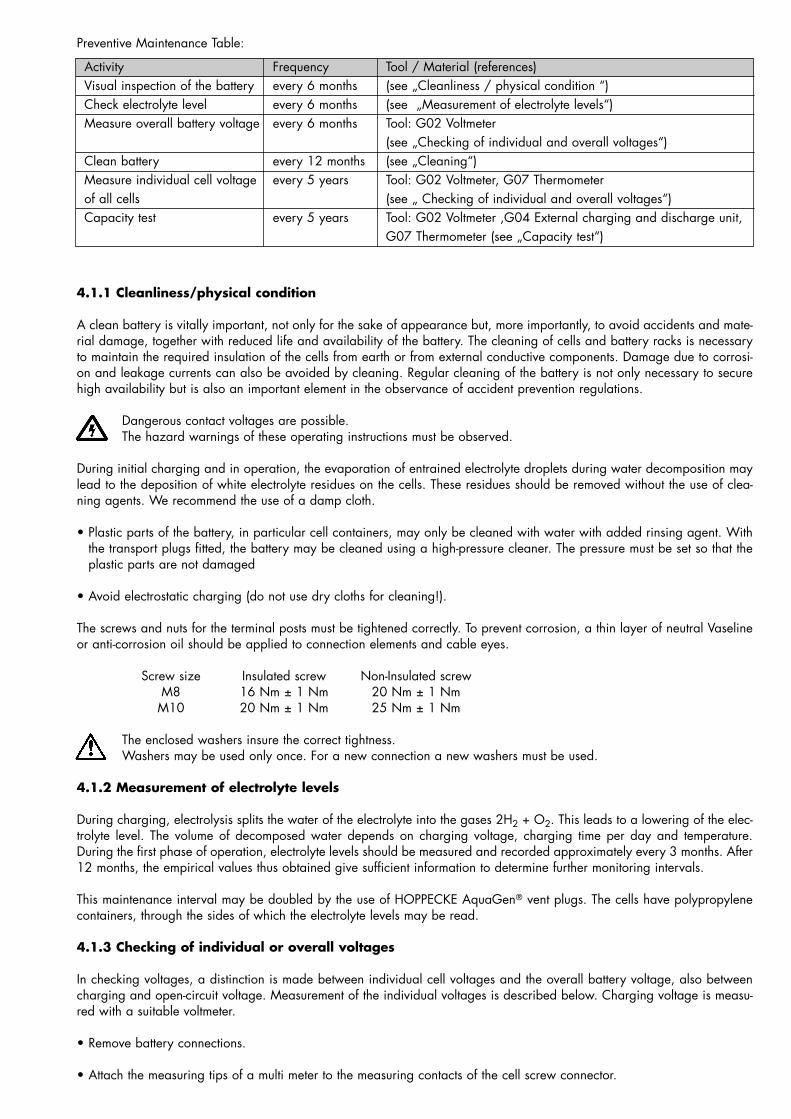
Float operation Load, direct current source and 1.45 – 1.50 V/cell IUbattery are connected in parallel, withthe direct current source supplying onlythe average load current and the batterycovering the peak current demands.
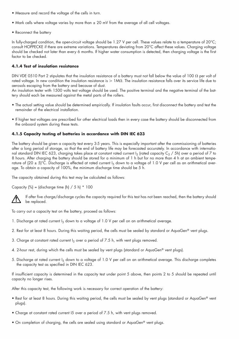
Switching operation During charging, the battery is 1.40 – 1.45 V/cell IUdisconnected from the load. charge retention
1.55 – 1.65 V/cell boost charge chargemonitoring necessarysafe cut-off criterionrequired up to 1.9 V/cell.
All voltages shown are based on 20° Celsius. The charging voltages shown are temperature dependent and must be adju-sted by the temperature correction factor of -2 mV/°K up to -3 mV/°K per cell for higher temperatures.
4. Maintenance
Correct maintenance of the battery system and its components is a basic requirement to ensure a satisfactory service lifeof the battery. This maintenance covers two aspects, on the one hand preventive maintenance and on the other hand cor-rective maintenance. If during preventive maintenance a deficiency is discovered, then this is rectified during correctivemaintenance.
4.1 Preventive maintenance
To ensure that your battery remains in optimum condition, we recommend the following maintenance programme. It is also recommended that maintenance records are kept, to include details of the temperature in the room in which thebatteries are installed or they are stored.
spatel
Typewritten Text
spatel
Typewritten Text
spatel
Typewritten Text
C135676 REV A 04APR14
spatel
Typewritten Text
spatel
Typewritten Text
(20 of 26)
Preventive Maintenance Table:
Activity Frequency Tool / Material (references)Visual inspection of the battery every 6 months (see „Cleanliness / physical condition “) Check electrolyte level every 6 months (see „Measurement of electrolyte levels“) Measure overall battery voltage every 6 months Tool: G02 Voltmeter
(see „Checking of individual and overall voltages“)Clean battery every 12 months (see „Cleaning“)Measure individual cell voltage every 5 years Tool: G02 Voltmeter, G07 Thermometerof all cells (see „ Checking of individual and overall voltages“)Capacity test every 5 years Tool: G02 Voltmeter ,G04 External charging and discharge unit,
G07 Thermometer (see „Capacity test“)
4.1.1 Cleanliness/physical condition
A clean battery is vitally important, not only for the sake of appearance but, more importantly, to avoid accidents and mate-rial damage, together with reduced life and availability of the battery. The cleaning of cells and battery racks is necessaryto maintain the required insulation of the cells from earth or from external conductive components. Damage due to corrosi-on and leakage currents can also be avoided by cleaning. Regular cleaning of the battery is not only necessary to securehigh availability but is also an important element in the observance of accident prevention regulations.
Dangerous contact voltages are possible.The hazard warnings of these operating instructions must be observed.
During initial charging and in operation, the evaporation of entrained electrolyte droplets during water decomposition maylead to the deposition of white electrolyte residues on the cells. These residues should be removed without the use of clea-ning agents. We recommend the use of a damp cloth.
• Plastic parts of the battery, in particular cell containers, may only be cleaned with water with added rinsing agent. Withthe transport plugs fitted, the battery may be cleaned using a high-pressure cleaner. The pressure must be set so that theplastic parts are not damaged
• Avoid electrostatic charging (do not use dry cloths for cleaning!).
The screws and nuts for the terminal posts must be tightened correctly. To prevent corrosion, a thin layer of neutral Vaselineor anti-corrosion oil should be applied to connection elements and cable eyes.
Screw size Insulated screw Non-Insulated screwM8 16 Nm ± 1 Nm 20 Nm ± 1 Nm
M10 20 Nm ± 1 Nm 25 Nm ± 1 Nm
The enclosed washers insure the correct tightness.Washers may be used only once. For a new connection a new washers must be used.
4.1.2 Measurement of electrolyte levels
During charging, electrolysis splits the water of the electrolyte into the gases 2H2 + O2. This leads to a lowering of the elec-trolyte level. The volume of decomposed water depends on charging voltage, charging time per day and temperature.During the first phase of operation, electrolyte levels should be measured and recorded approximately every 3 months. After12 months, the empirical values thus obtained give sufficient information to determine further monitoring intervals.
This maintenance interval may be doubled by the use of HOPPECKE AquaGen� vent plugs. The cells have polypropylenecontainers, through the sides of which the electrolyte levels may be read.
4.1.3 Checking of individual or overall voltages
In checking voltages, a distinction is made between individual cell voltages and the overall battery voltage, also betweencharging and open-circuit voltage. Measurement of the individual voltages is described below. Charging voltage is measu-red with a suitable voltmeter.
• Remove battery connections.
• Attach the measuring tips of a multi meter to the measuring contacts of the cell screw connector.
spatel
Typewritten Text
C135676 REV A 04APR14
spatel
Typewritten Text
spatel
Typewritten Text
(21 of 26)
spatel
Typewritten Text
• Measure and record the voltage of the cells in turn.
• Mark cells where voltage varies by more than ± 20 mV from the average of all cell voltages.
• Reconnect the battery
In fully-charged condition, the open-circuit voltage should be 1.27 V per cell. These values relate to a temperature of 20°C;consult HOPPECKE if there are extreme variations. Temperatures deviating from 20°C affect these values. Charging voltageshould be checked not later than every 6 months. If higher water consumption is detected, then charging voltage is the firstfactor to be checked.
4.1.4 Test of insulation resistance
DIN VDE 0510 Part 2 stipulates that the insulation resistance of a battery must not fall below the value of 100 � per volt ofrated voltage. In new condition the insulation resistance is � 1M�. The insulation resistance falls over its service life due toaerosols escaping from the battery and because of dust.An insulation tester with 1500 volts test voltage should be used. The positive terminal and the negative terminal of the bat-tery should each be measured against the metal parts of the rollers.
• The actual setting value should be determined empirically. If insulation faults occur, first disconnect the battery and test theremainder of the electrical installation.
• If higher test voltages are prescribed for other electrical loads then in every case the battery should be disconnected fromthe onboard system during these tests.
4.1.5 Capacity testing of batteries in accordance with DIN IEC 623
The battery should be given a capacity test every 3-5 years. This is especially important after the commissioning of batteriesafter a long period of storage, so that the end of battery life may be forecasted accurately. In accordance with internatio-nal standard DIN IEC 623, charging takes place at constant rated current I5 (rated capacity C5 / 5h) over a period of 7 to8 hours. After charging the battery should be stored for a minimum of 1 h but for no more than 4 h at an ambient tempe-rature of (20 ± 5)°C. Discharge is effected at rated current I5 down to a voltage of 1.0 V per cell as an arithmetical aver-age. To obtain a capacity of 100%, the minimum discharge time should be 5 h.
The capacity obtained during this test may be calculated as follows:
Capacity (%) = (discharge time (h) / 5 h) * 100
If after five charge/discharge cycles the capacity required for this test has not been reached, then the battery shouldbe replaced.
To carry out a capacity test on the battery, proceed as follows:
1. Discharge at rated current I5 down to a voltage of 1.0 V per cell on an arithmetical average.
2. Rest for at least 8 hours. During this waiting period, the cells must be sealed by standard or AquaGen� vent plugs.
3. Charge at constant rated current I5 over a period of 7.5 h, with vent plugs removed.
4. 2-hour rest, during which the cells must be sealed by vent plugs (standard or AquaGen� vent plugs).
5. Discharge at rated current I5 down to a voltage of 1.0 V per cell on an arithmetical average. This discharge completesthe capacity test as specified in DIN IEC 623.
If insufficient capacity is determined in the capacity test under point 5 above, then points 2 to 5 should be repeated untilcapacity no longer rises.
After this capacity test, the following work is necessary for correct operation of the battery:
• Rest for at least 8 hours. During this waiting period, the cells must be sealed by vent plugs (standard or AquaGen� ventplugs).
• Charge at constant rated current I5 over a period of 7.5 h, with vent plugs removed.
• On completion of charging, the cells are sealed using standard or AquaGen� vent plugs.
spatel
Typewritten Text
spatel
Typewritten Text
spatel
Typewritten Text
C135676 REV A 04APR14
spatel
Typewritten Text
(22 of 26)
• After a waiting period of at least 2 hours, top up the electrolyte with distilled or de-ionised water (no water containingacid!) to the maximum mark.
The capacity test forms part of reconditioning charging. If after several attempts at reconditioning the result of capacitytesting is not satisfactory, then the battery has reached the end of its life.
4.1.6 Cleaning
A clean battery is absolutely essential to avoid accidents and material damage, also to maximise battery life and availabi-lity. It is necessary to clean cell holders, trays, racks and insulators in order to maintain the required insulation of the cellsfrom one another, from earth, or from external conductive parts. Cleaning also prevents damage from corrosion and lea-kage current.DIN VDE 0510 Part 2 specifies that the insulation resistance shall not fall below a value of 100 � per volt of cell voltage.Depending on the location and duration of usage it is impossible to avoid deposits of dust on the battery. Small amounts ofelectrolyte particles which escape during battery charging above the gassing voltage form a more or less conductive layeron the cells or the block lids. So-called leakage currents then flow through this layer. This results in enhanced and varyingself-discharge of the individual cells.If higher leakage currents flow, then electrical sparks can not be ruled out. Such sparks may cause an explosion of the char-ging gas (detonating gas) escaping from the cell plugs.Consequently the cleaning of batteries is necessary not only to ensure high availability, but also as an essential part of acci-dent prevention.
It is essential that the following instructions are followed when cleaning batteries in installed condition:
• The cell plugs must not be removed or opened. Instead, the cells must remain closed.
• Plastic parts of the battery, in particular the cell containers, may be cleaned only with water or with cleaning cloths soa-ked in water without additives.
• After cleaning, dry the battery surface by suitable means, e.g. compressed air or cleaning cloths.
• Any fluid which has entered the battery tray must be siphoned off, and disposed of in accordance with the regulationsgoverning waste and residues.
4.2 Corrective maintenance
Corrective maintenance table:
Activity Frequency Tools / Material (references)Top up with distilled water every 6-12 months Tool: G06 Funnel
Material: Distilled water (see „Topping-up the electrolyte“)Reconditioning charge every 5 years Tool: G02 Voltmeter ,G04 External Charging and Discharge unit,
G07 Thermometer (see „Capacity test“,„Reconditioning of the battery“)
4.2.1 Topping-up the electrolyte with distilled water
Nickel-cadmium batteries are filled with highly caustic potassium hydroxide solution (KOH) and an additive of lithium-hydro-xide (LiOH) in accordance with DIN 43530. When working with the batteries, protective clothing such as rubber glovesand eye protection must be worn. If nevertheless electrolyte comes into contact with skin or eyes, then the latter should berinsed immediately under running water, after which medical advice should be sought without delay.
If the electrolyte levels of the battery are below the mid-point between the min. and max. marks, the should be top-ped-up to the max. mark with distilled water.
Any splashes of electrolyte or water should be removed with a damp cloth. The fibre-structure technology allows the use ofpure active materials. Additives such as graphite to increase the conductivity of the positive electrodes are no longer neces-sary. Any carbonisation of the potassium hydroxide solution due to the electrodes is therefore ruled out.
No change of electrolyte is necessary during the entire life of the battery.
spatel
Typewritten Text
C135676 REV A 04APR14
spatel
Typewritten Text
(23 of 26)
4.2.2 Reconditioning the battery
The decline in the state of charge of a battery can be reversed only by charging at constant current. This is described asreconditioning of the battery. In order to carry out this reconditioning , the battery must be charged and discharged in adefined manner. Before this charging, the battery should be disconnected from the onboard system, since during recondi-tioning of the battery with constant current, cell voltages of up to 1.9 V may occur. Also during this charging, a larger amo-unt of water is decomposed than during normal operation, so that provision for adequate ventilation must be ensured, inaccordance with DIN VDE 0510.
The following discharge/charging procedure is recommended:
1. Discharge the battery at I5 down to 1.00 volt/cell on the arithmetic average.
2. Rest � 8 hours, if possible overnight
3. Charge at constant current I5 over 7.5 hours
4. Rest for 2 hours
5. Discharge at I5 down to 1.0 volt per cell on the arithmetic average (capacity test)
6. Rest � 8 hours, if possible overnight
7. Charge at constant current I5 over 7.5 hours
If the capacity test reveals insufficient capacity then the tests covered by points 1 to 5 above are to be repeated until capa-city no longer rises. The same criteria also apply to capacity tests.
5. Fault-finding
5.1 Excessive water consumption
Loss of water occurs on the one hand due to evaporation, but also due to the decomposing of the water into oxygen andhydrogen gas during charging. The first thing to check is the charging voltage in the system. If this is correct, then proceedas follows:
• Measure the individual cell voltages during chargingIf the individual cell voltages vary by more than ± 50 mV from the average, then the battery should be removed, andthe following measurement undertaken after 2 days’ rest:
• Measure the open-circuit voltage after 2 days’ restIf individual cell voltages vary by more than ± 20 mV then a further rest of � 5 days is recommended. If the variation iseven greater, then in any case a reconditioning of the battery should be implemented.
• Results of reconditioningIf during the capacity test the discharge voltages after 3.5 hours discharge are uniform, but fairly large variations thenstart to occur, then steps 1 to 7 of the reconditioning should be repeated. If an improvement occurs, then repeat steps1 to 4 until capacity no longer rises. If however capacity falls with each cycle, then HOPPECKE should be informed sothat further action may be initiated.
5.2 Spread of cell voltages
Too wide a spread of individual cell voltages may be determined during preventive maintenance from the two pilot cells orby measuring all cell voltages. Possible causes of a wide spread of cell voltages are:
• Variations in cell temperature.
• Differences in the electrolyte density of the cells.
• Varying electrolyte levels.
• Plate short-circuits in various cells.
• Varying states of charge
spatel
Typewritten Text
C135676 REV A 04APR14
spatel
Typewritten Text
(24 of 26)
spatel
Typewritten Text
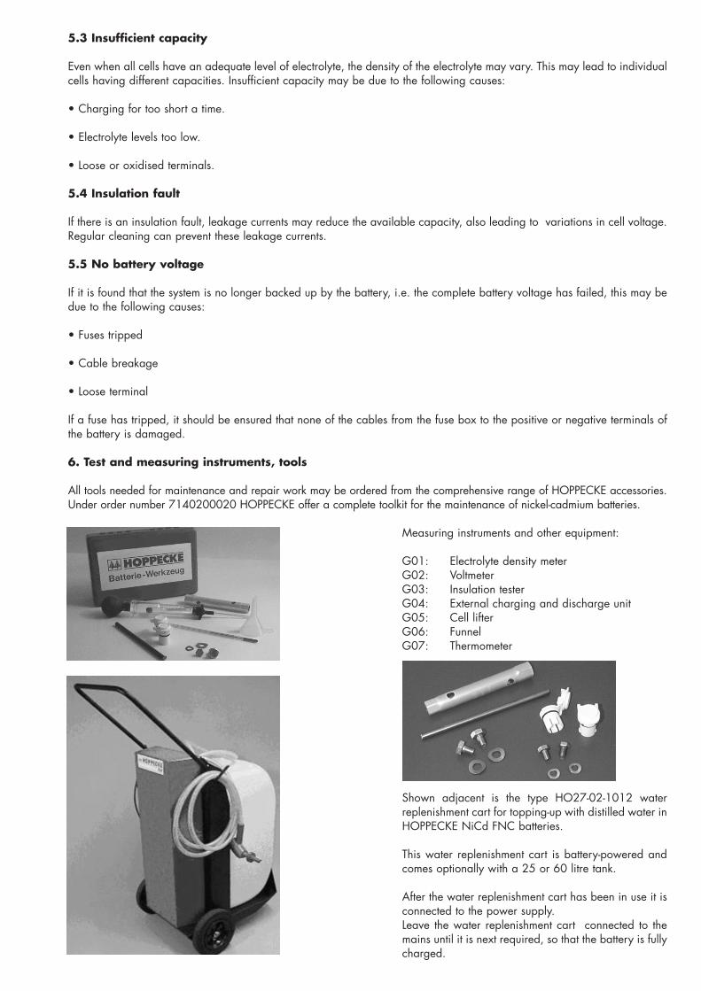
5.3 Insufficient capacity
Even when all cells have an adequate level of electrolyte, the density of the electrolyte may vary. This may lead to individualcells having different capacities. Insufficient capacity may be due to the following causes:
• Charging for too short a time.
• Electrolyte levels too low.
• Loose or oxidised terminals.
5.4 Insulation fault
If there is an insulation fault, leakage currents may reduce the available capacity, also leading to variations in cell voltage.Regular cleaning can prevent these leakage currents.
5.5 No battery voltage
If it is found that the system is no longer backed up by the battery, i.e. the complete battery voltage has failed, this may bedue to the following causes:
• Fuses tripped
• Cable breakage
• Loose terminal
If a fuse has tripped, it should be ensured that none of the cables from the fuse box to the positive or negative terminals ofthe battery is damaged.
6. Test and measuring instruments, tools
All tools needed for maintenance and repair work may be ordered from the comprehensive range of HOPPECKE accessories.Under order number 7140200020 HOPPECKE offer a complete toolkit for the maintenance of nickel-cadmium batteries.
Measuring instruments and other equipment:
G01: Electrolyte density meterG02: VoltmeterG03: Insulation testerG04: External charging and discharge unitG05: Cell lifterG06: FunnelG07: Thermometer
Shown adjacent is the type HO27-02-1012 waterreplenishment cart for topping-up with distilled water inHOPPECKE NiCd FNC batteries.
This water replenishment cart is battery-powered andcomes optionally with a 25 or 60 litre tank.
After the water replenishment cart has been in use it isconnected to the power supply.Leave the water replenishment cart connected to themains until it is next required, so that the battery is fullycharged.
spatel
Typewritten Text
C135676 REV A 04APR14
spatel
Typewritten Text
spatel
Typewritten Text
(25 of 26)
7. Taking the battery out of service
• Discharge at rated current I5 down to a voltage of 1.0 V per cell.
• Replace the standard vent plugs (hinged lid vent plugs) or AquaGen® vent plugs by the yellow transport plugs. This isimportant to avoid atmospheric oxygen coming into contact with the electrodes.
• Clean the battery including all cells
• Store on pallets in a dry, frost-free room. The complete battery or the individual cells should be provided with a cover.
In principle, when taking the battery out of service, the standard vent plugs (hinged lid vent plugs) or AquaGen� vent plugson the individual cells should be replaced by the yellow transport plugs. The standard vent plugs (hinged lid vent plugs) orAquaGen� vent plugs should be kept for subsequent use.
Depending on the length of storage after being taken out of service, the battery should be brought back into service againin accordance with these instructions.
7.1 Disposal
Disassembly and disposal of the battery should be carried out only by trained personnel. EC Directives 91156 (EEC) and9386 (EEC) must be observed. Your local HOPPECKE representative will be pleased to give you a quotation for proper disas-sembly and disposal of your battery. The long-term objective of the Hoppecke recycling concept is that all NiCd cells bro-ught into use are returned for proper recycling. HOPPECKE have a European-wide network of collection points for spentNiCd batteries. The benefit of the Hoppecke recycling concept is that the cadmium content of the batteries is recycled foruse in the production of new NiCd batteries. The recycled cadmium is thus continually reused in a “closed loop”.
Further action, in particular the operation and maintenance of the battery, is described in the instructions “Operationand maintenance of stationary nickel-cadmium batteries with FNC cells”. It is essential that these instructions, whichare supplied with the battery, are followed.
Used batteries with this symbol are recyclable goods and must be sent for recycling.Used batteries which are not sent for recycling are to be disposed of as special waste under the appropriate regu-lations. HOPPECKE have a “closed loop” recycling system for NiCd batteries. Your local HOPPECKE representati-ve will be pleased to give you a quotation for disposal of your battery.
HOPPECKE Batterie Systeme GmbHP.O.Box 11 40D-59914 Brilon (Hoppecke)
Phone (0 29 61) 97 06-2 12 · Fax 97 06-2 51http://www.hoppecke.dee-Mail: [email protected]
Cd
spatel
Typewritten Text
C135676 REV A 04APR14
spatel
Typewritten Text
(26 of 26)
spatel
Typewritten Text
DPenter
Text Box