Batch Pumping – A New Method to Solve Downhole Liquid Holdup Bill Elmer 2005 Beam Pumping...
23
Batch Pumping – A New Method to Solve Downhole Liquid Holdup Bill Elmer 2005 Beam Pumping Workshop
-
Upload
martha-bishop -
Category
Documents
-
view
217 -
download
0
Transcript of Batch Pumping – A New Method to Solve Downhole Liquid Holdup Bill Elmer 2005 Beam Pumping...

Batch Pumping – A New Method to Solve Downhole
Liquid Holdup
Bill Elmer
2005 Beam Pumping Workshop

Batch Pumping for Rod Pumped Gas Wells
Gas flows from casing annulus Liquid is pumped up tubing Some fluids rise with gas due to ineffective
gas / liquid separation in small diameter casing

Identifying and Solving Liquid Holdup
• Problem: Casing and liner sizes smaller than 5-1/2” have an annular area that is too small for effective downhole separation of gas and liquids.

Identifying and Solving Liquid Holdup
• Problem: Casing and liner sizes smaller than 5-1/2” have an annular area that is too small for effective downhole separation of gas and liquids.
• What is happening?– Fluid is prevented by turbulence around perforations
from falling– Cross-Sectional area too small to effect separation– Gas velocity not high enough to lift fluids, but will drag
fluid

Identifying and Solving Liquid Holdup
• How to Identify?
– Wells pumping at 15% or less– Wells that initially responded well to rod pumping, but
dropped off over a period of several days– Wells that are erratic producers– Wells producing at rates greater than 40% of Coleman

Identifying and Solving Liquid Holdup
• Test to see if it is a problem
– Note length of normal pumping cycle– Prior to start of pumping cycle, manually shut-in casing
for 10 minutes. Time length of this pumping cycle– Note if normal pumping time changes appreciably, you
have holdup– Open casing valve when pumpoff completed

How to Solve Liquid Holdup
• Install automated valve to perform this process– Pneumatic or electric powered of sufficient diameter– Give consideration for POC makers to add this ability
to product, as well as the sale of actuated ball valves and solenoid for gas operated motor valves

How to Solve Liquid Holdup
• Install automated valve to perform this process– Pneumatic or electric powered of sufficient diameter– Give consideration for POC makers to add this ability
to product, as well as the sale of actuated ball valves and solenoid for gas operated motor valves
• Field experience in East Texas suggests shut-in times of 6 to 8 minutes prior to starting pumping unit.
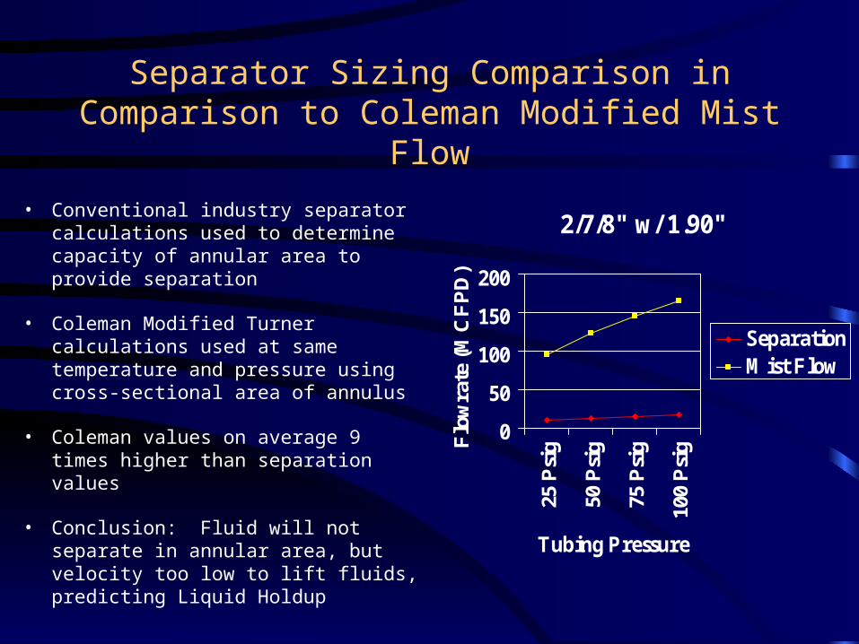
Separator Sizing Comparison in Comparison to Coleman Modified Mist Flow
• Conventional industry separator calculations used to determine capacity of annular area to provide separation
• Coleman Modified Turner calculations used at same temperature and pressure using cross-sectional area of annulus
• Coleman values on average 9 times higher than separation values
• Conclusion: Fluid will not separate in annular area, but velocity too low to lift fluids, predicting Liquid Holdup
2/7/8" w/ 1.90"
0
50
100
150
200
25 P
sig
50 P
sig
75 P
sig
100
Psi
g
Tubing Pressure
Flo
wra
te (
MC
FP
D)
SeparationMist Flow

Separator Sizing Comparison in Comparison to Coleman Modified Mist Flow
• Conventional industry separator calculations used to determine capacity of annular area to provide separation
• Coleman Modified Turner calculations used at same temperature and pressure using cross-sectional area of annulus
• Coleman values on average 9 times higher than separation values
• Conclusion: Fluid will not separate in annular area, but velocity too low to lift fluids, predicting Liquid Holdup
3-1/2" w/ 2-1/16"
050
100150200250300350
Tubing Pressure
Flo
wra
te (
MC
FP
D)
SeparationMist Flow

Separator Sizing Comparison in Comparison to Coleman Modified Mist Flow
• Conventional industry separator calculations used to determine capacity of annular area to provide separation
• Coleman Modified Turner calculations used at same temperature and pressure using cross-sectional area of annulus
• Coleman values on average 9 times higher than separation values
• Conclusion: Fluid will not separate in annular area, but velocity too low to lift fluids, predicting Liquid Holdup
4-1/2" w/ 2-3/8"
0200
400600
8001000
Tubing Pressure
Flo
wra
te (
MC
FP
D)
SeparationMist Flow

Separator Sizing Comparison in Comparison to Coleman Modified Mist Flow
• Conventional industry separator calculations used to determine capacity of annular area to provide separation
• Coleman Modified Turner calculations used at same temperature and pressure using cross-sectional area of annulus
• Coleman values on average 9 times higher than separation values
• Conclusion: Separation capacity between 90 and 140 MCFPD, and may be adequate.
5-1/2" w/ 2-3/8"
0200400600800
1000120014001600
Tubing Pressure
Flo
wra
te (
MC
FP
D)
SeparationMist Flow

Pirkle C-2
10
100
1000
4/1
/20
00
5/1
/20
00
6/1
/20
00
7/1
/20
00
8/1
/20
00
9/1
/20
00
10
/1/2
00
0
11
/1/2
00
0
12
/1/2
00
0
1/1
/20
01
2/1
/20
01
3/1
/20
01
4/1
/20
01
5/1
/20
01
6/1
/20
01
7/1
/20
01
8/1
/20
01
MC
FP
D
MCFPD

Daniels Gas Unit #3
10
100
1000
4/1
/20
00
5/1
/20
00
6/1
/20
00
7/1
/20
00
8/1
/20
00
9/1
/20
00
10
/1/2
00
0
11
/1/2
00
0
12
/1/2
00
0
1/1
/20
01
2/1
/20
01
3/1
/20
01
4/1
/20
01
5/1
/20
01
6/1
/20
01
7/1
/20
01
8/1
/20
01
MC
FPD
MCFPD

Clark C-2
10
100
1000
5/2
4/2
00
0
6/7
/20
00
6/2
1/2
00
0
7/5
/20
00
7/1
9/2
00
0
8/2
/20
00
8/1
6/2
00
0
8/3
0/2
00
0
9/1
3/2
00
0
9/2
7/2
00
0
10
/11
/20
00
10
/25
/20
00
11
/8/2
00
0
11
/22
/20
00
12
/6/2
00
0
12
/20
/20
00
1/3
/20
01
1/1
7/2
00
1
1/3
1/2
00
1
2/1
4/2
00
1
2/2
8/2
00
1
3/1
4/2
00
1
3/2
8/2
00
1
4/1
1/2
00
1
4/2
5/2
00
1
5/9
/20
01
5/2
3/2
00
1
6/6
/20
01
6/2
0/2
00
1
7/4
/20
01
7/1
8/2
00
1
8/1
/20
01
8/1
5/2
00
1
MCFPD
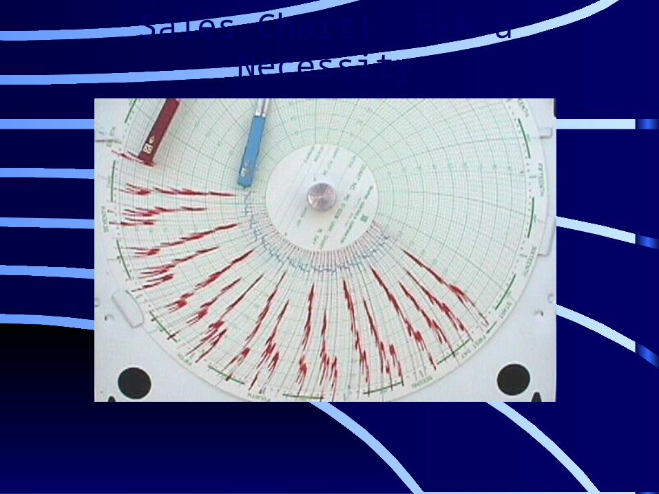
Sales Chart! EFM a Necessity

Application for wells with 2-7/8” Casing
• Previous slides were wells with liners
• What about 2-7/8” Casing?
• EOG has installed three pumping units – Two are very new, and are pumping well– First one installed in late 2001 on CGU 108

Application for wells with 2-7/8” Casing
CGU 108 comprised of multiple depleted Travis Peak sands (aka Hosston) in Panola County, TX– Multiple composite bridgeplugs drilled out– J-55 tubing run to bottom without tubing anchor– 1.06” pump run on 5/8” Grade D rods with slimhole
boxes to 7000’– Conventional 160 pumping unit installed with Pumpoff
controller

CGU 108
2-7/8” Casing

Application for wells with 2-7/8” Casing
• CGU 108 Application was abandoned in 2003 – J-55 tubing parted below boxes when backing off stuck
rods– N-80 tubing was really required at this depth– Paraffin was a problem, and we did not have guides– New gas lift lines were installed nearby, with plans to
install gas lift valves in future

Opportunities to Improve Batch Pumping Concept
• Increase flow period by opening casing valve before pumpoff occurs– Like plunger lift, a goal is to maximize flow time– If adequate rathole exits below perforations, valve can
be opened whenever majority of fluid has fallen past perforations
Opportunities to Improve Batch Pumping Concept
• Increase flow period by opening casing valve before pumpoff occurs– Like plunger lift, a goal is to maximize flow time– If adequate rathole exits below perforations, valve can
be opened whenever majority of fluid has fallen past perforations
• How long does it take for the fluid to fall past the perforations?– A good topic for another meeting