Instruction Manual, Minelab XChange 2 User Manual Russian Language web4901 0135-2
description
Open-File Report 01–135Version 1.0 2001
U.S. Department of the InteriorU.S. Geological Survey
Basin-Centered Gas Systems of the U.S.By Marin A. Popov,1 Vito F. Nuccio,2 Thaddeus S. Dyman,2 Timothy A. Gognat,1 Ronald C. Johnson,2 James W. Schmoker,2 Michael S. Wilson,1 and Charles Bartberger1
Appalachian Basin(Clinton–Medinaand older Fms)
Michigan Basin(St. Peter Ss)
Mid-ContinentRift
ColumbiaBasin
Sweetgrass Arch
Snake RiverDownwarp
San Rafael Swell(Dakota Fm)
Wasatch Plateau
DenverBasin
Hanna BasinGreatBasin
ChuarGroup
ParkBasins
RatonBasin
Black WarriorBasin
AnadarkoBasin
ArkomaBasin
PermianBasin
(Abo Fm)
Western Washington(Willamette–Puget
Sound Trough)
SacramentoBasin
Santa Maria Basin(Monterey Fm)
Hornbrook Basin–Modoc Plateau
SaltonTrough
Los Angeles Basin
Rio Grande Rift(Albuquerque Basin)
Paradox Basin(Cane Creek interval)
Gulf Coast–Austin Chalk;
Eagle Fm
Gulf Coast–Travis Peak Fm–Cotton Valley Grp
Mesozoic RiftBasins
This report is preliminary, has not been reviewed for conformity with U. S. Geological Survey editorial standards and stratigraphic nomenclature, and should not be reproduced or distributed. Any use of trade names is for descriptive purposes only and does not imply endorsement by theU. S. Government.
Colville Basin
CentralAlaskaBasins
Cook Inlet
1Geologic consultants on contract to the USGS2USGS, Denver
BASIN-CENTERED GAS SYSTEMS OF THE U.S.DE-AT26-98FT40031
U.S. Department of Energy, National Energy Technology LaboratoryContractor: U.S. Geological Survey Central Region Energy Team
DOE Project Chief: Bill GwilliamUSGS Project Chief: V.F. Nuccio
Contract Period: April, 1998-November, 2000
Final Report
iii
TABLE OF CONTENTS
I n t r o d u c t i o n . . . . . . . . . . . . . . . . . . . . . . . . . . . . . . . . . . . . . . . . . . . . . . . . . . . . . . . . . . . . . . . . . . . . . . . . 5P h a s e I . . . . . . . . . . . . . . . . . . . . . . . . . . . . . . . . . . . . . . . . . . . . . . . . . . . . . . . . . . . . . . . . . . . . . . . . . . . . . . . 6
L i s t o f High Potent ia l Accumula t ions . . . . . . . . . . . . . . . . . . . . . . . . . . . . . . . . . . . . 6List of Other Potential Accumulations . . . . . . . . . . . . . . . . . . . . . . . . . . . . . . . . . . . 6
P h a s e I I . . . . . . . . . . . . . . . . . . . . . . . . . . . . . . . . . . . . . . . . . . . . . . . . . . . . . . . . . . . . . . . . . . . . . . . . . . . . . . 7Basin-centered/continuous-type accumulat ions. . . . . . . . . . . . . . . . . . . . . . . . . . . . . . .8
Examples of pressure condition variabil ity in gas deposits. . . . . . . . . . .9Hanna Basin . . . . . . . . . . . . . . . . . . . . . . . . . . . . . . . . . . . . . . . . . . . . . . . . . . . . . . . . . . . . . . . 9Applachian Basin (Cl inton-Medina Fms) . . . . . . . . . . . . . . . . . . . . . . . . . . . .10Gulf Coast Basin-Cotton Valley Group . . . . . . . . . . . . . . . . . . . . . . . . . . . . . 1 0
P r o j e c t O r g a n i z a t i o n . . . . . . . . . . . . . . . . . . . . . . . . . . . . . . . . . . . . . . . . . . . . . . . . . . . . . . . . . . . . 1 1Acknowledgements . . . . . . . . . . . . . . . . . . . . . . . . . . . . . . . . . . . . . . . . . . . . . . . . . . . . . . . . . . . . . . 1 2
PHASE I
A n a d a r k o B a s i n . . . . . . . . . . . . . . . . . . . . . . . . . . . . . . . . . . . . . . . . . . . . . . . . . . . . . . . . . . . . . . . . . . . 1 4Appalachian Basin (Clinton/Medina and Older Formations).. . . . . . . . . . . . 21Arkoma Basin . . . . . . . . . . . . . . . . . . . . . . . . . . . . . . . . . . . . . . . . . . . . . . . . . . . . . . . . . . . . . . . . . . . . 2 9B l a c k W a r r i o r B a s i n . . . . . . . . . . . . . . . . . . . . . . . . . . . . . . . . . . . . . . . . . . . . . . . . . . . . . . . . . . . . . 3 7Central Alaska Basins . . . . . . . . . . . . . . . . . . . . . . . . . . . . . . . . . . . . . . . . . . . . . . . . . . . . . . . . . . 4 5Chuar Group (Precambrian Paradox Basin). . . . . . . . . . . . . . . . . . . . . . . . . . . . . . . . . . 53C o l u m b i a B a s i n . . . . . . . . . . . . . . . . . . . . . . . . . . . . . . . . . . . . . . . . . . . . . . . . . . . . . . . . . . . . . . . . . . 5 8Colville Basin, Alaska . . . . . . . . . . . . . . . . . . . . . . . . . . . . . . . . . . . . . . . . . . . . . . . . . . . . . . . . . . 6 4C o o k I n l e t , A l a s k a . . . . . . . . . . . . . . . . . . . . . . . . . . . . . . . . . . . . . . . . . . . . . . . . . . . . . . . . . . . . . . 7 7Denver Basin . . . . . . . . . . . . . . . . . . . . . . . . . . . . . . . . . . . . . . . . . . . . . . . . . . . . . . . . . . . . . . . . . . . . . 8 5Great Bas in (Tert iary Bas ins ) . . . . . . . . . . . . . . . . . . . . . . . . . . . . . . . . . . . . . . . . . . . . . . . . . . 95G u l f C o a s t - A u s t i n C h a l k . . . . . . . . . . . . . . . . . . . . . . . . . . . . . . . . . . . . . . . . . . . . . . . . . . . . . 1 0 4Gul f Coas t -Eag le Ford Format ion . . . . . . . . . . . . . . . . . . . . . . . . . . . . . . . . . . . . . . . . . . 111Gulf Coast-Travis Peak/Cotton Val ley Formations . . . . . . . . . . . . . . . . . . . . . 118Hanna Basin . . . . . . . . . . . . . . . . . . . . . . . . . . . . . . . . . . . . . . . . . . . . . . . . . . . . . . . . . . . . . . . . . . . . 1 2 5Hornbrook Format ion/Modoc Plateau. . . . . . . . . . . . . . . . . . . . . . . . . . . . . . . . . . . . . . .133L o s A n g e l e s B a s i n . . . . . . . . . . . . . . . . . . . . . . . . . . . . . . . . . . . . . . . . . . . . . . . . . . . . . . . . . . . . . 1 4 1Mesozoic Rift Basins (Eastern U.S.) . . . . . . . . . . . . . . . . . . . . . . . . . . . . . . . . . . . . . . . 1 4 8Michigan Bas in (S t . Pe ter Sandstone) . . . . . . . . . . . . . . . . . . . . . . . . . . . . . . . . . . . . . 155M i d - C o n t i n e n t R i f t . . . . . . . . . . . . . . . . . . . . . . . . . . . . . . . . . . . . . . . . . . . . . . . . . . . . . . . . . . . . 1 6 4Paradox Bas in (Cane Creek Interval ) . . . . . . . . . . . . . . . . . . . . . . . . . . . . . . . . . . . . . . . 171P a r k B a s i n s o f C o l o r a d o . . . . . . . . . . . . . . . . . . . . . . . . . . . . . . . . . . . . . . . . . . . . . . . . . . . . . . 1 7 9Permian Bas in (Abo Format ion) . . . . . . . . . . . . . . . . . . . . . . . . . . . . . . . . . . . . . . . . . . . . 187R a t o n B a s i n . . . . . . . . . . . . . . . . . . . . . . . . . . . . . . . . . . . . . . . . . . . . . . . . . . . . . . . . . . . . . . . . . . . . . 1 9 5Rio Grande Rif t (Albuquerque Bas in) . . . . . . . . . . . . . . . . . . . . . . . . . . . . . . . . . . . . . . 203S a c r a m e n t o B a s i n . . . . . . . . . . . . . . . . . . . . . . . . . . . . . . . . . . . . . . . . . . . . . . . . . . . . . . . . . . . . . . 2 1 2Salton Trough, California . . . . . . . . . . . . . . . . . . . . . . . . . . . . . . . . . . . . . . . . . . . . . . . . . . . 2 1 9San Rafae l Swe l l (Dakota Format ion) . . . . . . . . . . . . . . . . . . . . . . . . . . . . . . . . . . . . . 227S a n t a M a r i a B a s i n . . . . . . . . . . . . . . . . . . . . . . . . . . . . . . . . . . . . . . . . . . . . . . . . . . . . . . . . . . . . . 2 3 5Snake River Downwarp, Idaho . . . . . . . . . . . . . . . . . . . . . . . . . . . . . . . . . . . . . . . . . . . . . . 2 4 2Sweetgrass Arch (Centra l Montana) . . . . . . . . . . . . . . . . . . . . . . . . . . . . . . . . . . . . . . . . 250W a s a t c h P l a t e a u . . . . . . . . . . . . . . . . . . . . . . . . . . . . . . . . . . . . . . . . . . . . . . . . . . . . . . . . . . . . . . . . 2 5 7Western Washington (Willamette-Puget Sound Trough). . . . . . . . . . . . . . . . 264
iv
R e f e r e n c e s C i t e d . . . . . . . . . . . . . . . . . . . . . . . . . . . . . . . . . . . . . . . . . . . . . . . . . . . . . . . . . . . . . . . 2 7 0S e l e c t e d B i b l i o g r a p h y . . . . . . . . . . . . . . . . . . . . . . . . . . . . . . . . . . . . . . . . . . . . . . . . . . . . . . . . . 2 9 0
Appendix I: Phase II Abstracts
Potential for a basin-center gas accumulation in the AlbuquerqueB a s i n , N e w M e x i c o . . . . . . . . . . . . . . . . . . . . . . . . . . . . . . . . . . . . . . . . . . . . . . . . . . . . 2 9 4
Is there a basin-center gas accumulation in the deep AnadarkoB a s i n ? . . . . . . . . . . . . . . . . . . . . . . . . . . . . . . . . . . . . . . . . . . . . . . . . . . . . . . . . . . . . . . . . . . . . 2 9 4
Is there a basin-center gas accumulation in the Columbia BasinPasco Bas in) , Centra l Washington? . . . . . . . . . . . . . . . . . . . . . . . . . . . . . . . . 295
Is there a basin-center gas accumulation in the Cotton ValleyGroup Sandstones, Gulf Coast Basin, USA? . . . . . . . . . . . . . . . . . . . . . 2 9 5
Is there a basin-center gas accumulation in the Ordovician-AgeGlenwood Formation and St Peter Sandstone, CentralM i c h i g a n B a s i n ? . . . . . . . . . . . . . . . . . . . . . . . . . . . . . . . . . . . . . . . . . . . . . . . . . . . . . . . 2 9 6
Potential for a basin-center gas accumulation in the RatonBas in , Colorado and New Mexico . . . . . . . . . . . . . . . . . . . . . . . . . . . . . . . . . . . 296
Does the Forbes Formation in the Sacramento Basin contain abasin-center gas accumulation? . . . . . . . . . . . . . . . . . . . . . . . . . . . . . . . . . . . . . 2 9 7
Is there a basin-center gas accumulation in the Travis Peak(Hosston) Formation, Gulf Coast Basin, USA?. . . . . . . . . . . . . . . . . .298
5
INTRODUCTION
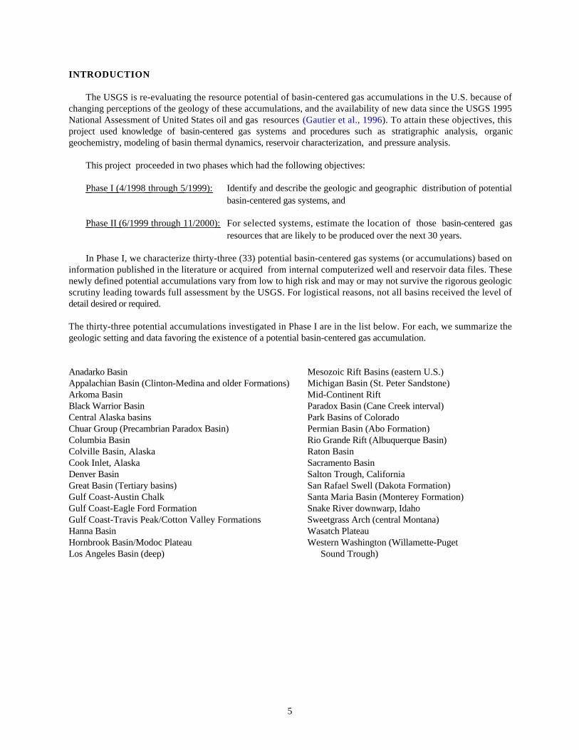
The USGS is re-evaluating the resource potential of basin-centered gas accumulations in the U.S. because ofchanging perceptions of the geology of these accumulations, and the availability of new data since the USGS 1995National Assessment of United States oil and gas resources (Gautier et al., 1996). To attain these objectives, thisproject used knowledge of basin-centered gas systems and procedures such as stratigraphic analysis, organicgeochemistry, modeling of basin thermal dynamics, reservoir characterization, and pressure analysis.
This project proceeded in two phases which had the following objectives:
Phase I (4/1998 through 5/1999): Identify and describe the geologic and geographic distribution of potentialbasin-centered gas systems, and
Phase II (6/1999 through 11/2000): For selected systems, estimate the location of those basin-centered gasresources that are likely to be produced over the next 30 years.
In Phase I, we characterize thirty-three (33) potential basin-centered gas systems (or accumulations) based oninformation published in the literature or acquired from internal computerized well and reservoir data files. Thesenewly defined potential accumulations vary from low to high risk and may or may not survive the rigorous geologicscrutiny leading towards full assessment by the USGS. For logistical reasons, not all basins received the level ofdetail desired or required.
The thirty-three potential accumulations investigated in Phase I are in the list below. For each, we summarize thegeologic setting and data favoring the existence of a potential basin-centered gas accumulation.
Anadarko Basin Mesozoic Rift Basins (eastern U.S.)Appalachian Basin (Clinton-Medina and older Formations) Michigan Basin (St. Peter Sandstone)Arkoma Basin Mid-Continent RiftBlack Warrior Basin Paradox Basin (Cane Creek interval)Central Alaska basins Park Basins of ColoradoChuar Group (Precambrian Paradox Basin) Permian Basin (Abo Formation)Columbia Basin Rio Grande Rift (Albuquerque Basin)Colville Basin, Alaska Raton BasinCook Inlet, Alaska Sacramento BasinDenver Basin Salton Trough, CaliforniaGreat Basin (Tertiary basins) San Rafael Swell (Dakota Formation)Gulf Coast-Austin Chalk Santa Maria Basin (Monterey Formation)Gulf Coast-Eagle Ford Formation Snake River downwarp, IdahoGulf Coast-Travis Peak/Cotton Valley Formations Sweetgrass Arch (central Montana)Hanna Basin Wasatch PlateauHornbrook Basin/Modoc Plateau Western Washington (Willamette-PugetLos Angeles Basin (deep) Sound Trough)
6
PHASE I
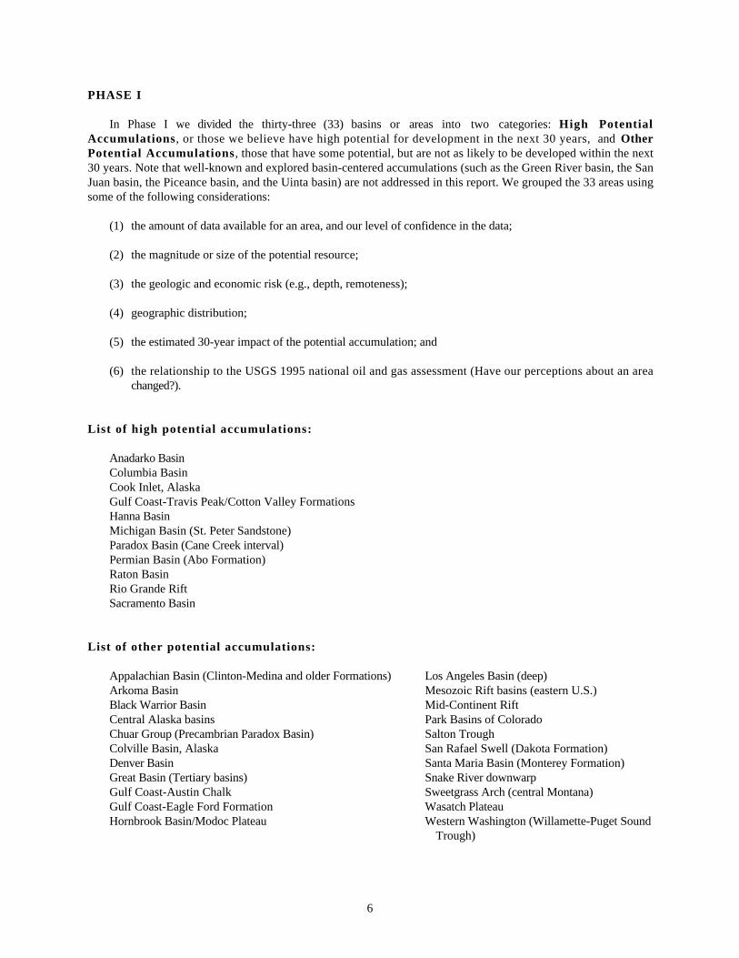
In Phase I we divided the thirty-three (33) basins or areas into two categories: High PotentialAccumulations, or those we believe have high potential for development in the next 30 years, and OtherPotential Accumulations , those that have some potential, but are not as likely to be developed within the next30 years. Note that well-known and explored basin-centered accumulations (such as the Green River basin, the SanJuan basin, the Piceance basin, and the Uinta basin) are not addressed in this report. We grouped the 33 areas usingsome of the following considerations:
(1) the amount of data available for an area, and our level of confidence in the data;
(2) the magnitude or size of the potential resource;
(3) the geologic and economic risk (e.g., depth, remoteness);
(4) geographic distribution;
(5) the estimated 30-year impact of the potential accumulation; and
(6) the relationship to the USGS 1995 national oil and gas assessment (Have our perceptions about an areachanged?).
List of high potential accumulations:
Anadarko BasinColumbia BasinCook Inlet, AlaskaGulf Coast-Travis Peak/Cotton Valley FormationsHanna BasinMichigan Basin (St. Peter Sandstone)Paradox Basin (Cane Creek interval)Permian Basin (Abo Formation)Raton BasinRio Grande RiftSacramento Basin
List of other potential accumulations:
Appalachian Basin (Clinton-Medina and older Formations) Los Angeles Basin (deep)Arkoma Basin Mesozoic Rift basins (eastern U.S.)Black Warrior Basin Mid-Continent RiftCentral Alaska basins Park Basins of ColoradoChuar Group (Precambrian Paradox Basin) Salton TroughColville Basin, Alaska San Rafael Swell (Dakota Formation)Denver Basin Santa Maria Basin (Monterey Formation)Great Basin (Tertiary basins) Snake River downwarpGulf Coast-Austin Chalk Sweetgrass Arch (central Montana)Gulf Coast-Eagle Ford Formation Wasatch PlateauHornbrook Basin/Modoc Plateau Western Washington (Willamette-Puget Sound
Trough)

7
PHASE II
In Phase II we made a much more comprehensive analysis of seven of the eleven high potential areas fromPhase I determined to contain resources that will be available in a 30-year period. These areas include the following:
Anadarko BasinColumbia BasinGulf Coast-Travis Peak/Cotton Valley (two reports presented separately)Michigan Basin (St. Peter Sandstone)Raton BasinRio Grande Rift (Albuquerque Basin)Sacramento Basin
Extensive research and analysis on each of the seven areas resulted in interpretive reports that will be released asseparate chapters in U.S.G.S. E-Bulletin Series 2184. The U.S. Geological Survey’s publication policy states thatinterpretive research cannot be published as an Open-File Report; therefore, the eight reports, now in press, will bepublished as Electronic Bulletins and will be available via the Internet at:
http://greenwood.cr.usgs.gov/bulletin.html
The titles and abstracts for each of the eight bulletin chapters follow in Appendix I: Phase II Abstracts.
8
BASIN-CENTERED/CONTINUOUS-TYPE ACCUMULATIONS
Basin-centered or continuous-type accumulations are large single fields having spatial dimensions equal to orexceeding those of conventional plays. They cannot be represented in terms of discrete, countable units delineated bydowndip hydrocarbon-water contacts (as are conventional fields). The definition of continuous accumulations is basedon geology rather than on government regulations defining low permeability (tight) gas. Continuous accumulationsare identified by their occurrence downdip from water-saturated rocks, lack of obvious trap or seal, relatively lowmatrix permeability, abnormal (either high or low) pressures, large in-place hydrocarbon volumes, and low recoveryfactors (Schmoker, 1995). There may be a period of normal pressuring during the transition between over- andunderpressuring. This period can occur when a basin experiences uplift and erosion, causing basin cooling.
The U.S. Geological Survey 1995 National Petroleum Assessment treated continuous plays as a separatecategory, and play assessment used a specialized methodology (Schmoker, 1995). Continuous plays are geologicallydiverse and include the following categories: coal-bed gas, some biogenic gas occurrences, fractured gas shales, andbasin-centered natural gas accumulations. Only continuous-type basin-centered gas plays comprise significant futureundiscovered resources in deep sedimentary basins.
Assessment of continuous plays is based on the concept that an accumulation can be regarded as a collection ofhydrocarbon-bearing cells. In the play, cells represent spatial subdivisions defined by the drainage area of wells.Cells may be productive, nonproductive, or untested. Geologic risk, expressed as play probability, is assigned toeach play. The number of untested cells in a play, and the fraction of untested cells expected to become productive(success ratio) are estimated, and a probability distribution is defined for estimated ultimate recoveries (EURs) forthose cells expected to become productive. The combination of play probability, success ratio, number of untestedcells, and EUR probability distribution yields potential undiscovered resources for each play. Refer to Schmoker(1995) for a detailed discussion of continuous-type plays and their assessment.
In 1995 the USGS defined 61 continuous-type plays with oil and gas reservoirs in sandstones, shales, chalks,and coals. Of the 61 identified plays, 47 were assessed, of which 34 were gas plays. Estimates of technicallyrecoverable gas resources from continuous-type sandstones, shales, and chalks range from 219 Tcf (95th fractile) to417 Tcf (5th fractile), with a mean estimate of 308 Tcf. Continuous-type accumulations were not assessed oridentified in many areas or regions of the U.S.
Four categories of continuous-type accumulations can be identified with respect to new data and perceptionssince the USGS 1995 National Petroleum Assessment:
(1) Continuous-type plays that were correctly identified as such, assessed in 1995, but need to be updatedbecause of new data;
(2) Continuous-type plays that may have been identified incorrectly as conventional plays and assessed as suchin 1995;
(3) Continuous-type plays that were identified as such in 1995, but not assessed because of a lack of data; and
(4) New continuous-type plays that were not identified in 1995.
In detail, basin-centered gas accumulations have the following characteristics:
(1) They are geographically large and cover from 10s to 100s of square miles in areal extent, often occupyingthe central deeper parts of sedimentary basins;
(2) They lack downdip water contacts, and hydrocarbons are not held in place by gas floating above water;
(3) Reservoirs are abnormally pressured, either under- or overpressured;
9
(4) The pressuring phase of the reservoir is maintained by gas;
(5) Water production is usually low or absent;
(6) Most reservoir permeability is low, generally less than 0.1 md;
(7) Reservoirs may be overlain by normally pressured rock;
(8) Reservoirs contain primarily thermogenic gas, although some shallow basin-centered reservoirs containinggas of biologic origin occur in somewhat different geologic environments;
(9) Source rocks are in close proximity to reservoir rocks;
(10)Structural and stratigraphic traps are less important; compartments may exist and can generally form anarray of accumulation “sweet spots;”
(11)Multiple fluid phases contribute to seal development in reservoirs; and
(12)The tops of many basin-centered accumulations occur within a narrow range of vitrinite reflectance, usuallybetween 0.75 and 0.9 Ro.
Examples of pressure condition variability in gas deposits
A distinction needs to be made between low-permeability (tight) conventional accumulations, which may ormay not be abnormally pressured, and continuous basin-center accumulations that are, by definition, abnormallypressured. If only limited geologic and production data are available, erroneous interpretations may result. Thefollowing examples from the Phase II interpretive reports (in press) illustrate the high variability in pressureconditions in gas deposits that may or may not be basin-centered accumulations.
Hanna Basin, Wyoming (a basin-centered continuous-type accumulation with both over- andunderpressured compartments)
A geologic and production data set based on 29 deep wells in the Hanna basin supports the presence of ahypothetical (no known production) basin-center gas play. The Hanna is a small, deep Laramide pull-apart basinlocated in south-central Wyoming.
Data interpretations suggest that both over- and underpressured compartments exist (Wilson et al., in press). Agas-charged overpressured interval may exist within the Cretaceous Mowry, Frontier and Niobrara Formations atdepths below 10,000 ft along the southern and western margins of the basin. Overpressuring may also occur near thebasin center within the Steele Shale and lower Mesaverde Group section at depths below 18,000 to 20,000 ft. Thisoverpressured zone is likely to be relatively small (probably 20 to 25 mi in diameter) and is probably depleted of gasnear major basement reverse faults and outcrops where gas may have escaped.
A zone of subnormal pressure also may exist below a shallow water-saturated, normally pressured zone, andabove the central zone of overpressure. Subnormal pressures may occur in the center of the Hanna basin at depthsranging from 10,000 to 25,000 feet based on indirect evidence that includes lost-circulation zones. On the south sideof the basin, where the top of the sub-normally pressured zone is believed to cut across stratigraphic boundaries, testsof the Niobrara Formation in three wells showed some gas and oil recovery with very low shut-in pressures.
10
Appalachian Basin (Clinton-Medina and Older Formations) (normal conventionalaccumulations and continuous-type underpressured basin-centered accumulations)
In the Appalachian basin, oil and gas trapped in Lower Silurian sandstone reservoirs define a regionalhydrocarbon accumulation covering large areas of Ohio, Pennsylvania, New York, and Ontario, Canada (Ryder andZagorski, 2000). Major reservoirs consist of Clinton and Medina Sandstones in Ohio, and Crimsby and WhirlpoolSandstones of the Medina Group in Pennsylvania and New York. These Lower Silurian sandstones were deposited asa regional clastic wedge in a foreland basin setting during the late phase of the Taconic orogeny. Using RockyMountain examples as a guide, the eastern gas-bearing part of the Lower Silurian regional accumulation isrecognized as a basin-center gas accumulation, whereas the western part is recognized as a conventionalaccumulation.
In Ohio and northwestern Pennsylvania, the boundary between accumulation types has been placed at the -3,500ft subsea structural contour on the top of the Clinton Sandstone (Ryder and Zagorski, 2000). East of this northeast-trending boundary, reservoirs are underpressured, gas-charged, and contain no producible water. Reservoirs west of theboundary, in the conventional part of the accumulation, have mobile formation water and are normally pressured.Here, the updip pinchout of the Lower Silurian clastic wedge stratigraphically traps conventional reservoirs. In theeastern basin-center gas accumulation, reservoirs are tight (less than 0.1 md), and have high irreducible watersaturations and abnormally low formation pressures.
Gulf Coast Basin–Cotton Valley Group (normal to overpressured conventional accumulations)
In 1995 the USGS assessed two conventional gas plays and one continuous basin-center gas play (CottonValley Blanket Sandstones Gas play ) in Cretaceous/Jurassic Cotton Valley sandstones of the onshore northern GulfCoast basin. Re-evaluation of geologic and production data on hundreds of wells suggests that all of these plays areconventional, and that a continuous basin-center gas accumulation does not exist in Cotton Valley sandstones(Bartberger et al., in press).
Using reservoir properties and gas-production characteristics, Bartberger and others (in press) identified twoCotton Valley sandstone trends: 1) transgressive blanket sandstones across northern Louisiana have relatively highporosity and permeability and do not require fracture stimulation to produce gas at commercial rates; and 2) south ofthis trend and extending westward into east Texas, massive sandstones of the Cotton Valley exhibit low porosity andpermeability and do require fracture stimulation. Pressure gradients throughout most of both trends are normal.
Two factors indicate that the fields in this trend are conventional: 1) the presence of gas-water contacts in at leastseven fields across the blanket-sandstone trend, and 2) the relatively high permeabilities and high gas-production ratesoccurring without fracture stimulation. Within the tight massive-sandstone trend, however, permeability issufficiently low that gas-water transition zones are vertically extensive and gas-water contacts are poorly defined.With increasing depth through these transition zones, gas saturation decreases and water saturation increases;eventually, gas saturations may become sufficiently low that, in terms of cumulative production, wells become non-commercial. The interpreted presence of gas-water contacts within the tight, massive Cotton Valley sandstone trendsuggests that accumulations in this trend are also conventional, and that a basin-center gas accumulation does notexist within the Cotton Valley Sandstone in the northern Gulf Basin.
11
PROJECT ORGANIZATION
TASKS:
Phase I (April 1998 through March 1999)The USGS shall conduct a National inventory of known basin-centered gas systems, define newpotential systems, rank them according to levels of geologic certainty, further delineate theirgeologic and geographic characteristics, and produce a map showing their distribution throughoutthe U.S.
Task No. 1 April 1998 through March 1999Conduct a National inventory of known basin-centered gas systems and produce a map showinggeographic location, and supporting documentation of their stratigraphic location and geologiccharacteristics.
Task No. 2 April 1998 through March 1999Re-examine basins and other areas throughout the U.S. that were previously defined asconventional accumulations, and determine if they might have been mis-classified. If it isdetermined that these basins or areas exhibit characteristics that could be consistent with those ofbasin-centered gas systems, maps of their location and supporting geologic documentation will beprovided.
Task No. 3 October 1998 through March 1999Risk and rank the newly created list of basin-centered gas systems according to levels of geologiccertainty.
Phase II (June 1999 through November 2000)Phase II focuses on defining “sweet spots” (that portion of the basin-centered gas resource that willbe available in 30 years) within the seven basin-centered gas systems determined in Phase I(Sacramento/San Joaquin Basins, Raton Basin, Rio Grande Rift, Anadarko Basin, TravisPeak/Cotton Valley, Columbia Basin/W. Flank of the Cascades, Michigan Basin/St. PeterSandstone).
Task No. 4 June 1999 through November 2000Through rigorous geologic analysis, define “sweet spots” within the selected basin-centered gassystems.
Task No. 5 June 1999 through November 2000For the “sweet spots”, make judgments and recommendations as to the 30-year availability of thegas resource.
Task No. 6 June 1999 through November 2000Prepare a final report that documents the Phase I and Phase II activities. The final report shallinclude a digital map showing all defined basin-centered gas systems for the U.S., documentationof their geologic characteristics, identification of selected potential sweet spots, and judgments andrecommendations as to the social relevance of the resource (availability over a 30-year time frame).
12
ACKNOWLEDGEMENTS
Various individuals contributed to project research, authoring and editing. The following list includes thecontributing authors and their respective basins:
T.A. Gognat
Anadarko BasinAppalachian Basin (Clinton-Medina and older Formations)Arkoma BasinCentral Alaska basinsColumbia BasinCook Inlet, AlaskaDenver BasinGulf Coast-Travis Peak/Cotton Valley FormationsMid-Continent RiftRaton BasinWestern Washington (Willamette-Puget Sound Trough)
R. Wells
San Rafael Swell (Dakota Formation)
J.C. Fiduk
Permian Basin (Abo Formation)
C. Carothers
Park Basins of Colorado
M.A. Heinrich
Colville Basin, AlaskaGreat Basin (Tertiary basins)Hornbrook Basin/Modoc PlateauSnake River downwarp
C. Marchand
Gulf Coast-Austin ChalkGulf Coast-Eagle Ford FormationSacramento BasinSweetgrass Arch (central Montana)
13
S.K. Nodelund
Anadarko BasinDenver BasinRaton Basin
A.M. Ochs
Chuar Group (Precambrian Paradox Basin)Michigan Basin (St. Peter Sandstone)Paradox Basin (Cane Creek interval)
K.M. Peterson
Rio Grande Rift (Albuquerque Basin)Wasatch Plateau
S.S. Shapurji
Central Alaska basinsGulf Coast-Travis Peak/Cotton Valley Formations
R. Tauman
Appalachian Basin (Clinton-Medina and older Formations)Black Warrior BasinHanna BasinLos Angeles Basin (deep)Mesozoic Rift Basins (eastern U.S.)
M.S. Wilson
Salton Trough, California
14
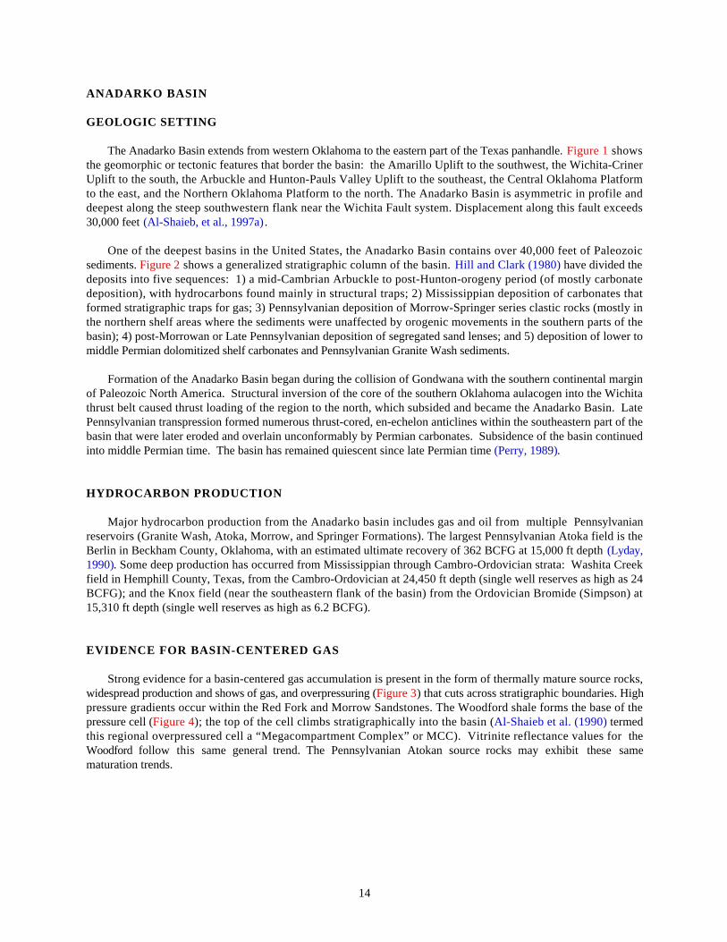
ANADARKO BASIN
GEOLOGIC SETTING
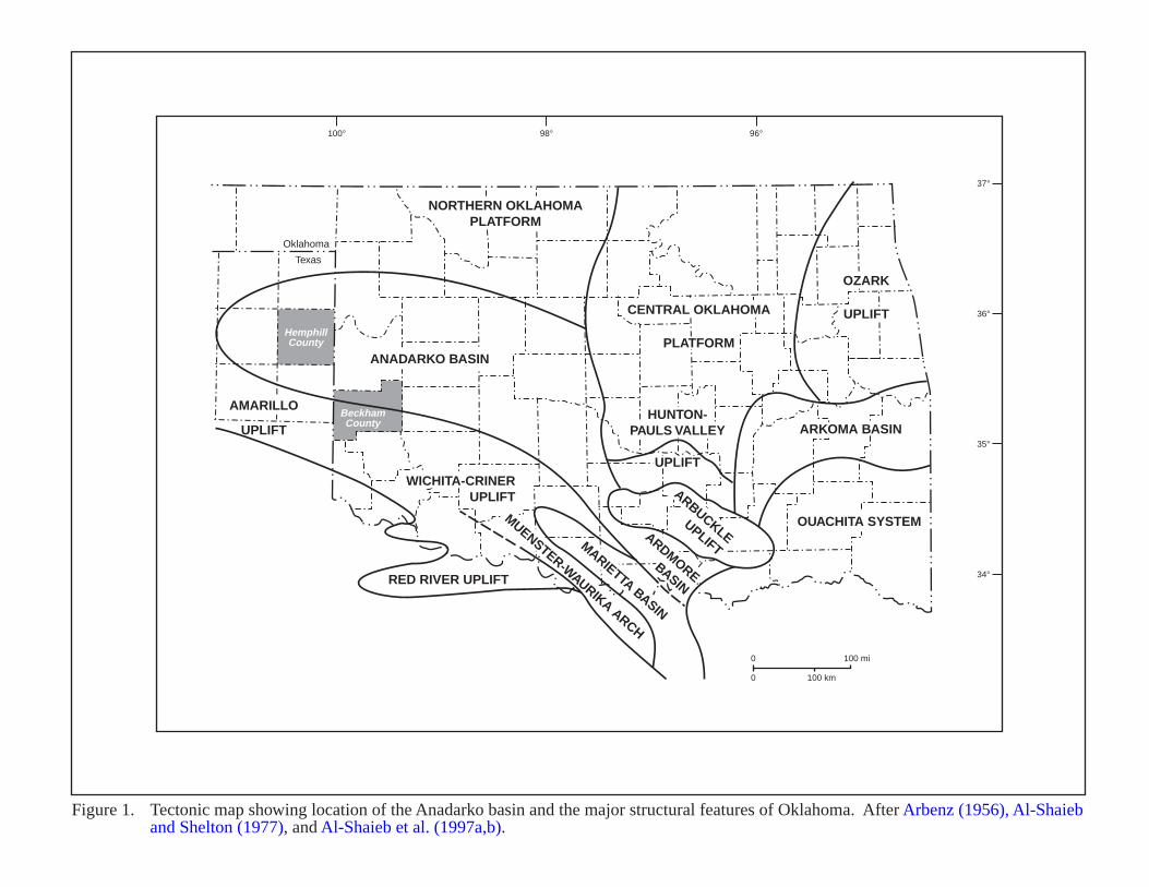
The Anadarko Basin extends from western Oklahoma to the eastern part of the Texas panhandle. Figure 1 showsthe geomorphic or tectonic features that border the basin: the Amarillo Uplift to the southwest, the Wichita-CrinerUplift to the south, the Arbuckle and Hunton-Pauls Valley Uplift to the southeast, the Central Oklahoma Platformto the east, and the Northern Oklahoma Platform to the north. The Anadarko Basin is asymmetric in profile anddeepest along the steep southwestern flank near the Wichita Fault system. Displacement along this fault exceeds30,000 feet (Al-Shaieb, et al., 1997a).
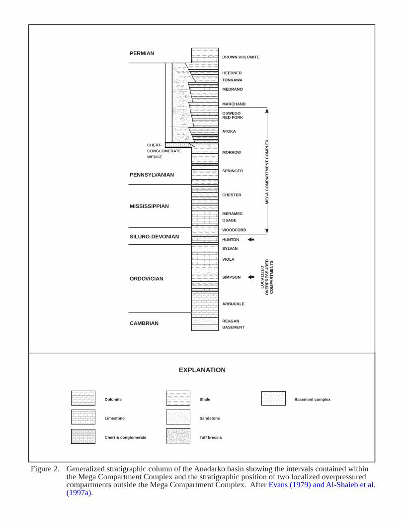
One of the deepest basins in the United States, the Anadarko Basin contains over 40,000 feet of Paleozoicsediments. Figure 2 shows a generalized stratigraphic column of the basin. Hill and Clark (1980) have divided thedeposits into five sequences: 1) a mid-Cambrian Arbuckle to post-Hunton-orogeny period (of mostly carbonatedeposition), with hydrocarbons found mainly in structural traps; 2) Mississippian deposition of carbonates thatformed stratigraphic traps for gas; 3) Pennsylvanian deposition of Morrow-Springer series clastic rocks (mostly inthe northern shelf areas where the sediments were unaffected by orogenic movements in the southern parts of thebasin); 4) post-Morrowan or Late Pennsylvanian deposition of segregated sand lenses; and 5) deposition of lower tomiddle Permian dolomitized shelf carbonates and Pennsylvanian Granite Wash sediments.
Formation of the Anadarko Basin began during the collision of Gondwana with the southern continental marginof Paleozoic North America. Structural inversion of the core of the southern Oklahoma aulacogen into the Wichitathrust belt caused thrust loading of the region to the north, which subsided and became the Anadarko Basin. LatePennsylvanian transpression formed numerous thrust-cored, en-echelon anticlines within the southeastern part of thebasin that were later eroded and overlain unconformably by Permian carbonates. Subsidence of the basin continuedinto middle Permian time. The basin has remained quiescent since late Permian time (Perry, 1989).
HYDROCARBON PRODUCTION
Major hydrocarbon production from the Anadarko basin includes gas and oil from multiple Pennsylvanianreservoirs (Granite Wash, Atoka, Morrow, and Springer Formations). The largest Pennsylvanian Atoka field is theBerlin in Beckham County, Oklahoma, with an estimated ultimate recovery of 362 BCFG at 15,000 ft depth (Lyday,1990). Some deep production has occurred from Mississippian through Cambro-Ordovician strata: Washita Creekfield in Hemphill County, Texas, from the Cambro-Ordovician at 24,450 ft depth (single well reserves as high as 24BCFG); and the Knox field (near the southeastern flank of the basin) from the Ordovician Bromide (Simpson) at15,310 ft depth (single well reserves as high as 6.2 BCFG).
EVIDENCE FOR BASIN-CENTERED GAS
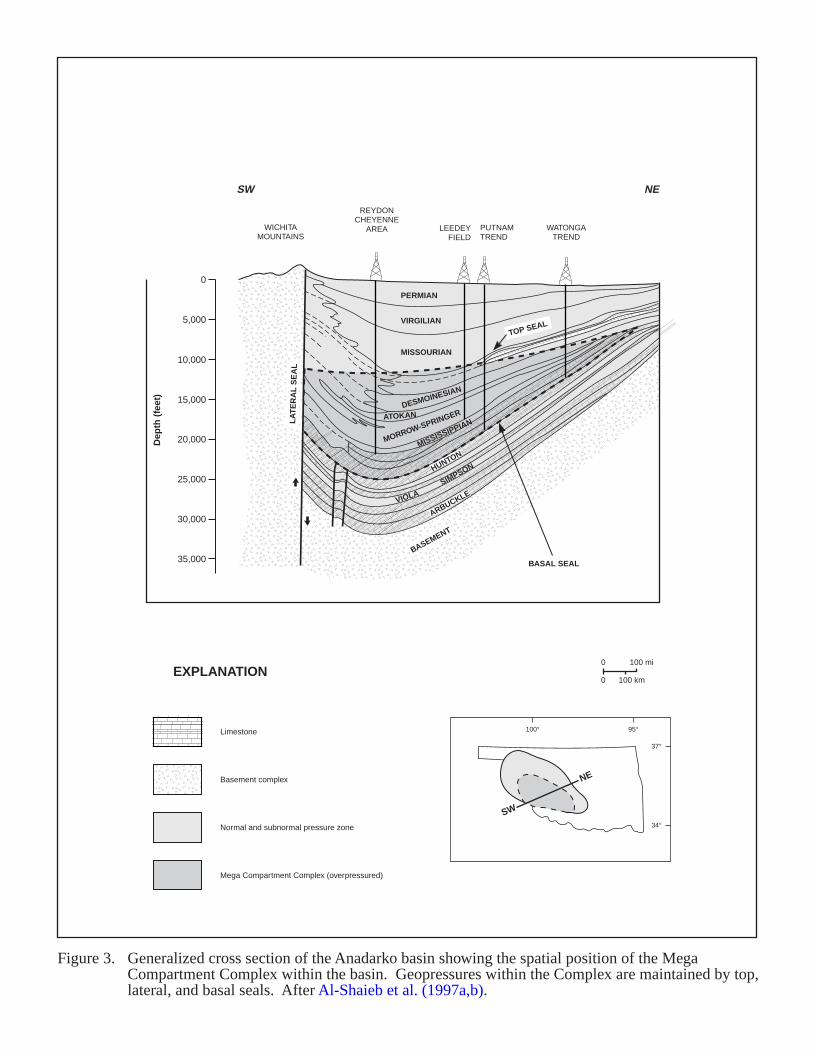
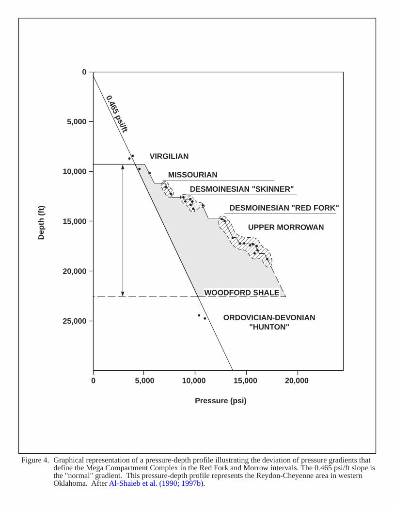
Strong evidence for a basin-centered gas accumulation is present in the form of thermally mature source rocks,widespread production and shows of gas, and overpressuring (Figure 3) that cuts across stratigraphic boundaries. Highpressure gradients occur within the Red Fork and Morrow Sandstones. The Woodford shale forms the base of thepressure cell (Figure 4); the top of the cell climbs stratigraphically into the basin (Al-Shaieb et al. (1990) termedthis regional overpressured cell a “Megacompartment Complex” or MCC). Vitrinite reflectance values for theWoodford follow this same general trend. The Pennsylvanian Atokan source rocks may exhibit these samematuration trends.
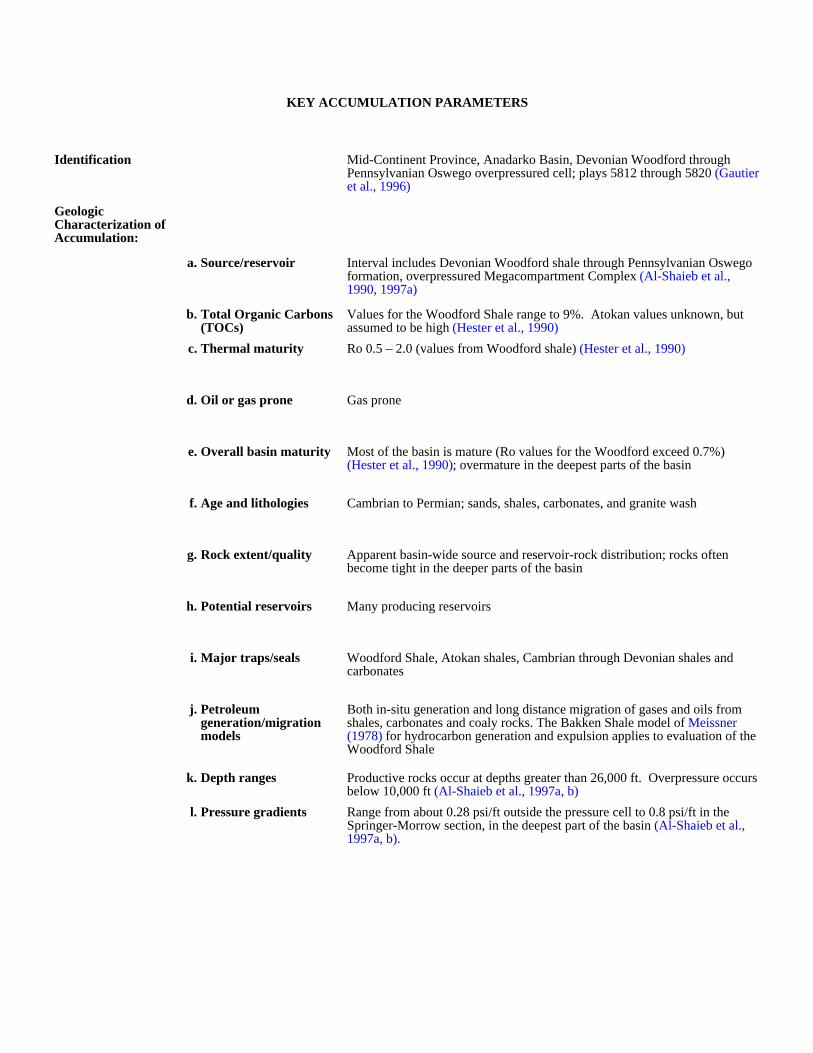
KEY ACCUMULATION PARAMETERS
Identification Mid-Continent Province, Anadarko Basin, Devonian Woodford through Pennsylvanian Oswego overpressured cell; plays 5812 through 5820 (Gautier et al., 1996)
Geologic Characterization of Accumulation:
a. Source/reservoir Interval includes Devonian Woodford shale through Pennsylvanian Oswego formation, overpressured Megacompartment Complex (Al-Shaieb et al., 1990, 1997a)
b. Total Organic Carbons (TOCs)
Values for the Woodford Shale range to 9%. Atokan values unknown, but assumed to be high (Hester et al., 1990)
c. Thermal maturity Ro 0.5 – 2.0 (values from Woodford shale) (Hester et al., 1990)
d. Oil or gas prone Gas prone
e. Overall basin maturity Most of the basin is mature (Ro values for the Woodford exceed 0.7%) (Hester et al., 1990); overmature in the deepest parts of the basin
f. Age and lithologies Cambrian to Permian; sands, shales, carbonates, and granite wash
g. Rock extent/quality Apparent basin-wide source and reservoir-rock distribution; rocks often become tight in the deeper parts of the basin
h. Potential reservoirs Many producing reservoirs
i. Major traps/seals Woodford Shale, Atokan shales, Cambrian through Devonian shales and carbonates
j. Petroleum generation/migration models
Both in-situ generation and long distance migration of gases and oils from shales, carbonates and coaly rocks. The Bakken Shale model of Meissner (1978) for hydrocarbon generation and expulsion applies to evaluation of the Woodford Shale
k. Depth ranges Productive rocks occur at depths greater than 26,000 ft. Overpressure occurs below 10,000 ft (Al-Shaieb et al., 1997a, b)
l. Pressure gradients Range from about 0.28 psi/ft outside the pressure cell to 0.8 psi/ft in the Springer-Morrow section, in the deepest part of the basin (Al-Shaieb et al., 1997a, b).

Production and Drilling Characteristics:
a. Important fields/reservoirs
Many fields produce from Cambrian through Permian rocks: Washita Creek field in Hemphill County, Texas, at the west end of the basin (from the Cambro-Ordovician at a depth of 24,450 ft; single well reserves as high as
24 BCFG); Knox field near the southeastern flank of the basin (from Bromide (Simpson) production at 15,310 ft depth; single well reserves as high as 6.2 BCFG) (Al-Shaieb et al., 1997b); Berlin field in Beckham
County, Oklahoma (from the Pennsylvanian Atokan formation; estimated ultimate recovery of 362 BCFG at 15,000 ft depth (Lyday, 1990))
b. Cumulative production
Economic Characteristics:
a. Inert gas content Gases are generally high in Btu content and low in total inert gases
b. Recovery Recoveries vary depending on permeability, porosity and depth
c. Pipeline infrastructure Very good
d. Exploration maturity relative to other basins
e. Sediment consolidation Most rocks are well indurated
f. Porosity/completion problems
Shales, tightly cemented sands and other tight (low permeability rocks) have the potential to produce where naturally fractured (many deep Anadarko Basin fields have permeabilities of less than 0.1 md). Water sensitive clays also cause problems.
g. Permeability Ranges from less than 0.08 up to 6,000 md.
h. Porosity Highly variable.
Oklahoma
Texas
NORTHERN OKLAHOMAPLATFORM
CENTRAL OKLAHOMA
PLATFORM
OZARK
UPLIFT
AMARILLO
UPLIFT
ANADARKO BASIN
HUNTON-PAULS VALLEY
UPLIFTWICHITA-CRINER
UPLIFT ARBUCKLEUPLIFT
ARDMOREBASIN
MARIETTA BASIN
MUENSTER-WAURIKA ARCH
OUACHITA SYSTEM
RED RIVER UPLIFT
ARKOMA BASIN
100 mi0
0 100 km
Figure 1. Tectonic map showing location of the Anadarko basin and the major structural features of Oklahoma. After Arbenz (1956), Al-Shaieband Shelton (1977), and Al-Shaieb et al. (1997a,b).
BeckhamCounty
HemphillCounty
100° 96°
37°
36°
35°
34°
98°
PENNSYLVANIAN
PERMIAN
MISSISSIPPIAN
SILURO-DEVONIAN
ORDOVICIAN
CAMBRIAN
BROWN DOLOMITE
HEEBNER
TONKAWA
MEDRANO
MARCHAND
OSWEGORED FORK
ATOKA
MORROW
CHERT-
CONGLOMERATE
WEDGE
SPRINGER
CHESTER
MERAMEC
OSAGE
WOODFORD
HUNTON
SYLVAN
VIOLA
SIMPSON
ARBUCKLE
REAGAN
BASEMENT
AR
KO
SIC
WE
DG
E
ME
GA
CO
MPA
RT
ME
NT
CO
MP
LE
XL
OC
AL
IZE
DO
VE
RP
RE
SS
UR
ED
CO
MPA
RT
ME
NT
S
Dolomite
Limestone
Chert & conglomerate
Shale
Sandstone
Basement complex
Tuff breccia
Figure 2. Generalized stratigraphic column of the Anadarko basin showing the intervals contained withinthe Mega Compartment Complex and the stratigraphic position of two localized overpressured compartments outside the Mega Compartment Complex. After Evans (1979) and Al-Shaieb et al.(1997a).
EXPLANATION
20,000
15,000
10,000
5,000
0
25,000
30,000
35,000
Dep
th (
feet
)
PERMIAN
VIRGILIAN
ATOKAN
HUNTON
SIMPSON
ARBUCKLE
BASEMENT
VIOLA
MISSOURIAN
MISSISSIPPIAN
MORROW-SPRINGERDESMOINESIAN
LA
TE
RA
L S
EA
L
TOP SEAL
BASAL SEAL
100 mi0
0 100 km
SW
NE
Figure 3. Generalized cross section of the Anadarko basin showing the spatial position of the Mega Compartment Complex within the basin. Geopressures within the Complex are maintained by top,lateral, and basal seals. After Al-Shaieb et al. (1997a,b).
SW NE
Basement complex
Limestone
Normal and subnormal pressure zone
Mega Compartment Complex (overpressured)
EXPLANATION
100° 95°
37°
34°
LEEDEYFIELD
REYDONCHEYENNE
AREAWICHITAMOUNTAINS
PUTNAMTREND
WATONGATREND
0
5,000
10,000
15,000
20,000
25,000
0 5,000 10,000
Pressure (psi)
Dep
th (
ft)
15,000 20,000
Figure 4. Graphical representation of a pressure-depth profile illustrating the deviation of pressure gradients thatdefine the Mega Compartment Complex in the Red Fork and Morrow intervals. The 0.465 psi/ft slope isthe "normal" gradient. This pressure-depth profile represents the Reydon-Cheyenne area in western Oklahoma. After Al-Shaieb et al. (1990; 1997b).
ORDOVICIAN-DEVONIAN"HUNTON"
UPPER MORROWAN
DESMOINESIAN "RED FORK"
DESMOINESIAN "SKINNER"
MISSOURIAN
WOODFORD SHALE
VIRGILIAN
0.465 psi/ft
21
APPALACHIAN BASIN (CLINTON-MEDINA AND OLDER FORMATIONS)
GEOLOGIC SETTING
The Appalachian basin extends southwestward from the Adirondack Mountains in New York to central Alabama.Figure 5 includes the area’s location . Structural boundaries include the Cincinnati arch on the west (in western Ohioand Kentucky), and the Allegheny Front on the east (in West Virginia and Pennsylvania). The basin is about 900miles long and 300 miles wide and includes at least 100 million surface acres (Roth, 1964).
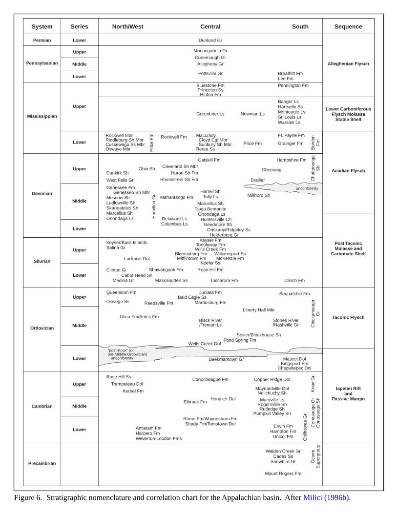
The Appalachian basin originated as a sedimentary trough on the Precambrian surface that was later covered byCambrian seas. Deposition of great masses of marine and continental sediments occurred throughout the PaleozoicEra. Carbonate and siliclastic tongues extended basinward from opposite margins synchronously in response to sealevel drops. The interplay of eustatic sea-level drop and local tectonic uplift resulted in stratigraphic sequencesbounded by widespread unconformities (Brett et al., 1990). Figure 6 shows correlation of the stratigraphy across thebasin. Three major orogenic events affected the basin: the Taconic Orogeny (Late Ordovician), the Acadian Orogeny(Late Devonian), and the Allegheny Orogeny (Late Permian).
The geotectonic history of the basin includes the following stages:
1) Precambrian: metamorphic and igneous rocks of the Grenville deformation form a basement under theAppalachian Foreland.
2) Early and Middle Cambrian: offset of the basement surface associated with the formation of the IapetusOcean during Late Precambrian and Early Cambrian (Schumaker, 1996).
3) Upper Cambrian-Middle Ordovician: relative crustal stability and the formation of a broad carbonate shelf.In the Middle Ordovician, a Foreland basin develops from compression of the passive, carbonate-dominatedcontinental margin during collision with an island arc system (Taconic Orogeny). Thick turbidite sequencesrecord the early phases of the orogeny.
4) Late Ordovician (Ashgillian): waning of the main Taconic pulse, and deposition of the Bald Eagle-Oswegosandstone wedge and the Juniata-Queenston red bed sequences.
5) Late Ordovician to Early Silurian: tectonic rejuvenation of the Taconic Front. In New York State, evidencefor a late Taconic pulse lies in the regionally extensive, low-angle unconformity at the Ordovician-Silurianboundary (Cherokee Unconformity).
6) Early Silurian (Cherokee Unconformity) and Late Silurian (Salinic Unconformity): eastward subsidence ofthe Appalachian Foreland Basin, which coincides with tectonic quiescence and thrust-load relaxation. Athick Early Silurian clastic wedge results from this subsidence. Westward migration in the foreland basinoccurred during the Middle Silurian, depositing finer-grained strata; increased tectonism and onset of theSalinic Disturbance may have caused this migration. A small-scale unconformity at the Siluro-Devonianboundary may represent the latest Silurian tectonic activity (Brett et al., 1990).
7) Devonian-Late Permian: The Acadian (Devonian) and Allegheny orogenies (Late Permian) correlate to thecollision of the North American plate with other continental plates, eventually creating Pangaea at the endof the Paleozoic (Schumaker, 1996). During the Allegheny (Appalachian) Orogeny, tremendous thrustpulses from the east and southeast intensely folded and faulted the rocks in the eastern area. The deformationbecomes gradually less intense westward. The Ridge and Valley province shows the greatest folding ofrocks. The Allegheny Orogeny primarily determined the present day geologic pattern dividing the area intotwo main parts–the Plateau province, and the Ridge and Valley province (Roth, 1964).
22
HYDROCARBON PRODUCTION
The Appalachian basin has the longest history of oil and gas production in the United States. Since Drake'sTitusville discovery well in 1859, oil and gas has been continuously produced in the basin. Although opportunitiesfor oil and gas still exist (Petzet, 1991), new field discoveries are rare, and the Appalachian basin has been considereda mature petroleum province as most of the significant plays have been already discovered and developed.
Conventional Plays: Production from Late Cambrian to Late Ordovician rocks is considered conventional:
(1) The Upper Ordovician Queenston Formation produces gas from sandstones and sandy facies trapped in low-amplitude anticlines and fractures.
(2) The Middle Ordovician Trenton play produces from fractured micrite in the transition zone between theTrenton limestone and the overlying Utica Shale (Ryder et al., 1995).
(3) The Middle Ordovician St. Peter sandstone produces from structural traps.
(4) The Late Cambrian-Late Ordovician Knox Dolomite produces from structural and stratigraphic traps.
(5) The Cambrian pre-Knox Group (Conasauga Fm., Rome Fm., and Mt. Simon Sandstone) is extensive andunderlies the productive "Clinton"/Medina play area. This play has had limited production and may stillhave potential for future gas production, including basin-centered gas. The section has been sparsely drilled,and thick untested intervals remain in parts of the Rome trough and other areas. Production from pre-Knoxrocks has been limited to scattered wells in Kentucky, West Virginia, and Ontario, Canada. The areaunderlying the Clinton/Medina gas play is considered a low-risk area and has estimated recoverable gasresources of 460 BCF (Harris and Baranoski, 1996).
Unconventional Plays: The oldest producing gas plays in the basin are Upper Devonian black shales andsandstones. These plays include conventional to unconventional continuous-type accumulations. Milici (1996a,1996b) noted the black shales serve both as source rocks and as reservoirs for gas. Production to date has yieldedabout 3.0 TCF, and estimates for recoverable reserves reach about 20 TCF (Charpentier et al., 1993).
Basin-centered gas plays: The Lower Silurian "Clinton" sands/Medina Group sandstones gas play is underdevelopment in New York, Pennsylvania and Ohio (Figure 5). Development of this basin-centered gas play hasexpanded since the early 1970s. Ryder (1996) estimated the Appalachian basin to have about 61 trillion (TCF)recoverable gas within Paleozoic sandstones and shales. An estimated 30 TCF may reside in basin-centered gasaccumulations in the Lower Silurian "Clinton"/Medina sandstones. Cumulative gas production per well is relativelylow. This play appears attractive for four reasons: the overall success rate approaches 90%; the drilling anddevelopment costs remain low; there is low water production (and hence, low disposal costs); and the proximity topopulation centers provides a market for the gas. To maximize gas recovery, operators drill closely spaced (40 acre)wells and horizontal/directional wells. Hydraulic fracturing techniques improved production success from lowpermeability sandstone reservoirs.
Ryder (1996) defined four continuous-type gas plays (6728-6731) in the "Clinton”/Medina sandstones interval,flanked by two conventional plays that also have potential for continuous-type gas (6732, Clinton-Medina SandstoneOil/Gas; and 6727, Tuscarora Sandstone Gas). Figure 5 shows locations of basin-centered gas accumulations. Play6728 (Clinton/Medina Gas High Potential) has the best production potential and covers 16,901 square miles. Sourcerocks for these plays include Middle to Upper Devonian black shales, and Middle Ordovician Utica and Antes Shales.
23
The depositional sequence of the "Clinton"/Medina sandstones include the basal Whirlpool Sandstone andMedina Group, which unconformably overlie the Upper Ordovician Queenston Shale. These units representtransgressive shoreface deposits with a lowermost braided fluvial component. The lower part of the "Clinton" sandsare shoreface deposits. These sandstones constitute parts of progradational parasequences that successively overlapone another toward the northwest, pinch out seaward into the offshore marine Cabot Head Shale, and then appear todownlap across the underlying transgressive systems. Ryder et al. (1996) interprets the named sandstones in theCabot Head Shale to be part of a progradational stacked-parasequence. Limestones within the Cabot Head appear tobe offshore carbonates separated by inner shelf mudrocks (Keighin, 1998). These limestones are regionally extensive,but do have pinchouts and thickness changes in the intervening shale beds (Ryder et al., 1996).
EVIDENCE FOR BASIN-CENTERED GAS
While productive Cambrian and Ordovician reservoirs apparently are conventional gas plays, and Devonianshales and sandstones harbor conventional to unconventional continuous-type accumulations, a basin-centeredhydrocarbon accumulation may exist in the "Clinton"/Medina sandstones, especially in play 6728 (Clinton/MedinaGas High Potential) (Ryder et al., 1996; Ryder, 1996, 1998; Wandrey et al., 1997):
(1) Regionally extensive sandstones with a thick zone of gas saturation reside in the thicker, more deeply buriedpart of this foreland basin. Sandstone thickness ranges from 120 to 210 ft, and average net thickness is 25ft; sandstone-to-shale ratios range from 0.6 to 1.0.
(2) Gas fields are coalesced, and a high percentage of wells have production or gas shows.
(3) Reservoirs have low porosity and permeability; porosity ranges from 3 to 11% (averaging 5%).Permeability ranges from 0.2 to 0.6 mD (generally averaging less than 0.01 mD).
(4) Formation pressures are abnormally low with a gradient ranging from 0.25 to 0.35 psi/ft. In the TuscaroraSandstone Gas (play 6727), there is evidence for overpressuring with a gradient ranging between 0.50-0.60psi/ft.
(5) Structural traps are few.
(6) A gas-water contact is absent.
(7) Sandstones with higher water saturations are updip of the gas accumulation.
(8) Water yields are low; reservoir water saturation is less than 9 to 13 BW/MMCFG.
(9) Reservoir temperatures are high–at least 125° F (52° C).
KEY ACCUMULATION PARAMETERS
Identification Eastern U.S. Appalachian basin. Play: Paleozoic Era - Late Cambrian and Ordovician sandstones and shales; Lower Silurian "Clinton" and Medina Group sandstones, and the equivalent Tuscarora Sandstone
Geologic Characterization of Accumulation:
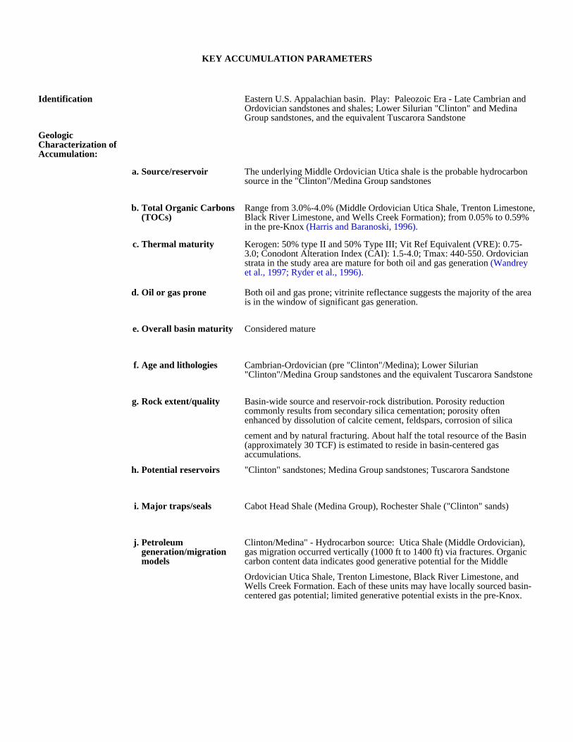
a. Source/reservoir The underlying Middle Ordovician Utica shale is the probable hydrocarbon source in the "Clinton"/Medina Group sandstones
b. Total Organic Carbons (TOCs)
Range from 3.0%-4.0% (Middle Ordovician Utica Shale, Trenton Limestone, Black River Limestone, and Wells Creek Formation); from 0.05% to 0.59% in the pre-Knox (Harris and Baranoski, 1996).
c. Thermal maturity Kerogen: 50% type II and 50% Type III; Vit Ref Equivalent (VRE): 0.75-3.0; Conodont Alteration Index (CAI): 1.5-4.0; Tmax: 440-550. Ordovician strata in the study area are mature for both oil and gas generation (Wandrey et al., 1997; Ryder et al., 1996).
d. Oil or gas prone Both oil and gas prone; vitrinite reflectance suggests the majority of the area is in the window of significant gas generation.
e. Overall basin maturity Considered mature
f. Age and lithologies Cambrian-Ordovician (pre "Clinton"/Medina); Lower Silurian "Clinton"/Medina Group sandstones and the equivalent Tuscarora Sandstone
g. Rock extent/quality Basin-wide source and reservoir-rock distribution. Porosity reduction commonly results from secondary silica cementation; porosity often enhanced by dissolution of calcite cement, feldspars, corrosion of silica
cement and by natural fracturing. About half the total resource of the Basin (approximately 30 TCF) is estimated to reside in basin-centered gas accumulations.
h. Potential reservoirs "Clinton" sandstones; Medina Group sandstones; Tuscarora Sandstone
i. Major traps/seals Cabot Head Shale (Medina Group), Rochester Shale ("Clinton" sands)
j. Petroleum generation/migration models
Clinton/Medina" - Hydrocarbon source: Utica Shale (Middle Ordovician), gas migration occurred vertically (1000 ft to 1400 ft) via fractures. Organic carbon content data indicates good generative potential for the Middle
Ordovician Utica Shale, Trenton Limestone, Black River Limestone, and Wells Creek Formation. Each of these units may have locally sourced basin-centered gas potential; limited generative potential exists in the pre-Knox.
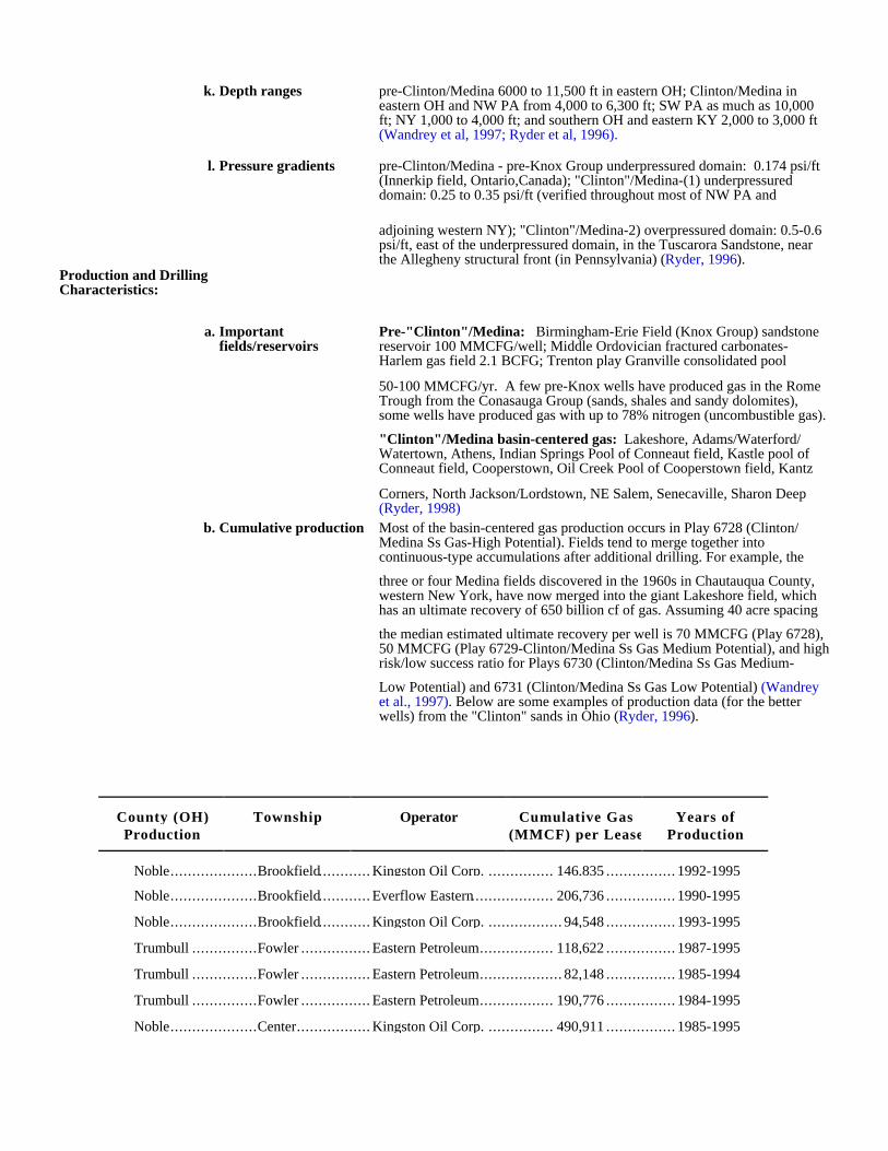
k. Depth ranges pre-Clinton/Medina 6000 to 11,500 ft in eastern OH; Clinton/Medina in eastern OH and NW PA from 4,000 to 6,300 ft; SW PA as much as 10,000 ft; NY 1,000 to 4,000 ft; and southern OH and eastern KY 2,000 to 3,000 ft (Wandrey et al, 1997; Ryder et al, 1996).
l. Pressure gradients pre-Clinton/Medina - pre-Knox Group underpressured domain: 0.174 psi/ft (Innerkip field, Ontario,Canada); "Clinton"/Medina-(1) underpressured domain: 0.25 to 0.35 psi/ft (verified throughout most of NW PA and
adjoining western NY); "Clinton"/Medina-2) overpressured domain: 0.5-0.6 psi/ft, east of the underpressured domain, in the Tuscarora Sandstone, near the Allegheny structural front (in Pennsylvania) (Ryder, 1996).
Production and Drilling Characteristics:
a. Important fields/reservoirs
Pre-"Clinton"/Medina: Birmingham-Erie Field (Knox Group) sandstone reservoir 100 MMCFG/well; Middle Ordovician fractured carbonates-Harlem gas field 2.1 BCFG; Trenton play Granville consolidated pool
50-100 MMCFG/yr. A few pre-Knox wells have produced gas in the Rome Trough from the Conasauga Group (sands, shales and sandy dolomites), some wells have produced gas with up to 78% nitrogen (uncombustible gas).
"Clinton"/Medina basin-centered gas: Lakeshore, Adams/Waterford/ Watertown, Athens, Indian Springs Pool of Conneaut field, Kastle pool of Conneaut field, Cooperstown, Oil Creek Pool of Cooperstown field, Kantz
Corners, North Jackson/Lordstown, NE Salem, Senecaville, Sharon Deep (Ryder, 1998)
b. Cumulative production Most of the basin-centered gas production occurs in Play 6728 (Clinton/ Medina Ss Gas-High Potential). Fields tend to merge together into continuous-type accumulations after additional drilling. For example, the
three or four Medina fields discovered in the 1960s in Chautauqua County, western New York, have now merged into the giant Lakeshore field, which has an ultimate recovery of 650 billion cf of gas. Assuming 40 acre spacing
the median estimated ultimate recovery per well is 70 MMCFG (Play 6728), 50 MMCFG (Play 6729-Clinton/Medina Ss Gas Medium Potential), and high risk/low success ratio for Plays 6730 (Clinton/Medina Ss Gas Medium-
Low Potential) and 6731 (Clinton/Medina Ss Gas Low Potential) (Wandrey et al., 1997). Below are some examples of production data (for the better wells) from the "Clinton" sands in Ohio (Ryder, 1996).
County (OH)Production
Township Operator Cumulative Gas(MMCF) per Lease
Years ofProduction
Noble....................Brookfield............ Kingston Oil Corp. ............... 146,835 ................ 1992-1995
Noble....................Brookfield............ Everflow Eastern................... 206,736 ................ 1990-1995
Noble....................Brookfield............ Kingston Oil Corp. ................. 94,548 ................ 1993-1995
Trumbull ...............Fowler ................ Eastern Petroleum................. 118,622 ................ 1987-1995
Trumbull ...............Fowler ................ Eastern Petroleum................... 82,148 ................ 1985-1994
Trumbull ...............Fowler ................ Eastern Petroleum................. 190,776 ................ 1984-1995
Noble....................Center................. Kingston Oil Corp. ............... 490,911 ................ 1985-1995
Economic Characteristics:
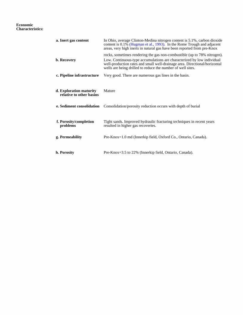
a. Inert gas content In Ohio, average Clinton-Medina nitrogen content is 5.1%, carbon dioxide content is 0.1% (Hugman et al., 1993). In the Rome Trough and adjacent areas, very high inerts in natural gas have been reported from pre-Knox
rocks, sometimes rendering the gas non-combustible (up to 78% nitrogen).b. Recovery Low. Continuous-type accumulations are characterized by low individual
well-production rates and small well-drainage area. Directional/horizontal wells are being drilled to reduce the number of well sites.
c. Pipeline infrastructure Very good. There are numerous gas lines in the basin.
d. Exploration maturity relative to other basins
Mature
e. Sediment consolidation Consolidation/porosity reduction occurs with depth of burial
f. Porosity/completion problems
Tight sands. Improved hydraulic fracturing techniques in recent years resulted in higher gas recoveries.
g. Permeability Pre-Knox=1.0 md (Innerkip field, Oxford Co., Ontario, Canada).
h. Porosity Pre-Knox=3.5 to 22% (Innerkip field, Ontario, Canada).

Kentucky
Ohio
West Virginia
Pennsylvania
New York
Ontario
Lake Erie
Lake Ontario
Allegh
eny
Fr
ont
Cin
cinn
ati
Arc
hR
ome
Trough
1
2
3 45
87
6
109
12
14
13
15
11
123
456789
101112131415
InnerkipLakeshoreIndian Springs pool of Conneaut fieldKastle pool of Conneaut fieldAthensKantz CornersCooperstownOil Cr pool of Cooperstown fieldNorth Jackson/LordstownSharon DeepBirmingham-ErieNortheast SalemSenecavilleAdams/Waterford/WatertownGranville Consolidated pool of Trenton Play
Fields
0 50 mi
N
Sandstone reservoir for gas
Sandstone reservoir for oil
Oil and gas field
Basin-centered gas accumulation
Approximate updip limit of basin- centered gas accumulation
Approximate updip limit of Tuscarora Sandstone
Well location with show of gas or oil
Figure 5. Map showing regional hydrocarbon accumulation in Lower Silurian sandstone reservoirs of the Appalachianbasin. Oil and gas shows seen in wells are from pre-Knox units. After Harris and Baranoski (1996), and Ryder (1998).
System
Permian Lower Dunkard Gr
Alleghenian Flysch
Acadian Flysch
Taconic Flysch
Iapetan Riftand
Passive Margin
Lower CarboniferousFlysch Molasse
Stable Shelf
Post TaconicMolasse and
Carbonate Shelf
Monongahela Gr
Conemaugh GrAllegheny Gr
Pottsville Gr Breathitt FmLee Fm
Pennington Fm
Bangor LsHartselle SsMonteagle LsSt. Louis LsWarsaw Ls
Ft. Payne Fm
Hampshire Fm
Chemung
Brallier
Grainger Fm
Newman Ls
Price Fm
Ohio ShDunkirk Sh
Lockport Dol
Cabot Head Sh
Queenston Fm
Oswego Ss
Rose Hill Ss
Trempeleau Dol
Kerbel Fm
Clinton Gr
Medina Gr
Keyser/Bass IslandsSalina Gr
West Falls Gr
Genessee Fm
Moscow ShLudlowville ShSkaneateles ShMarcellus ShOnondaga Ls
Genesseo Sh Mbr
Pric
e F
mH
amilt
on G
r
Rockwell Fm
Greenbrier Ls
Keyser FmTonoloway FmWills Creek Fm
Bloomsburg Fm Williamsport SsMifflintown Fm McKenzie Fm
Keefer Ss
Rose Hill Fm
Wells Creek Dol
Beekmantown Gr
Juniata FmBald Eagle Ss
Martinsburg Fm
Tuscarora Fm Clinch Fm
Sequatchie Fm
Erwin FmHampton Fm
Unicoi Fm
Walden Creek GrCades Ss
Snowbird Gr
Mount Rogers Fm
Copper Ridge Dol
Maynardville DolNolichuchy Sh
Conocheague Fm
Rome Fm/Waynesboro FmShady Fm/Tomstown Dol
Honaker DolElbrook Fm
Mascot DolKingsport Fm
Chepultepec Dol
Catskill Fm Cleveland Sh Mbr
Huron Sh FmRhinestreet Sh Fm
Harrell ShTully Ls
Black River/Trenton Ls
Mahantango Fm
Delaware LsColumbus Ls
Bluestone FmPrinceton SsHinton Fm
Maccrady Cloyd Cgl Mbr Sunbury Sh MbrBerea Ss
Rockwell MbrRiddleburg Sh MbrCussewago Ss MbrOswayo Mbr
Upper
Upper
Upper
Middle
Middle
Upper
Upper
Middle
Lower
Lower
Lower
Lower
Lower
Middle
Upper
Lower
Pennsylvanian
Mississippian
Devonian
Silurian
Ordovician
Cambrian
Precambrian
SequenceSeries North/West Central South
Bor
den
Fm
Cha
ttano
oga
Sh
Chi
ckam
auga
Gr
Kno
x G
rC
onas
auga
Gr
Con
asau
ga S
hO
coee
Sup
ergr
oup
Chi
lhow
ee G
r
Millboro Sh
Reedsville Fm
Utica Fm/Antes Fm
Liberty Hall Mbr
Stones River/Nashville Gr
Sevier/Blockhouse ShPond Spring Fm
Marcellus ShTioga Bentonite Onondaga Ls
Huntersville Ch Needmore Sh
Oriskany/Ridgeley Ss Helderberg Gr
Shawangunk Fm
Antietam FmHarpers FmWeverton-Loudon Fms
Massanutten Ss
Maryville LsRogersville ShRutledge Sh
Pumpkin Valley Sh
unconformity
"post-Knox" (or pre-Middle Ordovician) unconformity
Figure 6. Stratigraphic nomenclature and correlation chart for the Appalachian basin. After Milici (1996b).
29
ARKOMA BASIN
GEOLOGIC SETTING
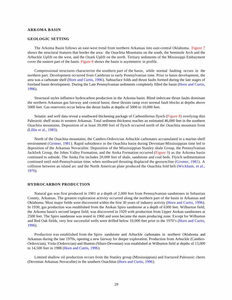
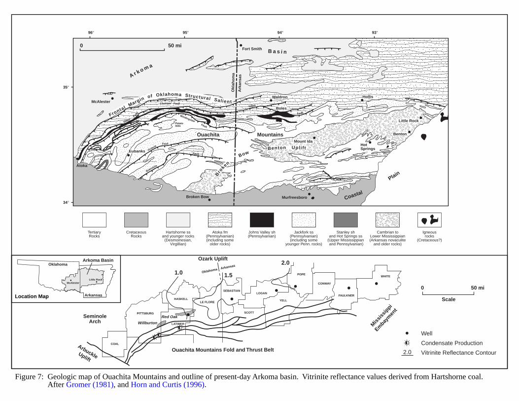
The Arkoma Basin follows an east-west trend from northern Arkansas into east-central Oklahoma. Figure 7shows the structural features that border the area: the Ouachita Mountains on the south, the Seminole Arch and theArbuckle Uplift on the west, and the Ozark Uplift on the north. Tertiary sediments of the Mississippi Embaymentcover the eastern part of the basin. Figure 8 shows the basin is asymmetric in profile.
Compressional structures characterize the southern part of the basin, while normal faulting occurs in thenorthern part. Development occurred from Cambrian to early Pennsylvanian time. Prior to basin development, thearea was a carbonate shelf (Horn and Curtis, 1996). Subsurface folds and thrust faults formed during the late stages offoreland basin development. During the Late Pennsylvanian sediments completely filled the basin (Horn and Curtis,1996).
Structural styles influence hydrocarbon production in the Arkoma basin. Blind imbricate thrust faults dominatethe northern Arkansas gas fairway and central basin; these thrusts ramp over normal fault blocks at depths above5000 feet. Gas reservoirs occur below the thrust faults at depths of 5000 to 10,000 feet.
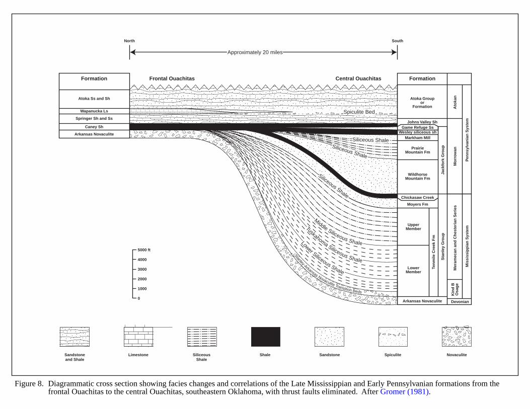
Seismic and well data reveal a southward thickening package of Carboniferous flysch (Figure 8) overlying thinPaleozoic shelf strata in western Arkansas. Total sediment thickness reaches an estimated 46,000 feet in the southernOuachita mountains. Deposition of at least 39,000 feet of flysch occurred north of the Ouachita mountain front(Lillie et al., 1983).
North of the Ouachita mountains, the Cambro-Ordovician Arbuckle carbonates accumulated in a marine-shelfenvironment (Gromer, 1981). Rapid subsidence in the Ouachita basin during Devonian-Mississippian time led todeposition of the Arkansas Novaculite. Deposition of the Mississippian Stanley shale Group, the PennsylvanianJackfork Group, the Johns Valley Formation, and the Atoka Formation occurred (Figure 9) as the Arkoma basincontinued to subside. The Atoka Fm includes 20,000 feet of shale, sandstone and coal beds. Flysch sedimentationcontinued until mid-Pennsylvanian time, when northward thrusting displaced the geosyncline (Gromer, 1981). Acollision between an island arc and the North American plate produced the Ouachita fold belt (Wickham, et al.,1976).
HYDROCARBON PRODUCTION
Natural gas was first produced in 1901 at a depth of 2,000 feet from Pennsylvanian sandstones in SebastianCounty, Arkansas. The greatest exploration activity occurred along the northern part of the basin in Arkansas andOklahoma. Most major fields were discovered within the first 30 years of industry activity (Horn and Curtis, 1996).In 1930, gas production was established from the Atokan Spiro sandstone at a depth of 6300 feet. Wilburton field,the Arkoma basin's second largest field, was discovered in 1929 with production from Upper Atokan sandstones at2500 feet. The Spiro sandstone was tested in 1960 and soon became the main producing zone. Except for Wilburtonand Red Oak fields, very few successful wells were drilled below 10,000 feet prior to the 1970’s (Horn and Curtis,1996).
Production was established from the Spiro sandstone and Arbuckle carbonates in northern Oklahoma andArkansas during the late 1970s, opening a new fairway for deeper exploration. Production from Arbuckle (Cambro-Ordovician), Viola (Ordovician) and Hunton (Siluro-Devonian) was established at Wilburton field at depths of 13,000to 14,500 feet in 1988 (Horn and Curtis, 1996).
Limited shallow oil production occurs from the Stanley group (Mississippian) and fractured Paleozoic cherts(Devonian Arkansas Novaculite) in the southern Ouachitas (Horn and Curtis, 1996).
30
EVIDENCE FOR BASIN-CENTERED GAS
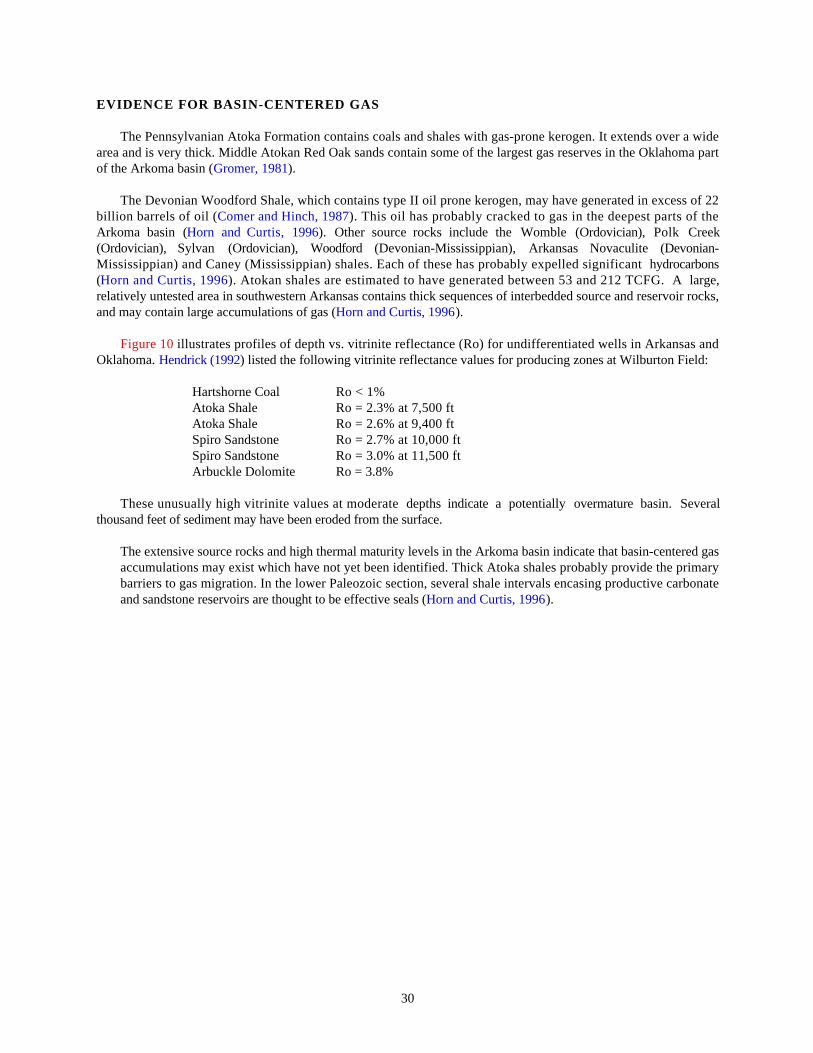
The Pennsylvanian Atoka Formation contains coals and shales with gas-prone kerogen. It extends over a widearea and is very thick. Middle Atokan Red Oak sands contain some of the largest gas reserves in the Oklahoma partof the Arkoma basin (Gromer, 1981).
The Devonian Woodford Shale, which contains type II oil prone kerogen, may have generated in excess of 22billion barrels of oil (Comer and Hinch, 1987). This oil has probably cracked to gas in the deepest parts of theArkoma basin (Horn and Curtis, 1996). Other source rocks include the Womble (Ordovician), Polk Creek(Ordovician), Sylvan (Ordovician), Woodford (Devonian-Mississippian), Arkansas Novaculite (Devonian-Mississippian) and Caney (Mississippian) shales. Each of these has probably expelled significant hydrocarbons(Horn and Curtis, 1996). Atokan shales are estimated to have generated between 53 and 212 TCFG. A large,relatively untested area in southwestern Arkansas contains thick sequences of interbedded source and reservoir rocks,and may contain large accumulations of gas (Horn and Curtis, 1996).
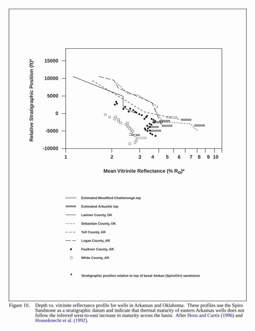
Figure 10 illustrates profiles of depth vs. vitrinite reflectance (Ro) for undifferentiated wells in Arkansas andOklahoma. Hendrick (1992) listed the following vitrinite reflectance values for producing zones at Wilburton Field:
Hartshorne Coal Ro < 1%Atoka Shale Ro = 2.3% at 7,500 ftAtoka Shale Ro = 2.6% at 9,400 ftSpiro Sandstone Ro = 2.7% at 10,000 ftSpiro Sandstone Ro = 3.0% at 11,500 ftArbuckle Dolomite Ro = 3.8%
These unusually high vitrinite values at moderate depths indicate a potentially overmature basin. Severalthousand feet of sediment may have been eroded from the surface.
The extensive source rocks and high thermal maturity levels in the Arkoma basin indicate that basin-centered gasaccumulations may exist which have not yet been identified. Thick Atoka shales probably provide the primarybarriers to gas migration. In the lower Paleozoic section, several shale intervals encasing productive carbonateand sandstone reservoirs are thought to be effective seals (Horn and Curtis, 1996).
KEY ACCUMULATION PARAMETERS
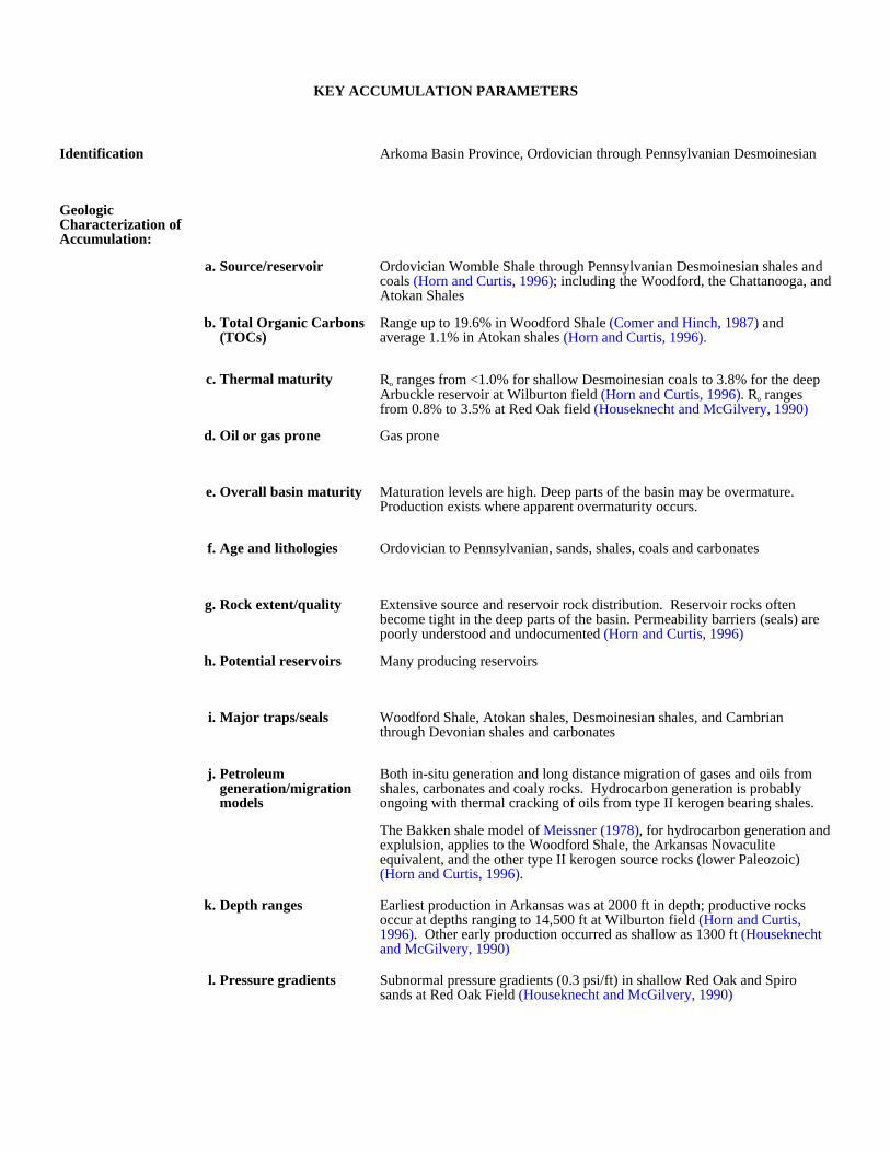
Identification Arkoma Basin Province, Ordovician through Pennsylvanian Desmoinesian
Geologic Characterization of Accumulation:
a. Source/reservoir Ordovician Womble Shale through Pennsylvanian Desmoinesian shales and coals (Horn and Curtis, 1996); including the Woodford, the Chattanooga, and Atokan Shales
b. Total Organic Carbons (TOCs)
Range up to 19.6% in Woodford Shale (Comer and Hinch, 1987) and average 1.1% in Atokan shales (Horn and Curtis, 1996).
c. Thermal maturity Ro ranges from <1.0% for shallow Desmoinesian coals to 3.8% for the deep Arbuckle reservoir at Wilburton field (Horn and Curtis, 1996). Ro ranges from 0.8% to 3.5% at Red Oak field (Houseknecht and McGilvery, 1990)
d. Oil or gas prone Gas prone
e. Overall basin maturity Maturation levels are high. Deep parts of the basin may be overmature. Production exists where apparent overmaturity occurs.
f. Age and lithologies Ordovician to Pennsylvanian, sands, shales, coals and carbonates
g. Rock extent/quality Extensive source and reservoir rock distribution. Reservoir rocks often become tight in the deep parts of the basin. Permeability barriers (seals) are poorly understood and undocumented (Horn and Curtis, 1996)
h. Potential reservoirs Many producing reservoirs
i. Major traps/seals Woodford Shale, Atokan shales, Desmoinesian shales, and Cambrian through Devonian shales and carbonates
j. Petroleum generation/migration models
Both in-situ generation and long distance migration of gases and oils from shales, carbonates and coaly rocks. Hydrocarbon generation is probably ongoing with thermal cracking of oils from type II kerogen bearing shales.
The Bakken shale model of Meissner (1978), for hydrocarbon generation and explulsion, applies to the Woodford Shale, the Arkansas Novaculite equivalent, and the other type II kerogen source rocks (lower Paleozoic) (Horn and Curtis, 1996).
k. Depth ranges Earliest production in Arkansas was at 2000 ft in depth; productive rocks occur at depths ranging to 14,500 ft at Wilburton field (Horn and Curtis, 1996). Other early production occurred as shallow as 1300 ft (Houseknecht and McGilvery, 1990)
l. Pressure gradients Subnormal pressure gradients (0.3 psi/ft) in shallow Red Oak and Spiro sands at Red Oak Field (Houseknecht and McGilvery, 1990)

Production and Drilling Characteristics:
a. Important fields/reservoirs
Red Oak Field produces from Pennyslvanian sandstones at depths ranging from 1400 ft to 13,000 ft; Wilburton Field produces from Cambro-Ordovician Arbuckle at depths from 13,000 to 14,500 ft.
b. Cumulative production Red Oak Field has produced 55 Bcfg from the Hartshorne, 700 Bcfg from the Red Oak, and 200 Bcfg from the Spiro sandstones as of 1987.
Economic Characteristics:
a. Inert gas content Gases have high btu content and low total inert gas content
b. Recovery Recoveries depend upon permeability, porosity and depth
c. Pipeline infrastructure Very good
d. Exploration maturity relative to other basins
Mature
e. Sediment consolidation Most rocks are well indurated
f. Porosity/completion problems
Shales, tightly cemented sands and other tight (low permeability) rocks have potential to produce where they are naturally fractured (many deep Arkoma Basin fields have permeabilities of less than 0.1 md). Water sensitive clays
also cause problems. Diagenetic permeability barriers are poorly understood.
g. Permeability 0.1-200 md
h. Porosity 5-23%
PotatoHills
Choctaw
Fault
Fault
Fault
ValleyFau
lt
Valley
Fault
Octavia
WindingstairFault
Boktufola
Bro
ken
Bow — Benton Uplif t
Frontal Marginof Oklahoma Structural Salien t
Ouachita Mountains
A r k o m a
B a s i n
Coastal
Plain
Fort Smith
McAlester
Atoka
Eubanks
Broken Bow Murfreesboro
Mount Ida
Waldron
Boles
Hollis
HotSprings
Benton
Little Rock
Okl
aho
ma
Ark
ansa
s
TertiaryRocks
CretaceousRocks
Hartshorne ssand younger rocks
(Desmoinesian,Virgillian)
Atoka fm(Pennsylvanian)(including some
older rocks)
Johns Valley sh(Pennsylvanian)
Stanley shand Hot Springs ss
(Upper Mississippian and Pennsylvanian)
Cambrian toLower Mississippian(Arkansas novaculite
and older rocks)
Igneousrocks
(Cretaceous?)
Jackfork ss(Pennsylvanian)(including some
younger Penn. rocks)
35°
96° 95° 94° 93°
34°
0 50 mi
Figure 7: Geologic map of Ouachita Mountains and outline of present-day Arkoma basin. Vitrinite reflectance values derived from Hartshorne coal. After Gromer (1981), and Horn and Curtis (1996).
Willburton
Red Oak
0 50 mi
Scale
SEBASTIAN
LE FLOREHASKELL
LATIMER
PITTSBURG
COAL
LOGAN
POPE
CONWAY
FAULKNER
WHITE
YELL
SCOTT
1.0 1.5
2.0
Vitrinite Reflectance Contour
Condensate Production
Well
2.0
Oklahoma Arkansas
Mis
siss
ippi
Embay
men
t
ArbuckleUplift
Ouachita Mountains Fold and Thrust Belt
SeminoleArch
Ozark Uplift
McAlesterLittle Rock
OklahomaArkoma Basin
ArkansasLocation Map
Formation Frontal Ouachitas
Approximately 20 miles
Central Ouachitas Formation
Atoka Ss and Sh Atoka Groupor
Formation
Johns Valley Sh
Spiculite Bed
Siliceous Shale
Siliceous Shale
Siliceous Shale
Arkansas Novaculite Devonian
Game Refuge SsWesley siliceous sh
Markham Mill
PrairieMountain Fm
WildhorseMountain Fm
Chickasaw Creek
Moyers Fm
UpperMember
Ten
mile
Cre
ek F
m
Sta
nle
y G
rou
p
Mer
amec
an a
nd
Ch
este
rian
Ser
ies
Mis
siss
ipp
ian
Sys
tem
Jack
fork
Gro
up
Mo
rro
wan
Ato
kan
Pen
nsy
lvan
ian
Sys
tem
Kin
d B
Osa
ge
LowerMember
Wapanucka Ls
Springer Sh and Ss
Caney Sh
Arkansas Novaculite
Middle Siliceous Shale
Tuskahoma Siliceous Shale
Lower Siliceous Shale
Stanley-Arkansas Novaculite Transition Beds
5000 ft
4000
3000
2000
1000
0
North South
Sandstoneand Shale
Limestone SiliceousShale
Shale Sandstone Spiculite Novaculite
Figure 8. Diagrammatic cross section showing facies changes and correlations of the Late Mississippian and Early Pennsylvanian formations from thefrontal Ouachitas to the central Ouachitas, southeastern Oklahoma, with thrust faults eliminated. After Gromer (1981).
Arkoma Foreland Basin Facies
OklahomaSystem
Pen
nsy
lvan
ian
Morrowan
Chesterian
Meramecian
Osagean
Kinder-hookian
Upperand
Middle
Lower
Niagaran
Alexandrian
Cha
mpl
aini
an
Cincinnatian
Canadian
Atokan
Cabaniss
Krebs Group
Salisaw FormationFrisco Formation
Welling FormationViola Springs Formation
BromideTulip Creek
MclishOil Creek
Joins
West Spring CreekKinblade
Cool CreekMcKenzie Hill
Butterfly Dolomite
Singal Mountain LimestoneRoyer Dolomite
Fort Sill Limestone
Honey Creek LimestoneReagen Sandstone
Henryhouse Formation
Chimneyhill SubgroupPetite Oolite
BoggySavannaMcAlester
Hartshorne Ss
BoggySavannaMcAlester
Hartshorne SsIIIII
<1.0 - 25
III
0.5 - 3.4
III0.5 - 3.4
Atoka FormationLynn Mountain Formation
Johns Valley Formation
Chicachoc Chert
Arkansas Novaculite
Missouri Mountain Shale
Blaylock Sandstone
Polk Creek Shale
Bigfork Chert
Womble Shale
Blakely Sandstone
Mazarn Shale
Crystal Mountain Sandstone
Collier Shale
Wapanucka LimestoneKesslerBloyd
BrentwoodHale
Pitkin LimestoneFayetteville Shale
Hindsville LimestoneMoorefield Formation
Game RefugeWesley
Markham MillPrairie Mountain
Wildhorse Mountain
Chickasaw Creek
MoyersTen Mile Creek
Boone Formation
Penters Chert
Fernvale LimestoneKimmswick Limestone, Plattin Limestone,
Joachim Dolomite
St. Peter Sandstone
SylvanCason Shale
Lafferty LimestoneSt. Clair Limestone
Brassfield Limestone
Tyner FormationJasper Limestone
King River Ss, Burgen Ss
Powell DolomiteCotter Dolomite
Jefferson City DolomiteRoubidoux Formation
Gasconade-Van Buren Formation
Eminence DolomitePolosi Dolomite
Derby-Doerun-Davis FormationBonneterre DolomiteLamontte Sandstone
Chattanooga Shale
Sylamore Sandstone
Dirty Creek, FanshaweDiamond, Red Oak
PanolaBrazil-Smallwood, Shay
Spiro
Goddard Shale
Caney Shale
Welden Limestone
Woodford Shale
Misener Sandstone
Wapanucka LimestoneUnion Valley
Cromwell
Granite and RhyoliteSpavinaw Granite Not Exposed
Sylvan Shale
Hu
nto
n G
rou
p
Jack
fork
Gro
up
Sta
nle
yS
hal
e
Hu
nto
n G
rou
p
Vio
laG
rou
p
Eve
rto
nF
orm
atio
n
Sim
pso
nG
rou
pA
rbu
ckle
Gro
up
Arb
uck
leG
rou
p
Tim
ber
edH
ills
Gro
up
Alma Series, CarpenterBasham
Upper HartfordNichols
Middle Hartford,TurnerLower Hartford, Morris
TackettCecil Series
SpiroOrr
Barton A, Barton B, Barton C
Marmaton
Senora
CalvinD
esm
oine
sian
Mis
siss
ipp
ian
Dev
on
ian
Silu
rian
Ord
ovic
ian
Cam
bri
an
Precambrian
SeriesArkansas
KerogenType &
TOC (%)
Ouachita Mountain Foldand Thrust Belt Facies
IIIII
<1.0
III
III1.0
KerogenType &
TOC (%)
III1.0 - 1.9
IIIII
<1.0 - 14IIIII
<1.0 - 1.4
II<1.0 - 1.4
II<1.0 - 1.4
II<1.0 - 1.6
II<1.0
II<1.0 - 3.4
II1.0 - 9.0
III
1.0 - 9.0
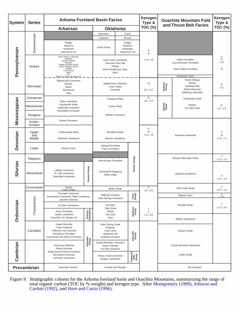
Figure 9. Stratigraphic column for the Arkoma foreland basin and Ouachita Mountains, summarizing the range oftotal organic carbon (TOC by % weight) and kerogen type. After Montgomery (1989), Johnson and Cardott (1992), and Horn and Curtis (1996).
1 2 3 4 5 6 7 8 9 10
-10000
-5000
0
5000
10000
15000
Rel
ativ
e S
trat
igra
ph
ic P
osi
tio
n (
ft)*
Mean Vitrinite Reflectance (% Ro)*
Estimated Woodford-Chattanooga top
Estimated Arbuckle top
Latimer County, OK
Sebastian County, OK
Yell County, AR
Logan County, AR
Faulkner County, AR
White County, AR
Figure 10. Depth vs. vitrinite reflectance profile for wells in Arkansas and Oklahoma. These profiles use the SpiroSandstone as a stratigraphic datum and indicate that thermal maturity of eastern Arkansas wells does notfollow the inferred west-to-east increase in maturity across the basin. After Horn and Curtis (1996) andHouseknecht et al. (1992).
Stratigraphic position relative to top of basal Atokan (Spiro/Orr) sandstone*
37
BLACK WARRIOR BASIN
GEOLOGIC SETTING
The Black Warrior Basin of Alabama and Mississippi is a foreland basin located in the major structural reentrantbetween the Appalachian fold-and-thrust belt to the southeast and the Ouachita fold-and-thrust belt to the southwest.Figure 11 shows the basin location and its major structural features. The northern margin of the basin is bounded bythe Nashville dome. The basin is shaped like a kite with its tail facing south, and has a surface area of about 35,000square miles. North to south, the basin extends about 190 miles, and the east-west width is about 220 miles. Theoverall sedimentary section in the province includes rocks of Paleozoic, Mesozoic and Cenozoic age that range inthickness from about 7,000 ft along the northern margin to about 31,000 ft in the depocenter located in easternMississippi (Ryder, 1994).
The geotectonic history of the basin includes 5 stages:
1) Late Precambrian-Early Cambrian rift with associated deposition of coarse clastics.
2) Middle Cambrian-Mississippian period of stable shelf deposition (7000 ft of shallow water carbonates)occurring on a passive continental margin.
3) Late Mississippian (Chester) transitional episode; early stages of continental collision, marine deltaicsedimentation and several major regressive-transgressive cycles.
4) Early-Late (?) Pennsylvanian time of maximum basin subsidence and synorogenic deposition related tomaturation of the Appalachian-Ouachita thrust belts. Following a brief period of barrier bar development,thick clastic wedges prograded from source areas along the south margin. Abundant coal bed development innorth-central portion of the basin.
5) Permian-Cretaceous erosion/non-deposition ending with Late Cretaceous marine incursion and depositioninto Early Tertiary shallow marine sediments (Mississippi Embayment).
Figure 12 shows a regional cross section of Mississippian strata across northwestern Alabama. The BlackWarrior basin was first downwarped in the Late Mississippian-Early Pennsylvanian and then subsequently filled byPennsylvanian shallow marine and terrestrial clastic material shed from rising highlands along its southern margin.No Permian or early Mesozoic deposits exist in the basin. Indications are that the Black Warrior was uplifted abovesea level in Latest Pennsylvanian-Early Mesozoic time (Montgomery, 1986). Continental break-up during theMesozoic resulted in the basin becoming downwarped to the southwest and eventually covered by the MississippiEmbayment marine transgressive episode (Mancini et al., 1983). Most of the basin and its thrust faulted margins areconcealed beneath Tertiary and Cretaceous rocks of the Gulf coastal plain and the Mississippi embayment.
38
HYDROCARBON PRODUCTION
The Black Warrior Basin is very prolific; the Lewis and Carter sandstones (Mississippian Chester Group) are themost productive (Figure 13). The depth to productive horizons ranges from 2,500 to 5,000 ft. Target intervals aregenerally shallower in Alabama than in Mississippi. The Carter Sandstone and other Mississippian productiveintervals extend into deeper basin regions (Bearden and Mancini, 1985). Remarkably high wildcat success rates (50%and more) and the shallow depths of the primary Late Paleozoic reservoir targets (less than 5,000 ft) keep explorationinterest high.
There are over 90 individual fields producing oil and gas from two principal productive trends. The northerlytrend produces principally from stratigraphic traps. The southern trend produces from structural and combinationtraps. One of most prolific fields is the unitized North Blowhorn Creek oil field (Lamar County, Alabama),completed in the Carter Sandstone which accounts for nearly 80% of the total oil produced in the entire basin(Montgomery, 1986).
There are multiple gas and gas-condensate reservoirs within the Late Paleozoic clastic units. Eleven individualreservoirs exist in the Mississippian Chester Group. At least 4 clastic units within the Lower PennsylvanianPottsville Formation produce gas (Figure 13). The clastic units consist of a series of prograding deltaicenvironments–delta front, bar finger, and distributary channel sands–separated by transgressive shales. Considerablelateral variability occurs in the reservoirs, and porosities range from 5% to 17%; permeabilities range from .01 to100 md. Thickness of individual reservoirs range from less than 10 ft to about 50 ft. The total sandstone thickness isless than 1,000 ft.
In addition, the deeper Cambro-Ordovician to Devonian carbonate units also produce in certain locations. To datethere have been over 40 deep structural tests (deeper than 10,000 feet) drilled on the Mississippi side of the basin.Many of these tests encountered significant gas shows from Mississippian and Pennsylvanian sandstone sections andfrom deeper Cambro-Ordovician, Silurian and Devonian rocks (Ericksen, 1993; Henderson, 1991). The lowersections need further exploration, as correlative zones to the west (Hunton and Ellenburger groups) are highlyproductive (Montgomery, 1986; Duchscherer, 1972; Devery, 1983).
Also, the Alabama part of the Black Warrior basin is one of the main centers of coalbed degasification in theU.S. Lower Pottsville rocks yield gas from depths of less than 2,700 ft, and estimated resources range from 20 to 35Tcf. To date fields in this area have yielded 0.9 Tcf.
BASIN CENTERED GAS EVIDENCE
Basin center gas potential exists in:
a. thick clastic wedges off the carbonate platform, in western Alabama and eastern Mississippi, including theleast-explored deeper depocenters in Mississippi, and
b. micritic and finely crystaline limestones and shale/siltstone intervals within Cambro-Ordovician formations.
The basin covers about 1500 square miles. Gas shows are numerous and widespread throughout the basin. Majorsource rocks are fairly organic, amorphous and herbceous-prone pro-delta shales with interbedded sandstone. Availablegeochemical data (including total organic carbon (TOC) thermal alteration index) suggest the basin is mature and theLate Paleozoic shales should be mainly gas prone (Bearden and Mancini, 1985). Henderson (1991) considers theTOCs of the black shales within the Stone River Limestone (Ordovician) favorable for hydrocarbon generation.Pennsylvanian sands in southern Pickens County, Alabama, contain large volumes of in-situ gas; low gas recoveriesindicate relatively low permeabilities (R.L. Ericksen, Office of Geology, State of Mississippi, 1999, pers.commun.) and low porosities (S.D. Champlin, Office of Geology, State of Mississippi, 1999, pers. commun.) ofthe rocks. Pressure gradients recorded to date are normal (Ericksen, 1999, pers. commun.; Champlin, 1999, pers.commun.).
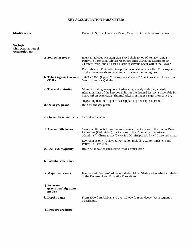
KEY ACCUMULATION PARAMETERS
Identification Eastern U.S., Black Warrior Basin, Cambrian through Pennsylvanian
Geologic Characterization of Accumulation:
a. Source/reservoir Interval includes Mississippian Floyd shale to top of Pennsylvanian Pottsville Formation. Eleven reservoirs exist within the Mississippian Chester Group, and at least 4 clastic reservoirs occur within the Lower
Pennsylvanian Pottsville Group. Carter sandstone and other Mississippian productive intervals are now known in deeper basin regions.
b. Total Organic Carbons (TOCs)
0.07%-2.36% (Upper Mississippian shales); 2.2% Ordovician Stones River Group (limestone) shales.
c. Thermal maturity Mixed including amorphous, herbaceous, woody and coaly material. Alteration state of the kerogen indicates the thermal history is favorable for hydrocarbon generation. Thermal Alteration Index ranges from 2 to 3+,
suggesting that the Upper Mississippian is primarily gas prone.d. Oil or gas prone Both oil and gas prone.
e. Overall basin maturity Considered mature.
f. Age and lithologies Cambrian through Lower Pennsylvanian: black shales of the Stones River Limestone (Ordovician); dark shales of the Conasauga Limestone (Cambrian); Chattanooga (Devonian/Mississippian), Floyd Shale including
Lewis sandstone; Packwood Formation including Carter sandstone and Pottsville Formation.
g. Rock extent/quality Basin-wide source and reservoir rock distribution
h. Potential reservoirs
i. Major traps/seals Interbedded Cambro-Ordovician shales; Floyd Shale and interbedded shales of the Packwood and Pottsville Formations
j. Petroleum generation/migration models
k. Depth ranges From 2500 ft in Alabama to over 10,000 ft in the deeper basin regions in Mississippi.
l. Pressure gradients

Production and Drilling Characteristics:
a. Important fields/reservoirs
The Lewis and Carter intervals are the most highly productive, especially in the north-central part of the basin (Lamar and Fayette counties, Alabama and Monroe, Clay, and Lowndes counties in Mississippi).
Grove Field, Carter sandstone 67 Bcf; Coal Fire Creek, Carter sandstone 19 Bcf, Lewis sandstone 6.9 Bcf, Fayette sandstone 2.5 Bcf; North Blowhorn Creek oil field—Carter sandstone accounts for nearly 80% of the total oil
produced in the entire basin (Montgomery, 1986), Carter sandstone 11.4 Bcf, Millerella 10.5 Bcf; Sanders Ss-one well (10,130-10,164 ft), over 12 Bcf in 10 years. Yellow Creek, Devonian chert production; Fairview Field,
Ordovician (Knox) dolomite—one well, 1.8 MMcf monthly.b. Cumulative production Cumulative production for Star Field (Lamar County, Alabama) producing
from a combination trap and numerous horizons:
Economic Characteristics:
a. Inert gas content
b. Recovery Low, in south Pickens County, Alabama.
c. Pipeline infrastructure Very good. There are numerous gas lines in the basin.
d. Exploration maturity relative to other basins
mature
Producing Formation(gas sands) (10/98)
Cumulative Oil(10/98)
Cumulative Gas(10/98)
Producing Wells
Carter (Miss) ...................... ............ 99,799 ............. .........19,218,189 .......... ................7
Chandler (Penn)................... ............ 27,543 ............. ............. 226,233 .......... ................0
Fayette (Penn)..................... ....................0 ............. ...............10,400 .......... ................1
Lewis (Miss) ...................... ............ 14,248 ............. .........13,146,529 .......... ................7
Lower Nason (Penn)............. ................ 372............. ............. 757,692 .......... ................1
Lower Millerella (Miss)........ ................ 797............. .......... 1,264,601 .......... ................0
Upper Nason (Penn)............. ................ 128............. ............. 187,983 .......... ................0
Carter Oil (Miss) ................. ............ 78,955 ............. ................. 6838 .......... ................1
Chandler Oil (Penn)............. ................ 865............. ...................... 0 .......... ................0
Total Cumulative Production . .......... 222,707 ............. .........34,818,492 .......... ............... 17

e. Sediment consolidation Consolidation/porosity reduction occurs with depth of burial.
f. Porosity/completion problems
Most wells are shallow and problem-free. Low porosity occurs in south Pickens County, Alabama (S.D. Champlin and R.L. Ericksen, Office of Geology, State of Mississippi, 1999, personal communication).
g. Permeability 0.01 to 100 md
h. Porosity 5-17%
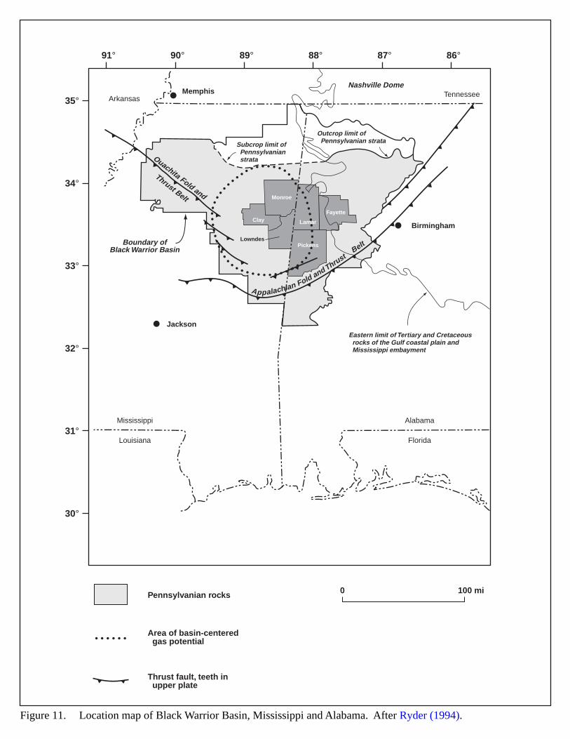
Boundary ofBlack Warrior Basin
Lamar
Fayette
Pickens
Monroe
Clay
Lowndes
91°
35°
34°
33°
32°
31°
30°
90° 89° 88° 87° 86°
Jackson
Birmingham
Memphis
Louisiana
Mississippi
Florida
Alabama
TennesseeArkansas
Eastern limit of Tertiary and Cretaceous rocks of the Gulf coastal plain and Mississippi embayment
Subcrop limit of Pennsylvanian strata
Outcrop limit of Pennsylvanian strata
Nashville Dome
Ouachita Fold and
Thrust Belt
Appalachian Fold and ThrustBelt
0 100 miPennsylvanian rocks
Area of basin-centered gas potential
Thrust fault, teeth in upper plate
Figure 11. Location map of Black Warrior Basin, Mississippi and Alabama. After Ryder (1994).
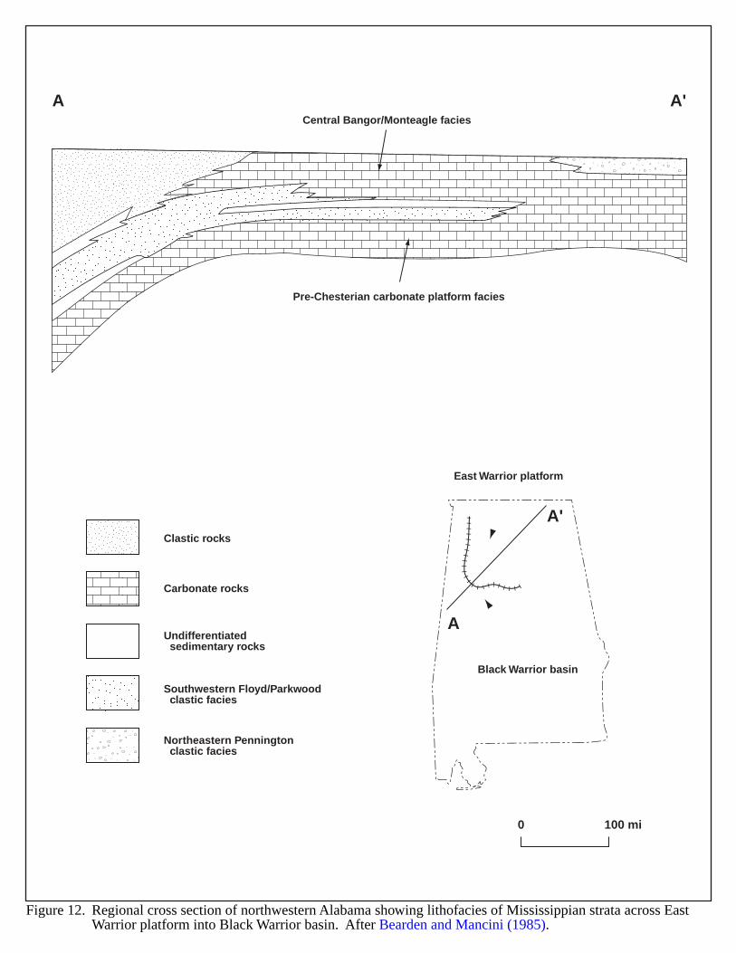
0 100 mi
A
A'
East Warrior platform
Black Warrior basin
A A'
Pre-Chesterian carbonate platform facies
Central Bangor/Monteagle facies
Clastic rocks
Southwestern Floyd/Parkwood clastic facies
Northeastern Pennington clastic facies
Carbonate rocks
Undifferentiated sedimentary rocks
Figure 12. Regional cross section of northwestern Alabama showing lithofacies of Mississippian strata across EastWarrior platform into Black Warrior basin. After Bearden and Mancini (1985).
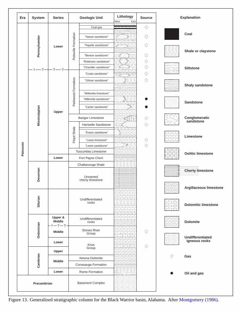
Era System Series Geologic Unit LithologyWest East
Source
Coal gas
"Nason sandstone"
"Fayette sandstone"
"Benton sandstone"
"Robinson sandstone"
"Chandler sandstone"
"Coats sandstone"
"Gilmer sandstone"
"Millerella sandstone"
"Carter sandstone"
"Evans sandstone"
Bangor Limestone
Tuscumbia Limestone
Fort Payne Chert
Chattanooga Shale
Unnamedcherty limestone
Undifferentiatedrocks
Undifferentiatedrocks
Stones RiverGroup
KnoxGroup
Ketona Dolomite
Conasauga Formation
Rome Formation
Basement Complex
Hartselle Sandstone
"Millerella limestone"
"Lewis sandstone"
"Lewis limestone"
Pot
tsvi
lle F
orm
atio
n
Pen
nsy
lvan
ian
Lower
Mis
siss
ipp
ian
Pal
eozo
ic
Precambrian
Dev
on
ian
Silu
rian
Ord
ovic
ian
Cam
bri
an
Upper
Lower
Lower
Middle
Upper &Middle
Lower
Middle
Upper
Par
kwoo
d F
orm
atio
nF
loyd
Sha
le
? ??
? ? ??
Coal
Shale or claystone
Siltstone
Shaly sandstone
Sandstone
Conglomeratic sandstone
Limestone
Oolitic limestone
Cherty limestone
Argillaceous limestone
Dolomitic limestone
Dolomite
Undifferentiated igneous rocks
Gas
Oil and gas
Explanation
Figure 13. Generalized stratigraphic column for the Black Warrior basin, Alabama. After Montgomery (1986).
45
CENTRAL ALASKA BASINS
GEOLOGIC SETTING
The interior basins of Alaska cover a broad area extending from the Canadian border on the east to the BeringSea on the west. There are a number of basins (Kandik, Yukon-Koyukuk, Kuskokwim, Bethel, Nenana, Tanana) thathave been included in the Central Alaska Province of recent USGS assessments (Figure 14). The Central AlaskaProvince covers about 300,000 square miles between the Brooks Range on the north and the Alaska Range on thesouth (Stanley, 1996).
Central Alaskan geology is complex and varied, characterized by fold and thrust belts. Diverse crustal terranesformed along the ancestral North American cratonic margin, and structural deformation in this region is often severe(Magoon, 1993). Much of central Alaska experienced deformation in late Cretaceous to early Tertiary time (Stanley,1996). The basins include areas of complexly deformed and locally metamorphosed flysch deposits underlying thickCenozoic nonmarine sediments (Kirschner, 1988).
Three types of basins occur within the central Alaska (Magoon and Kirschner, 1990):
1. Segments of the Cordilleran fold and thrust belt. The Kandik basin represents such a segment, and ischaracterized by thrust-faulted anticlines that largely affected clastic and carbonate reservoirs of Paleozoic toTertiary age. The right-lateral Tintina fault truncates the basin on the southwest (Magoon, 1993).
2. Mesozoic flysch basins. The flysch belts and flysch terranes represent volcanic-plutonic arc-basin deposits(Magoon and Kirschner, 1990). The flysch belts of the Yukon-Koyukuk, Kuskokwim, and Bethel basinsconsist of deep marine turbidite sandstones and shales, shallow marine alluvial fans, and coal bearing deltaicand fluvial facies (Stanley, 1996).
3. Cenozoic basins. These consist of undeformed to moderately deformed strata reflecting a distinctive gravitylow (Magoon and Kirschner, 1990). They include a thick sequence of Tertiary and Quaternary rocksoverlying Precambrian to Mesozoic igneous and metamorphic rocks (Stanley, 1996).
The stratigraphic section consists of a sequence of Precambrian rocks overlain by a succession of Paleozoic toCenozoic sediments. Figure 15 illustrates the generalized stratigraphic nomenclature common across the CentralAlaska province. The Kandik basin contains the thickest stratigraphic section, with Proterozoic to Cenozoic rockshaving a cumulative thickness greater than 40,000 feet (Hite, 1997). The Paleozoic section is approximately 15,000feet thick. An unconformity at the top of the McCann Hill chert separates the Lower Paleozoic continental marginsediments from the overlying Upper Devonian to Permian foreland basin sequence (Hite, 1997). The Nenana andMiddle Tanana basins contain an assemblage of sedimentary rocks from the Middle and Lower Miocene to PlioceneUsibelli group, which nonconformably overlie Precambrian and Paleozoic rocks (Stanley et al., 1990). The Betheland Yukon-Koyukuk basins contain thick, widely distributed Cretaceous strata, including a large volume of volcanicrocks. Basal andesitic rocks are overlain by about 10,000 feet of graywacke and mudstones of lower CretaceousAlbian age (Patton, 1971).
46
HYDROCARBON POTENTIAL
There is no known hydrocarbon production in the basins of central Alaska. Drilling is very sparse, but the fewwells drilled have encountered numerous shows of oil and gas. Other similar regions in Alaska are richly productive.Exploration efforts began in the Central Alaska basins as a result of hydrocarbon discoveries on the North Slope.Cretaceous strata similar to those on the North Slope exist beneath alluvial lowlands. Operators drilled a 12,000 footwell near Nulato on the Yukon River, and a 15,000 foot hole in the Yukon-Koyukuk basin. Neither wells hadcommercial shows (Patton, 1971).
The sedimentary sequences in central Alaskan basins may provide favorable settings for basin-centeredhydrocarbon accumulations. Reservoir rocks in the Tertiary basins of central Alaska may be similar to the reservoirsin the producing fields of the Cook Inlet-Beluga-Sterling play (Magoon and Kirschner, 1990).
The Kandik and Middle Tanana basins appear to have the greatest hydrocarbon potential (Grether and Morgan,1988). The Kandik and Yukon Flats basins may contain significant reserves of oil and gas within a 40,000 feet thicksedimentary package.
Three exploratory wells have been drilled in the Kandik basin. These wells encountered some porosity andbitumen in Devonian carbonates (DiBona and Kirschner, 1984). The Triassic Glenn Shale in the Kandik basin is anorganic equivalent to the Shublik Formation of the North Slope and may have generated as much as 1.5 billionbarrels of oil per cubic mile of sediment (Hite, 1997). In the Middle Tanana basin, only two exploratory wells havebeen drilled–the Unocal Nanana No. 1, and the ARCO Totek Hills No. 1. Both wells penetrated a thick Tertiary coal-bearing section of the Usibelli Group and terminated in metamorphic basement (Smith, 1995). The ARCO TotekHills well was drilled on the basin flank and passed through 3,015 feet of Tertiary rocks. The sandstones averaged17% porosity and 11 md permeability. The claystones contained Type II kerogen and indicate some oil potential(Grether and Morgan, 1988). Smith (1995) suggests that Tertiary coals of the Yukon Flats, Nenana, and MiddleTanana basins provide opportunities for commercial gas production.
Three hypothetical petroleum systems occur in central Alaska (Stanley, 1996):
1. Cenozoic gas. This system includes organically rich source rocks and has a potential for nonassociated gasin undeformed to moderately deformed strata.
2. Mesozoic gas. This system lies within sequences of flysch deposits, particularly in the Yukon-Koyukuk andKuskokwim basins where various authors have reported lateral facies changes from deep marine turbidites todeltaic and shallow marine sediments (Patton, 1971; Nilsen, 1989; and Box and Elder, 1992). These facieschanges indicate possible stratigraphic traps and may contain a basin-centered gas accumulation. TheBenedum Nulato Unit No. 1 well drilled in the Koyukuk basin penetrated gas-prone kerogens in theCretaceous section (Stanley, 1996).
3. Paleozoic oil. This system includes Ordovician, Silurian and Devonian graptolitic shales similar to onesfound in basins elsewhere in North America, the Middle East and North Africa that contain oil-pronekerogen (Klemme and Ulmishek, 1991). These rocks may be potential sources for oil, and if heatedsufficiently, a source for natural gas as well.
47
EVIDENCE FOR BASIN-CENTERED GAS
In the central Alaska basins, basin-centered hydrocarbon accumulations potentially exist within thick fluvial andlacustrine units: sandstones, conglomeratic sandstones, turbidites, shales, siltstones and coals. Available source andmaturation data (TOC, TAI, Ro, and Tmax) indicate that the basins are marginally mature to overmature (Stanley etal., 1990; Smith, 1995. However, Stanley (1996) believes that the late Cretaceous and Tertiary source rocks arethermally immature.
The Kandik and Middle Tanana basins appear to have the most potential for basin-centered gas accumulation. Inthe Middle Tanana basin, Stanley et al. 1990 estimate the top of the oil window (Ro = 0.6) occurs at depthsexceeding 4,500 ft. Vitrinite reflectance values in the Kandik basin fall within the gas generation window(Figure 16). In the Middle Tanana basin, data from the ARCO Totek Hills No. 1 well indicates the presence ofTypes II and III kerogen, indicating the Usibelli Group strata may be oil and gas-prone. Based on present informationregarding thermal maturity, wells drilled in the deeper parts of the central Alaska basins may encounter strata buriedbelow the top of the oil window, and therefore, potentially encounter basin-centered hydrocarbon accumulations.
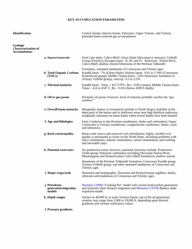
KEY ACCUMULATION PARAMETERS
Identification Central Alaska, Interior basins, Paleozoic, Upper Triassic, and Tertiary potential basin-centered gas accumulations
Geologic Characterization of Accumulation:
a. Source/reservoir Ford Lake shale, Calico Bluff, Glenn Shale (Devonian to Jurassic), Usibelli Group (Tertiary); Kerogen types: II, III, and IV. Reservoir: Nation River, Calico Bluff, shallow marine limestones of the Permian Tahkandit
Formation, unnamed sandstones of Cretaceous and Tertiary ages.b. Total Organic Carbons
(TOCs)Kandik basin: 7% (Glenn Shale); Holitna basin: 0.61 to 1.59% (Cretaceous Kuskokwim group); Middle Tanana basin: 3.6% (Sanctuary formation of Tertiary Usibelli group), outcrop: 0.5 to 3.5%.
c. Thermal maturity Kandik basin: Tmax = 427-579°C, Ro = 0.8% (mean); Middle Tanana basin: Tmax = 414 to 434° C, Ro = 0.6% (below 4500 ft depth).
d. Oil or gas prone Primarily oil prone; however, level of maturity probably reaches the "gas window."
e. Overall basin maturity Marginally mature to overmature (similar to North Slope), probably in the deep parts of the basins and in shallower areas near high heatflow pathways; marginally immature on basin flanks where burial depths have been limited.
f. Age and lithologies Early Cambrian to late Permian (sandstones, shales and carbonates), Upper Cretaceous to Tertiary (sandstones, conglomeratic sandstones, shales, coals and siltstones).
g. Rock extent/quality Basin-wide source and reservoir rock distribution; highly variable rock quality is anticipated as exists on the North Slope, including problems with silica cementation, siderite cementation, calcite cementation, and swelling and moveable clays.
h. Potential reservoirs No production exists; however, potential reservoirs include Proterozoic Tindir group; Paleozoic carbonates (including Devonian Nation River, Mississippian and Pennsylvanian Calico Bluff formation); shallow marine
limestones of the Permian Tahkandit formation; Cretaceous Kandik group; Tertiary Usibelli group; and other unnamed sandstones of Cretaceous and Tertiary ages.
i. Major traps/seals Structural and stratigraphic, Devonian and Pennsylvanian argillites, shales, siltstones and mudstones of Cretaceous and Tertiary ages.
j. Petroleum generation/migration models
Weimer's (1996) "Cooking Pot" model with current hydrocarbon generation and relatively short distance migration and Meissner's (1978) Bakken shale expulsion model.
k. Depth ranges Surface to 40,000 ft, in some Tertiary basins, top of the oil generation window may range from 5,000 to 10,000 ft, depending upon thermal gradients and vitrinite reflectance values.
l. Pressure gradients

Production and Drilling Characteristics:
a. Important fields/reservoirs
b. Cumulative production
Economic Characteristics:
a. Inert gas content
b. Recovery
c. Pipeline infrastructure Non-existent, except for the trans-Alaska oil pipeline.
d. Exploration maturity relative to other basins
Immature
e. Sediment consolidation Moderate or better consolidation.
f. Porosity/completion problems
Unknown due to no known completions.
g. Permeability
h. Porosity
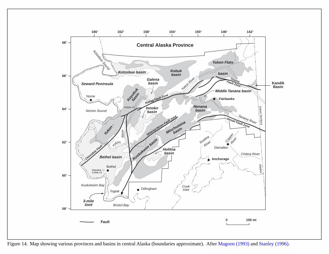
68°
66°
64°
62°
60°
58°
166° 162° 158° 154° 150° 146° 142°
Susitna
River Cop
per
River
Nome
Bethel
TogiakDillingham
Bristol Bay
CookInlet
Tanana River
Yuko
n Rive
r
Chitina River
Kuskokwim Bay
Kotzebue Sound
AnchorageBethel basin Kuskokwim
basin
3-milelimit
Kobukbasin
Kotzebue basin
Yukon Flats
basin
Nenanabasin
Middle Tanana basin
Seward Peninsula
Minchumina
basin
Yuko
n -
Fairbanks
Glenallen
Alaska
Yukon Territory
Central Alaska Province
Galenabasin
Innokobasin
Holitnabasin
KandikBasin
Norton Sound
Yukon
Riv
er
Chiroskey
Fault
Denali Fault Zone
Iditarod-Nixon Fault Z
one
Kaltag Fault Zone
TintinaFault Zone
NapatukCreek #1
Nulato #1
Koyuk
ukba
sin
0 100 mi
Figure 14. Map showing various provinces and basins in central Alaska (boundaries approximate). After Magoon (1993) and Stanley (1996).
Fault
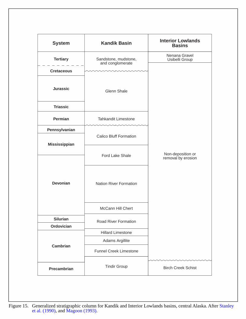
System
Tertiary Sandstone, mudstone,and conglomerate
Nenana GravelUsibelli Group
Non-deposition orremoval by erosion
Birch Creek Schist
Glenn Shale
Tahkandit Limestone
Calico Bluff Formation
Ford Lake Shale
Nation River Formation
McCann Hill Chert
Road River Formation
Hillard Limestone
Adams Argillite
Funnel Creek Limestone
Tindir Group
Cretaceous
Jurassic
Triassic
Permian
Pennsylvanian
Mississippian
Devonian
Silurian
Ordovician
Cambrian
Precambrian
Kandik Basin Interior LowlandsBasins
Figure 15. Generalized stratigraphic column for Kandik and Interior Lowlands basins, central Alaska. After Stanleyet al. (1990), and Magoon (1993).
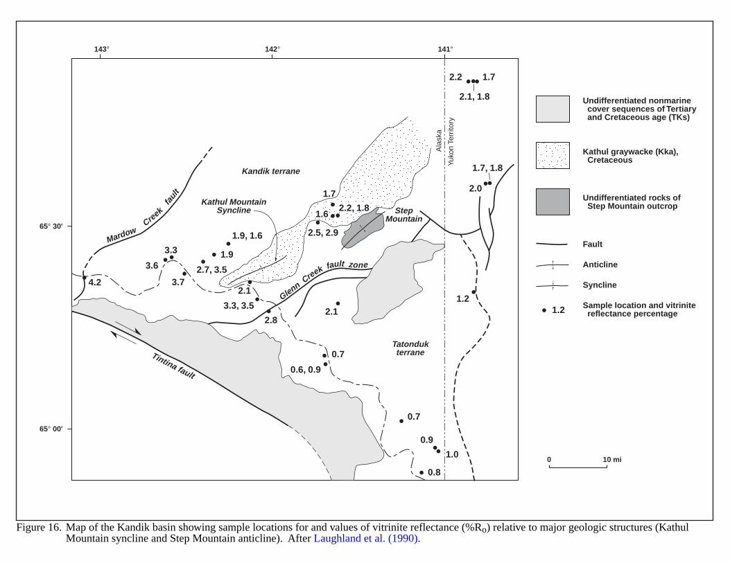
143° 142° 141°
65° 30'
65° 00'A
lask
a
Yuko
n Te
rrito
ry
GlennCreek fault zone
MardowCre
ek
faul
t
Kandik terrane
StepMountain
Kathul MountainSyncline
TatondukterraneTintina fault
4.2
3.3 1.9
2.82.1
0.7
0.7
0.8
1.0
0.9
1.7
2.1
3.3, 3.5
2.5, 2.9
0.6, 0.9
2.7, 3.5
2.2, 1.8
1.7, 1.8
2.1, 1.8
1.9, 1.6
3.6
3.7
1.6
2.0
2.2 1.7
1.2
0 10 mi
Undifferentiated nonmarine cover sequences of Tertiary and Cretaceous age (TKs)
Kathul graywacke (Kka), Cretaceous
Undifferentiated rocks of Step Mountain outcrop
Fault
Anticline
Syncline
Sample location and vitrinite reflectance percentage
Figure 16. Map of the Kandik basin showing sample locations for and values of vitrinite reflectance (%Ro) relative to major geologic structures (KathulMountain syncline and Step Mountain anticline). After Laughland et al. (1990).
1.2
53
CHUAR GROUP (PRECAMBRIAN PARADOX BASIN)
GEOLOGIC SETTING
The Late Proterozoic Chuar Group extends from northern Arizona into southwestern Wyoming. Figure 17depicts a map of the regional extent and outcrop locations of the Chuar rocks. Exposures in the Grand Canyon reacha thickness of approximately 5,370 ft, and the rocks consist of organic-rich gray-black shale and siltstone interbeddedwith sandstones and cryptalgal and stromatolitic carbonates (Reynolds et al., 1988; Palacas, 1992). The Chuar Groupcontains the Galeros Formation and the overlying Kwagunt Formation (Figure 18). The lithologies indicate variouscyclical depositional environments, including a sediment-starved basin rich in organic material, coastal and alluvialplains, paludal swamp, and nearshore marine. Deposition of the Chuar Group occurred on a marine embayment onthe passive edge of a continent (Reynolds et al., 1988).
HYDROCARBON PRODUCTION
There have been some exploratory wells that penetrated the Chuar, but no production. Shows and tests of thissection are rare. Geochemical analyses of outcrop samples from the Walcott Member of the Kwagunt Formationindicate good to excellent source-rock potential and thermal maturity for oil generation. Tmax values range from 424to 452 °C. Total organic carbon values (TOCs) average ~ 3.0 %, with highs ranging from 8.0 to 10.0 %. Samplesfrom the upper part of the Walcott yielded higher values than those from the lower part (Palacas, 1992). Theunderlying Galeros Formation shows lower TOC values and appears thermally overmature, but still might be withinthe window for gas generation.
EVIDENCE FOR BASIN-CENTERED GAS
The Walcott Member demonstrates good source-rock potential and may contain sandstones with good reservoirquality. Stratigraphic and conventional structural prospects may exist if the source rock is continuous.
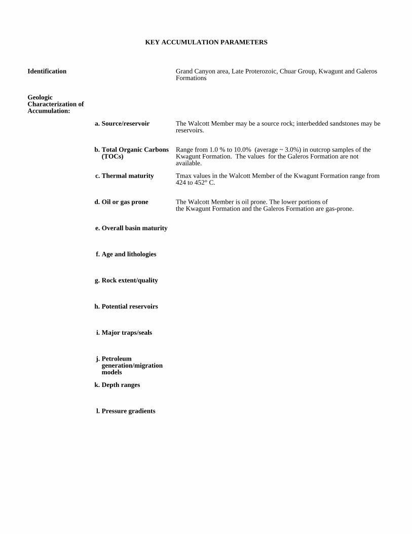
KEY ACCUMULATION PARAMETERS
Identification Grand Canyon area, Late Proterozoic, Chuar Group, Kwagunt and Galeros Formations
Geologic Characterization of Accumulation:
a. Source/reservoir The Walcott Member may be a source rock; interbedded sandstones may be reservoirs.
b. Total Organic Carbons (TOCs)
Range from 1.0 % to 10.0% (average ~ 3.0%) in outcrop samples of the Kwagunt Formation. The values for the Galeros Formation are not available.
c. Thermal maturity Tmax values in the Walcott Member of the Kwagunt Formation range from 424 to 452° C.
d. Oil or gas prone The Walcott Member is oil prone. The lower portions ofthe Kwagunt Formation and the Galeros Formation are gas-prone.
e. Overall basin maturity
f. Age and lithologies
g. Rock extent/quality
h. Potential reservoirs
i. Major traps/seals
j. Petroleum generation/migration models
k. Depth ranges
l. Pressure gradients

Production and Drilling Characteristics:
a. Important fields/reservoirs
b. Cumulative production
Economic Characteristics:
a. Inert gas content
b. Recovery
c. Pipeline infrastructure
d. Exploration maturity relative to other basins
Because of the virtually untested nature of the deposit, it is immature.
e. Sediment consolidation
f. Porosity/completion problems
g. Permeability
h. Porosity
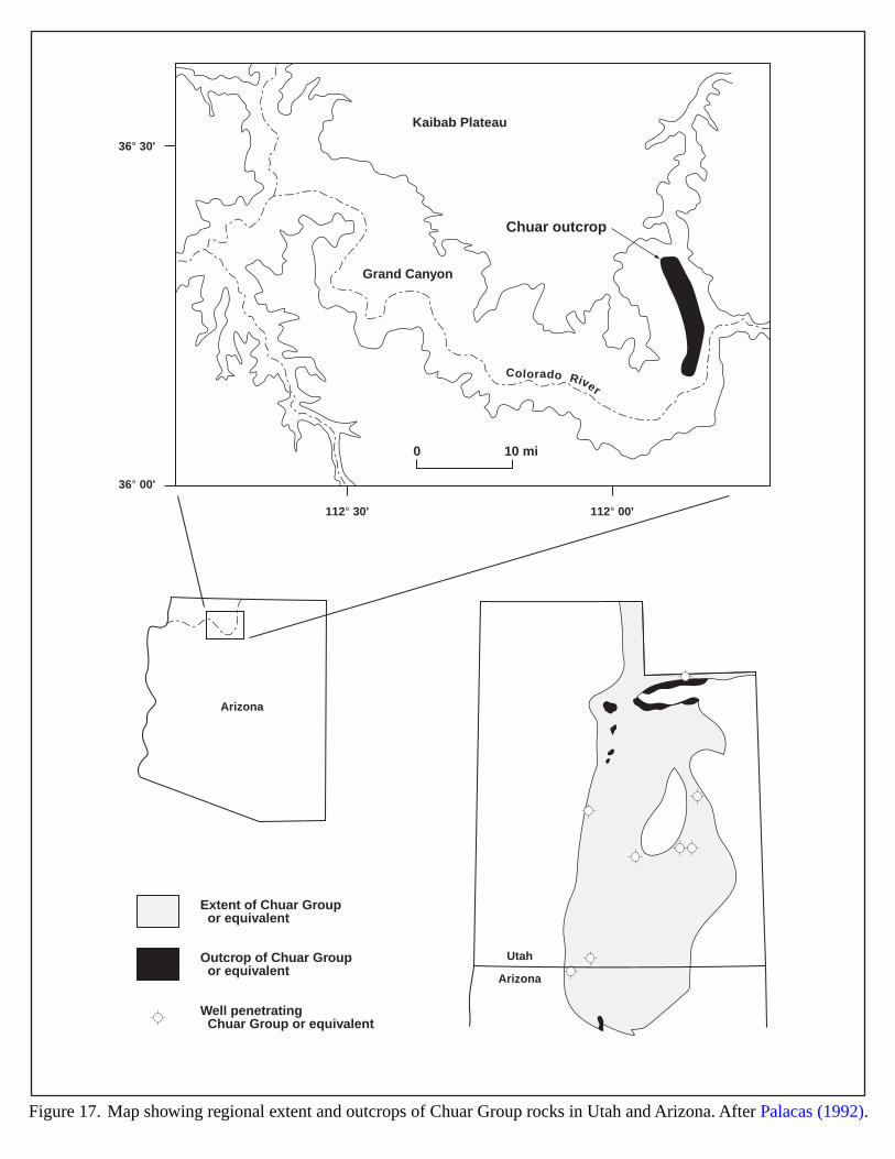
36° 30'
36° 00'
112° 30' 112° 00'
Kaibab Plateau
Grand Canyon
Chuar outcrop
Colorado Rive r
Arizona
Utah
Arizona
0 10 mi
Extent of Chuar Group or equivalent
Outcrop of Chuar Group or equivalent
Well penetrating Chuar Group or equivalent
Figure 17. Map showing regional extent and outcrops of Chuar Group rocks in Utah and Arizona. After Palacas (1992).
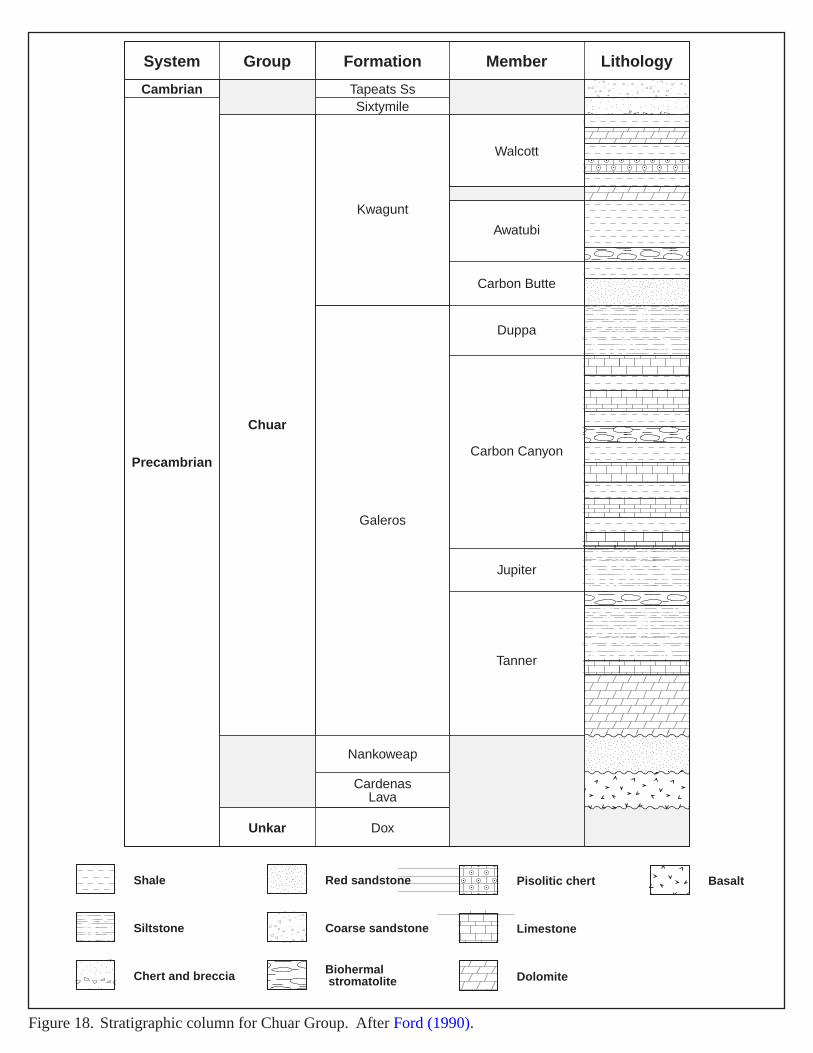
LithologyMember
Walcott
Awatubi
Carbon Butte
Duppa
Carbon Canyon
Jupiter
Tanner
FormationGroup
Chuar
Unkar Dox
System
Cambrian
Precambrian
Tapeats SsSixtymile
Kwagunt
Galeros
Nankoweap
CardenasLava
Figure 18. Stratigraphic column for Chuar Group. After Ford (1990).
Shale
Siltstone
Chert and breccia
Pisolitic chert Basalt
Limestone
Dolomite
Red sandstone
Coarse sandstone
Biohermal stromatolite
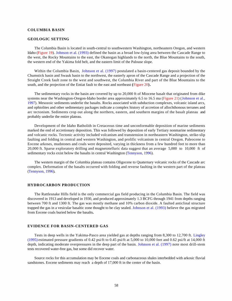
58
COLUMBIA BASIN
GEOLOGIC SETTING
The Columbia Basin is located in south-central to southwestern Washington, northeastern Oregon, and westernIdaho (Figure 19). Johnson et al. (1993) defined the basin as a broad low-lying area between the Cascade Range tothe west, the Rocky Mountains to the east, the Okanogan highlands to the north, the Blue Mountains to the south,the western end of the Yakima fold belt, and the eastern limit of the Palouse slope.
Within the Columbia Basin, Johnson et al. (1997) postulated a basin-centered gas deposit bounded by theChumstick basin and Swauk basin to the northwest, the easterly apron of the Cascade Range and a projection of theStraight Creek fault zone to the west and southwest, the Columbia River and part of the Blue Mountains to thesouth, and the projection of the Entiat fault to the east and northeast (Figure 20) .
The sedimentary rocks in the basin are covered by up to 20,000 ft of Miocene basalt that originated from dikesystems near the Washington-Oregon-Idaho border area approximately 6.5 to 16.5 ma (Figure 21) (Johnson et al.,1997). Mesozoic sediments underlie the basalts. Rocks associated with subduction complexes, volcanic island arcs,and ophiolites and other sedimentary packages indicate a complex history of accretion of allochthonous terranes andarc tectonism. Sediments crop out along the northern, eastern, and southern margins of the basalt plateau andprobably underlie the entire plateau.
Development of the Idaho Batholith in Cretaceous time and unconformable deposition of marine sedimentsmarked the end of accretionary deposition. This was followed by deposition of early Tertiary nonmarine sedimentaryand volcanic rocks. Tectonic activity included volcanism and transtension in northeastern Washington, strike-slipfaulting and folding in central and western Washington, and prolific volcanism in central Oregon. Paleocene toEocene arkoses, mudstones and coals were deposited, varying in thickness from a few hundred feet to more than20,000 ft. Sparse exploratory drilling and magnetotelluric data suggest that an average 5,000 to 10,000 ft ofsedimentary rocks exist below the basalts in central Washington (Tennyson, 1996).
The western margin of the Columbia plateau contains Oligocene to Quaternary volcanic rocks of the Cascade arccomplex. Deformation of the basalts occurred with folding and reverse faulting in the western part of the plateau(Tennyson, 1996).
HYDROCARBON PRODUCTION
The Rattlesnake Hills field is the only commercial gas field producing in the Columbia Basin. The field wasdiscovered in 1913 and developed in 1930, and produced approximately 1.3 BCFG through 1941 from depths rangingbetween 700 ft and 1300 ft. The gas was mostly methane and 10% carbon dioxide. A faulted anticlinal structuretrapped the gas in a vesicular basaltic zone thought to be clay sealed. Johnson et al. (1993) believe the gas migratedfrom Eocene coals buried below the basalts.
EVIDENCE FOR BASIN-CENTERED GAS
Tests in deep wells in the Yakima-Pasco area yielded gas at depths ranging from 8,300 to 12,700 ft. Lingley(1995) estimated pressure gradients of 0.42 psi/ft to 0.45 psi/ft at 5,000 to 10,000 feet and 0.62 psi/ft at 14,000 ftdepth, indicating moderate overpressures in the deep part of the basin. Johnson et al. (1997) note most drill-stemtests recovered water-free gas, but some did recover water.
Source rocks for this accumulation may be Eocene coals and carbonaceous shales interbedded with arkosic fluvialsandstones. Eocene sediments may reach a depth of 17,000 ft in the center of the basin.
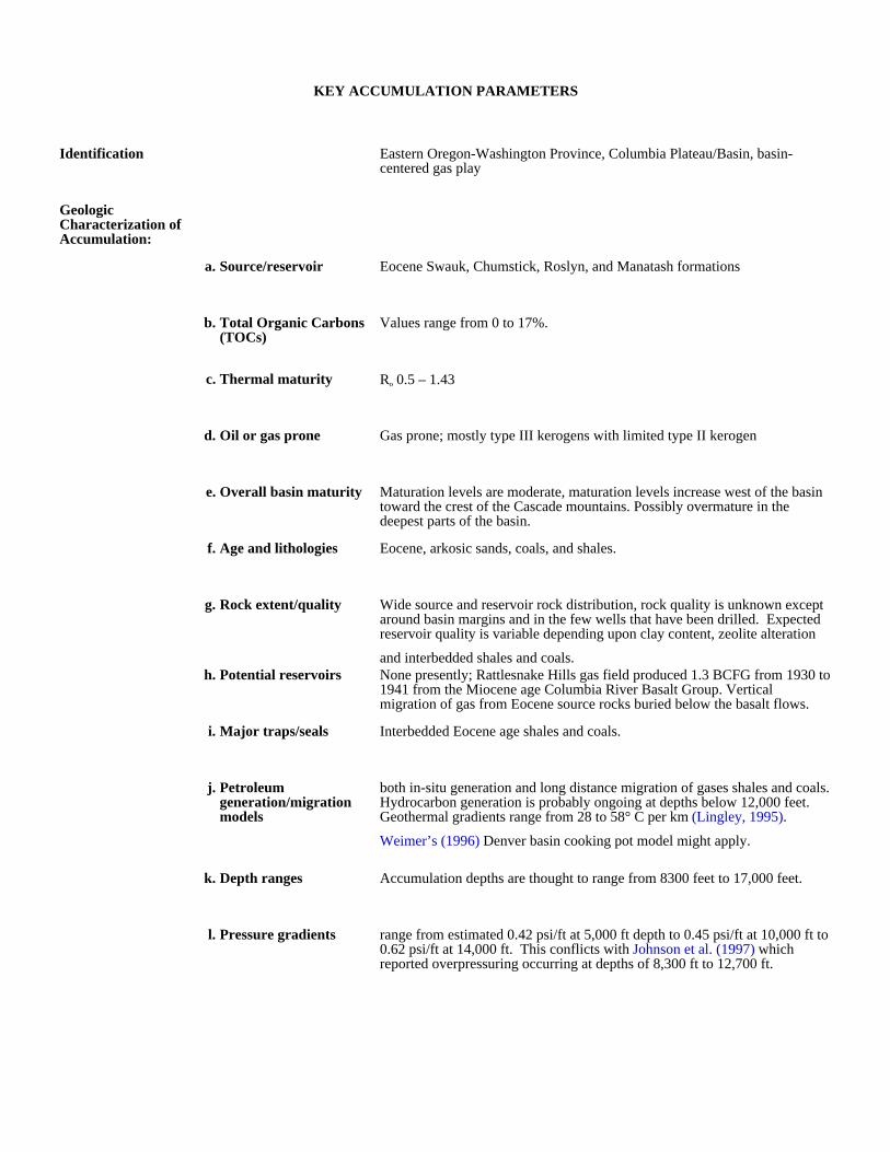
KEY ACCUMULATION PARAMETERS
Identification Eastern Oregon-Washington Province, Columbia Plateau/Basin, basin-centered gas play
Geologic Characterization of Accumulation:
a. Source/reservoir Eocene Swauk, Chumstick, Roslyn, and Manatash formations
b. Total Organic Carbons (TOCs)
Values range from 0 to 17%.
c. Thermal maturity Ro 0.5 – 1.43
d. Oil or gas prone Gas prone; mostly type III kerogens with limited type II kerogen
e. Overall basin maturity Maturation levels are moderate, maturation levels increase west of the basin toward the crest of the Cascade mountains. Possibly overmature in the deepest parts of the basin.
f. Age and lithologies Eocene, arkosic sands, coals, and shales.
g. Rock extent/quality Wide source and reservoir rock distribution, rock quality is unknown except around basin margins and in the few wells that have been drilled. Expected reservoir quality is variable depending upon clay content, zeolite alteration
and interbedded shales and coals.h. Potential reservoirs None presently; Rattlesnake Hills gas field produced 1.3 BCFG from 1930 to
1941 from the Miocene age Columbia River Basalt Group. Vertical migration of gas from Eocene source rocks buried below the basalt flows.
i. Major traps/seals Interbedded Eocene age shales and coals.
j. Petroleum generation/migration models
both in-situ generation and long distance migration of gases shales and coals. Hydrocarbon generation is probably ongoing at depths below 12,000 feet. Geothermal gradients range from 28 to 58° C per km (Lingley, 1995).
Weimer’s (1996) Denver basin cooking pot model might apply.
k. Depth ranges Accumulation depths are thought to range from 8300 feet to 17,000 feet.
l. Pressure gradients range from estimated 0.42 psi/ft at 5,000 ft depth to 0.45 psi/ft at 10,000 ft to 0.62 psi/ft at 14,000 ft. This conflicts with Johnson et al. (1997) which reported overpressuring occurring at depths of 8,300 ft to 12,700 ft.
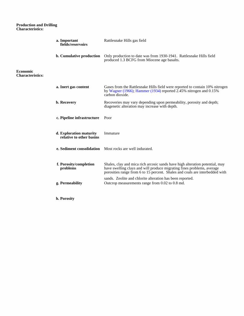
Production and Drilling Characteristics:
a. Important fields/reservoirs
Rattlesnake Hills gas field
b. Cumulative production Only production to date was from 1930-1941. Rattlesnake Hills field produced 1.3 BCFG from Miocene age basalts.
Economic Characteristics:
a. Inert gas content Gases from the Rattlesnake Hills field were reported to contain 10% nitrogen by Wagner (1966); Hammer (1934) reported 2.45% nitrogen and 0.15% carbon dioxide.
b. Recovery Recoveries may vary depending upon permeability, porosity and depth; diagenetic alteration may increase with depth.
c. Pipeline infrastructure Poor
d. Exploration maturity relative to other basins
Immature
e. Sediment consolidation Most rocks are well indurated.
f. Porosity/completion problems
Shales, clay and mica rich arcosic sands have high alteration potential, may have swelling clays and will produce migrating fines problems, average porosities range from 6 to 15 percent. Shales and coals are interbedded with
sands. Zeolite and chlorite alteration has been reported.g. Permeability Outcrop measurements range from 0.02 to 0.8 md.
h. Porosity
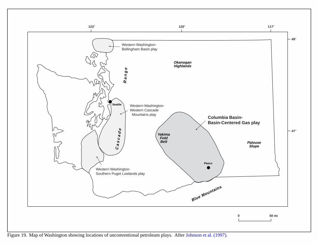
123° 120° 117°
49°
47°
0 50 mi
Western Washington-Bellingham Basin play
Columbia Basin-Basin-Centered Gas play
Western Washington-Western Cascade Mountains play
Western Washington-Southern Puget Lowlands play
Blue Mountains
Ca
sc
ad
eR
an
ge
YakimaFoldBelt
OkanoganHighlands
PalouseSlope
Pasco
Seattle
Figure 19. Map of Washington showing locations of unconventional petroleum plays. After Johnson et al. (1997).
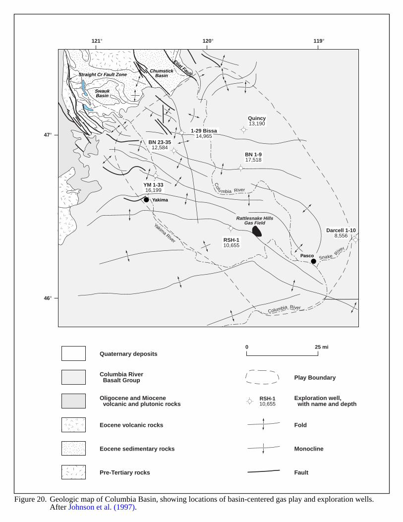
46°
47°
121° 120° 119°
SwaukBasin
Straight Cr Fault ZoneChumstick
Basin
Etiat Fault
Darcell 1-108,556
1-29 Bissa14,965
BN 23-3512,584
RSH-110,655
BN 1-917,518
Quincy13,190
YM 1-3316,199
Yakima River
Columbia River
Snake Rive
r
Colu mbia River
Rattlesnake HillsGas Field
Pasco
Yakima
Quaternary deposits
Eocene volcanic rocks
Eocene sedimentary rocks
Pre-Tertiary rocks
Columbia River Basalt Group
Oligocene and Miocene volcanic and plutonic rocks
0 25 mi
Fold
Monocline
Fault
Play Boundary
Exploration well, with name and depth
RSH-110,655
Figure 20. Geologic map of Columbia Basin, showing locations of basin-centered gas play and exploration wells.After Johnson et al. (1997).
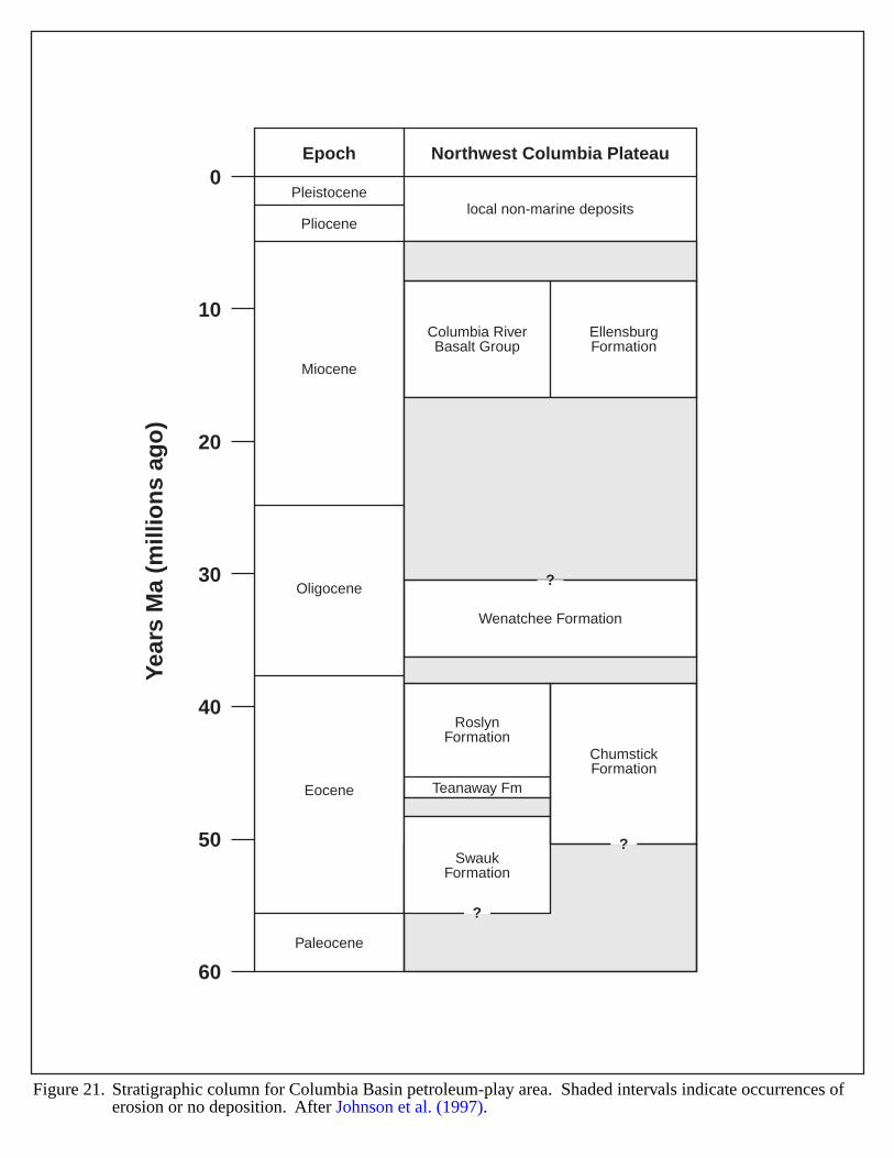
0
10
20
30
40
50
60
Year
s M
a (m
illio
ns
ago
)Epoch
Pleistocenelocal non-marine deposits
Pliocene
Miocene
Oligocene
Eocene
Paleocene
RoslynFormation
ChumstickFormation
Teanaway Fm
SwaukFormation
Wenatchee Formation
Columbia RiverBasalt Group
EllensburgFormation
Northwest Columbia Plateau
?
?
?
Figure 21. Stratigraphic column for Columbia Basin petroleum-play area. Shaded intervals indicate occurrences oferosion or no deposition. After Johnson et al. (1997).
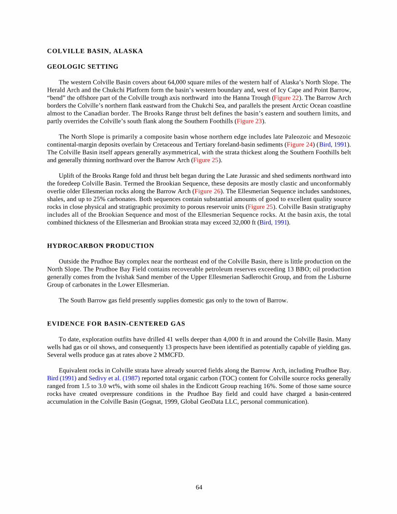
64
COLVILLE BASIN, ALASKA
GEOLOGIC SETTING
The western Colville Basin covers about 64,000 square miles of the western half of Alaska’s North Slope. TheHerald Arch and the Chukchi Platform form the basin’s western boundary and, west of Icy Cape and Point Barrow,“bend” the offshore part of the Colville trough axis northward into the Hanna Trough (Figure 22). The Barrow Archborders the Colville’s northern flank eastward from the Chukchi Sea, and parallels the present Arctic Ocean coastlinealmost to the Canadian border. The Brooks Range thrust belt defines the basin’s eastern and southern limits, andpartly overrides the Colville’s south flank along the Southern Foothills (Figure 23).
The North Slope is primarily a composite basin whose northern edge includes late Paleozoic and Mesozoiccontinental-margin deposits overlain by Cretaceous and Tertiary foreland-basin sediments (Figure 24) (Bird, 1991).The Colville Basin itself appears generally asymmetrical, with the strata thickest along the Southern Foothills beltand generally thinning northward over the Barrow Arch (Figure 25).
Uplift of the Brooks Range fold and thrust belt began during the Late Jurassic and shed sediments northward intothe foredeep Colville Basin. Termed the Brookian Sequence, these deposits are mostly clastic and unconformablyoverlie older Ellesmerian rocks along the Barrow Arch (Figure 26). The Ellesmerian Sequence includes sandstones,shales, and up to 25% carbonates. Both sequences contain substantial amounts of good to excellent quality sourcerocks in close physical and stratigraphic proximity to porous reservoir units (Figure 25). Colville Basin stratigraphyincludes all of the Brookian Sequence and most of the Ellesmerian Sequence rocks. At the basin axis, the totalcombined thickness of the Ellesmerian and Brookian strata may exceed 32,000 ft (Bird, 1991).
HYDROCARBON PRODUCTION
Outside the Prudhoe Bay complex near the northeast end of the Colville Basin, there is little production on theNorth Slope. The Prudhoe Bay Field contains recoverable petroleum reserves exceeding 13 BBO; oil productiongenerally comes from the Ivishak Sand member of the Upper Ellesmerian Sadlerochit Group, and from the LisburneGroup of carbonates in the Lower Ellesmerian.
The South Barrow gas field presently supplies domestic gas only to the town of Barrow.
EVIDENCE FOR BASIN-CENTERED GAS
To date, exploration outfits have drilled 41 wells deeper than 4,000 ft in and around the Colville Basin. Manywells had gas or oil shows, and consequently 13 prospects have been identified as potentially capable of yielding gas.Several wells produce gas at rates above 2 MMCFD.
Equivalent rocks in Colville strata have already sourced fields along the Barrow Arch, including Prudhoe Bay.Bird (1991) and Sedivy et al. (1987) reported total organic carbon (TOC) content for Colville source rocks generallyranged from 1.5 to 3.0 wt%, with some oil shales in the Endicott Group reaching 16%. Some of those same sourcerocks have created overpressure conditions in the Prudhoe Bay field and could have charged a basin-centeredaccumulation in the Colville Basin (Gognat, 1999, Global GeoData LLC, personal communication).
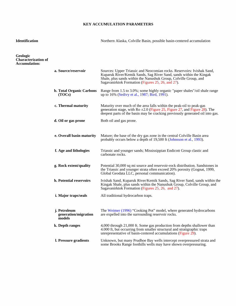
KEY ACCUMULATION PARAMETERS
Identification Northern Alaska, Colville Basin, possible basin-centered accumulation
Geologic Characterization of Accumulation:
a. Source/reservoir Sources: Upper Triassic and Neocomian rocks. Reservoirs: Ivishak Sand, Kuparuk River/Kemik Sands, Sag River Sand, sands within the Kingak Shale, plus sands within the Nanushuk Group, Colville Group, and Sagavanirktok Formation (Figures 25, 26, and 27).
b. Total Organic Carbons (TOCs)
Range from 1.5 to 3.0%; some highly organic "paper shales"/oil shale range up to 16% (Sedivy et al., 1987; Bird, 1991).
c. Thermal maturity Maturity over much of the area falls within the peak-oil to peak-gas generation stage, with Ro ±2.0 (Figure 25, Figure 27, and Figure 28). The deepest parts of the basin may be cracking previously generated oil into gas.
d. Oil or gas prone Both oil and gas prone.
e. Overall basin maturity Mature; the base of the dry gas zone in the central Colville Basin area probably occurs below a depth of 19,500 ft (Johnsson et al., 1993).
f. Age and lithologies Triassic and younger sands; Mississippian Endicott Group clastic and carbonate rocks.
g. Rock extent/quality Potential 30,000 sq mi source and reservoir-rock distribution. Sandstones in the Triassic and younger strata often exceed 20% porosity (Gognat, 1999, Global Geodata LLC, personal communication).
h. Potential reservoirs Ivishak Sand, Kuparuk River/Kemik Sands, Sag River Sand, sands within the Kingak Shale, plus sands within the Nanushuk Group, Colville Group, and Sagavanirktok Formation (Figures 25, 26, and 27).
i. Major traps/seals All traditional hydrocarbon traps.
j. Petroleum generation/migration models
The Weimer (1996) “Cooking Pot” model, where generated hydrocarbons are expelled into the surrounding reservoir rocks.
k. Depth ranges 4,000 through 21,000 ft. Some gas production from depths shallower than 4.000 ft, but occurring from smaller structural and stratigraphic traps unrepresentative of basin-centered accumulations (Figure 29).
l. Pressure gradients Unknown, but many Prudhoe Bay wells intercept overpressured strata and some Brooks Range foothills wells may have shown overpressuring.

Production and Drilling Characteristics:
a. Important fields/reservoirs
South Barrow, Fish Creek, Umiat, Meade, Simpson, Wolf Creek, Gubik, Square Lake, East Umiat, East Barrow, East Kurupa, Eagle Creek, Walakpa, and Sikulik (Figure 30).
b. Cumulative production See Figure 31. Outside the Prudhoe Bay producing complex, there is little production on the North Slope. South Barrow Gas field presently supplies only domestic gas to the town of Barrow.
Economic Characteristics:
a. Inert gas content Possible, but unknown.
b. Recovery Unknown
c. Pipeline infrastructure Poor to non-existent.
d. Exploration maturity relative to other basins
Immature
e. Sediment consolidation Moderate to good.
f. Porosity/completion problems
Unknown
g. Permeability Probably high, but variable.
h. Porosity Highly variable, but porosity in reservoirs exceeds 20% (Gognat, 1999, Global Geodata LLC, personal communication).
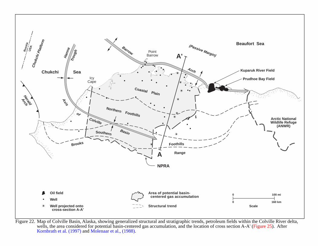
0 100 mi
0 160 kmScale
Oil field
Well
Well projected onto cross-section A-A'
Area of potential basin- centered gas accumulation
Structural trend
Figure 22. Map of Colville Basin, Alaska, showing generalized structural and stratigraphic trends, petroleum fields within the Colville River delta, wells, the area considered for potential basin-centered gas accumulation, and the location of cross section A-A' (Figure 25). After Kornbrath et al. (1997) and Molenaar et al., (1988).
Rus
sia
US
A
NPRA
Arctic NationalWildlife Refuge
(ANWR)
Brooks
Range
Southern
Foothills
Northern Foothills
Coastal Plain
Beaufort Sea
PointBarrow
IcyCape
Chukchi Sea
Barrow
Han
naTr
ough
Arch
Axis
ofColville
Basin
Chu
kchi
Pla
tform
Herald
Arch
(Passive Margin)
Kuparuk River Field
Prudhoe Bay Field
A
A'
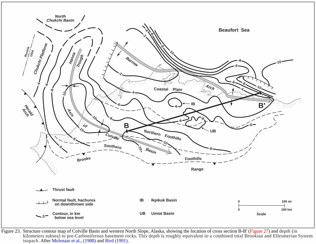
0 100 mi
0 160 kmScale
Thrust fault
Normal fault, hachures on downthrown side
Contour, in km below sea level-2
Figure 23. Structure contour map of Colville Basin and western North Slope, Alaska, showing the location of cross section B-B' (Figure 27) and depth (in kilometers subsea) to pre-Carboniferous basement rocks. This depth is roughly equivalent to a combined total Brookian and Ellesmerian Systemisopach. After Molenaar et al., (1988) and Bird (1991).
IB Ikpikuk Basin
UB Umiat Basin
Rus
sia
US
A
Brooks
Range
Southern
Foothills
Northern Foothills
Coastal Plain
Beaufort Sea
BarrowHan
naTr
ough
Arch
Axis
of
Colville
Basin
Chu
kchi
Pla
tform
Herald
Arch
NorthChukchi Basin
B
B'
-4
-4
-2
-2
-4
-4
-6
-6
-6
-8
-8
-8
-6
-6
-6
-6-6
-6
-8
-8
-8 -8
-8
-10
-10
-10
-10
-10
-10
-10
-10
IB
UB
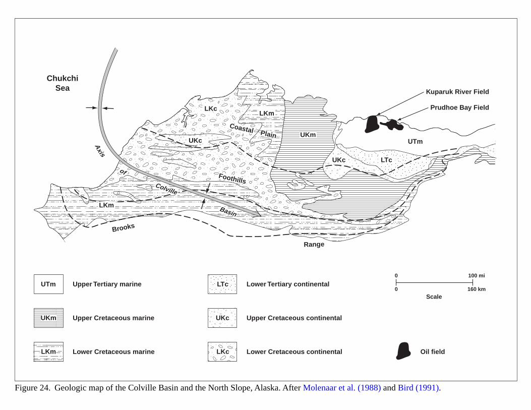
0 100 mi
0 160 kmScale
Upper Tertiary marine
Upper Cretaceous marine
Lower Cretaceous marine
Lower Tertiary continental
Upper Cretaceous continental
Oil fieldLower Cretaceous continental
Figure 24. Geologic map of the Colville Basin and the North Slope, Alaska. After Molenaar et al. (1988) and Bird (1991).
UTm
UKm UKc
LKc
LTc
LKm
ChukchiSea Kuparuk River Field
Prudhoe Bay Field
Brooks
Range
Foothills
Coastal Plain
Axis
of
Colville
Basin
UTm
UKc
UKc
LKc
UKm
LKm
LKm
LTc
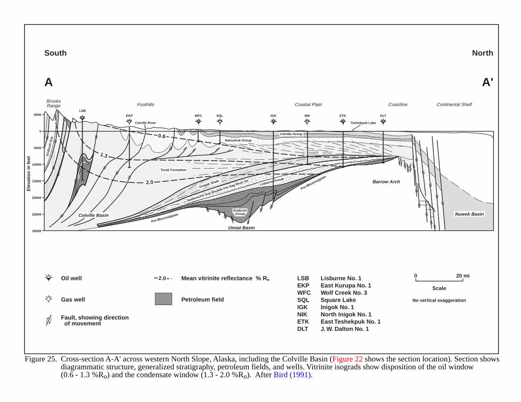
Figure 25. Cross-section A-A' across western North Slope, Alaska, including the Colville Basin (Figure 22 shows the section location). Section showsdiagrammatic structure, generalized stratigraphy, petroleum fields, and wells. Vitrinite isograds show disposition of the oil window (0.6 - 1.3 %Ro) and the condensate window (1.3 - 2.0 %Ro). After Bird (1991).
Mean vitrinite reflectance % Ro
Petroleum field
Oil well LSBEKPWFCSQLIGKNIKETKDLT
Lisburne No. 1East Kurupa No. 1Wolf Creek No. 3Square LakeInigok No. 1North Inigok No. 1East Teshekpuk No. 1J. W. Dalton No. 1
Gas well
Fault, showing direction of movement
2.0 0 20 mi
No vertical exaggeration
Scale
5000
0
5000
10000
15000
20000
25000
30000
Ele
vati
on
in f
eet
A
South North
A'BrooksRange Foothills
Colville River Teshekpuk Lake
Coastal Plain Coastline Continental ShelfLSB
EKP WFC SQL IGK NIK ETK DLT
0.6
2.0
1.3
Pre-Mississippian
Pre-Mississippian
Umiat Basin
Colville Basin Nuwok Basin
Barrow Arch
Torok Formation
Nanushuk Group
EndicottGroup
Lisburne Group
Colville Group
Kingak Shale
Sadlerochit Grp-Shublik Fm-Sag River Ss
End
icot
t Grp
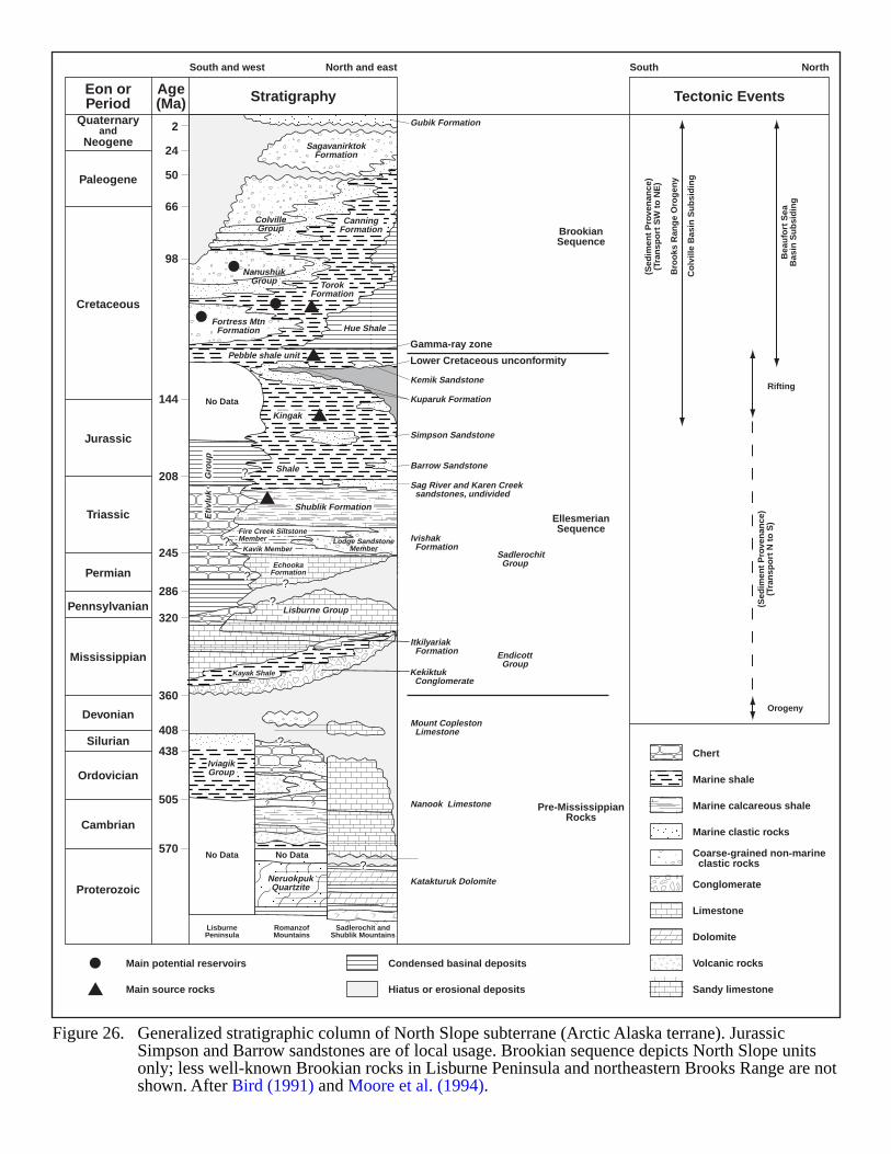
Figure 26. Generalized stratigraphic column of North Slope subterrane (Arctic Alaska terrane). Jurassic Simpson and Barrow sandstones are of local usage. Brookian sequence depicts North Slope units only; less well-known Brookian rocks in Lisburne Peninsula and northeastern Brooks Range are notshown. After Bird (1991) and Moore et al. (1994).
Condensed basinal deposits
Chert
Marine shale
Marine calcareous shale
Marine clastic rocks
Conglomerate
Coarse-grained non-marine clastic rocks
Limestone
Dolomite
Volcanic rocks
Sandy limestoneHiatus or erosional deposits
Main potential reservoirs
Main source rocks
Quaternaryand
Neogene
Paleogene
Stratigraphy Tectonic EventsAge(Ma)
Eon orPeriod
Cretaceous
Jurassic
Triassic
Permian
Pennsylvanian
Mississippian
Devonian
Silurian
Ordovician
Cambrian
Proterozoic
South and west North and east South North
Gubik Formation
SagavanirktokFormation
Kemik Sandstone
Simpson Sandstone
Barrow Sandstone
Sag River and Karen Creek sandstones, undivided
Kuparuk Formation
Ivishak Formation
Mount Copleston Limestone
Nanook Limestone
Katakturuk Dolomite
Itkilyariak Formation
Sadlerochit Group
Endicott Group
Gamma-ray zone
Lower Cretaceous unconformity
2
24
50
66
98
144
208
245
286
320
360
408
438
505
570No Data
LisburnePeninsula
RomanzofMountains
Sadlerochit andShublik Mountains
No Data
No Data
ColvilleGroup
TorokFormation
CanningFormation
NanushukGroup
Fortress MtnFormation
Pebble shale unit
Hue Shale
Eti
vlu
kG
rou
p
Kingak
Shale
Shublik Formation
Fire Creek SiltstoneMember
Kavik MemberLodge Sandstone
Member
EchookaFormation
Kayak Shale Kekiktuk Conglomerate
Lisburne Group
IviagikGroup
NeruokpukQuartzite
EllesmerianSequence
Pre-MississippianRocks
BrookianSequence
(Sed
imen
t P
rove
nan
ce)
(Tra
nsp
ort
SW
to
NE
)
(Sed
imen
t P
rove
nan
ce)
(Tra
nsp
ort
N t
o S
)
Bro
oks
Ran
ge
Oro
gen
y
Co
lvill
e B
asin
Su
bsi
din
g
Bea
ufo
rt S
eaB
asin
Su
bsi
din
g
Rifting
Orogeny
?
?
?
??
?
?
?
??
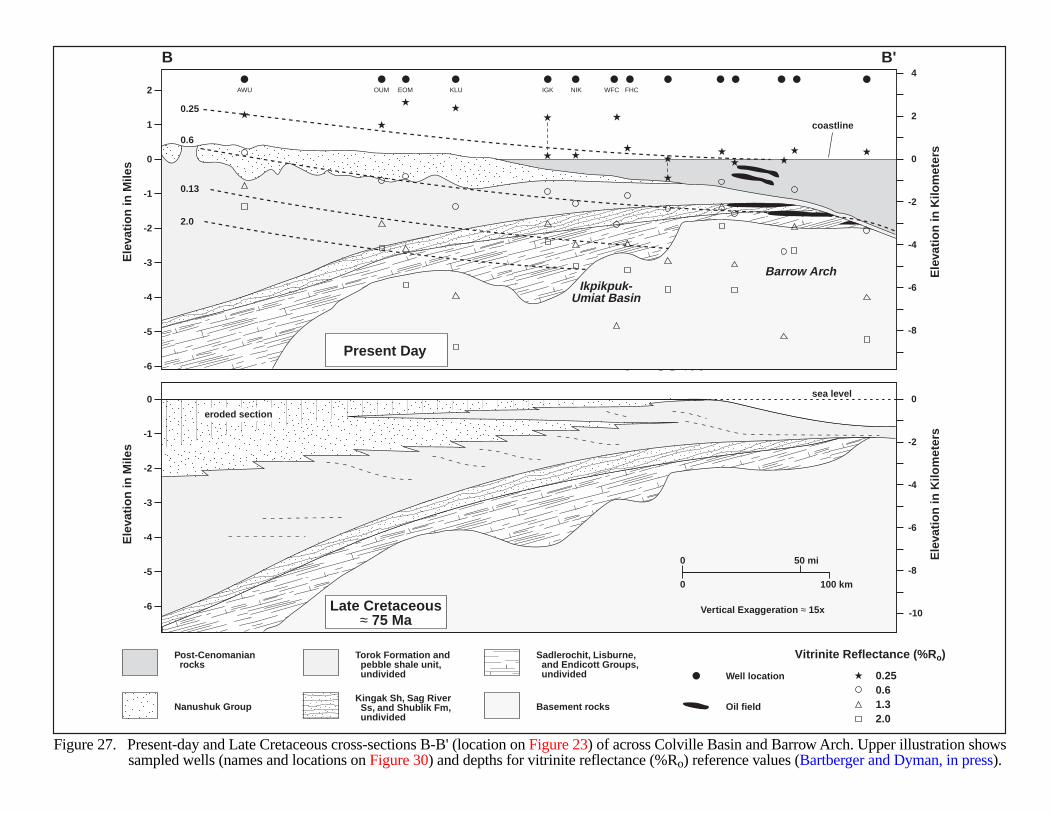
Figure 27. Present-day and Late Cretaceous cross-sections B-B' (location on Figure 23) of across Colville Basin and Barrow Arch. Upper illustration showssampled wells (names and locations on Figure 30) and depths for vitrinite reflectance (%Ro) reference values (Bartberger and Dyman, in press).
Nanushuk Group Basement rocks
Torok Formation and pebble shale unit, undivided
Post-Cenomanian rocks
Sadlerochit, Lisburne, and Endicott Groups, undivided
Vitrinite Reflectance (%Ro)
Kingak Sh, Sag River Ss, and Shublik Fm, undivided
0.250.61.32.0
Oil field
Well location
0
1
2
-1
-2
-3
-4
-5
-6
0
2
4
-2
-4
-6
-8
Ele
vati
on
in M
iles
Ele
vati
on
in K
ilom
eter
s
0
-1
-2
-3
-4
-5
-6
0
-2
-4
-6
-8
-10
Ele
vati
on
in M
iles
Ele
vati
on
in K
ilom
eter
s
0.25
0.6
0.13
2.0
Ikpikpuk-Umiat Basin
Barrow Arch
0 100 km
0 50 mi
Present Day
Late Cretaceous≈ 75 Ma
coastline
sea level
eroded section
Vertical Exaggeration ≈ 15x
B B'
AWU OUM EOM KLU IGK NIK WFC FHC
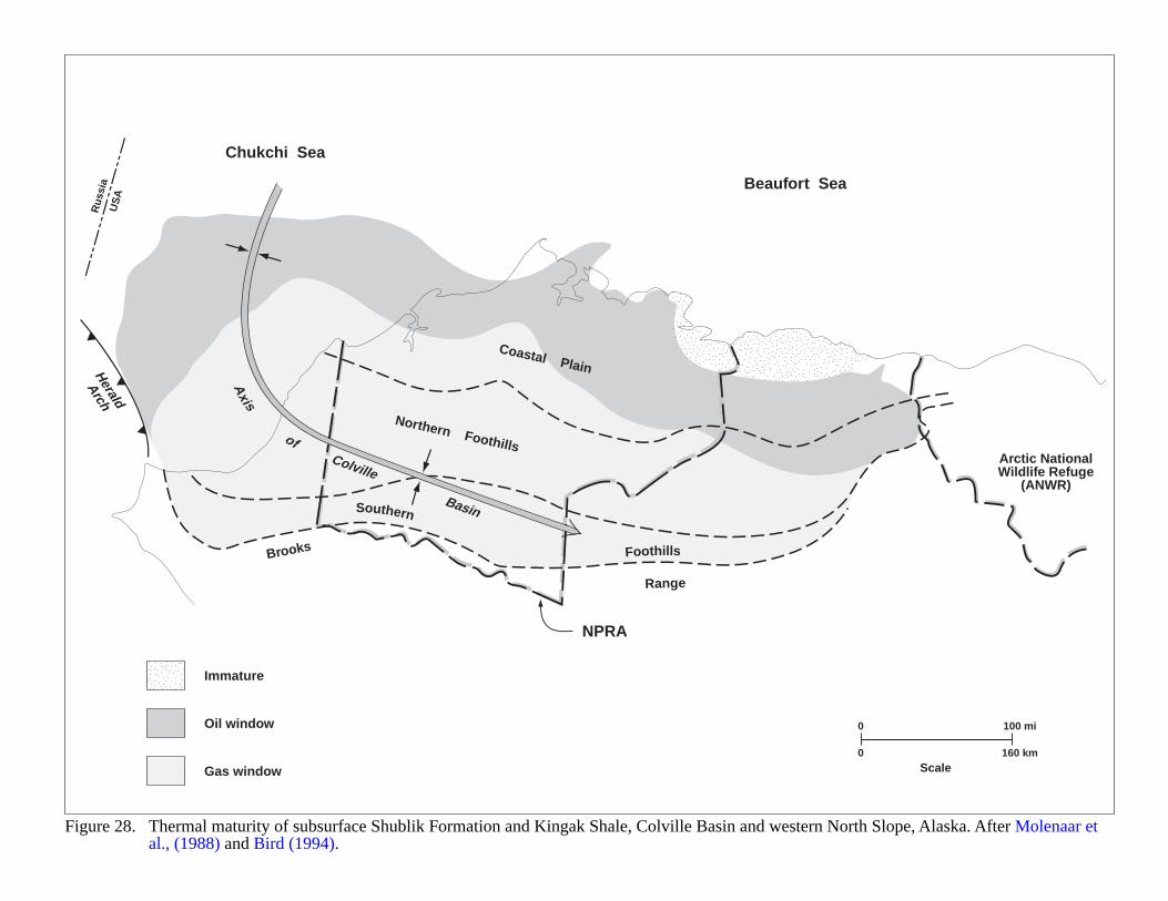
Figure 28. Thermal maturity of subsurface Shublik Formation and Kingak Shale, Colville Basin and western North Slope, Alaska. After Molenaar et al., (1988) and Bird (1994).
0 100 mi
0 160 kmScale
Immature
Oil window
Gas window
Beaufort Sea
Chukchi Sea
Rus
sia
US
A
NPRA
Arctic NationalWildlife Refuge
(ANWR)
Brooks
Range
Southern
Foothills
Northern Foothills
Coastal Plain
Axis
ofColville
Basin
Herald
Arch
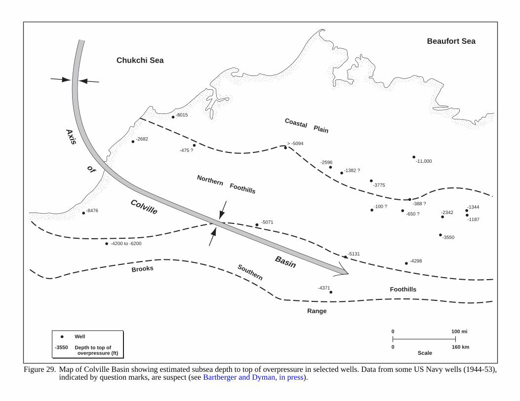
Figure 29. Map of Colville Basin showing estimated subsea depth to top of overpressure in selected wells. Data from some US Navy wells (1944-53),indicated by question marks, are suspect (see Bartberger and Dyman, in press).
-3550
Well
Depth to top of overpressure (ft)
0 100 mi
0 160 kmScale
Chukchi Sea
Beaufort Sea
Brooks
Range
Southern
Foothills
Northern Foothills
Coastal PlainAxis
of
Colville
Basin
-4200 to -6200
-8476
-2682
-475 ?
-8015
> -5094
-11,000
-1382 ?
-2596
-3775
-388 ?
-2342-100 ?
-5131
-4371
-5071
-4298
-3550
-650 ?
-1344
-1187
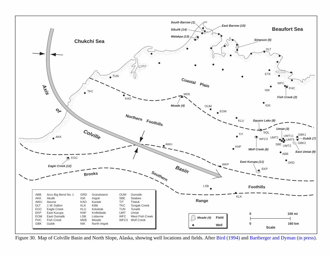
Figure 30. Map of Colville Basin and North Slope, Alaska, showing well locations and fields. After Bird (1994) and Bartberger and Dyman (in press).
0 100 mi
0 160 kmScale
Field
Well
Meade (4)
ABBAKKAWUDLTEGCEKPEOMFHCGBK
Arco Big Bend No. 1AkulikAwunaJ. W. DaltonEagle CreekEast KurupaEast OumalikFish CreekGubik
GRDIGKKAOKLKKLUKNFLSBMDENIK
GrandstandInigokKaolakKillikKoluktakKnifebladeLisburneMeadeNorth Inigok
OUMSBETITTKCTUNUMTWFCWFC3
OumalikSeabeeTitalukTungak CreekTunalikUmiatWest Fish CreekWolf Creek
Chukchi Sea
Beaufort Sea
Brooks
Range
Southern
Foothills
Northern Foothills
Coastal PlainAxis
of
Colville
Basin
EGC
AKK
TKC
KAO
TUN
MDE
DLT
ETK
FHC
WFC
NIK
IGK
EOM
OUM
KLU
SQL
SBE
TIT
KNF
WKP
LSB
KLK
AWU
EKP
GRD
ABB
WFC3 UMT1GBK1
GBK2
UMT11UMT5
UMT2
South Barrow (1)East Barrow (10)
Simpson (5)
Fish Creek (2)
Square Lake (8)
Wolf Creek (6)
Eagle Creek (12)East Kurupa (11)
Sikulik (14)
Walakpa (13)
Umiat (3)
East Umiat (9)
Gubik (7)
Meade (4)
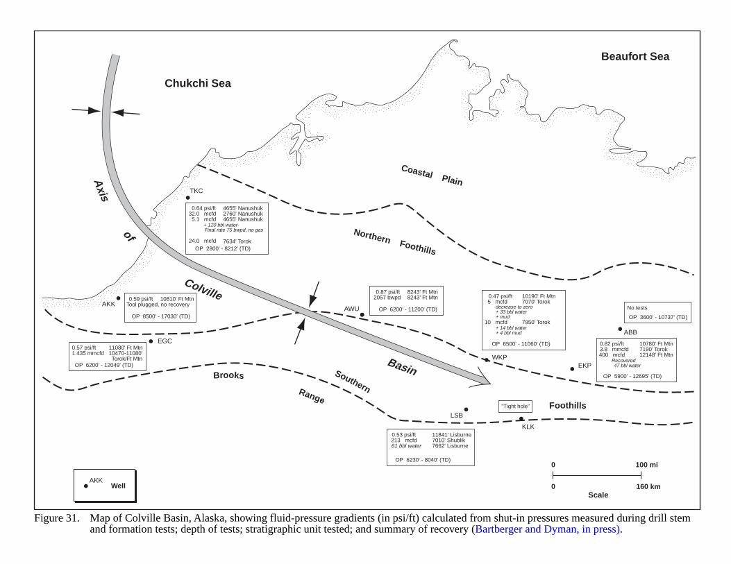
Well
Figure 31. Map of Colville Basin, Alaska, showing fluid-pressure gradients (in psi/ft) calculated from shut-in pressures measured during drill stemand formation tests; depth of tests; stratigraphic unit tested; and summary of recovery (Bartberger and Dyman, in press).
0 100 mi
0 160 kmScale
AKK
Chukchi Sea
Beaufort Sea
Brooks
Range
Southern
Foothills
Northern Foothills
Coastal PlainAxis
of
Colville
Basin
EGC
AKK
TKC
WKP
LSB
KLK
AWU
EKP
ABB
0.64 psi/ft32.0 mcfd5.1 mcfd
+ 120 bbl water- Final rate 75 bwpd, no gas
24.0 mcfd
4655' Nanushuk2760' Nanushuk4655' Nanushuk
7634' TorokOP 2800' - 8212' (TD)
0.87 psi/ft 2057 bwpd
8243' Ft Mtn8243' Ft Mtn
OP 6200' - 11200' (TD)
0.57 psi/ft 1.435 mmcfd
11080' Ft Mtn10470-11080' Torok/Ft Mtn
OP 6200' - 12049' (TD)
0.59 psi/ft Tool plugged, no recovery
10810' Ft Mtn
OP 8500' - 17030' (TD)
No tests
OP 3600' - 10737' (TD)
"Tight hole"
0.47 psi/ft 5 mcfd decrease to zero + 33 bbl water + mud 10 mcfd + 14 bbl water + 4 bbl mud
10190' Ft Mtn7070' Torok
7950' Torok
OP 6500' - 11060' (TD) 0.82 psi/ft 3.8 mmcfd 400 mcfd Recovered 47 bbl water
10780' Ft Mtn7190' Torok12148' Ft Mtn
OP 5900' - 12695' (TD)
0.53 psi/ft 213 mcfd 61 bbl water
11841' Lisburne7010' Shublik7662' Lisburne
OP 6230' - 8040' (TD)
77
COOK INLET, ALASKA
GEOLOGIC SETTING
The Cook Inlet basin is a narrow elongate trough of Mesozoic and Tertiary sediments, covering approximately11,000 square miles in south-central Alaska (Figure 32). The basin trends NNE-SSW and is bounded on thenorthwest by granitic batholiths of the Alaska-Aleutian range and the Talkeetna mountains, and on the southeast bythe Chugach terrane that makes up the Kenai Mountains (Magoon, 1994). The Border Ranges, Castle Mountain, andBruin Bay faults are major structural features (Figure 32) (Boss et al., 1975). The Outer Continent Shelf area liesbetween these faults and contains anticlinal structures and faults that may be potential traps for hydrocarbons(Magoon, 1976).
Dickinson (1971) described the basin as a trench-arc gap type: a Cenozoic residual forearc basin in a convergentcontinental margin along the northwest Pacific Rim. Cook Inlet basin development began as a backarc basin duringthe Jurassic, evolving to a forearc basin in the Cenozoic (Magoon, 1994). Numerous high angle reverse faultsindicate compression throughout the Mesozoic and Cenozoic.
Kelly and Halbouty (1966) estimated the maximum sediment thickness in the deepest part of the basin to be40,000 ft. Cook Inlet sediments range in age from Upper Triassic to Recent, but consist mostly of Upper Jurassicand Tertiary rocks (Figure 33). The Middle and Upper Jurassic units are thick, but a significant mid-Cretaceousunconformity has removed the Lower Cretaceous section. Boss et al. (1975) considered the Lower Jurassic volcanicrocks to be the economic "basement.”
During the Tertiary uplift and erosion occurred continuously until termination by a widespread Late Pliocene-Pleistocene orogeny. The Tertiary section is part of the Kenai Group, which is separated from the West ForelandFormation (Eocene) by a thin but widespread unconformity marked by a basal conglomerate. The Kenai Groupconsists of three formations: Tyonek, Beluga, and Sterling. The Tyonek Formation includes the Hemlock SandstoneMember.
HYDROCARBON PRODUCTION
The most significant hydrocarbon production in the Cook Inlet basin occurs in Tertiary rocks which reach amaximum thickness of 25,000 ft in the deepest part of the basin (Smith, 1995). These rocks consist of a thicksequence of alluvial deposits. Of the total oil produced to 1994, Magoon (1994) noted that 80% originated from theHemlock Conglomerate, 20% from the Lower Tyonek, and minor amounts from the West Foreland Formation.Discovered resources exceed 1.2 BBO. Unassociated natural gas occurs in shallower younger reservoirs and accountsfor most of the Cook Inlet gas production (Magoon and Kirchner, 1990). This gas is found in the Beluga andSterling formations, may be biogenic, and primarily originates from Tertiary coals (Molenaar, 1996). Only minoramounts of oil have been produced from Mesozoic rocks. The Middle Chuitna Formation in the upper Cook Inletand the Upper Triassic-Middle Jurassic rocks in the lower Cook Inlet are the source rocks for oil. Siltstones andclaystones associated with coals compose the seals.
Bird (1996) identified three petroleum systems in the Cook Inlet
1. Hemlock-Tyonek oil.
2. Beluga-Sterling gas.
3. Late Mesozoic oil. This system includes Lower Jurassic to Upper Cretaceous rocks. This interval appears tobe the only stratigraphic section capable of supporting a basin-centered gas play in the Cook Inlet basin.
78
To date, production in the Late Mesozoic has been marginal because of poor-quality reservoir rocks. Limitedproduction has occurred from marine and turbidite sandstones within the Upper Cretaceous Matanuska and KaguyakFormations, Lower Cretaceous sandstones, and the Upper Jurassic Naknek Formation. Lateral permeability barrierswithin siltstones seal these reservoirs and the reservoirs in the unconformably overlying Lower Tertiary WestForeland Formation. However, most of these fields are faulted anticlinal structures truncated by overlying Tertiaryrocks. Oil was generated during Eocene and Pliocene periods (Magoon et al., 1996a).
The Tertiary section (Beluga-Sterling gas and Tyonek/Paleocene Chickaloon coals) in the upper Cook Inletincludes coals as source rocks within an area described by Molenaar (1996) as thermally immature. This area containsgas fields having localized sources. In contrast, Smith (1995) reported carbon isotope analyses of gas from coals inthe Tyonek Formation that indicated both biogenic and thermogenic origins. The reported gas volumes from coalsranged from 63 standard cubic feet per ton (scf/ton) at 521 ft in depth to 245 scf/ton at 1,236 ft in depth.
EVIDENCE FOR BASIN-CENTERED GAS
Although few holes were drilled in the central trough of the Cook Inlet, limited data (mostly from the COSTNo. 1 well shown in Figure 32) indicates a significant increase in thermal maturity to Ro = 0.87 in the lower part ofthe Upper Jurassic Naknek Formation. Thermal maturity of Middle Jurassic source rocks ranges from immature tomature on the flanks of the basin and postmature in the deepest part of the basin (Magoon, 1994). However,conflicting interpretations place the top of the oil window (Ro = 0.6) at disparate depths: Magoon (1994) projects thedepth at 21,000 ft in the vicinity of the Swanson River oil field (Figure 34), whereas Johnsson et al. (1993) placethe oil window top at 5,000 m depth (about 16,400 ft) (Figure 35). This difference dramatically changes the basinarea that may be thermally mature.
Frequent hydrocarbon shows occur within the Middle Jurassic interval. Significant variations in pressuregradients occur within the current oil and gas producing fields and flank the area of the potential basin-centeredaccumulation. Although this does not directly indicate pressure seals occur in the central trough of the Cook Inlet,the data suggests that lateral permeability barriers do exist within the conventionally trapped hydrocarbonaccumulations. Source rocks within the Middle Jurassic Tuxedni Group indicate adequate but somewhat limitedsource potential (TOC content of 0.8 to 2.1 weight %). A normal geothermal gradient of 12.5 °F per 1000 ft (in theCOST No. 1 well) also appears to lessen the possibility of a basin-centered accumulation at shallow depths.
Depending on the oil generation window interpretation, basin-centered gas accumulations in the Cook Inlet maypotentially range in depth from less than 3,280-19,685 ft for the upper limit, to 41,891 ft for the floor.
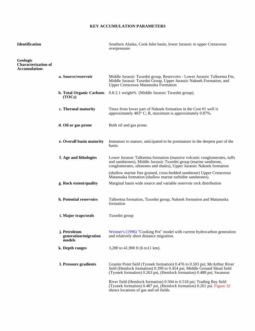
KEY ACCUMULATION PARAMETERS
Identification Southern Alaska, Cook Inlet basin, lower Jurassic to upper Cretaceous overpressure
Geologic Characterization of Accumulation:
a. Source/reservoir Middle Jurassic Tuxedni group, Reservoirs - Lower Jurassic Talkeetna Fm, Middle Jurassic Tuxedni Group, Upper Jurassic Naknek Formation, and Upper Cretaceous Matanuska Formation
b. Total Organic Carbons (TOCs)
0.8-2.1 weight% (Middle Jurassic Tuxedni group).
c. Thermal maturity Tmax from lower part of Naknek formation in the Cost #1 well is approximately 483° C; Ro maximum is approximately 0.87%.
d. Oil or gas prone Both oil and gas prone.
e. Overall basin maturity Immature to mature, anticipated to be postmature in the deepest part of the basin.
f. Age and lithologies Lower Jurassic Talkeetna formation (massive volcanic conglomerates, tuffs and sandstones), Middle Jurassic Tuxedni group (marine sandstone, conglomerates, siltstones and shales), Upper Jurassic Naknek formation
(shallow marine fine grained, cross-bedded sandstone) Upper Cretaceous Matanuska formation (shallow marine turbidite sandstones).
g. Rock extent/quality Marginal basin wide source and variable reservoir rock distribution
h. Potential reservoirs Talkeetna formation, Tuxedni group, Naknek formation and Matanuska formation
i. Major traps/seals Tuxedni group
j. Petroleum generation/migration models
Weimer's (1996) "Cooking Pot" model with current hydrocarbon generation and relatively short distance migration.
k. Depth ranges 3,280 to 41,900 ft (6 to11 km).
l. Pressure gradients Granite Point field (Tyonek formation) 0.476 to 0.503 psi; McArthur River field (Hemlock formation) 0.399 to 0.454 psi; Middle Ground Shoal field (Tyonek formation) 0.263 psi, (Hemlock formation) 0.488 psi; Swanson
River field (Hemlock formation) 0.504 to 0.518 psi; Trading Bay field (Tyonek formation) 0.487 psi, (Hemlock formation) 0.261 psi. Figure 32 shows locations of gas and oil fields.

Production and Drilling Characteristics:
a. Important fields/reservoirs
Only marginal production occurs within the Upper Jurassic Naknek to Upper Cretaceous Matanuska formations.
b. Cumulative production
Economic Characteristics:
a. Inert gas content
b. Recovery
c. Pipeline infrastructure Good
d. Exploration maturity relative to other basins
e. Sediment consolidation Good to moderate consolidation.
f. Porosity/completion problems
Low porosity because of probable clays and migrating fines.
g. Permeability Not available, but expected to be highly variable.
h. Porosity Highly variable
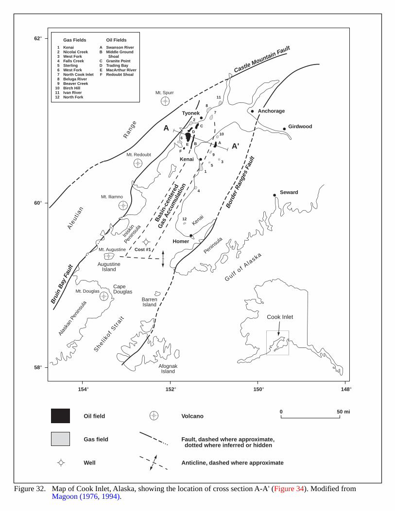
154° 152° 150° 148°
58°
60°
62°
Inisk
inPe
nins
ula
Kenai
Peninsula
AfognakIsland
BarrenIsland
Cost #1
AugustineIsland
Alas
kan
Peni
nsul
a
Ale
utia
n
R
ange
CapeDouglas
Gulf of A
laska
She
l ikof
Str
ait
Girdwood
Seward
Homer
Cook Inlet
Mt. Douglas
Mt. Iliamno
Mt. Augustine
Mt. Redoubt
Mt. Spurr
Castle Mountain Fault
Bor
der R
ange
s Fa
ult
Bru
in B
ay F
ault
A
A'B
asin
-cen
tere
d
Gas
Acc
umul
atio
n
AnchorageTyonek
Kenai
1
7
C
D
E B
F
8
11
53
A
10
9
4
12
6
2
123456789
101112
KenaiNicolai CreekWest ForkFalls CreekSterlingWest ForkNorth Cook InletBeluga RiverBeaver CreekBirch HillIvan RiverNorth Fork
Gas Fields
AB
CDEF
Swanson RiverMiddle Ground ShoalGranite PointTrading BayMacArthur RiverRedoubt Shoal
Oil Fields
Figure 32. Map of Cook Inlet, Alaska, showing the location of cross section A-A' (Figure 34). Modified from Magoon (1976, 1994).
0 50 miOil field Volcano
Well
Fault, dashed where approximate, dotted where inferred or hidden
Anticline, dashed where approximate
Gas field
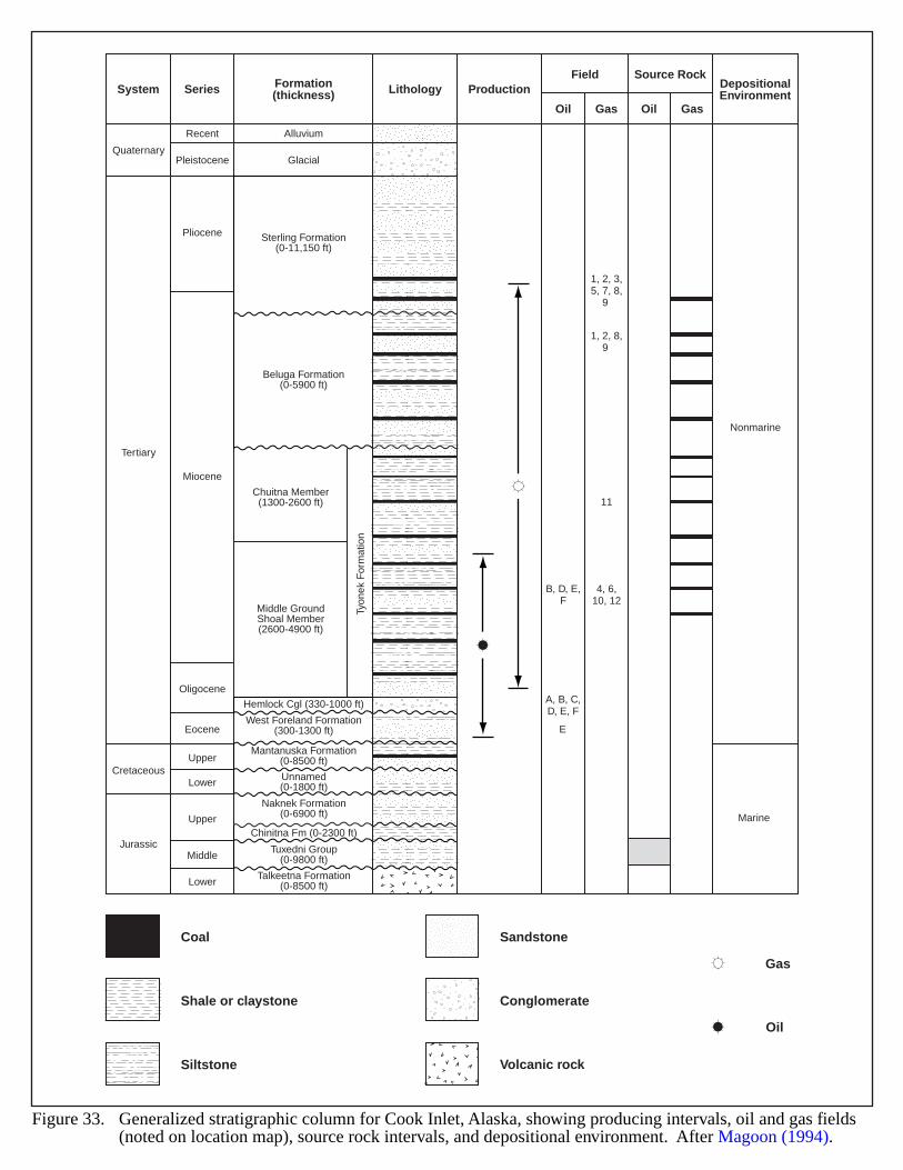
LithologyField
Oil Gas Oil Gas
Source RockDepositionalEnvironmentSeriesSystem
Quaternary
Tertiary
Nonmarine
Marine
Cretaceous
Jurassic
Recent
Pleistocene
Pliocene
Miocene
Oligocene
Eocene
Upper
Upper
Middle
Lower
Lower
Glacial
Formation(thickness) Production
Alluvium
Chuitna Member(1300-2600 ft)
Middle GroundShoal Member(2600-4900 ft)
Unnamed(0-1800 ft)
Tuxedni Group(0-9800 ft)
Tyon
ek F
orm
atio
n
Sterling Formation(0-11,150 ft)
Beluga Formation(0-5900 ft)
Hemlock Cgl (330-1000 ft)
West Foreland Formation(300-1300 ft)
Mantanuska Formation(0-8500 ft)
Naknek Formation(0-6900 ft)
Chinitna Fm (0-2300 ft)
Talkeetna Formation(0-8500 ft)
1, 2, 3,5, 7, 8,
9
1, 2, 8,9
11
4, 6,10, 12
B, D, E,F
A, B, C,D, E, F
E
Coal
Shale or claystone
Siltstone
Sandstone
Conglomerate
Volcanic rock
Gas
Oil
Figure 33. Generalized stratigraphic column for Cook Inlet, Alaska, showing producing intervals, oil and gas fields(noted on location map), source rock intervals, and depositional environment. After Magoon (1994).
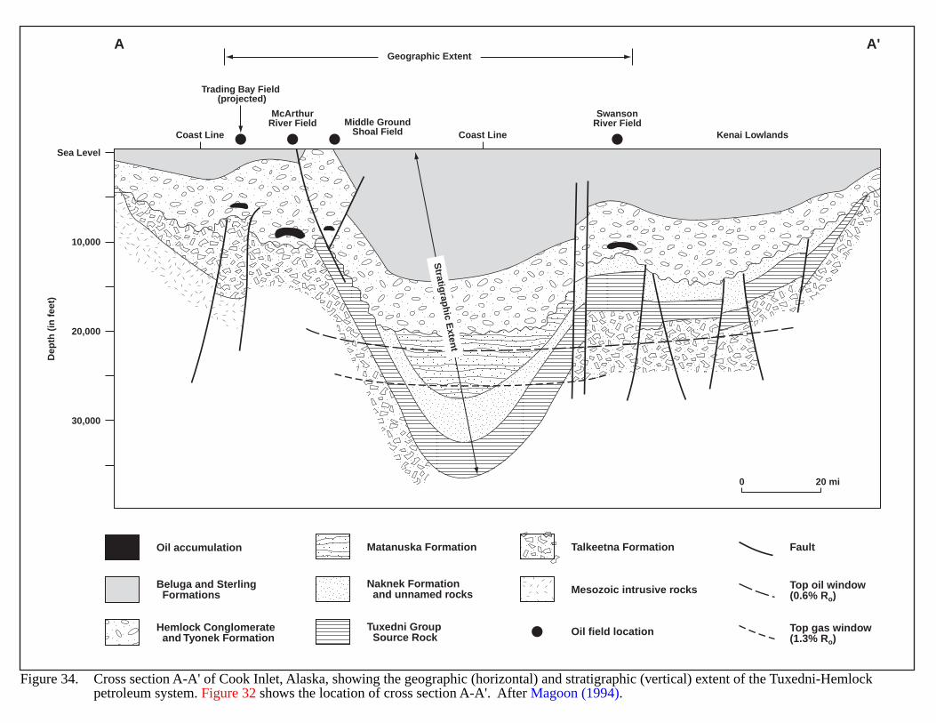
Trading Bay Field (projected)
McArthurRiver Field
SwansonRiver FieldMiddle Ground
Shoal Field
Geographic Extent
Stratig
raph
ic Exten
t
Sea Level
10,000
20,000
30,000
Dep
th (
in f
eet)
Coast Line Coast Line Kenai Lowlands
A A'
0 20 mi
Oil accumulation
Beluga and Sterling Formations
Hemlock Conglomerate and Tyonek Formation
Matanuska Formation
Naknek Formation and unnamed rocks
Tuxedni Group Source Rock
Talkeetna Formation
Oil field location
Mesozoic intrusive rocks
Fault
Top oil window(0.6% Ro)
Top gas window(1.3% Ro)
Figure 34. Cross section A-A' of Cook Inlet, Alaska, showing the geographic (horizontal) and stratigraphic (vertical) extent of the Tuxedni-Hemlockpetroleum system. Figure 32 shows the location of cross section A-A'. After Magoon (1994).
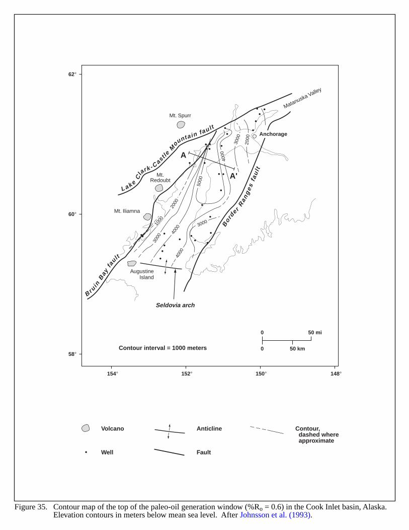
Mt. Spurr
Mt. Iliamna
AugustineIsland
Mt.Redoubt
62°
60°
58°
154° 152° 150° 148°
Matanuska Valley
Lake
Cla
rk - CastleM
ountain fau lt
Bor
der
Ran
ges
fau
lt
B ruin
Bay
fault
Seldovia arch
A
A'
1000
2000
5000
3000
2000
3000
4000
4000
4000
3000
Figure 35. Contour map of the top of the paleo-oil generation window (%Ro = 0.6) in the Cook Inlet basin, Alaska. Elevation contours in meters below mean sea level. After Johnsson et al. (1993).
Anchorage
Volcano
Well
Anticline Contour, dashed where approximate
Contour interval = 1000 meters
Fault
0 50 mi
0 50 km
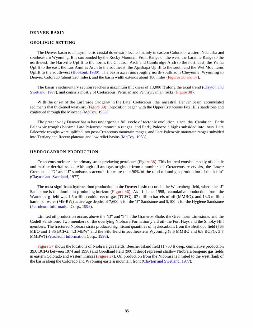
85
DENVER BASIN
GEOLOGIC SETTING
The Denver basin is an asymmetric crustal downwarp located mainly in eastern Colorado, western Nebraska andsoutheastern Wyoming. It is surrounded by the Rocky Mountain Front Range on the west, the Laramie Range to thenorthwest, the Hartville Uplift to the north, the Chadron Arch and Cambridge Arch to the northeast, the YumaUplift to the east, the Los Animas Arch to the southeast, the Apishapa Uplift to the south and the Wet MountainsUplift to the southwest (Bookout, 1980). The basin axis runs roughly north-southfrom Cheyenne, Wyoming toDenver, Colorado (about 320 miles), and the basin width extends about 180 miles (Figures 36 and 37).
The basin’s sedimentary section reaches a maximum thickness of 13,000 ft along the axial trend (Clayton andSwetland, 1977), and consists mostly of Cretaceous, Permian and Pennsylvanian rocks (Figure 38).
With the onset of the Laramide Orogeny in the Late Cretaceous, the ancestral Denver basin accumulatedsediments that thickened westward (Figure 39). Deposition began with the Upper Cretaceous Fox Hills sandstone andcontinued through the Miocene (McCoy, 1953).
The present-day Denver basin has undergone a full cycle of tectonic evolution since the Cambrian: EarlyPaleozoic troughs became Late Paleozoic mountain ranges, and Early Paleozoic highs subsided into lows. LatePaleozoic troughs were uplifted into post-Cretaceous mountain ranges, and Late Paleozoic mountain ranges subsidedinto Tertiary and Recent plateaus and low relief basins (McCoy, 1953).
HYDROCARBON PRODUCTION
Cretaceous rocks are the primary strata producing petroleum (Figure 38). This interval consists mostly of deltaicand marine detrital rocks. Although oil and gas originate from a number of Cretaceous reservoirs, the LowerCretaceous "D" and "J" sandstones account for more then 90% of the total oil and gas production of the basin"(Clayton and Swetland, 1977).
The most significant hydrocarbon production in the Denver basin occurs in the Wattenberg field, where the "J"Sandstone is the dominant producing horizon (Figure 36). As of June 1998, cumulative production from theWattenberg field was 1.5 trillion cubic feet of gas (TCFG), 67 million barrels of oil (MMBO), and 13.3 millionbarrels of water (MMBW) at average depths of 7,600 ft for the "J" Sandstone and 5,100 ft for the Hygiene Sandstone(Petroleum Information Corp., 1998).
Limited oil production occurs above the "D" and "J" in the Graneros Shale, the Greenhorn Limestone, and theCodell Sandstone. Two members of the overlying Niobrara Formation yield oil–the Fort Hays and the Smoky Hillmembers. The fractured Niobrara strata produced significant quantities of hydrocarbons from the Berthoud field (765MBO and 1.85 BCFG; 4.3 MBW) and the Silo field in southeastern Wyoming (8.5 MMBO and 6.8 BCFG; 3.7MMBW) (Petroleum Information Corp., 1998).
Figure 37 shows the locations of Niobrara gas fields. Beecher Island field (1,700 ft deep, cumulative production39.6 BCFG between 1974 and 1998) and Goodland field (900 ft deep) represent shallow Niobrara biogenic gas fieldsin eastern Colorado and western Kansas (Figure 37). Oil production from the Niobrara is limited to the west flank ofthe basin along the Colorado and Wyoming eastern mountain front (Clayton and Swetland, 1977).

86
EVIDENCE FOR BASIN-CENTERED GAS
Field data supports the existence of a basin-centered hydrocarbon accumulation in the Denver basin. Widespreadhydrocarbon shows occur within the interval below the Hygiene sandstone (Figure 40). In the area of the Wattenbergfield, Weimer (1996) reported overpressuring from the top of the Hygiene sandstone to the top of the Muddysandstone (Figure 40). These depths conform to a vitrinite reflectance anomaly that Smagala et al. (1984) plotted atand below the Terry-Hygiene boundary (Figure 41). Geothermal gradients as high as 30°F per 1,000 ft of burial–nearly double the norm for this basin–also occur in the vicinity of the Wattenberg field (Bookout, 1980). Well dataindicate that the overpressure in the Denver basin has an upper window depth of approximately 4,500 ft. Thisoverpressured zone eventually pinches out east of the Wattenberg field.
Figure 37 shows biogenic gas fields exists east of the limit of thermally-mature Niobrara source rocks.Significant underpressuring occurs in this area with reported pressure gradients as low as 0.21 psi/ft at the BeecherIsland field. Lockridge and Scholle (1978) note that Niobrara gas accumulations here are associated with low-reliefanticlinal closures; thus this area has a low potential for continuous-type accumulations.
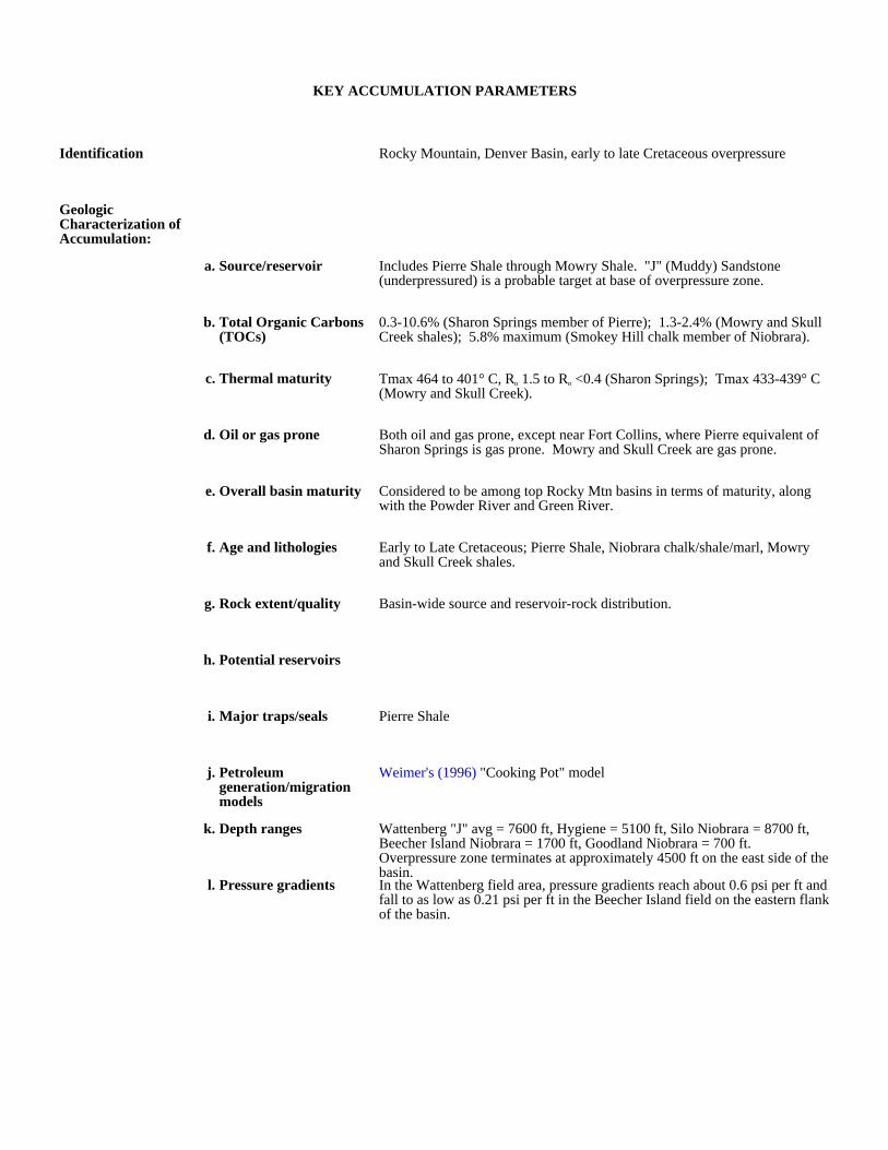
KEY ACCUMULATION PARAMETERS
Identification Rocky Mountain, Denver Basin, early to late Cretaceous overpressure
Geologic Characterization of Accumulation:
a. Source/reservoir Includes Pierre Shale through Mowry Shale. "J" (Muddy) Sandstone (underpressured) is a probable target at base of overpressure zone.
b. Total Organic Carbons (TOCs)
0.3-10.6% (Sharon Springs member of Pierre); 1.3-2.4% (Mowry and Skull Creek shales); 5.8% maximum (Smokey Hill chalk member of Niobrara).
c. Thermal maturity Tmax 464 to 401° C, Ro 1.5 to Ro <0.4 (Sharon Springs); Tmax 433-439° C (Mowry and Skull Creek).
d. Oil or gas prone Both oil and gas prone, except near Fort Collins, where Pierre equivalent of Sharon Springs is gas prone. Mowry and Skull Creek are gas prone.
e. Overall basin maturity Considered to be among top Rocky Mtn basins in terms of maturity, along with the Powder River and Green River.
f. Age and lithologies Early to Late Cretaceous; Pierre Shale, Niobrara chalk/shale/marl, Mowry and Skull Creek shales.
g. Rock extent/quality Basin-wide source and reservoir-rock distribution.
h. Potential reservoirs
i. Major traps/seals Pierre Shale
j. Petroleum generation/migration models
Weimer's (1996) "Cooking Pot" model
k. Depth ranges Wattenberg "J" avg = 7600 ft, Hygiene = 5100 ft, Silo Niobrara = 8700 ft, Beecher Island Niobrara = 1700 ft, Goodland Niobrara = 700 ft. Overpressure zone terminates at approximately 4500 ft on the east side of the basin.
l. Pressure gradients In the Wattenberg field area, pressure gradients reach about 0.6 psi per ft and fall to as low as 0.21 psi per ft in the Beecher Island field on the eastern flank of the basin.
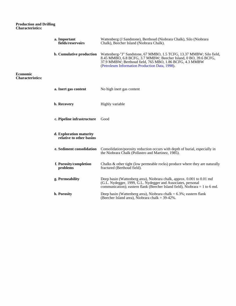
Production and Drilling Characteristics:
a. Important fields/reservoirs
Wattenberg (J Sandstone), Berthoud (Niobrara Chalk), Silo (Niobrara Chalk), Beecher Island (Niobrara Chalk).
b. Cumulative production Wattenberg-"J" Sandstone, 67 MMBO, 1.5 TCFG, 13.37 MMBW; Silo field, 8.45 MMBO, 6.8 BCFG, 3.7 MMBW; Beecher Island, 0 BO, 39.6 BCFG, 37.9 MMBW; Berthoud field, 765 MBO, 1.86 BCFG, 4.3 MMBW (Petroleum Information Production Data, 1998).
Economic Characteristics:
a. Inert gas content No high inert gas content
b. Recovery Highly variable
c. Pipeline infrastructure Good
d. Exploration maturity relative to other basins
e. Sediment consolidation Consolidation/porosity reduction occurs with depth of burial, especially in the Niobrara Chalk (Pollastro and Martinez, 1985).
f. Porosity/completion problems
Chalks & other tight (low permeable rocks) produce where they are naturally fractured (Berthoud field).
g. Permeability Deep basin (Wattenberg area), Niobrara chalk, approx. 0.001 to 0.01 md (G.L. Nydegger, 1999, G.L. Nydegger and Associates, personal communication); eastern flank (Beecher Island field), Niobrara = 1 to 6 md.
h. Porosity Deep basin (Wattenberg area), Niobrara chalk = 6.3%; eastern flank (Beecher Island area), Niobrara chalk = 39-42%.
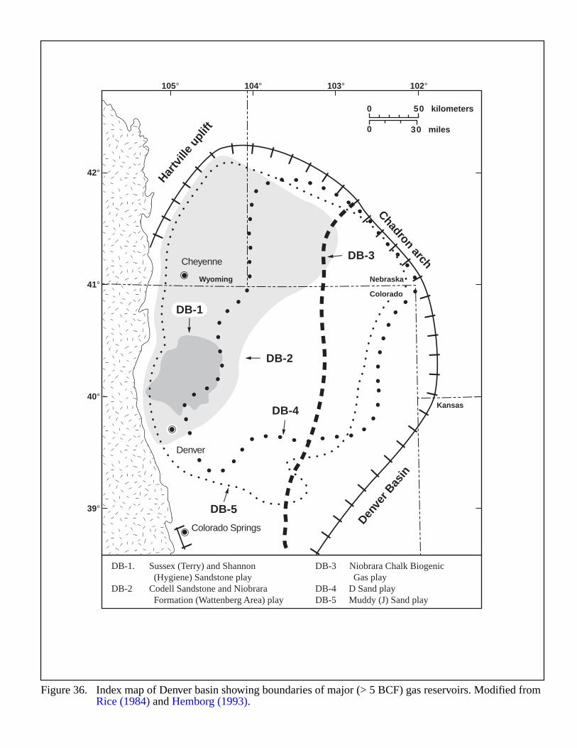
||
Denve
r Bas
in
Hartv
ille
uplif
t
||
||
||
||
||
||
||
||
||
||
||
||
||
||||
||
||
|
Chadron arch
DB-2
DB-1
DB-3
DB-5
DB-4
DB-1. Sussex (Terry) and Shannon DB-3 Niobrara Chalk Biogenic (Hygiene) Sandstone play Gas play
DB-2 Codell Sandstone and Niobrara DB-4 D Sand play Formation (Wattenberg Area) play DB-5 Muddy (J) Sand play
Figure 36. Index map of Denver basin showing boundaries of major (> 5 BCF) gas reservoirs. Modified from Rice (1984) and Hemborg (1993).
Wyoming Nebraska
Kansas
Colorado
Colorado Springs
Denver
Cheyenne
42°
41°
40°
39°
105° 104° 103° 102°
0 50 kilometers
30 miles0
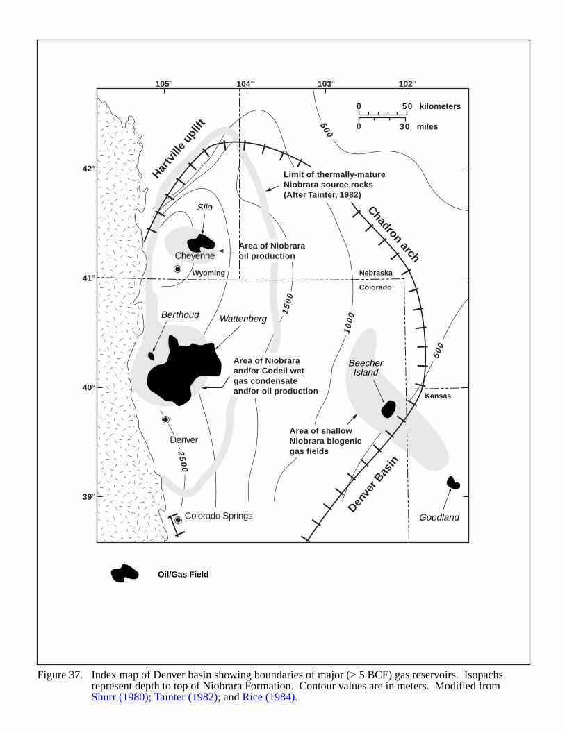
500
500
10
001
50
0
20
00
25
00
Silo
BeecherIsland
Berthoud Wattenberg
Goodland||
Denve
r Bas
in
Hartv
ille
uplif
t
||
||
||
||
||
||
||
||
||
||
||
||
||
||||
||
||
|
Chadron arch
Area of shallowNiobrara biogenicgas fields
Area of Niobraraand/or Codell wetgas condensateand/or oil production
Area of Niobraraoil production
Limit of thermally-matureNiobrara source rocks(After Tainter, 1982)
Figure 37. Index map of Denver basin showing boundaries of major (> 5 BCF) gas reservoirs. Isopachs represent depth to top of Niobrara Formation. Contour values are in meters. Modified from Shurr (1980); Tainter (1982); and Rice (1984).
Wyoming Nebraska
Kansas
Colorado
Colorado Springs
Denver
Cheyenne
42°
41°
40°
39°
105° 104° 103° 102°
0 50 kilometers
30 miles0
Oil/Gas Field
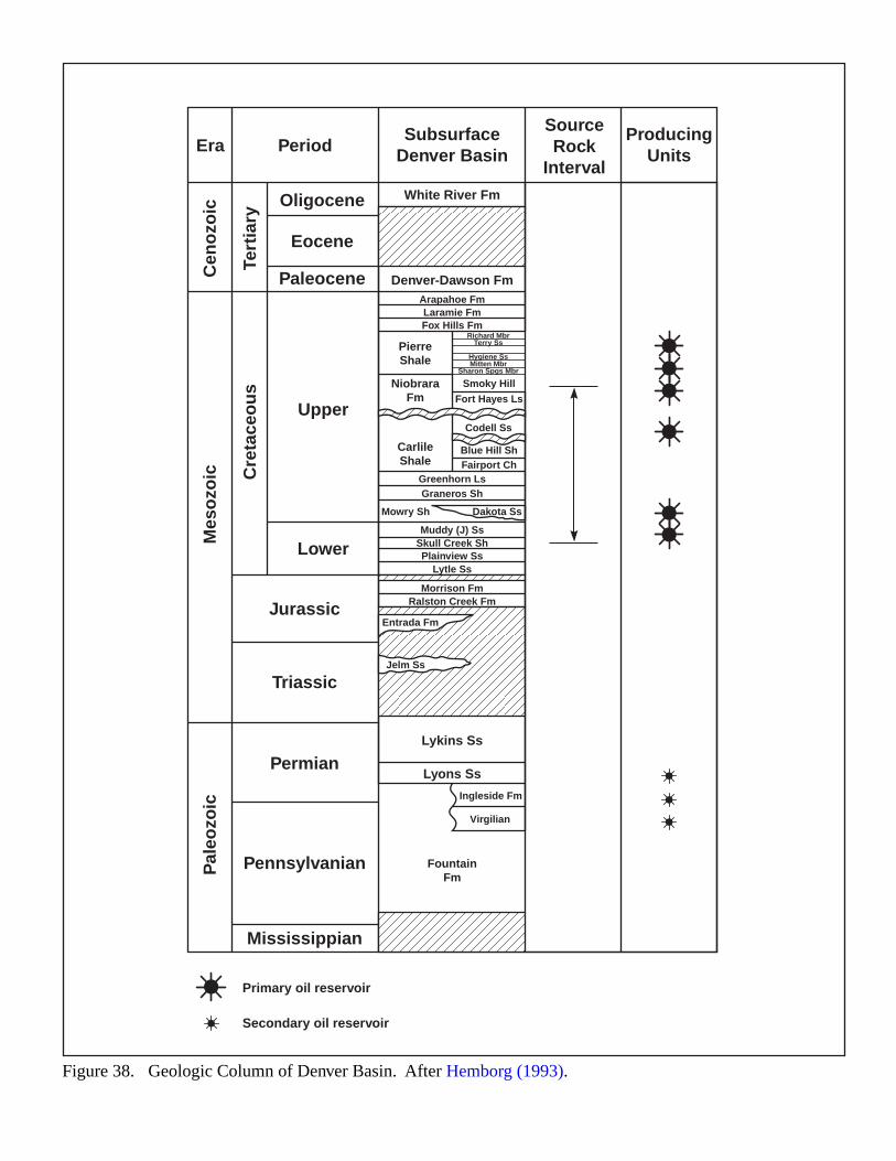
Era
Cen
ozo
ic
Tert
iary
Cre
tace
ou
s
Mes
ozo
icP
aleo
zoic
SubsurfaceDenver Basin
SourceRock
Interval
ProducingUnitsPeriod
Oligocene
Eocene
Paleocene
Jurassic
Lower
Upper
Triassic
Permian
Pennsylvanian
Mississippian
White River Fm
Denver-Dawson Fm
Lykins Ss
Lyons Ss
Arapahoe Fm
Richard MbrTerry Ss
Hygiene SsMitten Mbr
Sharon Spgs Mbr
Greenhorn LsGraneros Sh
Muddy (J) SsSkull Creek ShPlainview Ss
Morrison FmRalston Creek Fm
Lytle Ss
Mowry Sh Dakota Ss
Laramie FmFox Hills Fm
PierreShale
NiobraraFm
CarlileShale
FountainFm
Smoky Hill
Fort Hayes Ls
Codell Ss
Ingleside Fm
Virgilian
Blue Hill ShFairport Ch
Figure 38. Geologic Column of Denver Basin. After Hemborg (1993).
Entrada Fm
Jelm Ss
Primary oil reservoir
Secondary oil reservoir
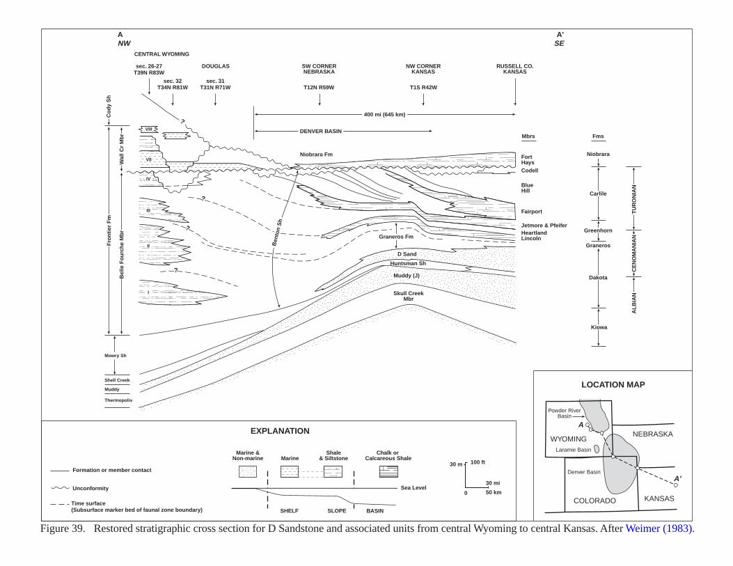
Mowry Sh
Muddy
Thermopolis
Shell Creek
Skull CreekMbr
Graneros Fm
Ben
ton
Sh
Muddy (J)
D Sand
Huntsman Sh
FortHaysCodell
BlueHill
Fairport
Jetmore & PfeiferHeartlandLincoln
Kiowa
Dakota
Graneros
Greenhorn
Carlile
CE
NO
MA
NIA
NT
UR
ON
IAN
AL
BIA
N
Niobrara
FmsMbrs
Niobrara Fm
Co
dy
Sh
Wal
l Cr
Mb
rB
elle
Fo
urc
he
Mb
r
Fro
nti
er F
m
?
?
?
?
100 ft30 m
0
30 mi
50 km
CENTRAL WYOMING
DOUGLAS SW CORNERNEBRASKA
NW CORNERKANSAS
RUSSELL CO.KANSAS
sec. 32T34N R81W
sec. 31T31N R71W T12N R59W T1S R42W
sec. 26-27T39N R83W
DENVER BASIN
400 mi (645 km)
ANW
A'SE
VIII
VII
IV
III
II
I
Formation or member contact
Time surface(Subsurface marker bed of faunal zone boundary)
Marine &Non-marine
Shale& SiltstoneMarine
Chalk or Calcareous Shale
Sea Level
SHELF SLOPE BASIN
EXPLANATION
LOCATION MAP
Unconformity
WYOMING
COLORADO
NEBRASKA
KANSAS
Laramie Basin
Denver Basin
Powder RiverBasin
A
A'
Figure 39. Restored stratigraphic cross section for D Sandstone and associated units from central Wyoming to central Kansas. After Weimer (1983).
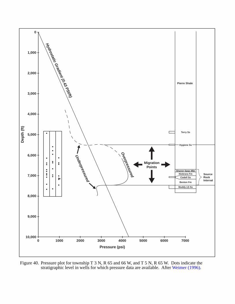
0 1000 2000 3000 4000 5000 6000 700010,000
9,000
8,000
7,000
6,000
5,000
4,000
3,000
2,000
1,000
0
Pressure (psi)
Dep
th (
ft)
Figure 40. Pressure plot for township T 3 N, R 65 and 66 W, and T 5 N, R 65 W. Dots indicate the stratigraphic level in wells for which pressure data are available. After Weimer (1996).
MigrationPoints
Hydrostatic G
radient (0.43 PSI/ft)
Overpressured
Underpressured
Sharon Spgs Mbr
Terry Ss
Hygiene Ss
Niobrara Fm
Codell Ss
Benton Fm
Muddy (J) Ss
Pierre Shale
SourceRockInterval
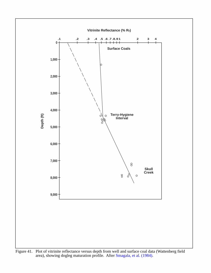
Dep
th (
ft)
Vitrinite Reflectance (% R0)
.1 .2 .3 .4 .5 .6 .7 .8.91 2 3 4
9,000
8,000
7,000
6,000
5,000
4,000
3,000
2,000
1,000
0
Figure 41. Plot of vitrinite reflectance versus depth from well and surface coal data (Wattenberg fieldarea), showing dogleg maturation profile. After Smagala, et al. (1984).
Terry-HygieneInterval
Surface Coals
SkullCreek
95
GREAT BASIN (TERTIARY BASINS)
GEOLOGIC SETTING
The Great Basin is part of the Basin and Range geologic province, which makes up most of Nevada. Figure 42shows the valleys in the province. The state has undergone complex geological and structural development. At leastfour major orogenies affected the area prior to the initiation of Basin and Range extension during the Miocene(Montgomery, 1988b). Uplift during the Antler orogeny (Late Devonian to Early Mississippian) created a north-south trending barrier, isolating a foreland basin to the east. Next, the Sonoma Orogeny (Late Permian through EarlyTriassic) emplaced the Golconda Allochthon in central Nevada. The Jurassic Nevadan Orogeny involved thrusting andfolding in the central part of the state and ended the marine sedimentation. The Sevier/Laramide episode (Late Jurassicthrough the Eocene) resulted in extensive volcanism throughout much of western and central Nevada, and creation ofthe Rocky Mountain Thrust Belt. Another period of extensive volcanism began in the Oligocene.
During the Paleozoic era and ending in the Permian, up to 50,000 feet of shallow water carbonate and clasticrocks were deposited (Peterson, 1988). From the Cretaceous through the Eocene, large lakes formed in the BlackRock Desert area and in the Carson Sink (Figure 42) and organic-rich rocks were deposited, including the Sheep PassFormation (Late Cretaceous–Eocene), the Newark Canyon Formation (Late Cretaceous), and the Elko Formation(Eocene–Oligocene). In southeast and northwest Nevada, large lakes formed during Miocene and Pliocene time(Barker, 1996a; Hastings, 1979). These lakes contain organic rich source rocks. Figure 43 shows stratigraphiccolumns for two areas in eastern Nevada.
Crustal extension began in the Miocene, forming characteristic Basin and Range structures: alternating horstsand grabens (Peterson, 1988). Extensional faulting continues to the present. Block faulting broke up the Sheep Pass,Newark Canyon and Elko Basins. Their lacustrine and clastic fluvial deposits subsided into deep grabens. Figure 44shows a cross section across Railroad Valley in east-central Nevada. Several present day valleys contain over 10,000feet of late Tertiary and Pleistocene fluvial, lacustrine and volcanic valley fill (Peterson, 1988). These Tertiarylacustrine deposits provided the source rock for several oil fields in Nevada. The Sheep Pass Formation provided bothsource and reservoir strata for Eagle Springs Field and source rocks for Trap Springs Fields in Railroad Valley(Figure 43).
HYDROCARBON PRODUCTION
There are 12 producing oil fields in Nevada at present. Reservoirs include the Garrett Ranch Volcanics, whichproduce at Trap Springs Field, and the Sheep Pass Formation, which produces at Eagle Springs Field. Mostexploration has been along the faulted valley margins.
All deep Tertiary basins will probably have at least one good source rock either in the basin, or subcroppingagainst the basin fill. Barker (1996a) states that Tertiary lacustrine shales and marls from six wells in the CarsonSink have a TOC range from 0.1 to 3.0%. The rocks have a hydrogen index over 400 mg/gram organic carbon andare oil prone. There is unusually high heat flow in the area. Strata buried only 3,300 to 6.600 ft deep during thePliocene may now be in the oil generation window.
96
EVIDENCE FOR BASIN-CENTERED GAS
Gas shows have occurred in many exploration wells, indicating some of these basins have generated gas. Deepsource rocks in the grabens probably lie on the gas-only generation window, because of high geothermal gradients.
The Tertiary Sheep Pass, Newark Canyon and Elko Formations are considered the most prospective forhydrocarbon generation, migration and trapping (Figure 43). There are other hydrocarbon source rocks in Nevada,including the Mississippian Chainman Shale, which in Railroad Valley is a partial source for the Eagle SpringsField and the main source for the Grant Canyon Field. These pre-Tertiary source rocks may have helped chargepossible basin-centered gas accumulations within the Tertiary graben valley fill.
Regional gravity data show several basins that contain thick Tertiary fill. The valley fill is less dense than theolder Paleozoic and Mesozoic strata that crop out in the bordering mountain ranges and form the basement in thegrabens. Jachens and Moring (1990) published gravity maps that show the thickness of Tertiary strata. Figure 45shows areas with pronounced residual gravity minima that may indicate thick Tertiary strata.
Several valleys in east-central Nevada have anomalously low gravity (Jachens and Moring, 1990). Tertiarylacustrine valleys are the most prospective for basin-centered gas. Their basin configurations are better known fromseismic data than are other Basin and Range valleys. Some valleys fall within a gravity low, but are not in easternNevada and so remain speculative for basin-centered gas.
The Carson Sink in Western Nevada does not fall within a gravity low, but seismic data indicates 11,000 ft ofTertiary fill, including organic-rich lacustrine source rocks (Barker, 1996a), and several exploration wells have gasshows.
KEY ACCUMULATION PARAMETERS
Identification Basin and Range Province; Cenozoic Speculative Basin Centered Gas Accumulation
Geologic Characterization of Accumulation:
a. Source/reservoir Organic-rich Tertiary lacustrine shales: Sheep Pass Fm (Paleocene-Eocene), Elko Fm (Paleocene), and Newark Canyon Fm (Cretaceous); several Paleozoic source rocks may also contribute hydrocarbons to this play
(Peterson, 1988): Chainman Shale (Mississippian), Pilot Shale (Upper Dev. - Lower Miss.), Carbon Ridge Fm (Permian); Webb Fm (Miss.), Woodruff Fm (Devonian), Slaven Chert (Devonian), and Vinini Fm (Ordovician)
All deep Tertiary basins will probably have at least one good source rock either in the basin, or subcropping against the basin fill. Barker (1996a) states that Tertiary lacustrine shales and marls from 6 wells in the Carson
Sink have a TOC range from 0.1 – 3.0%. The rocks have a hydrogen index over 400 mg/gram organic carbon and are oil prone. There is unusually high heat flow in the area. Strata buried only 1 to 2 km deep during the
Pliocene may now be in the oil generation window.b. Total Organic Carbons
(TOCs)Poole and Claypool (1984) report the following TOC values:
c. Thermal maturity The discovery of 12 producing oil and gas fields in Nevada, indicates that there are source rocks at depth which have generated hydrocarbons. In Railroad Valley, Poole and Claypool (1984) interpret thermally mature
conditions below 6,800 feet – extending from Eocene Sheep Pass Fm downward into the Mississippian Chainman Shale. Overmature source rocks are most likely to be a problem in the deepest parts of this play which may
have a Paleozoic source rock. For Eagle Springs Field, the initial BHT (Bottom Hole Temperature) was 200° F (93° C) at 6400 ft. The temperature gradient is 20 deg/1000 ft for the depth interval 6000 – 10,000 ft (Bortz and
Murray, 1979). The Carson Sink has a geothermal gradient of 25 deg/ 1000 ft (Hastings, 1979, p. 520).
Source System or Series Total Organic Carbon(TOC) (%)
Sheep Pass Fm .............................. Paleocene - Eocene................ ........ 3 - 4 avg, to 9.5 maxElko Fm ...................................... Eocene - Oligocene (?)........... ........ 33.5 - 38.8 (oil shale)Newark Canyon Fm ....................... Cretaceous........................... ........ to 5.66Chainman Shale ............................ Mississippian....................... ........ 2.3 - 3.84 avg, to 10.6 maxPilot Shale ................................... Upper Dev. - Lower Miss. ...... ........Carbon Ridge Fm .......................... Permian .............................. ........Webb Fm ..................................... Mississippian....................... ........ to 6.12Woodruff Fm................................ Devonian............................. ........ 5.7 avg to 13.9 maxSlaven Chert ................................. Devonian............................. ........Vinini Fm .................................... Ordovician........................... ........ 1 - 25Carson Sink.................................. Tertiary............................... ........ 0.1 - 3
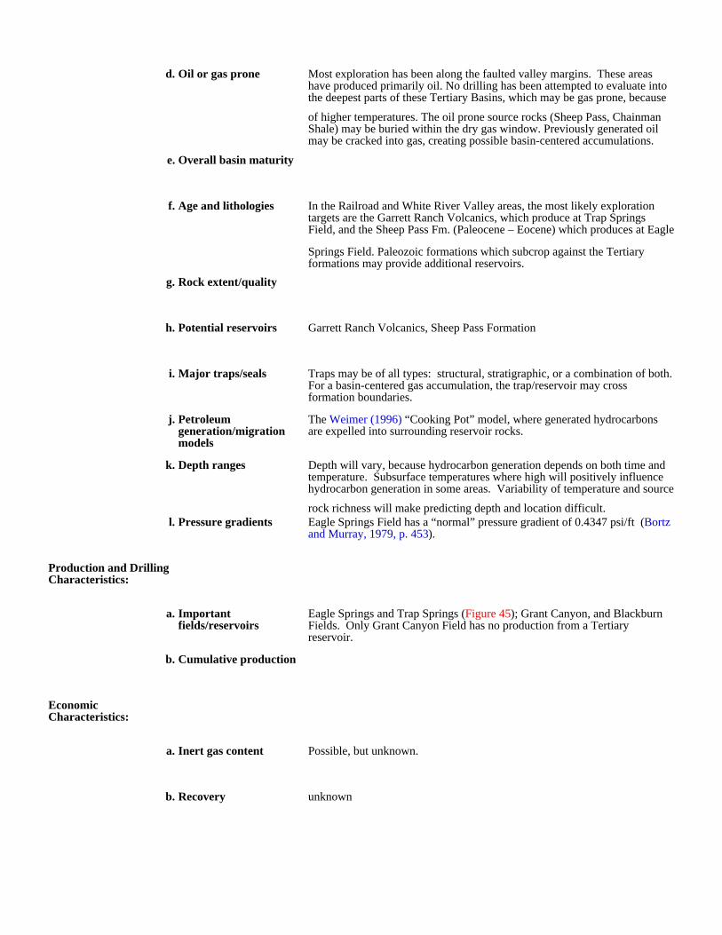
d. Oil or gas prone Most exploration has been along the faulted valley margins. These areas have produced primarily oil. No drilling has been attempted to evaluate into the deepest parts of these Tertiary Basins, which may be gas prone, because
of higher temperatures. The oil prone source rocks (Sheep Pass, Chainman Shale) may be buried within the dry gas window. Previously generated oil may be cracked into gas, creating possible basin-centered accumulations.
e. Overall basin maturity
f. Age and lithologies In the Railroad and White River Valley areas, the most likely exploration targets are the Garrett Ranch Volcanics, which produce at Trap Springs Field, and the Sheep Pass Fm. (Paleocene – Eocene) which produces at Eagle
Springs Field. Paleozoic formations which subcrop against the Tertiary formations may provide additional reservoirs.
g. Rock extent/quality
h. Potential reservoirs Garrett Ranch Volcanics, Sheep Pass Formation
i. Major traps/seals Traps may be of all types: structural, stratigraphic, or a combination of both. For a basin-centered gas accumulation, the trap/reservoir may cross formation boundaries.
j. Petroleum generation/migration models
The Weimer (1996) “Cooking Pot” model, where generated hydrocarbons are expelled into surrounding reservoir rocks.
k. Depth ranges Depth will vary, because hydrocarbon generation depends on both time and temperature. Subsurface temperatures where high will positively influence hydrocarbon generation in some areas. Variability of temperature and source
rock richness will make predicting depth and location difficult.l. Pressure gradients Eagle Springs Field has a “normal” pressure gradient of 0.4347 psi/ft (Bortz
and Murray, 1979, p. 453).
Production and Drilling Characteristics:
a. Important fields/reservoirs
Eagle Springs and Trap Springs (Figure 45); Grant Canyon, and Blackburn Fields. Only Grant Canyon Field has no production from a Tertiary reservoir.
b. Cumulative production
Economic Characteristics:
a. Inert gas content Possible, but unknown.
b. Recovery unknown

c. Pipeline infrastructure There are no gas pipelines through the Eastern play area. A 16-inch natural gas pipeline enters Nevada just east of the Oregon border end runs southwest through Winnemucca and then along Interstate Highway I-80, through the
northern part of the Carson Sink Basin to Reno. The pipeline continues through Carson City, then exits Nevada into California. An 8-inch trunk line runs east to Elko from Winnemucca, and a second 8-inch trunk line runs east
east from north of Reno, along Highway US 50 to Frenchman.d. Exploration maturity
relative to other basinsAlthough there are presently 12 producing oil fields in Nevada, the state is still a high-risk, under-drilled immature exploration area.
e. Sediment consolidation Unknown, but poor consolidation has not been a serious problem in wells drilled through the Tertiary section.
f. Porosity/completion problems
Unknown, low porosity and fracture production are expected in this play, both of which may cause drilling and completion problems.
g. Permeability
h. Porosity
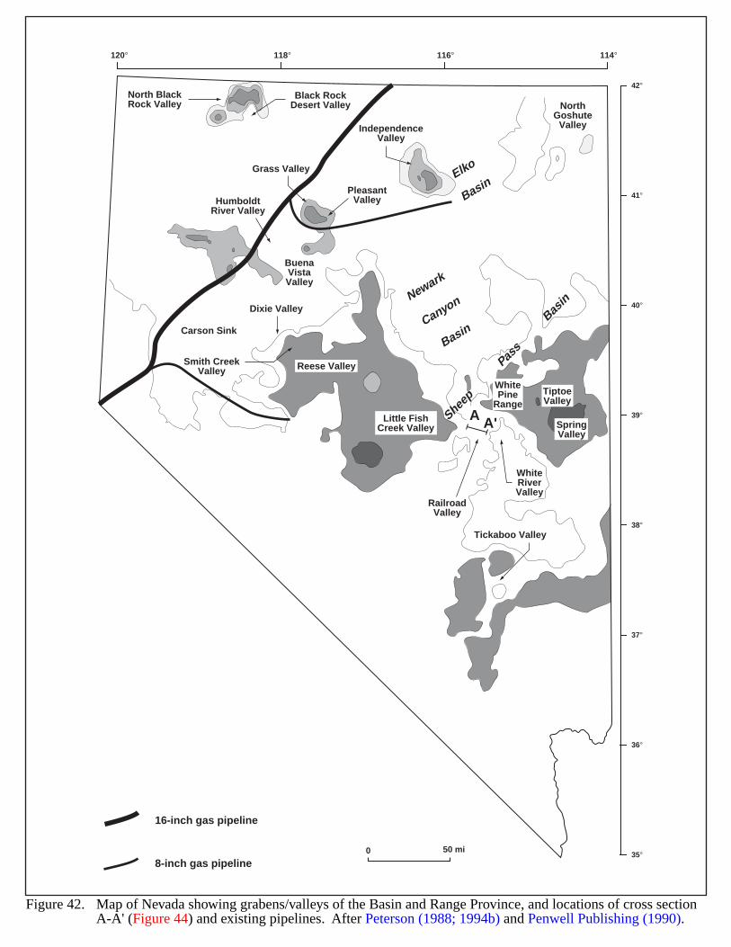
42°
41°
40°
39°
38°
37°
36°
35°
120° 118° 116° 114°
HumboldtRiver Valley
Carson Sink
North BlackRock Valley
Black RockDesert Valley
IndependenceValley
NorthGoshute
Valley
Dixie Valley
Smith CreekValley Reese Valley
Little FishCreek Valley
RailroadValley
Tickaboo Valley
SpringValley
TiptoeValley
BuenaVistaValley
Grass Valley
PleasantValley
WhiteRiverValley
A A'
WhitePine
Range
Newark
Canyon
Basin
Elko
Basin
Sheep
Pass
Bas
in
0 50 mi
Figure 42. Map of Nevada showing grabens/valleys of the Basin and Range Province, and locations of cross section A-A' (Figure 44) and existing pipelines. After Peterson (1988; 1994b) and Penwell Publishing (1990).
16-inch gas pipeline
8-inch gas pipeline
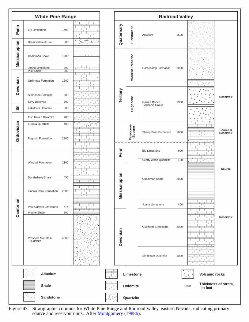
Figure 43. Stratigraphic columns for White Pine Range and Railroad Valley, eastern Nevada, indicating primary source and reservoir units. After Montgomery (1988b).
Pen
n
Qu
ater
nar
y
Ple
isto
cen
eM
ioce
ne-
Plio
cen
eO
ligo
cen
eP
aleo
cen
e-E
oce
ne
Tert
iary
Pen
nM
issi
ssip
pia
nD
evo
nia
n
Mis
siss
ipp
ian
White Pine Range Railroad ValleyD
evo
nia
nS
ilO
rdov
icia
nC
amb
rian
Ely Limestone 1600'
Dramond Peak Fm 600'
Chainman Shale 1900'
Joana Limestone 200'Pilot Shale 200'
Guilmette Formation 1600'
Simonson Dolomite 900'
Sevy Dolomite 300'
Laketown Dolomite 800'
Fish Haven Dolomite 700'
Eureka Quartzite 400'
Pogonip Formation 2200'
Windfall Formation 2100'
Dunderberg Shale 450'
Lincoln Peak Formation 2000'
Pole Canyon Limestone 675'
Pioche Shale 300'
Prospect Mountain Quartzite
4500'
Alluvium
Reservoir
Source &Reservoir
Source
Reservoir
1500'
Horsecamp Formation 2000'
Sheep Pass Formation 1000'
Ely Limestone 900'
Scotty Wash Quartzite 160'
Chainman Shale 2000'
Joana Limestone 400'
Guilmette Limestone 2000'
Simonson Dolomite 1000'
Garrett Ranch Volcanic Group
1900'
Alluvium
Shale
Sandstone
Limestone Volcanic rocks
Dolomite Thickness of strata, in feet
Quartzite
1900'
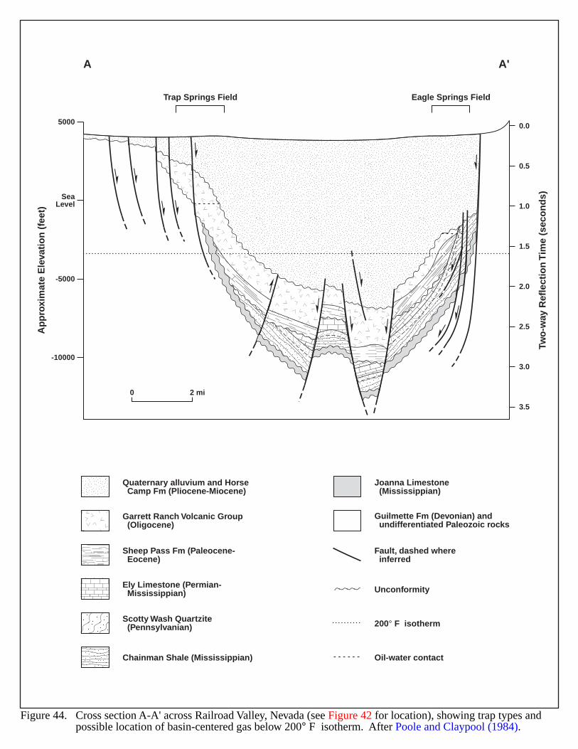
5000
SeaLevel
-5000
-10000
0.0
0.5
1.0
1.5
2.0
2.5
3.0
3.5
A A'
Ap
pro
xim
ate
Ele
vati
on
(fe
et)
Two
-way
Ref
lect
ion
Tim
e (s
eco
nd
s)
Trap Springs Field Eagle Springs Field
0 2 mi
Chainman Shale (Mississippian)
Sheep Pass Fm (Paleocene- Eocene)
Ely Limestone (Permian- Mississippian)
Scotty Wash Quartzite (Pennsylvanian)
Garrett Ranch Volcanic Group (Oligocene)
Oil-water contact
Quaternary alluvium and Horse Camp Fm (Pliocene-Miocene)
Joanna Limestone (Mississippian)
Unconformity
200° F isotherm
Fault, dashed where inferred
Guilmette Fm (Devonian) and undifferentiated Paleozoic rocks
Figure 44. Cross section A-A' across Railroad Valley, Nevada (see Figure 42 for location), showing trap types and possible location of basin-centered gas below 200° F isotherm. After Poole and Claypool (1984).
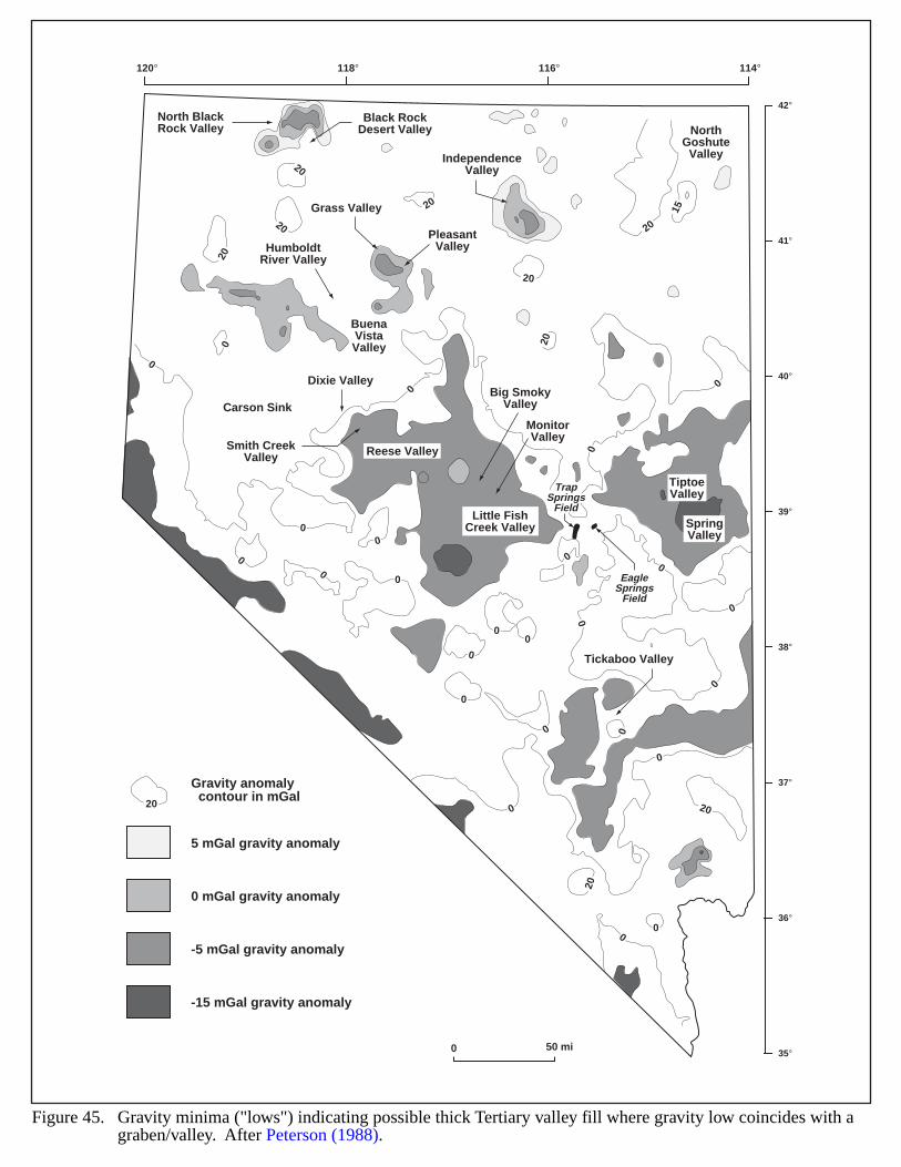
20
20
20
20
20
2020
20
15
20
0
0
0
0
00
0
0
0
00
0
0
0
0
0
00
0
0
0
0
0
0
0
42°
41°
40°
39°
38°
37°
36°
35°
120° 118° 116° 114°
HumboldtRiver Valley
Carson Sink
North BlackRock Valley
Black RockDesert Valley
IndependenceValley
NorthGoshute
Valley
Dixie Valley
Smith CreekValley Reese Valley
Big SmokyValley
MonitorValley
Little FishCreek Valley
Tickaboo Valley
SpringValley
TiptoeValley
BuenaVistaValley
Grass Valley
PleasantValley
TrapSprings
Field
EagleSprings
Field
0 50 mi
5 mGal gravity anomaly
0 mGal gravity anomaly
-5 mGal gravity anomaly
-15 mGal gravity anomaly
Gravity anomaly contour in mGal
20
Figure 45. Gravity minima ("lows") indicating possible thick Tertiary valley fill where gravity low coincides with agraben/valley. After Peterson (1988).
104
GULF COAST–AUSTIN CHALK
GEOLOGIC SETTING
The Late Cretaceous Austin Chalk of the Gulf Coast was deposited in shallow water on the stable, gentlydipping shelf of the Gulf Basin. The limits of deposition were from the present outcrop belt to the sharp break of theCretaceous shelf edge (Figure 46). The Chalk overlies the shales of the Eagle Ford formation and is unconformablyoverlain by the Taylor Group (Figure 47) The dominant lithology is carbonate skeletal debris with some bands ofclay, shale and organic-rich marl. The Chalk becomes increasingly shaley basinward and grades into the shales of theunderlying Eagle Ford. Thickness increases downdip from less than 100 ft near the outcrop to over 650 ft at depthsof 9,500 ft. Thickness also varies along strike reflecting variations in the shelf. In the Maverick Basin (Rio GrandeEmbayment), the Chalk exceeds 1,000 ft thickness, thins at comparable depth across the San Marcos Arch, andthickens again in the East Texas Basin.
Most structure observed in the Chalk reflects an extensional structural style related to opening of the Gulf Basin.Locally, structure may be complex, influenced by salt flow, anticlinal growth or drape related to differentialcompaction in underlying sediments.
HYDROCARBON PRODUCTION
The Austin Chalk has yielded oil and gas in both Texas and Louisiana for over 70 years. Development in Texasoccurs in a 30 mile wide band that stretches from the Rio Grande in south Texas to the Louisiana state line.
Austin Chalk production in Louisiana had been limited to the central part of the state and was incidental todeeper exploration. The successful application of horizontal drilling at Brookeland field in Sabine County, eastTexas, led to the first successful drilling for the Chalk in western Louisiana. At the same time, operators in existingfields of Avoyelles Parish began to apply horizontal drilling to exploit Austin Chalk reserves.
The Chalk in Louisiana generally produces from greater depths than in Texas. At Jack Moncrief and NorthBayou fields, the Chalk produces high-GOR oil (oil ranging from 39° to 42.7° API gravity) from depths of about14,500 ft. Farther west at Masters Creek field, the Chalk produces condensate and gas from 14,800 ft. These depthsyield dry gas at Giddings. This change in hydrocarbon charge may be related to a southeast to northwest shift ingeothermal gradient (Pollastro, U.S. Geological Survey, 1999, personal communication). Work on the geographicdistribution of geothermal gradients in the Chalk remains incomplete, but will add substantially to understandinghydrocarbon generation beyond the models proposed in the Texas fairway.
The Chalk produces from natural fractures. Consequently, most of the production is associated with known faultzones or other structural features responsible for fracture development (Stapp, 1977). Locally, high fluid porepressure may have contributed to fracturing (Corbett et al., 1987). Gas expansion is the principal driving mechanismin the reservoirs. Gas to oil ratios generally show an inverse relationship to structural position; that is, gas richreservoirs tend to be structurally lower while oil rich reservoirs are shallower. This reflects increased generation ofgas at greater depth (Figure 48) Reservoirs are directly related to the amount of fracturing; this prevents extensivemigration and most hydrocarbons stay near the depths at which they were generated. Thin bentonite or shale bedslimit vertical fracture growth. Different horizons are productive in different geographical areas. Upper benches of theChalk are productive at Pearsall field in the western area; the lowermost Bench is the pay at the Giddings Area.Farther east at Brookeland field and in Louisiana, the clay/shale interbeds are absent and the Chalk may be fracturedfor its entire height. The source for Austin Chalk accumulations may be the underlying Eagle Ford shales or bycarbonaceous beds within the Chalk itself (Stapp, 1977; Grabowski, 1981, 1984; Ewing, 1983; Hinds and Berg,1990).
Fracture production is characterized by high initial rates of production as open fracture systems are drained.Production declines are very rapid and are followed by extended periods of low volume production, as microfracturesand/or matrix permeability produce fluid to the open fractures penetrated by the wellbore.
105
EVIDENCE FOR BASIN-CENTERED GAS
The discovery of dry (non-associated) gas at the Giddings Deep field in Texas is of particular importance forexploration for other dry gas accumulations in the Austin Chalk. The Austin Chalk has generally been regarded as anoil play and certainly the drilling cycles of the 1970s and 1990s were driven by higher oil prices as well as technicaladvances. With an abundance of conventional and non-conventional gas plays in Texas, there has been little incentivefor operators to drill the deeper, increasingly shaley Chalk in search of gas reserves, especially since the chalk wasassumed to shale out at depths suitable for gas generation. Gas/oil ratios are relatively constant within most fieldsbut at Giddings are known to increase about 10 fold across the field. Deep drilling was a deliberate effort to establishgas reserves. The deeper drilling also identified chalk lithology at greater depths than had previously been expected(Pollastro, U.S. Geological Survey, 1999, personal communication).
The Austin Chalk apparently can produce commercial gas at Giddings field in Texas. Local drilling at Giddingshas extended the Chalk play downdip past its previously assumed limits. The extension of Chalk exploration intoLouisiana has identified areas of gas and condensate production. Areas including east Texas, and western and southernLouisiana may be the best area for future gas development. Potential exists for westward extension of the playdowndip of the oil producing trend. The presence of clean chalk beyond its currently assumed limits at the Cretaceousshelf edge will be a determining factor. Also necessary are fracturing mechanisms to produce reservoirs. The presenceof source beds within the Chalk and the underlying Eagle Ford shale insure gas generation at sufficient depth andtemperature. Salt flow, regional dip change, and faulting associated with flexure of the Cretaceous shelf edge couldall contribute to fracture development.
1) The Austin Chalk and the underlying Eagle Ford shale are sufficiently mature for gas and gas-condensategeneration throughout the known extent of the play. The Chalk appears to be gas-prone at shallower depthsin the western portion of the play in Texas.
2) Clean, brittle chalk suitable for fracturing is present at depths of gas generation in east Texas and eastwardinto Louisiana. The downdip limits at which the chalk grades to shale in this area are not yet fullyestablished.
3) Fractures within the Chalk constitute the reservoir; therefore, reservoirs become limited to areas offracturing. In this respect the Austin Chalk differs from a typical continuous gas accumulation. Althoughgas may be present in the chalk matrix, fracture permeability is necessary for production. Thus, the extentof fracturing will restrict formation of gas-producing reservoirs. Salt flow, faulting, differential compaction,and other structural or stratigraphic events can create fracturing throughout the known extent of the play.Fracture trends may be identified regionally, but fracturing suitable for reservoir development will be limitedlocally.
4) Temperatures in the deep Chalk play reach 350 °F at Giddings field in Texas. The geothermal gradientapparently changes in Louisiana from northwest to southeast and appears to match the shift from gas-pronereservoirs to high-GOR oil reservoirs. The nature and extent of this change is not understood. A betterunderstanding of this phenomenon might help identify gas-prone Austin Chalk in the eastern part of theplay.
5) The only significant water production in the deep Chalk play is at Masters Creek field in Louisiana, wherethe Chalk is in fracture communication with the underlying geopressured Eagle Ford Formation.
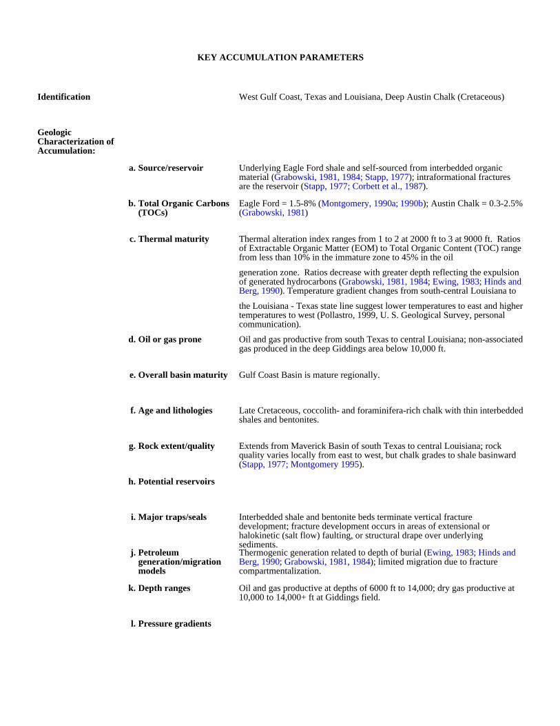
KEY ACCUMULATION PARAMETERS
Identification West Gulf Coast, Texas and Louisiana, Deep Austin Chalk (Cretaceous)
Geologic Characterization of Accumulation:
a. Source/reservoir Underlying Eagle Ford shale and self-sourced from interbedded organic material (Grabowski, 1981, 1984; Stapp, 1977); intraformational fractures are the reservoir (Stapp, 1977; Corbett et al., 1987).
b. Total Organic Carbons (TOCs)
Eagle Ford = 1.5-8% (Montgomery, 1990a; 1990b); Austin Chalk = 0.3-2.5% (Grabowski, 1981)
c. Thermal maturity Thermal alteration index ranges from 1 to 2 at 2000 ft to 3 at 9000 ft. Ratios of Extractable Organic Matter (EOM) to Total Organic Content (TOC) range from less than 10% in the immature zone to 45% in the oil
generation zone. Ratios decrease with greater depth reflecting the expulsion of generated hydrocarbons (Grabowski, 1981, 1984; Ewing, 1983; Hinds and Berg, 1990). Temperature gradient changes from south-central Louisiana to
the Louisiana - Texas state line suggest lower temperatures to east and higher temperatures to west (Pollastro, 1999, U. S. Geological Survey, personal communication).
d. Oil or gas prone Oil and gas productive from south Texas to central Louisiana; non-associated gas produced in the deep Giddings area below 10,000 ft.
e. Overall basin maturity Gulf Coast Basin is mature regionally.
f. Age and lithologies Late Cretaceous, coccolith- and foraminifera-rich chalk with thin interbedded shales and bentonites.
g. Rock extent/quality Extends from Maverick Basin of south Texas to central Louisiana; rock quality varies locally from east to west, but chalk grades to shale basinward (Stapp, 1977; Montgomery 1995).
h. Potential reservoirs
i. Major traps/seals Interbedded shale and bentonite beds terminate vertical fracture development; fracture development occurs in areas of extensional or halokinetic (salt flow) faulting, or structural drape over underlying sediments.
j. Petroleum generation/migration models
Thermogenic generation related to depth of burial (Ewing, 1983; Hinds and Berg, 1990; Grabowski, 1981, 1984); limited migration due to fracture compartmentalization.
k. Depth ranges Oil and gas productive at depths of 6000 ft to 14,000; dry gas productive at 10,000 to 14,000+ ft at Giddings field.
l. Pressure gradients
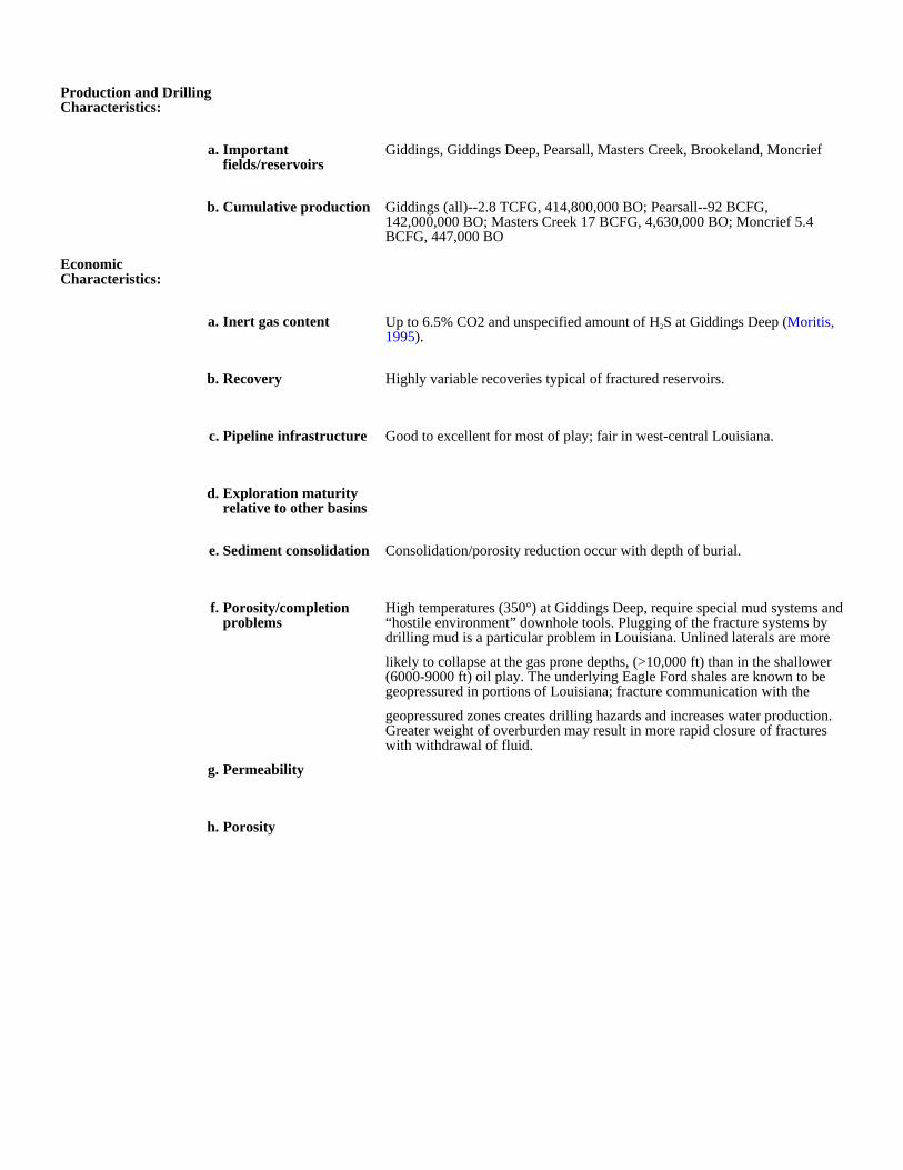
Production and Drilling Characteristics:
a. Important fields/reservoirs
Giddings, Giddings Deep, Pearsall, Masters Creek, Brookeland, Moncrief
b. Cumulative production Giddings (all)--2.8 TCFG, 414,800,000 BO; Pearsall--92 BCFG, 142,000,000 BO; Masters Creek 17 BCFG, 4,630,000 BO; Moncrief 5.4 BCFG, 447,000 BO
Economic Characteristics:
a. Inert gas content Up to 6.5% CO2 and unspecified amount of H2S at Giddings Deep (Moritis, 1995).
b. Recovery Highly variable recoveries typical of fractured reservoirs.
c. Pipeline infrastructure Good to excellent for most of play; fair in west-central Louisiana.
d. Exploration maturity relative to other basins
e. Sediment consolidation Consolidation/porosity reduction occur with depth of burial.
f. Porosity/completion problems
High temperatures (350°) at Giddings Deep, require special mud systems and “hostile environment” downhole tools. Plugging of the fracture systems by drilling mud is a particular problem in Louisiana. Unlined laterals are more
likely to collapse at the gas prone depths, (>10,000 ft) than in the shallower (6000-9000 ft) oil play. The underlying Eagle Ford shales are known to be geopressured in portions of Louisiana; fracture communication with the
geopressured zones creates drilling hazards and increases water production. Greater weight of overburden may result in more rapid closure of fractures with withdrawal of fluid.
g. Permeability
h. Porosity
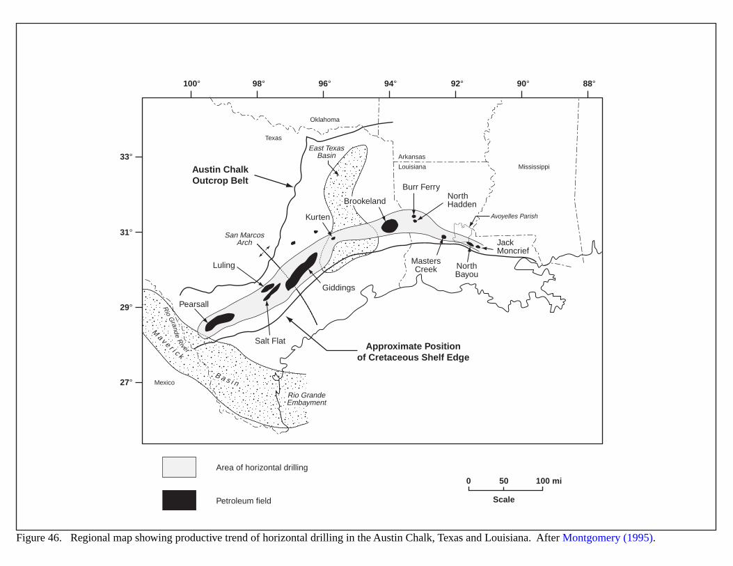
Texas
Oklahoma
Mexico
Arkansas
Louisiana MississippiAustin ChalkOutcrop Belt
Approximate Positionof Cretaceous Shelf Edge
East TexasBasin
San MarcosArch
Rio GrandeEmbayment
Rio
Grande
River
Ma v e r i c k
B a s i n
Pearsall
Giddings
Kurten
Burr Ferry
JackMoncrief
NorthHadden
MastersCreek North
BayouLuling
Salt Flat
Brookeland
Avoyelles Parish
100°
33°
31°
29°
27°
98° 96° 94° 92° 90° 88°
0 50 100 mi
Scale
Figure 46. Regional map showing productive trend of horizontal drilling in the Austin Chalk, Texas and Louisiana. After Montgomery (1995).
Area of horizontal drilling
Petroleum field
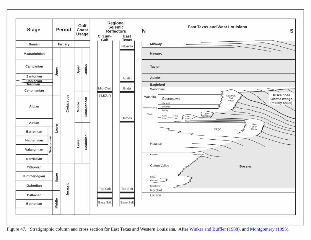
Stage
Danian Tertiary
Circum-Gulf
EastTexas
Midway
Navarro
Austin
Washita
Sligo
Fredericksburg
Knowles
Gilmer
Buckner
Smackover
Shelf Margin
Trinity
Stuart CityShelf
Margin
SligoShelf
Margin
EaglefordWoodbine
Hosston
Cotton Valley
Norphet
Louann
Bossier
GeorgetownKiamichi
Edwards
Paluxy
GlenRose
FerryLake
Taylor
Navarro
Austin
Buda
James
Top SaltTop Salt
Base SaltBase Salt
Mid-Cret.
("MCU")
Cre
tace
ou
sJu
rass
ic
Up
per
Up
per
Mid
dle
Lo
wer
Up
per
Gu
lfia
nC
om
anch
ean
Co
ahu
ilan
Mid
dle
Lo
wer
Neo
com
ian
Maastrichtian
Campanian
SantonianConiacianTuronian
Cenomanian
Albian
Aptian
Barremian
Hauterivian
Valanginian
Berriasian
Tithonian
Kimmeridgian
Oxfordian
Callovian
Bathonian
PeriodGulf
CoastUsage
RegionalSeismic
ReflectorsEast Texas and West Louisiana
N S
LowerGlenRose
UpperGlen Rose
Pearsall
TuscaloosaClastic wedge(mostly shale)
Figure 47. Stratigraphic column and cross section for East Texas and Western Louisiana. After Winker and Buffler (1988), and Montgomery (1995).
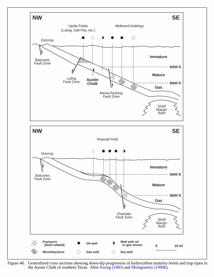
6000 ft
9000 ft
NW SE
NW SE
Updip Fields(Luling, Salt Flat, etc.)
Midtrend-Giddings
Outcrop
BalconesFault Zone
LulingFault Zone
ShelfMarginReef
Mexia-FashingFault Zone
Immature
MatureAustinChalk
Gas
6000 ft
9000 ft
Pearsall Field
Outcrop
BalconesFault Zone
ShelfMarginReef
CharlotteFault Zone
Immature
Mature
Gas
Figure 48. Generalized cross sections showing down-dip progression of hydrocarbon maturity levels and trap types inthe Austin Chalk of southern Texas. After Ewing (1983) and Montgomery (1990b).
0 10 miFractures (fault-related)
Well with oil or gas shows
Microfractures
Oil well
Gas well Dry well
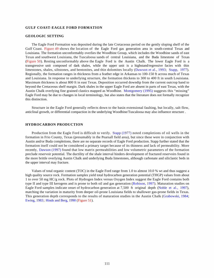
111
GULF COAST-EAGLE FORD FORMATION
GEOLOGIC SETTING
The Eagle Ford Formation was deposited during the late Cretaceous period on the gently sloping shelf of theGulf Coast. Figure 49 shows the location of the Eagle Ford gas generation area in south-central Texas andLouisiana. The formation unconformably overlies the Woodbine Group, which includes the Woodbine sands of eastTexas and southwest Louisiana, the Tuscaloosa sands of central Louisiana, and the Buda limestone of Texas(Figure 50). Resting unconformably above the Eagle Ford is the Austin Chalk. The lower Eagle Ford is atransgressive unit composed of dark shales, while the upper unit is a highstand/regressive facies with thinlimestones, shales, siltstones, and bentonites, and thin dolomites locally (Dawson et al., 1993; Stapp, 1977).Regionally, the formation ranges in thickness from a feather edge in Arkansas to 100-150 ft across much of Texasand Louisiana. In response to underlying structure, the formation thickens to 300 to 400 ft in south Louisiana.Maximum thickness is about 800 ft in east Texas. Deposition occurred downdip from the current outcrop band tobeyond the Cretaceous shelf margin. Dark shales in the upper Eagle Ford are absent in parts of east Texas, with theAustin Chalk overlying fine grained clastics mapped as Woodbine. Montgomery (1995) suggests this “missing”Eagle Ford may be due to changes in local terminology, but also states that the literature does not formally recognizethis distinction.
Structure in the Eagle Ford generally reflects down to the basin extensional faulting, but locally, salt flow,anticlinal growth, or differential compaction in the underlying Woodbine/Tuscaloosa may also influence structure .
HYDROCARBON PRODUCTION
Production from the Eagle Ford is difficult to verify. Stapp (1977) noted completions of oil wells in theformation in Frio County, Texas (presumably in the Pearsall field area), but since these were in conjunction withAustin and/or Buda completions, there are no separate records of Eagle Ford production. Stapp further stated that theformation itself could not be considered a primary target because of its thinness and lack of permeability. Morerecently, Dawson (1997) found that low matrix permeabilities and low volumetric parameters of the formationpreclude reservoir potential. The ductility of the shale interval hinders development of fractured reservoirs found inthe more brittle overlying Austin Chalk and underlying Buda limestones, although carbonate and siliclastic beds inthe upper interval may fracture.
Values of total organic content (TOC) in the Eagle Ford range from 1.0 to almost 10.0 % wt and thus suggest ahigh quality source rock. Formation samples yield total hydrocarbon generation potential (THGP) values from about1 to over 50 mg HC/g rock. Plots of Hydrogen Index versus Oxygen Index suggest the Eagle Ford contains bothtype II and type III kerogens and is prone to both oil and gas generation (Robison, 1997). Maturation studies onEagle Ford samples indicate onset of hydrocarbon generation at 7,500 ft original depth (Noble et al., 1997),matching the variation in maturity from deeper oil-prone Louisiana fields to shallower gas-prone fields in Texas.This generation depth corresponds to the results of maturation studies in the Austin Chalk (Grabowski, 1984;Ewing, 1983; Hinds and Berg, 1990 (Figure 51).
112
EVIDENCE OF BASIN-CENTERED GAS
The lack of verifiable production history and reported lack of reservoir make the Eagle Ford a poor candidate forsignificant gas accumulations. The similarity to maturity in the Austin Chalk allows extrapolation from Austin orTuscaloosa gas production to likely areas and depths of gas generation in the Eagle Ford. As a regionally extensiveorganic rich source rock, the Eagle Ford could generate gas over a large area downdip from the traditional AustinChalk oil trend and in the vicinity of deep dry-gas and gas-condensate production in the Giddings area of Texas andsouthwest Louisiana. Production of such gas will require the development of fracture reservoirs in the Chalk or theunderlying Buda formation. The Woodbine sands of eastern Texas grade basinward to shale; the Tuscaloosa sands ofsouthern Louisiana probably grade likewise. The Tuscaloosa-Eagle Ford transition occurs at depths greater than18,000 ft, a depth suitable for gas generation. The migration of such gas to conventional reservoirs would requirefaulting or fracturing (Montgomery, 1995). A widespread accumulation of gas in tight, silty Tuscaloosa sands in thetransition zone is possible but speculative. Any such accumulation would be within the area of geopressuring in theTuscaloosa, which would create drilling and completion problems.
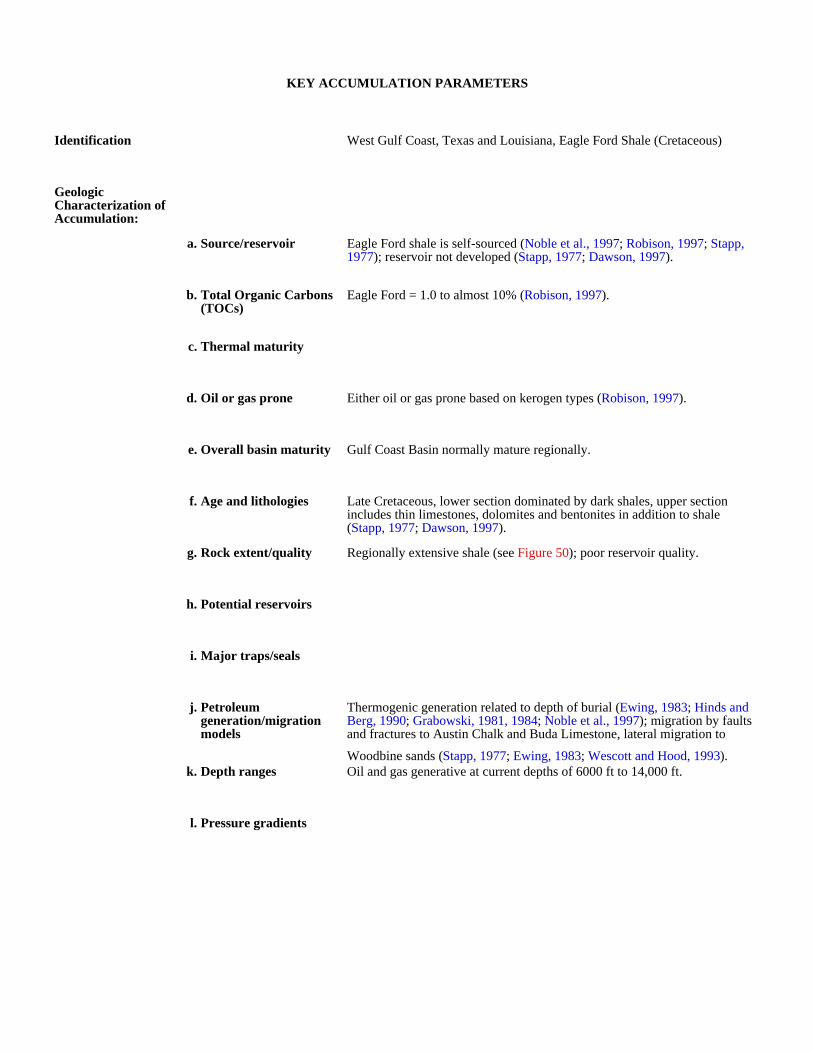
KEY ACCUMULATION PARAMETERS
Identification West Gulf Coast, Texas and Louisiana, Eagle Ford Shale (Cretaceous)
Geologic Characterization of Accumulation:
a. Source/reservoir Eagle Ford shale is self-sourced (Noble et al., 1997; Robison, 1997; Stapp, 1977); reservoir not developed (Stapp, 1977; Dawson, 1997).
b. Total Organic Carbons (TOCs)
Eagle Ford = 1.0 to almost 10% (Robison, 1997).
c. Thermal maturity
d. Oil or gas prone Either oil or gas prone based on kerogen types (Robison, 1997).
e. Overall basin maturity Gulf Coast Basin normally mature regionally.
f. Age and lithologies Late Cretaceous, lower section dominated by dark shales, upper section includes thin limestones, dolomites and bentonites in addition to shale (Stapp, 1977; Dawson, 1997).
g. Rock extent/quality Regionally extensive shale (see Figure 50); poor reservoir quality.
h. Potential reservoirs
i. Major traps/seals
j. Petroleum generation/migration models
Thermogenic generation related to depth of burial (Ewing, 1983; Hinds and Berg, 1990; Grabowski, 1981, 1984; Noble et al., 1997); migration by faults and fractures to Austin Chalk and Buda Limestone, lateral migration to
Woodbine sands (Stapp, 1977; Ewing, 1983; Wescott and Hood, 1993).k. Depth ranges Oil and gas generative at current depths of 6000 ft to 14,000 ft.
l. Pressure gradients

Production and Drilling Characteristics:
Not applicable
a. Important fields/reservoirs
b. Cumulative production
Economic Characteristics:
Not applicable; source rock only.
a. Inert gas content
b. Recovery
c. Pipeline infrastructure
d. Exploration maturity relative to other basins
e. Sediment consolidation
f. Porosity/completion problems
g. Permeability
h. Porosity
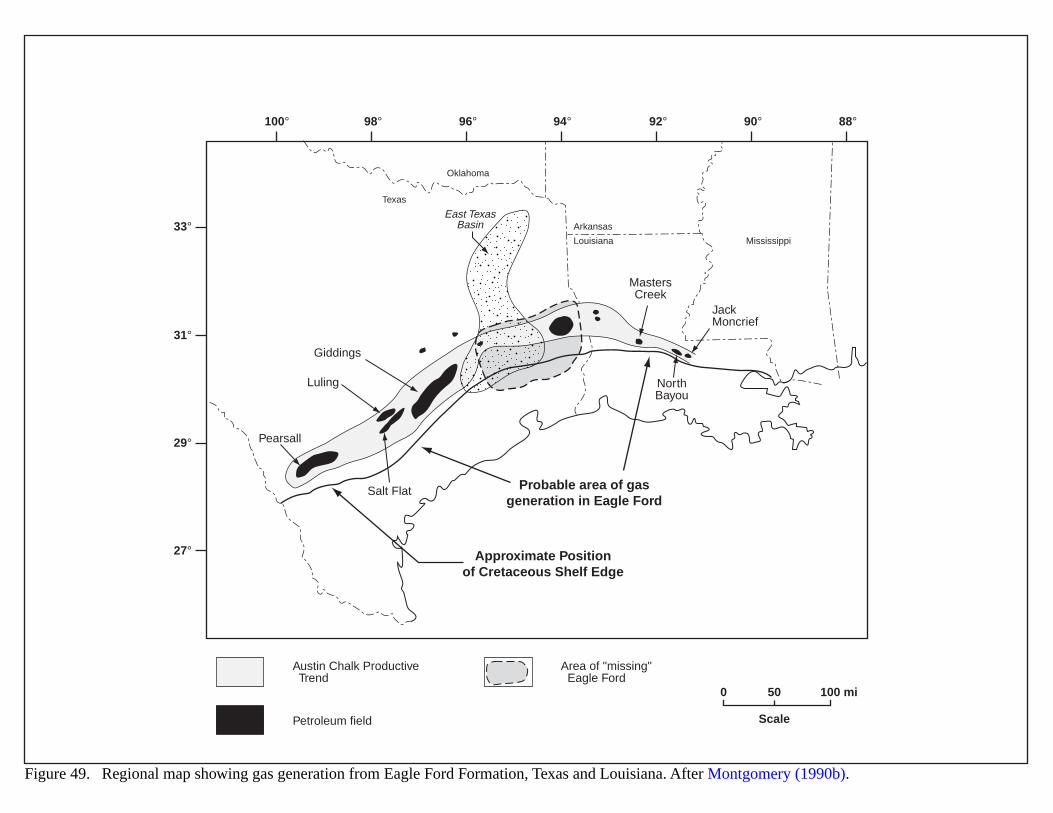
Texas
Oklahoma
Arkansas
Louisiana Mississippi
Probable area of gasgeneration in Eagle Ford
Pearsall
Giddings
JackMoncrief
MastersCreek
NorthBayou
East TexasBasin
Luling
Salt Flat
Approximate Positionof Cretaceous Shelf Edge
100°
33°
31°
29°
27°
98° 96° 94° 92° 90° 88°
0 50 100 mi
Scale
Figure 49. Regional map showing gas generation from Eagle Ford Formation, Texas and Louisiana. After Montgomery (1990b).
Austin Chalk Productive Trend
Area of "missing" Eagle Ford
Petroleum field
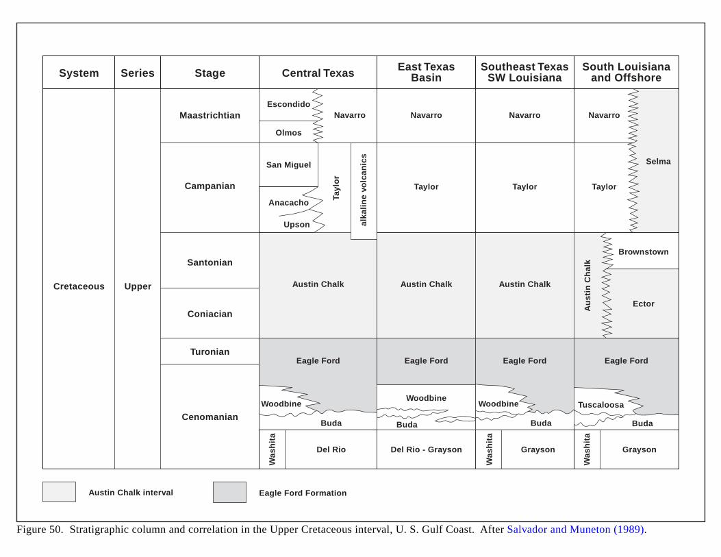
Cretaceous
System Series Stage Central Texas East TexasBasin
Southeast TexasSW Louisiana
South Louisianaand Offshore
Upper
MaastrichtianEscondido
Navarro Navarro
Taylor
Tayl
or
alka
lin
e vo
lcan
ics
Olmos
San Miguel
Anacacho
Upson
Austin Chalk Austin Chalk
Eagle Ford Eagle Ford
Navarro
Taylor
Navarro
Selma
Ector
Brownstown
Taylor
Austin Chalk
Au
stin
Ch
alk
Eagle Ford Eagle Ford
Buda Buda Buda Buda
Del Rio Del Rio - Grayson
Was
hit
a
Grayson
Was
hit
a
Grayson
Was
hit
a
Woodbine Woodbine TuscaloosaWoodbine
Campanian
Santonian
Coniacian
Turonian
Cenomanian
Figure 50. Stratigraphic column and correlation in the Upper Cretaceous interval, U. S. Gulf Coast. After Salvador and Muneton (1989).
Austin Chalk interval Eagle Ford Formation
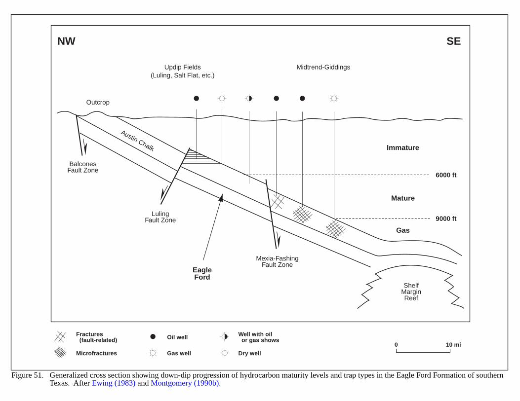
6000 ft
9000 ft
NW SE
Updip Fields(Luling, Salt Flat, etc.)
Midtrend-Giddings
Outcrop
BalconesFault Zone
LulingFault Zone
Austin Chalk
ShelfMarginReef
Mexia-FashingFault Zone
Immature
Mature
EagleFord
Gas
Figure 51. Generalized cross section showing down-dip progression of hydrocarbon maturity levels and trap types in the Eagle Ford Formation of southernTexas. After Ewing (1983) and Montgomery (1990b).
0 10 mi
Fractures (fault-related)
Well with oil or gas shows
Microfractures
Oil well
Gas well Dry well
118
GULF COAST-TRAVIS PEAK/COTTON VALLEY FORMATIONS
GEOLOGIC SETTING
The Lower Cretaceous Travis Peak Formation and Upper Jurassic Cotton Valley Group contain FERC-designated tight gas sands that were widely deposited across eastern Texas, northern Louisiana and into theMississippi salt basin (Figure 52). The lower part of the Cotton Valley also contains both reef-forming carbonatesand oolitic shoals. Sandstone distribution in the Cotton Valley generally is more consistent than that in the TravisPeak.
In east Texas, Travis Peak deposition occurred in a fluvial-deltaic environment that prograded from the northwest(Bushaw, 1968; Saucier, 1985; and Tye, 1989). Underlying Cotton Valley sands may be barrier-island type deposits.Interpretations of stratigraphic sequence have defined a number of depositional sub-environments (Figure 53) in eastTexas and western Louisiana that consist of:
1. a braided to meandering fluvial system;
2. interbedded deltaic/fluvial deposits–fluvial deposits distally become encased in deltaic rocks;
3. paralic deposits that interfinger with the above two systems near the top of the Travis Peak; and
4. shelf deposits near the downdip edge of the Travis Peak; these sediments interfinger with and onlap deltaicand paralic deposits (Dutton et al., 1993).
Thickness of the Travis Peak Formation ranges from 500 to 2,500 ft, and generally increases to the southeast(Figure 53). The upper 200 ft of the formation holds the most potential for basin-centered gas development. Mostproductive intervals occur at depths of 3,100 to 10,900 ft. Cotton Valley low permeability sands range in thicknessfrom 1,000 to 1,400 ft thick and occur at depths of 5,000 to 11,000 ft; Schenk and Viger (1996) suggest that CottonValley reservoirs may extend to depths as much as 20,000 ft. Reservoir continuity is often interrupted by small-scalesedimentary disturbances that include bedforms, biogenic features, clay drapes, and scour surfaces (Gas ResearchInstitute, 1991).
Since 1980, activity targeting the Cotton Valley involves a pinnacle reef play which is developing along thewestern shelf of the East Texas basin (Montgomery, 1996) and may extend into the Sabine platform trend intoLouisiana (Figure 52). Reef development appears to coincide with localized salt-tectonic positive features thatprovided a shoaling environment. These carbonate buildups were 200 to 400 ft thicker than the surrounding interreefsediments and had an areal extent of 200 to 800 acres (Montgomery, 1996).
Growth faulting throughout the area of the Cotton Valley and Travis Peak trends may play an important part inthe upward migration of hydrocarbons. Jurassic rocks contain the greatest number of faults, probably related to salttectonism (Montgomery, 1996). Salt structure formation provided shoaling environments for deposition of oolitesand other high energy sediments. From the Jurassic to the Tertiary, salt tectonism generated local fracturing thatenhanced reservoir permeability (Coleman and Coleman, 1981; Saucier, 1984).
The East Texas and North Louisiana salt basins may have formed by graben development that resulted fromcontinental rifting and the opening of the Gulf of Mexico basin (Figure 52). These grabens are bounded by down-to-the-basin faults, which include the Mexia-Talco and the South Arkansas fault zones (Kehle, 1971; Wood and Walper,1974; and Finley, 1986). Other dominant structural features in the play area include the Sabine uplift and the Monroeuplift in northeastern Louisiana. Development of the Sabine uplift is speculative; however, evidence points to acompressional origin (Jackson and Laubach, 1988).
119
HYDROCARBON PRODUCTION
As of 1993, 860 wells were completed within the Travis Peak Formation. Cumulative production from 1970 to1988 amounted to 508-plus BCFG, with an estimated ultimate recovery of 1,269 BCFG. Average recoveries per wellvaried from 1.8 BCFG in east Texas to 1.4 BCFG in north Louisiana. Initial production rates increased from 0 to765 MCFGPD prior to stimulation to 500 to 1500 MCFGPD after fracturing. Production rates declined up to 65%in the first 1 to 2 years. Dutton et al. (1993a, 1993b) estimated the resource base to be 6.4 TCFG.
Cotton Valley wells totaled 2,870 "tight completions" as of 1993. Cumulative production was 2,665.5 BCFG,with an estimated ultimate recovery of 4,999 BCFG. Average well recoveries varied from 1.8 BCFG in east Texas to2.4 BCFG in north Louisiana. Production rates increased from 50 MCFGPD prior to stimulation to 500 to 1,500MCFGPD after fracturing. Decline rates were somewhat less than those of the Travis Peak, with an estimated 46%decline in the first 1 to 2 years of production. The rate of water production decreased to a 50 barrel per day average inthe same time period. The presence of a gas/water contact in any part of the play remains unknown. R. M. Cluff(The Discovery Group, 1999, personal communication) believes multiple gas/water contacts exist. Dutton et al.(1993a, 1993b) estimated the resource base for Cotton Valley tight reservoirs to be 24.2 TCFG.
The early stages of development of the Cotton Valley play included easily identifiable "blanket"-type sandsoriginating from well-developed strands, barrier islands, and tidal bars. Finley (1986) suggested a newer, tight-gassandstone play located generally downdip from the more permeable sands noted above. Distal to proximal delta-frontdeposits dominate this hypothetical play, which may extend from northwestern Louisiana into the eastern and centralparts of the East Texas basin.
EVIDENCE FOR BASIN-CENTERED GAS
Widespread production , gas shows, and the occurrence of overpressuring and underpressuring indicate a potentialfor basin-centered gas accumulations. Most Travis Peak and Cotton Valley fields are overpressured, but some dataindicates underpressuring in the Cotton Valley interval of the Oak Hill field, and in the Travis Peak lower zone ofthe Waskom field; the Cotton Valley limestone at Teague field reaches a pressure gradient of 0.66 psi per ft (Kosterset al., 1989). Pressure gradients are highest in the underlying Cotton Valley carbonates. Pressure gradients appearslightly higher in Cotton Valley sandstone reservoirs than in Travis Peak sandstone reservoirs. This may result fromtheir proximity to source rocks, with some leakage from the Travis Peak. Pressure communication between theTravis Peak and Cotton Valley reservoirs may exist in east Texas.
In-situ generation of hydrocarbons does not appear likely for Travis Peak reservoirs. Thermal maturity dataindicates that Travis Peak strata are well within the "oil window" (Ro values range from 1.0 to 1.8%); however,TOC values for interbedded Travis Peak shales generally are less than 0.5% (Dutton et al., 1993a, 1993b).
Cotton Valley strata have a higher likelihood for in-situ hydrocarbon generation. Beneath the Cotton Valleysands is the Bossier shale (Figure 54). Montgomery (1996) calls the Bossier "a dark, somewhat organic-richinterval," and local thickness changes of 400 feet occur on the western shelf of the East Texas basin (Forgotson andForgotson, 1976; Montgomery, 1996). The Bossier may have generated and expelled hydrocarbons in LateCretaceous time (Wescott and Hood, 1991; and Montgomery, 1996). Schenk and Viger (1996) believe somehydrocarbons in this play may have originated in mudstones in the lower part of the underlying Jurassic SmackoverFormation (Figure 54).
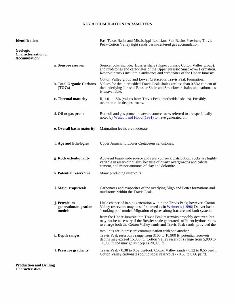
KEY ACCUMULATION PARAMETERS
Identification East Texas Basin and Mississippi-Louisiana Salt Basins Province; Travis Peak-Cotton Valley tight sands basin-centered gas accumulation
Geologic Characterization of Accumulation:
a. Source/reservoir Source rocks include: Bossier shale (Upper Jurassic Cotton Valley group), and mudstones and carbonates of the Upper Jurassic Smackover Formation. Reservoir rocks include: Sandstones and carbonates of the Upper Jurassic
Cotton Valley group and Lower Cretaceous Travis Peak Formation.b. Total Organic Carbons
(TOCs)Values for the interbedded Travis Peak shales are less than 0.5%; content of the underlying Jurassic Bossier Shale and Smackover shales and carbonates is unavailable.
c. Thermal maturity Ro 1.0 – 1.8% (values from Travis Peak interbedded shales). Possibly overmature in deepest rocks.
d. Oil or gas prone Both oil and gas prone; however, source rocks referred to are specifically noted by Wescott and Hood (1991) to have generated oil.
e. Overall basin maturity Maturation levels are moderate.
f. Age and lithologies Upper Jurassic to Lower Cretaceous sandstones.
g. Rock extent/quality Apparent basin-wide source and reservoir rock distribution; rocks are highly variable in reservoir quality because of quartz overgrowths and calcite cement, and minor amounts of clay and dolomite.
h. Potential reservoirs Many producing reservoirs.
i. Major traps/seals Carbonates and evaporites of the overlying Sligo and Pettet formations and mudstones within the Travis Peak.
j. Petroleum generation/migration models
Little chance of in-situ generation within the Travis Peak; however, Cotton Valley reservoirs may be self-sourced as in Weimer’s (1996) Denver basin "cooking pot" model. Migration of gases along fracture and fault systems
from the Upper Jurassic into Travis Peak reservoirs probably occurred, but may not be necessary if the Bossier shale generated sufficient hydrocarbons to charge both the Cotton Valley sands and Travis Peak sands, provided the
two units are in pressure communication with one another.k. Depth ranges Travis Peak reservoirs range from 3100 to 10,900 ft; potential reservoir
depths may exceed 15,000 ft. Cotton Valley reservoirs range from 5,000 to 11,000 ft and may go as deep as 20,000 ft.
l. Pressure gradients Travis Peak - 0.38 to 0.52 psi/foot; Cotton Valley sands - 0.32 to 0.55 psi/ft; Cotton Valley carbonate (oolitic shoal reservoirs) - 0.50 to 0.66 psi/ft.
Production and Drilling Characteristics:

a. Important fields/reservoirs
Bethany (Travis Peak), Carthage (Travis Peak, Cotton Valley), Waskom (Travis Peak, Cotton Valley), Trawick (Travis Peak), Opelinka (Travis Peak, Rosewood (Cotton Valley), Henderson North (Travis Peak, Cotton Valley),
Blocker (Cotton Valley).b. Cumulative production Travis Peak - 508.3 BCFG (1970-1988); Cotton Valley - 2,665.5 BCFG
(1970-1988).
Economic Characteristics:
a. Inert gas content
b. Recovery Recoveries vary depending on permeability (degree of cementation and fracturing), and porosity.
c. Pipeline infrastructure very good.
d. Exploration maturity relative to other basins
e. Sediment consolidation Most rocks are well indurated.
f. Porosity/completion problems
Iron oxide precipitates common in some Cotton Valley sandstone reservoirs, calcite and silica cementation restrict porosity, minor clay problems.
g. Permeability Travis Peak - 0.0004 to 0.8 md; Cotton Valley - 0.015 to 0.043 md.
h. Porosity Travis Peak - 5-17%; Cotton Valley - 6 to 11%.
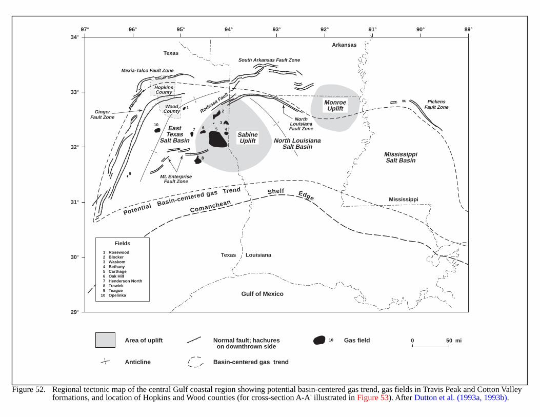
97°34°
33°
32°
31°
30°
29°
96° 95° 94° 93° 92° 91° 90° 89°
Texas
Texas
Louisiana
Mississippi
Arkansas
Comanchean
Shelf Edge
Potential Basin-centered gas Trend
SabineUplift
MonroeUplift
EastTexas
Salt Basin
MississippiSalt Basin
Gulf of Mexico
North LouisianaSalt Basin
WoodCounty
HopkinsCounty
Mexia-Talco Fault Zone
South Arkansas Fault Zone
Mt. EnterpriseFault Zone
NorthLouisianaFault Zone
GingerFault Zone
PickensFault Zone
Rodessa Fault
12
3
456710
8
9
123456789
10
RosewoodBlockerWaskomBethanyCarthageOak HillHenderson NorthTrawickTeagueOpelinka
Fields
0 50 miArea of uplift Gas field
Anticline
Normal fault; hachures on downthrown side
Basin-centered gas trend
Figure 52. Regional tectonic map of the central Gulf coastal region showing potential basin-centered gas trend, gas fields in Travis Peak and Cotton Valleyformations, and location of Hopkins and Wood counties (for cross-section A-A' illustrated in Figure 53). After Dutton et al. (1993a, 1993b).
10
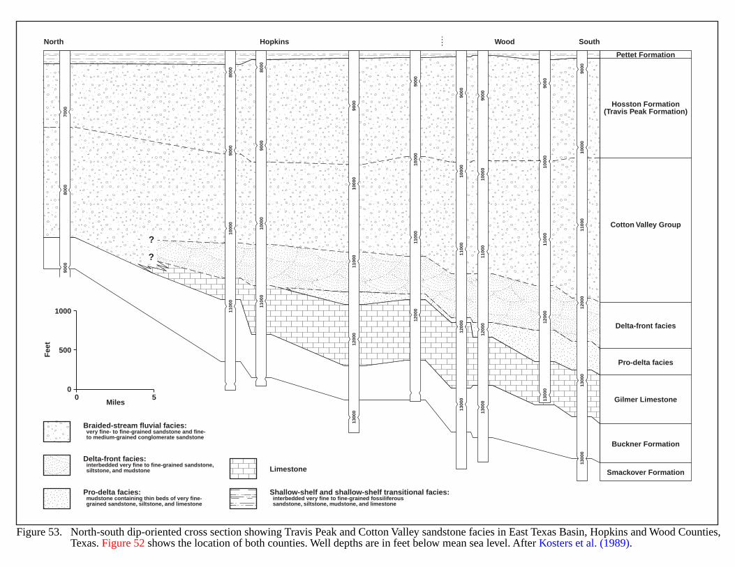
Pettet Formation
Hosston Formation(Travis Peak Formation)
Cotton Valley Group
Delta-front facies
Pro-delta facies
Gilmer Limestone
Buckner Formation
Smackover Formation
HopkinsNorth SouthWood
7000
8000
9000
8000
1000
0
8000
9000 90
00
1100
0
1100
010
000
1000
011
000
1200
013
000
9000
1000
090
0011
000
1200
0
1000
090
0011
000
1200
013
000
1000
0 1000
0
1000
0
9000
9000
9000
1100
0 1100
0
1100
0
1200
0 1200
0
1200
0
1300
0 1300
0
1300
013
000
?
?
00
500
1000
5Miles
Fee
t
Braided-stream fluvial facies: very fine- to fine-grained sandstone and fine- to medium-grained conglomerate sandstone
Delta-front facies: interbedded very fine to fine-grained sandstone, siltstone, and mudstone Limestone
Pro-delta facies: mudstone containing thin beds of very fine- grained sandstone, siltstone, and limestone
Shallow-shelf and shallow-shelf transitional facies: interbedded very fine to fine-grained fossiliferous sandstone, siltstone, mudstone, and limestone
Figure 53. North-south dip-oriented cross section showing Travis Peak and Cotton Valley sandstone facies in East Texas Basin, Hopkins and Wood Counties,Texas. Figure 52 shows the location of both counties. Well depths are in feet below mean sea level. After Kosters et al. (1989).
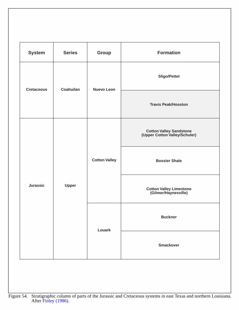
System
Cretaceous
Jurassic Upper
Coahuilan Nuevo Leon
Sligo/Pettet
Travis Peak/Hosston
Cotton Valley Sandstone(Upper Cotton Valley/Schuler)
Bossier Shale
Cotton Valley Limestone(Gilmer/Haynesville)
Buckner
Smackover
Cotton Valley
Louark
Series Group Formation
Figure 54. Stratigraphic column of parts of the Jurassic and Cretaceous systems in east Texas and northern Louisiana.After Finley (1986).
125
HANNA BASIN
GEOLOGIC SETTING
The Hanna Basin is an intermontane basin in the Rocky Mountain foreland province in southeast Wyoming(Figure 55). The basin covers about 1,000 square miles and contains almost 38,000 ft of Cretaceous and Tertiarysediments (Figure 56). At least 18,000 ft of Late Cretaceous and early Tertiary sediments were deposited within 15million years, creating thermally mature hydrocarbon source rocks in the basin center (Bierei and Surdham, 1986;Bierei, 1987). The Upper Cretaceous Medicine Bow, Lewis and Mesaverde Formations consist of up to 15,000 ft ofdark marine organic-rich shales (Figure 57). The Eocene-Paleocene Hanna and Ferris Formations include almost14,000 ft of organically rich lacustrine shales, coals and fluviatile sandstones (Perry, 1992; Bierei, 1987; Matson,1984a, b). This excessive sedimentation resulted from abrupt basin subsidence associated with Laramide tectonism(Lillegraven, 1995; Bierei and Surdham, 1986; Shelton, 1968). The basin is asymmetric and is surrounded bynumerous Laramide thrust faults (Figures 55 and 56).
The high subsidence rates that occurred in the Hanna basin are typical of wrench basins with strike-slip faulting(Perry, 1992).
HYDROCARBON PRODUCTION
The Hanna basin has several fields that produce both oil and gas (Kaplan and Skeen, 1985; Matson, 1984a, b;Porter, 1979b; McCaslin, 1978). To date, natural gas has been found only in sandstone reservoirs (Mitchell, 1968).The nonmarine rocks are currently being explored for coal and coal gas (Perry, 1992). There is no current productionof coal gas in the basin.
EVIDENCE FOR BASIN-CENTERED GAS
Sparse exploratory drilling and lack of data make forecasts difficult. The Hanna basin has similar rock sequencesto the Greater Green River basin, where Law and others (1984; 1989) have described basin-center gas systems.Pontolillo and Stanton (1994) measured vitrinite reflectance values greater than 1% below 11,000 ft in the Champlinand Brinkerhoff wells; these values exceed the 0.8% threshold that generally indicates the top of abnormal pressuresand possible thermogenic gas generation (Johnson and Finn, 1998; Law, 1984) (Figure 58).
Late Cretaceous marine rocks in the basin show total organic carbon (TOC) values greater than 0.5%. TheHanna, Ferris, Medicine Bow, and Mesaverde Formations have coal beds and carbonaceous shales with variable TOCvalues (0.5 to 35.6 wt% avg, 3.2 wt% TOC). Marine sediments of the Lewis, Steele, Niobrara, and FrontierFormations have TOC range of 0.4 to 4.3 and average of 1.5 wt% TOC (Bierei, 1987).
Most of the known traps are structural closures around the edges of the basin (Matson, 1984a, b). Severalstructural/stratigraphic traps are also present (Porter, 1979a; McCaslin, 1978). Stratigraphic traps may occur in thedeeper part of the basin, in low permeability and possibly overpressured Eocene, Paleocene and Upper Cretaceousrocks (Matson, 1984a, b). Major seals include the black/dark shales of the Cretaceous Mowry, Steele, Thermopolis,and Mesaverde Formations, and Paleocene and Eocene rocks.
Time-temperature calculations locate the oil generation window at 7,200 to 11,480 ft depth in the basin center.Apparently, hydrocarbon generation began about 80 Ma at the base of the Late Cretaceous section in the Hannabasin. Transformation models show that source rocks generated and expelled hydrocarbons very quickly. At present,the Hanna basin is not generating any significant amounts of hydrocarbons.
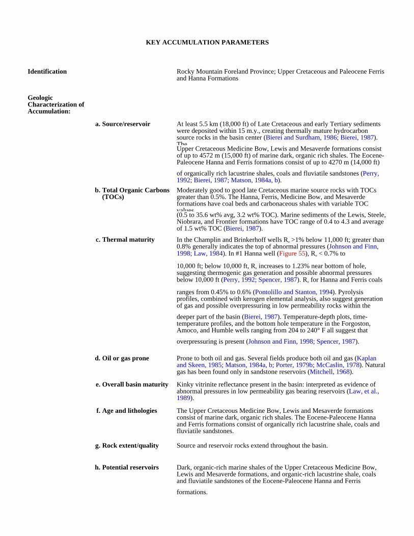
KEY ACCUMULATION PARAMETERS
Identification Rocky Mountain Foreland Province; Upper Cretaceous and Paleocene Ferris and Hanna Formations
Geologic Characterization of Accumulation:
a. Source/reservoir At least 5.5 km (18,000 ft) of Late Cretaceous and early Tertiary sediments were deposited within 15 m.y., creating thermally mature hydrocarbon source rocks in the basin center (Bierei and Surdham, 1986; Bierei, 1987). The Upper Cretaceous Medicine Bow, Lewis and Mesaverde formations consist of up to 4572 m (15,000 ft) of marine dark, organic rich shales. The Eocene-Paleocene Hanna and Ferris formations consist of up to 4270 m (14,000 ft)
of organically rich lacustrine shales, coals and fluviatile sandstones (Perry, 1992; Bierei, 1987; Matson, 1984a, b).
b. Total Organic Carbons (TOCs)
Moderately good to good late Cretaceous marine source rocks with TOCs greater than 0.5%. The Hanna, Ferris, Medicine Bow, and Mesaverde formations have coal beds and carbonaceous shales with variable TOC values(0.5 to 35.6 wt% avg, 3.2 wt% TOC). Marine sediments of the Lewis, Steele, Niobrara, and Frontier formations have TOC range of 0.4 to 4.3 and average of 1.5 wt% TOC (Bierei, 1987).
c. Thermal maturity In the Champlin and Brinkerhoff wells Ro >1% below 11,000 ft; greater than 0.8% generally indicates the top of abnormal pressures (Johnson and Finn, 1998; Law, 1984). In #1 Hanna well (Figure 55), Ro < 0.7% to
10,000 ft; below 10,000 ft, Ro increases to 1.23% near bottom of hole, suggesting thermogenic gas generation and possible abnormal pressures below 10,000 ft (Perry, 1992; Spencer, 1987). Ro for Hanna and Ferris coals
ranges from 0.45% to 0.6% (Pontolillo and Stanton, 1994). Pyrolysis profiles, combined with kerogen elemental analysis, also suggest generation of gas and possible overpressuring in low permeability rocks within the
deeper part of the basin (Bierei, 1987). Temperature-depth plots, time-temperature profiles, and the bottom hole temperature in the Forgoston, Amoco, and Humble wells ranging from 204 to 240° F all suggest that
overpressuring is present (Johnson and Finn, 1998; Spencer, 1987).
d. Oil or gas prone Prone to both oil and gas. Several fields produce both oil and gas (Kaplan and Skeen, 1985; Matson, 1984a, b; Porter, 1979b; McCaslin, 1978). Natural gas has been found only in sandstone reservoirs (Mitchell, 1968).
e. Overall basin maturity Kinky vitrinite reflectance present in the basin: interpreted as evidence of abnormal pressures in low permeability gas bearing reservoirs (Law, et al., 1989).
f. Age and lithologies The Upper Cretaceous Medicine Bow, Lewis and Mesaverde formations consist of marine dark, organic rich shales. The Eocene-Paleocene Hanna and Ferris formations consist of organically rich lacustrine shale, coals and fluviatile sandstones.
g. Rock extent/quality Source and reservoir rocks extend throughout the basin.
h. Potential reservoirs Dark, organic-rich marine shales of the Upper Cretaceous Medicine Bow, Lewis and Mesaverde formations, and organic-rich lacustrine shale, coals and fluviatile sandstones of the Eocene-Paleocene Hanna and Ferris
formations.
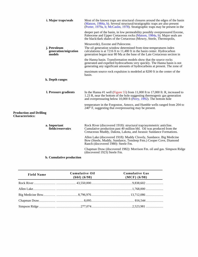
i. Major traps/seals Most of the known traps are structural closures around the edges of the basin (Matson, 1984a, b). Several structural/stratigraphic traps are also present (Porter, 1979a, b; McCaslin, 1978). Stratigraphic traps may be present in the
deeper part of the basin, in low permeability possibly overpressured Eocene, Paleocene and Upper Cretaceous rocks (Matson, 1984a, b). Major seals are the black/dark shales of the Cretaceous (Mowry, Steele, Thermopolis,
Mesaverde), Eocene and Paleocene.j. Petroleum
generation/migration models
The oil generation window determined from time-temperatures index calculations is at 7216 ft to 11,480 ft in the basin center. Hydrocarbon generation began near 80 Ma at the base of the Late Cretaceous section in
the Hanna basin. Transformation models show that the source rocks generated and expelled hydrocarbons very quickly. The Hanna basin is not generating any significant amounts of hydrocarbons at present. The zone of
maximum source rock expulsion is modeled at 8200 ft in the center of the basin.
k. Depth ranges
l. Pressure gradients In the Hanna #1 well (Figure 55) from 11,000 ft to 17,000 ft: Ro increased to 1.23 Ro near the bottom of the hole suggesting thermogenic gas generation and overpressuring below 10,000 ft (Perry, 1992). The bottom hole
temperature in the Forgoston, Amoco, and Humble wells ranged from 204 to 240° F, suggesting that overpressuring may be present.
Production and Drilling Characteristics:
a. Important fields/reservoirs
Rock River (discovered 1918): structural trap/asymmetric anticline. Cumulative production past 40 million bbl. Oil was produced from the Cretaceous Muddy, Dakota, Lakota, and Jurassic Sundance Formations.
Allen Lake (discovered 1918): Muddy Clovely, Sundance. Big Medicine Bow (Steele, Muddy, Sundance, Tensleep Fms.) Cooper Cove, Diamond Ranch (discovered 1980): Steele Fm.
Chapman Draw (discovered 1982): Morrison Fm. oil and gas. Simpson Ridge (discovered 1923) Steele Fm.
b. Cumulative production
Field Name Cumulative Oil(bbl) (6/98)
Cumulative Gas(MCF) (6/98)
Rock River ...................... .................... 43,550,000..........................................9,838,602 ..................
Allen Lake....................... ..............................................................................1,768,000 ..................
Big Medicine Bow............. ...................... 8,796,976........................................ 13,712,086 ..................
Chapman Draw................. ............................ 8,095............................................ 816,544 ..................
Simpson Ridge ................. .........................277,074..........................................2,523,981 ..................

Economic Characteristics:
a. Inert gas content
b. Recovery
c. Pipeline infrastructure Major gas pipelines run west and south of the Hanna basin to transport gas from the Greater Green River basin and other gas fields in the Rocky Mountain Region.
d. Exploration maturity relative to other basins
Mature
e. Sediment consolidation
f. Porosity/completion problems
g. Permeability
h. Porosity
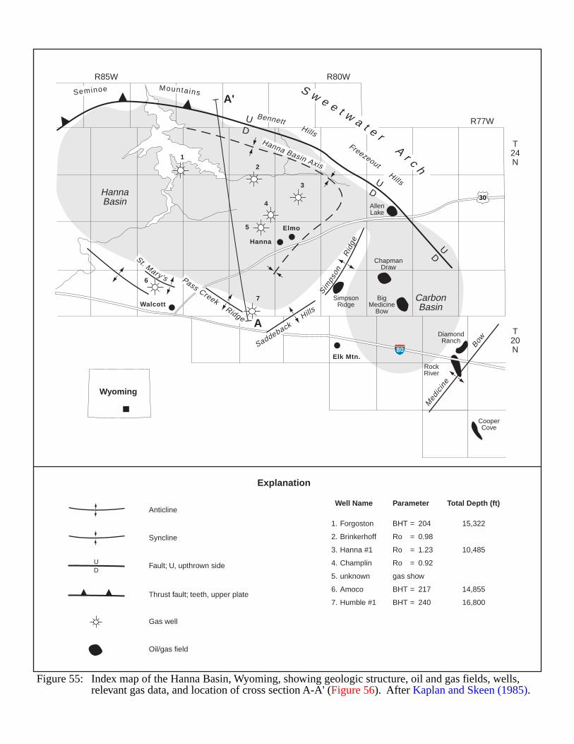
CarbonBasin
HannaBasin
SimpsonRidge
BigMedicine
Bow
RockRiver
CooperCove
DiamondRanch
ChapmanDraw
AllenLake
Wyoming
R85W R80W
R77W
T20N
T24N
Elk Mtn.
Elmo
Hanna
Walcott
Seminoe Mountains
BennettHills
FreezeoutHills
S w e e t w a t e rA
r c h
30
80
UD
UD
UD
Simps
onR
idge
SaddebackHills
Pass CreekRidge
St. Mary's
Med
icine
B
ow
Hanna Basin Axis1
2
3
4
5
6
7
A'
A
1. Forgoston
2. Brinkerhoff
3. Hanna #1
4. Champlin
5. unknown
6. Amoco
7. Humble #1
BHT = 204
Ro = 0.98
Ro = 1.23
Ro = 0.92
gas show
BHT = 217
BHT = 240
Anticline
Syncline
Thrust fault; teeth, upper plate
UD
Fault; U, upthrown side
15,322
10,485
14,855
16,800
Well Name Parameter Total Depth (ft)
Gas well
Oil/gas field
Explanation
Figure 55: Index map of the Hanna Basin, Wyoming, showing geologic structure, oil and gas fields, wells, relevant gas data, and location of cross section A-A' (Figure 56). After Kaplan and Skeen (1985).
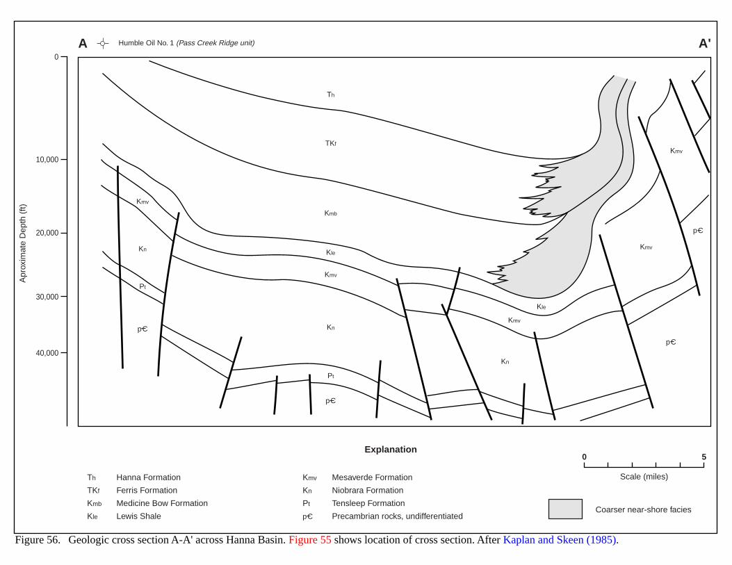
Th
TKf
Kmb
Kle
Kle
Kmv
Kmv
Kmv
Kmv
Kmv
Kn
Kn
Kn
Pt
Pt
pC
pC
pC
pC
0
10,000
20,000
30,000
40,000
Apr
oxim
ate
Dep
th (
ft)
Explanation
Th
TKf
Kmb
Kle
Hanna Formation
Ferris Formation
Medicine Bow Formation
Lewis Shale
Mesaverde Formation
Niobrara Formation
Tensleep Formation
Precambrian rocks, undifferentiatedCoarser near-shore facies
Kmv
Kn
Pt
pC
Humble Oil No. 1 (Pass Creek Ridge unit)
0
Scale (miles)
5
Figure 56. Geologic cross section A-A' across Hanna Basin. Figure 55 shows location of cross section. After Kaplan and Skeen (1985).
A'A
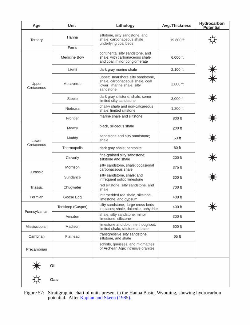
Age Unit Lithology Avg. Thickness HydrocarbonPotential
TertiaryHanna siltstone, silty sandstone, and
shale; carbonaceous shale underlying coal beds
19,800 ft
6,000 ft
2,100 ft
2,600 ft
3,000 ft
1,200 ft
800 ft
200 ft
63 ft
80 ft
200 ft
375 ft
300 ft
700 ft
400 ft
400 ft
300 ft
500 ft
65 ft
continental silty sandstone, and shale; with carbonaceous shale and coal; minor conglomerate
dark gray marine shale
upper: nearshore silty sandstone,shale, carbonaceous shale, coallower: marine shale, silty sandstone
dark gray siltstone, shale; somelimited silty sandstone
chalky shale and non-calcareousshale; limited siltstone
marine shale and siltstone
black, siliceous shale
sandstone and silty sandstone; shale
dark gray shale; bentonite
fine-grained silty sandstone; siltstone and shale
silty sandstone, shale; occasionalcarbonaceous shale
silty sandstone, shale; andinfrequent oolitic limestone
red siltstone, silty sandstone, andshale
interbedded red shale, siltstone,limestone, and gypsum
silty sandstone; large cross-bedsin places; shale, dolomite, anhydrite
shale, silty sandstone, minorlimestone, siltstone
limestone and dolomite thoughout;limited shale; siltstone at base
transgressive silty sandstone,siltstone, and shale
schists, gneisses, and migmatitesof Archean Age; intrusive granites
Ferris
Medicine Bow
Lewis
Mesaverde
Steele
Niobrara
Frontier
Mowry
Muddy
Thermopolis
Cloverly
Morrison
Sundance
Chugwater
Goose Egg
Tensleep (Casper)
Amsden
Madison
Flathead
UpperCretaceous
LowerCretaceous
Jurassic
Triassic
Permian
Pennsylvanian
Mississippian
Cambrian
Precambrian
Figure 57: Stratigraphic chart of units present in the Hanna Basin, Wyoming, showing hydrocarbonpotential. After Kaplan and Skeen (1985).
Oil
Gas
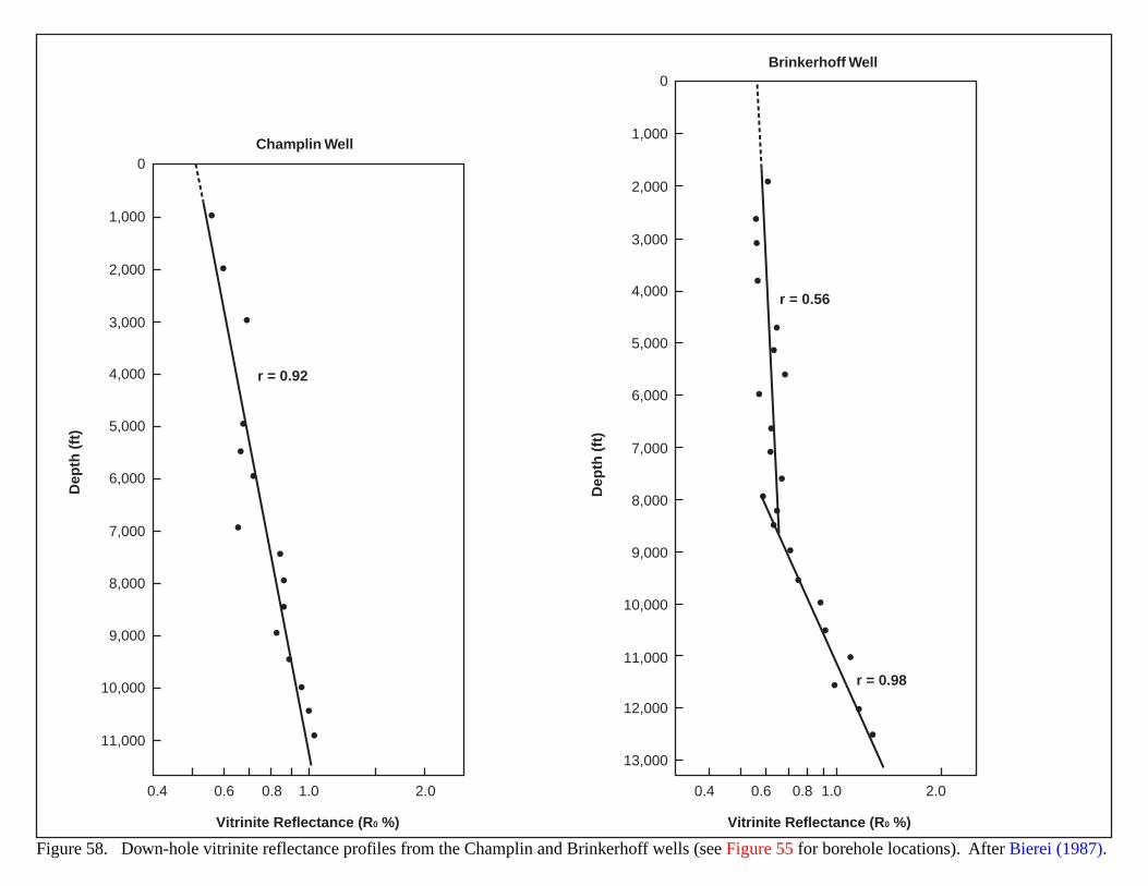
0.4 0.6 0.8 1.0 2.0
0
1,000
2,000
3,000
4,000
5,000
6,000
7,000
8,000
9,000
10,000
11,000
Dep
th (
ft)
Champlin Well
Vitrinite Reflectance (R0 %)
r = 0.92
0.4 0.6 0.8 1.0 2.0
0
1,000
2,000
3,000
4,000
5,000
6,000
7,000
8,000
9,000
10,000
11,000
12,000
13,000
Dep
th (
ft)
r = 0.56
Brinkerhoff Well
Vitrinite Reflectance (R0 %)
r = 0.98
Figure 58. Down-hole vitrinite reflectance profiles from the Champlin and Brinkerhoff wells (see Figure 55 for borehole locations). After Bierei (1987).
133
HORNBROOK BASIN/MODOC PLATEAU
GEOLOGIC SETTING
The Hornbrook Basin is located in the northeast corner of California and south-central Oregon, and is boundedon the west by the Klamath Mountains (Figure 59). The Cascade Mountains and the central Oregon volcanicplateaus form the basin’s northern boundary. The basin becomes progressively more block-faulted eastward,eventually converging with the Basin and Range. The southern boundary stretches across part of the Basin andRange, the northern end of the Sierra Nevada, the Sacramento Valley, and the Klamath Mountains. The Cascadesoverlap part of the basin, dividing the Shasta Valley on the west from the Modoc Plateau to the east.
Potential source and reservoir strata in the basin include the Upper Cretaceous Hornbrook Formation and theoverlying Upper Cretaceous-Eocene Montgomery Creek Formation (Figures 60 and 61). Deposition of theHornbrook occurred in a large, relatively undeformed basin called the “Hornbrook Basin.” This basin probablyextended beyond the present limits, and probably connected with the Sacramento/Great Valley basins to the south andto the Ochoco Basin northeast in central Oregon. Some Hornbrook strata may have continuity with the Great ValleySequence. The Hornbrook Formation derives mostly from debris shed from the Klamath Mountains and restsunconformably on pre-Cretaceous metamorphic and igneous basement (Figure 61). The basal unit is a marine tomarginal-marine conglomerate. The formation includes several fining-upwards marine sequences, and the uppermostunit is a 2,600 ft-thick marine shale. At the type section, the Hornbrook has a thickness of 4,200 ft (Nilsen, 1984b).
The Montgomery Creek Formation also contains much organic shale and siltstone, although deposition occurredmostly in a braided stream, non-marine environment (Higinbotham, 1986).
Erskine et al. (1984) measured the integrated potential of the basin and deduced that non-magnetic strata(principally Hornbrook and lower Montgomery Creek rocks) thicken eastward under the Cascade Range volcanics andthe basalts of the Modoc Plateau (Figure 60). They projected a thickness of 16,000 ft for this sequence ofsedimentary strata. Erskine’s findings suggest the Hornbrook basin formed by uplift of the Klamaths during theNevadan orogeny, and that it may be as relatively undeformed beneath the Modoc basalts as is the Upper CretaceousGreat Valley Sequence to the south. The basin continued to fill without significant tectonic interruption until theonset of Basin and Range deformation in the middle Miocene. Thereafter, horst-and-graben structures developed in theeastern Modoc Plateau. Thick plateau basalts covered the basin in the middle Miocene and early Pliocene. Cascadevolcanism affected the west-central part of the original basin from the late Pliocene to the present.
HYDROCARBON PRODUCTION
Most oil, water and geothermal wells drilled to a depth of 500 ft or greater generally have had gas shows. Oneoperator drilled three wells to 1,200 ft near the north end of Honey Lake and found flow rates of 200 to 450 MCFD,probably originating from a Pliocene lacustrine sand. The wells never produced commercially. Montgomery (1988a)noted that the Klamath 1 Kuck well in northeastern Siskiyou County had oil shows from two Upper Cretaceoussands, but ultimately produced only salt water (Figure 59).
134
EVIDENCE FOR BASIN-CENTERED GAS
Several lines of evidence possibly indicate basin-centered gas in the Hornbrook Basin:
1) gas seeps and a non-commercial gas field;
2) source rocks capable of generating gas; and
3) a possible 16,000-ft thick section of “non-magnetic sedimentary rock.”
Total organic carbon (TOC) values for the Hornbrook Formation range from 0.1 to 1.2 wt%, and average 0.52wt% (Figure 62) (Law et al., 1984). Figure 62 shows that vitrinite reflectance of samples taken along the Interstate 5corridor ranges from 0.40 to 0.83.
Potential source rocks include coal and coal-bearing shales within the Blue Gulch Mudstone and Dutch CreekSiltstone members of the Hornbrook Formation (Keighin and Law, 1984), and coal-bearing flood-plain and marshmudstones and lacustrine deposits of the upper Cretaceous to Eocene Montgomery Creek Formation (Higinbotham,1986). Some of these sediments crop out in the Shasta Valley and in other parts of the western basin. The units dipgenerally eastward to a depth of 15,000 ft in the central Modoc Plateau. Thus, most of the source rocks probably lieat depths from 15,000 to 31,000 ft in much of the basin. At these depths the most likely hydrocarbons would bethermally generated natural gas. Law et al. (1984) noted the kerogen is Type III and would probably produce gas andlittle or no oil.
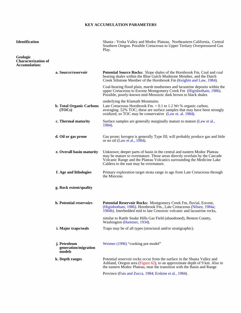
KEY ACCUMULATION PARAMETERS
Identification Shasta - Yreka Valley and Modoc Plateau, Northeastern California, Central Southern Oregon. Possible Cretaceous to Upper Tertiary Overpressured Gas Play.
Geologic Characterization of Accumulation:
a. Source/reservoir Potential Source Rocks: Slope shales of the Hornbrook Fm. Coal and coal bearing shales within the Blue Gulch Mudstone Member, and the Dutch Creek Siltstone Member of the Hornbrook Fm (Keighin and Law, 1984).
Coal-bearing flood plain, marsh mudstones and lacustrine deposits within the upper Cretaceous to Eocene Montgomery Creek Fm (Higinbotham, 1986). Possible, poorly-known mid-Mesozoic dark brown to black shales
underlying the Klamath Mountains.b. Total Organic Carbons
(TOCs)Late Cretaceous Hornbrook Fm. = 0.1 to 1.2 Wt % organic carbon, averaging .52% TOC; these are surface samples that may have been strongly oxidized, so TOC may be conservative (Law et. al. 1984).
c. Thermal maturity Surface samples are generally marginally mature to mature (Law et al., 1984).
d. Oil or gas prone Gas prone; kerogen is generally Type III; will probably produce gas and little or no oil (Law et al., 1984).
e. Overall basin maturity Unknown; deeper parts of basin in the central and eastern Modoc Plateau may be mature to overmature. Those areas directly overlain by the Cascade Volcanic Range and the Plateau Volcanics surrounding the Medicine Lake Caldera to the east may be overmature.
f. Age and lithologies Primary exploration target strata range in age from Late Cretaceous through the Miocene.
g. Rock extent/quality
h. Potential reservoirs Potential Reservoir Rocks: Montgomery Creek Fm, fluvial, Eocene, (Higinbotham, 1986). Hornbrook Fm., Late Cretaceous (Nilsen, 1984a; 1984b). Interbedded mid to late Cenozoic volcanic and lacustrine rocks,
similar to Rattle Snake Hills Gas Field (abandoned), Benton County, Washington (Hammer, 1934).
i. Major traps/seals Traps may be of all types (structural and/or stratigraphic).
j. Petroleum generation/migration models
Weimer (1996) “cooking pot model”
k. Depth ranges Potential reservoir rocks occur from the surface in the Shasta Valley and Ashland, Oregon area (Figure 62), to an approximate depth of 9 km. Also in the eastern Modoc Plateau, near the transition with the Basin and Range
Province (Fuis and Zucca, 1984; Erskine et al., 1984).
l. Pressure gradients
Production and Drilling Characteristics:
a. Important fields/reservoirs
none
b. Cumulative production none
Economic Characteristics:
a. Inert gas content Unknown though possible; other basins with a high volcanic and intrusive content often contain higher than normal CO2, helium, and other inert components.
b. Recovery
c. Pipeline infrastructure P G & E has a 36-in gas transmission line through the area. Additional lines are being built or are planned through the area to transport Canadian gas to the major central and southern California markets.
d. Exploration maturity relative to other basins
Immature, a frontier basin.
e. Sediment consolidation Target formations are very competent.
f. Porosity/completion problems
Hornbrook Fm permeability measured from surface samples is low, generally less than 1.2 md. However, this is an active tectonic area, and may have well-developed fracture porosity (Keighin and Law, 1984).
g. Permeability
h. Porosity
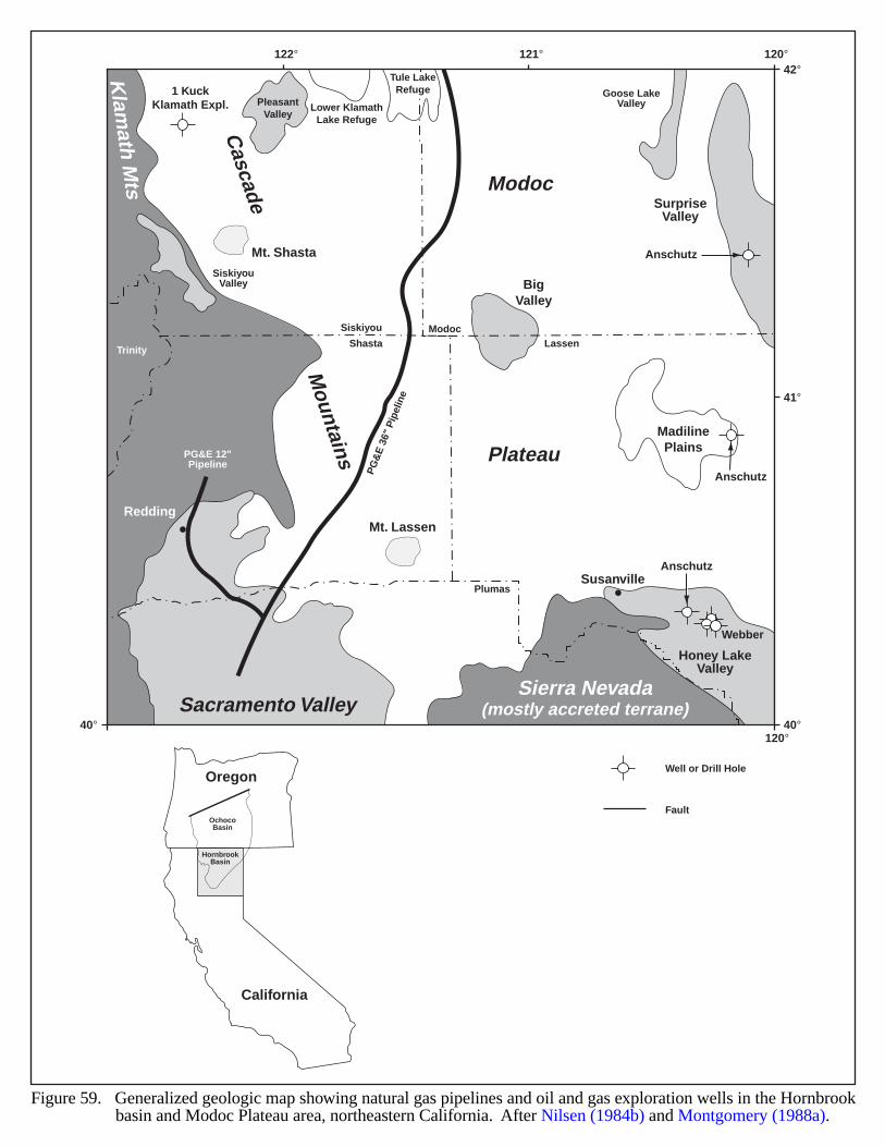
BigValley
PleasantValley
Lower KlamathLake Refuge
MadilinePlains
SurpriseValley
SiskiyouValley
Goose LakeValley
Honey LakeValley
Mt. Shasta
Mt. Lassen
Modoc
Plateau
Sacramento ValleySierra Nevada
(mostly accreted terrane)
Cascade M
ountains
Klam
ath Mts
ModocSiskiyou
TrinityShasta Lassen
Plumas
Redding
Susanville
PG
&E
36"
Pip
elin
e
PG&E 12"Pipeline
Tule LakeRefuge1 Kuck
Klamath Expl.
Anschutz
Anschutz
Anschutz
Webber
40°
41°
42°
40°120°
120°121°122°
Figure 59. Generalized geologic map showing natural gas pipelines and oil and gas exploration wells in the Hornbrookbasin and Modoc Plateau area, northeastern California. After Nilsen (1984b) and Montgomery (1988a).
Well or Drill Hole
Fault
California
Oregon
OchocoBasin
HornbrookBasin
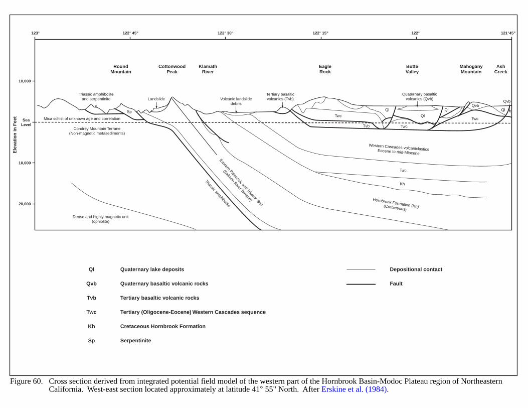
RoundMountain
CottonwoodPeak
KlamathRiver
EagleRock
ButteValley
MahoganyMountain
AshCreek
Mica schist of unknown age and correlation
Condrey Mountain Terrane(Non-magnetic metasediments)
Dense and highly magnetic unit(ophiolite)
Eastern Paleozoic and Triassic Belt
(Salmon River Terrane)
Triassic amphiboliteand serpentinite Volcanic landslide
debris
Tertiary basalticvolcanics (Tvb)
Quaternary basalticvolcanics (Qvb)
Ql
Ql
Ql
QvbQvb
Ql
Western Cascades volcaniclasticsEocene to mid-Miocene
Hornbrook Formation (Kh)(Cretaceous)
Kh
Twc
Twc
TwcTwc
Tvb
Landslide
20,000
10,000
SeaLevel
123° 122° 45" 122° 30" 122° 15" 122° 121°45"
10,000
Ele
vati
on
in F
eet
Triassic amphibolite
Depositional contact
Fault
Quaternary lake depositsQl
Qvb
Tvb
Twc
Kh
Quaternary basaltic volcanic rocks
Tertiary basaltic volcanic rocks
Tertiary (Oligocene-Eocene) Western Cascades sequence
Cretaceous Hornbrook Formation
Sp Serpentinite
Sp
Figure 60. Cross section derived from integrated potential field model of the western part of the Hornbrook Basin-Modoc Plateau region of NortheasternCalifornia. West-east section located approximately at latitude 41° 55" North. After Erskine et al. (1984).
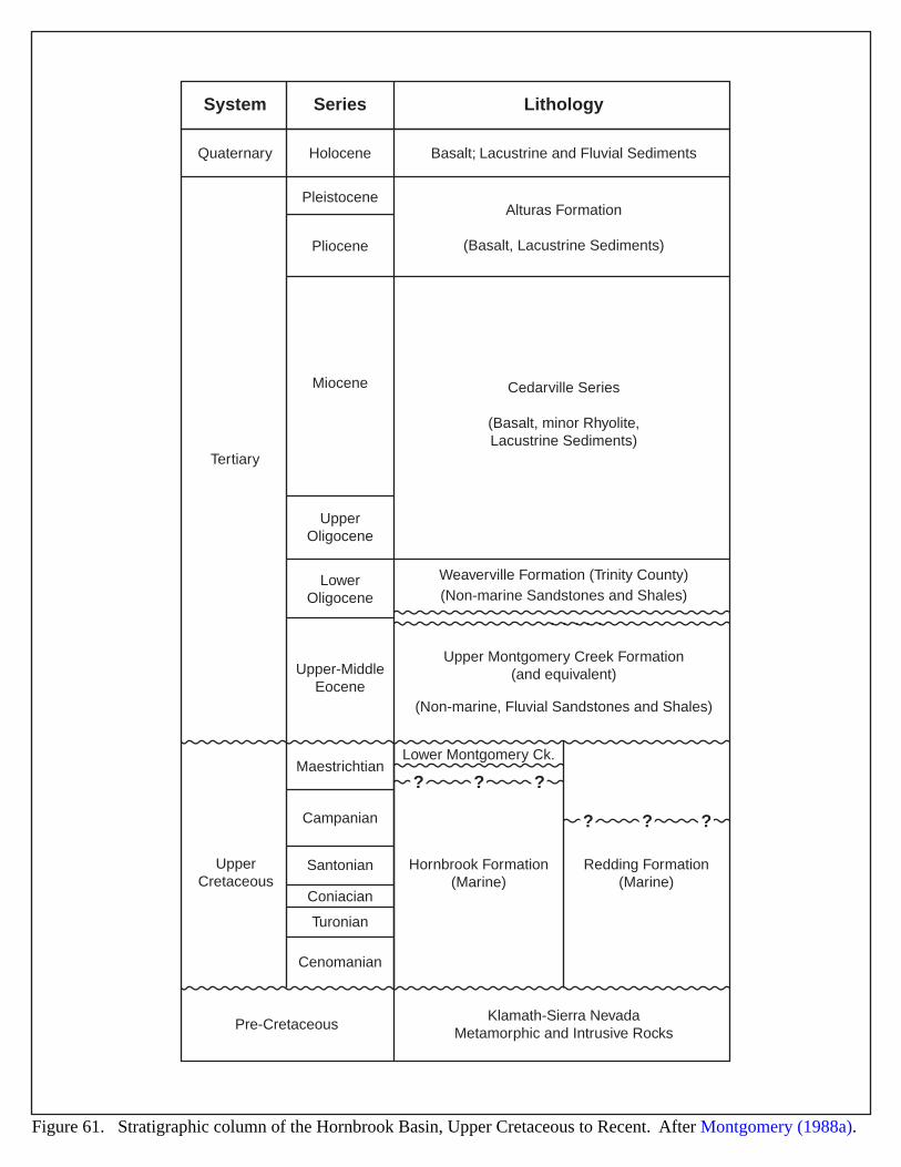
? ? ?
? ? ?
HoloceneQuaternary Basalt; Lacustrine and Fluvial Sediments
SeriesSystem Lithology
Cedarville Series
(Basalt, minor Rhyolite,Lacustrine Sediments)
Upper Montgomery Creek Formation(and equivalent)
(Non-marine, Fluvial Sandstones and Shales)
Klamath-Sierra NevadaMetamorphic and Intrusive Rocks
Alturas Formation
(Basalt, Lacustrine Sediments)
Weaverville Formation (Trinity County)(Non-marine Sandstones and Shales)
Pleistocene
Pliocene
Tertiary
UpperCretaceous
Miocene
UpperOligocene
LowerOligocene
Upper-MiddleEocene
Maestrichtian
Campanian
Santonian
Lower Montgomery Ck.
Hornbrook Formation(Marine)
Redding Formation(Marine)
Coniacian
Turonian
Cenomanian
Pre-Cretaceous
Figure 61. Stratigraphic column of the Hornbrook Basin, Upper Cretaceous to Recent. After Montgomery (1988a).
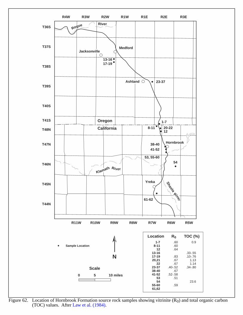
T36S
T37S
T38S
T39S
T40S
T41S
T48N
T47N
T46N
T45N
T44N
R11W R10W R9W R8W R7W R6W R5W
R4W R3W R2W R1W R1E R2E R3E
Jacksonville
Ashland
Yreka
Medford
Hornbrook
Klamath River
Shasta
River
Oregon
California
Rogue River
54
8-11
13-1617-19
20-22
23-37
12
1-7
41-52
53, 55-60
61-62
38-40
Location1-7
8-1112
13-1617-1920,21
2223-3738-4041-52
5354
55-6061,62
R0
.60
.60
.64
.83
.67
.67.40-.52
.67.52-.58
.51
.59
TOC (%)0.9
.33-.55
.10-.761.131.14
.34-.80
23.6
Figure 62. Location of Hornbrook Formation source rock samples showing vitrinite (R0) and total organic carbon(TOC) values. After Law et al. (1984).
0 5 10 miles
Scale
N
Sample Location
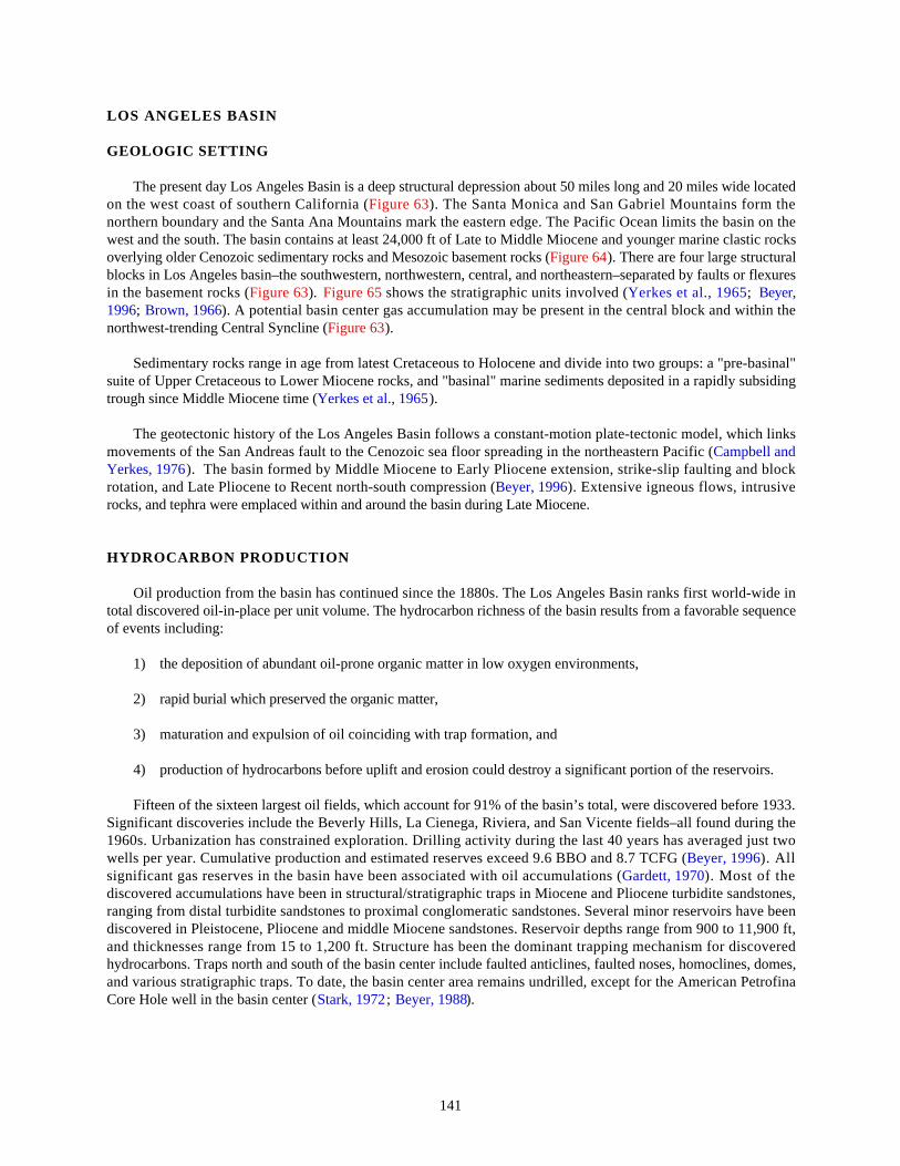
141
LOS ANGELES BASIN
GEOLOGIC SETTING
The present day Los Angeles Basin is a deep structural depression about 50 miles long and 20 miles wide locatedon the west coast of southern California (Figure 63). The Santa Monica and San Gabriel Mountains form thenorthern boundary and the Santa Ana Mountains mark the eastern edge. The Pacific Ocean limits the basin on thewest and the south. The basin contains at least 24,000 ft of Late to Middle Miocene and younger marine clastic rocksoverlying older Cenozoic sedimentary rocks and Mesozoic basement rocks (Figure 64). There are four large structuralblocks in Los Angeles basin–the southwestern, northwestern, central, and northeastern–separated by faults or flexuresin the basement rocks (Figure 63). Figure 65 shows the stratigraphic units involved (Yerkes et al., 1965; Beyer,1996; Brown, 1966). A potential basin center gas accumulation may be present in the central block and within thenorthwest-trending Central Syncline (Figure 63).
Sedimentary rocks range in age from latest Cretaceous to Holocene and divide into two groups: a "pre-basinal"suite of Upper Cretaceous to Lower Miocene rocks, and "basinal" marine sediments deposited in a rapidly subsidingtrough since Middle Miocene time (Yerkes et al., 1965).
The geotectonic history of the Los Angeles Basin follows a constant-motion plate-tectonic model, which linksmovements of the San Andreas fault to the Cenozoic sea floor spreading in the northeastern Pacific (Campbell andYerkes, 1976). The basin formed by Middle Miocene to Early Pliocene extension, strike-slip faulting and blockrotation, and Late Pliocene to Recent north-south compression (Beyer, 1996). Extensive igneous flows, intrusiverocks, and tephra were emplaced within and around the basin during Late Miocene.
HYDROCARBON PRODUCTION
Oil production from the basin has continued since the 1880s. The Los Angeles Basin ranks first world-wide intotal discovered oil-in-place per unit volume. The hydrocarbon richness of the basin results from a favorable sequenceof events including:
1) the deposition of abundant oil-prone organic matter in low oxygen environments,
2) rapid burial which preserved the organic matter,
3) maturation and expulsion of oil coinciding with trap formation, and
4) production of hydrocarbons before uplift and erosion could destroy a significant portion of the reservoirs.
Fifteen of the sixteen largest oil fields, which account for 91% of the basin’s total, were discovered before 1933.Significant discoveries include the Beverly Hills, La Cienega, Riviera, and San Vicente fields–all found during the1960s. Urbanization has constrained exploration. Drilling activity during the last 40 years has averaged just twowells per year. Cumulative production and estimated reserves exceed 9.6 BBO and 8.7 TCFG (Beyer, 1996). Allsignificant gas reserves in the basin have been associated with oil accumulations (Gardett, 1970). Most of thediscovered accumulations have been in structural/stratigraphic traps in Miocene and Pliocene turbidite sandstones,ranging from distal turbidite sandstones to proximal conglomeratic sandstones. Several minor reservoirs have beendiscovered in Pleistocene, Pliocene and middle Miocene sandstones. Reservoir depths range from 900 to 11,900 ft,and thicknesses range from 15 to 1,200 ft. Structure has been the dominant trapping mechanism for discoveredhydrocarbons. Traps north and south of the basin center include faulted anticlines, faulted noses, homoclines, domes,and various stratigraphic traps. To date, the basin center area remains undrilled, except for the American PetrofinaCore Hole well in the basin center (Stark, 1972; Beyer, 1988).
142
EVIDENCE FOR BASIN-CENTERED GAS
The American Petrofina Core Hole well bottomed at a depth of 21,215 ft in Delmontian (Upper Miocene toMiddle Pliocene) rocks in the basin center syncline (Beyer, 1996). Unfortunately, the well did not reach the Mohnian(Upper Miocene) section, which may be the equivalent of the (late Middle Miocene) Modelo Formation’s organic-rich "nodule shale" found elsewhere in the basin (Bostick et al., 1978). Therefore, drilling has not yet confirmed thepresence of source and reservoir rocks in the basin center. Shallower wells on the east flank of the Newport-Inglewood zone penetrated interbedded sandstone and shale containing type II kerogen in the lower Mohnian section(Beyer, 1996); the Mohnian rocks may be fractured because of fluid overpressuring during maturation of kerogen inthe organic-rich shale. The play, if present, will be in the Lower Mohnian section. Favorable conditions for basincenter gas accumulations are present in the Los Angeles basin for the following reasons:
1) Thermally mature source rocks (Ro values > than 1.2% and TOC's of 1-9%) are present in the basin center(Beyer, 1996);
2) Abnormally high formation pressures were measured both in the American Petrofina Core Hole in the basincenter syncline, and in the Standard Oil of California well (0.72 psi/ft) located northeast of the basin center(Bostick et al., 1978; Beyer, 1988);
3) High reservoir temperatures ranging from 205 to 304° F were measured in the central basin syncline (8,900to 15,500 ft);
4) Hydrocarbons are present in the basin center–the American Petrofina Core Hole well yielded 43° API gravityoil, with a high gas-oil ratio at 21,215 ft depth (Beyer, 1996); and
5) A thick section of Upper Miocene (Mohnian) rocks ranging in thickness from 3,000 to 7,000 ft may bepresent in the basin center (Beyer, 1996).
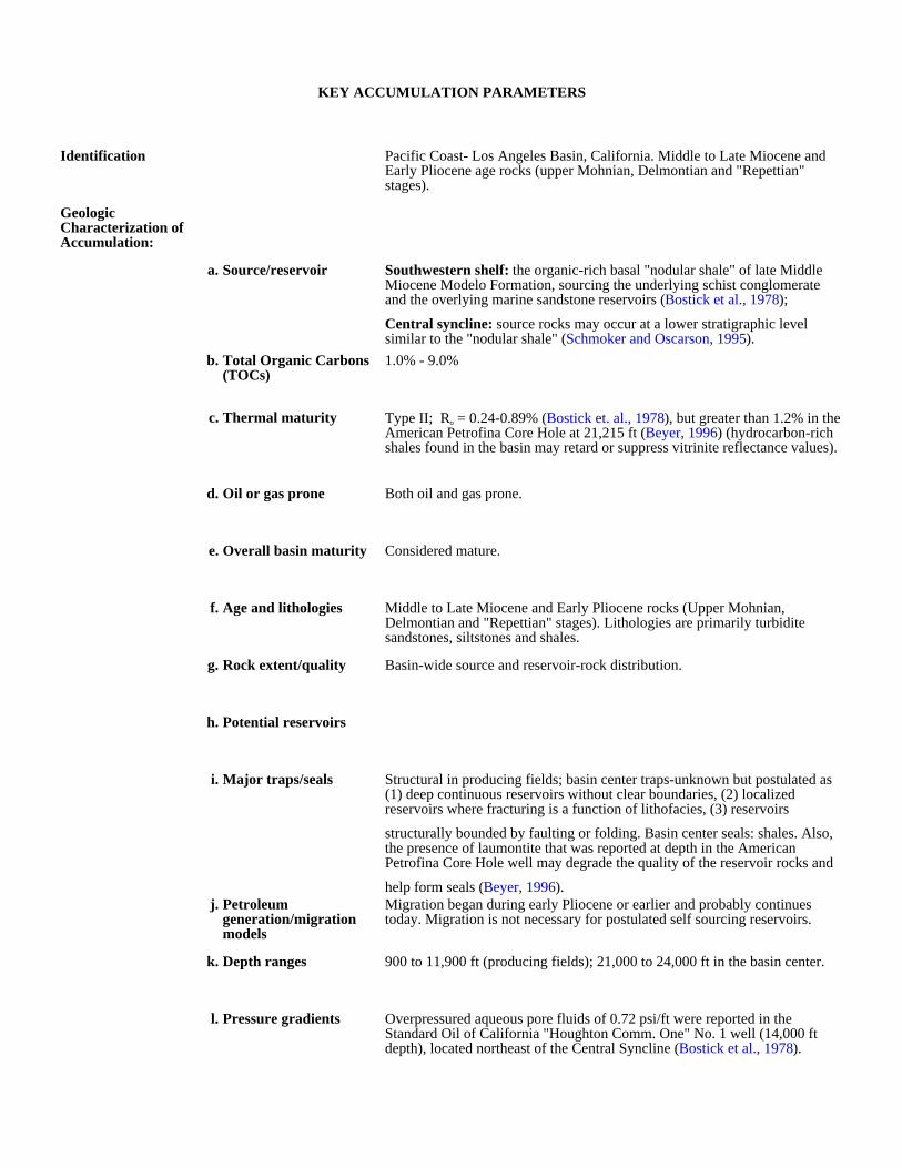
KEY ACCUMULATION PARAMETERS
Identification Pacific Coast- Los Angeles Basin, California. Middle to Late Miocene and Early Pliocene age rocks (upper Mohnian, Delmontian and "Repettian" stages).
Geologic Characterization of Accumulation:
a. Source/reservoir Southwestern shelf: the organic-rich basal "nodular shale" of late Middle Miocene Modelo Formation, sourcing the underlying schist conglomerate and the overlying marine sandstone reservoirs (Bostick et al., 1978);
Central syncline: source rocks may occur at a lower stratigraphic level similar to the "nodular shale" (Schmoker and Oscarson, 1995).
b. Total Organic Carbons (TOCs)
1.0% - 9.0%
c. Thermal maturity Type II; Ro = 0.24-0.89% (Bostick et. al., 1978), but greater than 1.2% in the American Petrofina Core Hole at 21,215 ft (Beyer, 1996) (hydrocarbon-rich shales found in the basin may retard or suppress vitrinite reflectance values).
d. Oil or gas prone Both oil and gas prone.
e. Overall basin maturity Considered mature.
f. Age and lithologies Middle to Late Miocene and Early Pliocene rocks (Upper Mohnian, Delmontian and "Repettian" stages). Lithologies are primarily turbidite sandstones, siltstones and shales.
g. Rock extent/quality Basin-wide source and reservoir-rock distribution.
h. Potential reservoirs
i. Major traps/seals Structural in producing fields; basin center traps-unknown but postulated as (1) deep continuous reservoirs without clear boundaries, (2) localized reservoirs where fracturing is a function of lithofacies, (3) reservoirs
structurally bounded by faulting or folding. Basin center seals: shales. Also, the presence of laumontite that was reported at depth in the American Petrofina Core Hole well may degrade the quality of the reservoir rocks and
help form seals (Beyer, 1996).j. Petroleum
generation/migration models
Migration began during early Pliocene or earlier and probably continues today. Migration is not necessary for postulated self sourcing reservoirs.
k. Depth ranges 900 to 11,900 ft (producing fields); 21,000 to 24,000 ft in the basin center.
l. Pressure gradients Overpressured aqueous pore fluids of 0.72 psi/ft were reported in the Standard Oil of California "Houghton Comm. One" No. 1 well (14,000 ft depth), located northeast of the Central Syncline (Bostick et al., 1978).
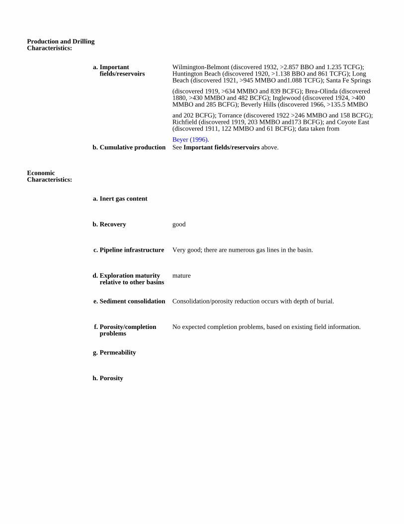
Production and Drilling Characteristics:
a. Important fields/reservoirs
Wilmington-Belmont (discovered 1932, >2.857 BBO and 1.235 TCFG); Huntington Beach (discovered 1920, >1.138 BBO and 861 TCFG); Long Beach (discovered 1921, >945 MMBO and1.088 TCFG); Santa Fe Springs
(discovered 1919, >634 MMBO and 839 BCFG); Brea-Olinda (discovered 1880, >430 MMBO and 482 BCFG); Inglewood (discovered 1924, >400 MMBO and 285 BCFG); Beverly Hills (discovered 1966, >135.5 MMBO
and 202 BCFG); Torrance (discovered 1922 >246 MMBO and 158 BCFG); Richfield (discovered 1919, 203 MMBO and173 BCFG); and Coyote East (discovered 1911, 122 MMBO and 61 BCFG); data taken from
Beyer (1996).b. Cumulative production See Important fields/reservoirs above.
Economic Characteristics:
a. Inert gas content
b. Recovery good
c. Pipeline infrastructure Very good; there are numerous gas lines in the basin.
d. Exploration maturity relative to other basins
mature
e. Sediment consolidation Consolidation/porosity reduction occurs with depth of burial.
f. Porosity/completion problems
No expected completion problems, based on existing field information.
g. Permeability
h. Porosity
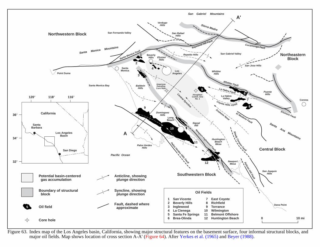
Northwestern Block
Southwestern Block
NortheasternBlock
Central Block
LosAngeles
LongBeach
Corona
BeverlyHills
SantaMonica
120° 118° 116°
36°
34°
32°
SantaBarbara
San Diego
Los AngelesBasin
California
Santa Monica Mountains
Santa Ana Mountains
VerdugoHills
San RafaelHills
Repetto HillsElysian
Hills
BaldwinHills
DominguezHills
Palos VerdesHills
SignalHill
HuntingtonBeachMesa
San JoaquinHills
NewportMesa
San Jose Hills
PuenteHills
WhittierHills
Sierra MadreSan Fernando Valley
Santa Monica Bay
Point Dume
Dana Point
San Gabriel Valley
La HabraValley
Whittier Fault
El Modeno Fault
San Gabriel Mountains
Pacific Ocean
Shady
Canyon
Fault
Coyote Hills Uplift
A
A'
Anaheim Nose
Palos Verdes Hills Fault Pelican Hill Fault
Santa Monica Fault
Newport-Inglewood Fault
Raymond Hill FaultCucamonga Fault
La Habra Fault
Elsinore Fault
Central Syncline
Fault, dashed where approximate
Anticline, showing plunge direction
Syncline, showing plunge direction
Figure 63. Index map of the Los Angeles basin, California, showing major structural features on the basement surface, four informal structural blocks, andmajor oil fields. Map shows location of cross section A-A' (Figure 64). After Yerkes et al. (1965) and Beyer (1988).
0 10 mi
Potential basin-centered gas accumulation
Boundary of structural block
Oil field
Core hole
1
2
3
4
56
7
89
11
12
10
123456
San VicenteBeverly HillsInglewoodLa CienegaSanta Fe SpringsBrea-Olinda
789
101112
East CoyoteRichfieldTorranceWilmingtonBelmont OffshoreHuntington Beach
Oil Fields
5
AmericanPetrofinaCore Hole
HoughtonComm. One
No. 1
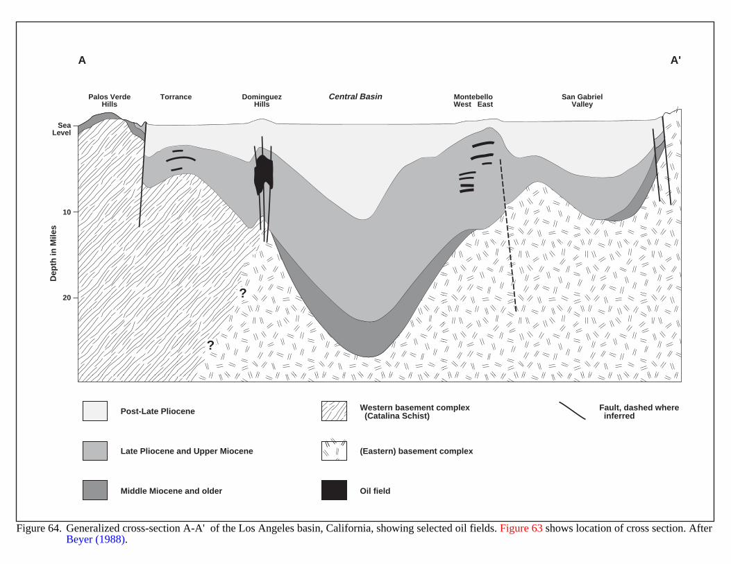
Palos VerdeHills
Torrance MontebelloWest East
DominguezHills
Central Basin San GabrielValley
SeaLevel
10
20
Dep
th in
Mile
sA A'
?
?
Figure 64. Generalized cross-section A-A' of the Los Angeles basin, California, showing selected oil fields. Figure 63 shows location of cross section. AfterBeyer (1988).
Post-Late Pliocene
Late Pliocene and Upper Miocene
Middle Miocene and older
Western basement complex (Catalina Schist)
Fault, dashed where inferred
(Eastern) basement complex
Oil field
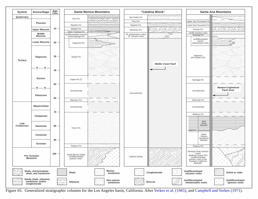
System
QuaternaryPico Fm
Pico Fm
Repetto Fm
Monterey Fm
"B" sedimentary rocks/"B" volcanic rocks
Disconformity
San Pedro Fm
Upper San Fernando Fm
Lower San Fernando Fm
Puente Fm
Santiago Fm
Silverado Fm
Williams Fm
Ladd Fm
HolzShale
Member
BakerCanyon
SandstoneMember
Undiff volcanic rocksTopanga Fm
Vaquerosand Sespe Fms
Undifferentiatedmarine
sedimentary rocks
Repetto Fm
Vaqueros Fm
Sespe Fm
Llajas Fm (?)
Martinez Fm
Chico Fm
Trabuco Fm Trabuco Fm
Santa Monica Slate/Undifferentiatedgranitic rocks
Catalina Schist
Santiago Peak volcanicrocks/
Bedford Canyon Fm/Undifferentiated
granitic rocks of theSouthern California
Batholith
Unconformity
Unconformity
Unconformity
Unconformity
Modelo Fm
Upper Topanga FmUndifferentiated volcanic
rocks/Topanga Fm
Pliocene
Upper Miocene
Lower Miocene
Oligocene
Eocene
Paleocene
Maastrichtian
Campanian
Santonian
Coniacian
Turonian
MiddleMiocene
Tertiary
LateCretaceous
Pre-TuronianMesozoic
Series/Stage Age(mya) Santa Monica Mountains Santa Ana Mountains"Catalina Block"
Malibu Coast Fault
Newport-InglewoodFault Zone
10
20
30
40
50
60
70
80
90
100
? ?
? ?
Shale, cherty/nodular shale, and sandstone
Sandy shale, siltstone, sandstone, and/or conglomerate
Shale
Siltstone
Marine sandstone
Non-marine sandstone
Conglomerate
Breccia
Undifferentiated volcanic rocks
Undifferentiated metamorphic rocks
Schist or slate
Undifferentiated igneous rocks
Figure 65. Generalized stratigraphic columns for the Los Angeles basin, California. After Yerkes et al. (1965), and Campbell and Yerkes (1971).
148
MESOZOIC RIFT BASINS (EASTERN U.S.)
GEOLOGIC SETTING
The Mesozoic rift basins of eastern North America formed in response to the break-up and separation of Pangaeain late Paleozoic to early Mesozoic time. Rift basins formed simultaneously on both the North Atlantic and Euro-African plates (Pyron, 1998). These basins consist of elongate, asymmetric, half-graben structures which containthick Triassic through lower Jurassic clastic, evaporite and volcanic rocks. The basin fill rests unconformably oncrystalline basement formed during the Acadian and Alleghenian orogenies. Sedimentary rock types include reddish-brown mudstones, coarse-grained "border" conglomerates, arkosic sandstones, siltstones, gray-black lacustrine shales,evaporites, and coal. Tholeiitic basalt flows, sills and dikes are also common. On-shore rift basins, both exposed (inthe Piedmont and Blue Ridge Provinces) and inferred (in the Coastal Plain), extend from Georgia to Massachusettsand cover about 42,700 square miles (Figure 66). Individual basins range from 24 square miles (Taylorsville basin)to over 3,100 square miles (Newark basin) in area. Offshore basins extend from Nova Scotia to the Florida Panhandle(Figure 67). The rift basins generally trend northeast, approximately perpendicular to the initial rifting of NorthAmerica and Africa (Klitgord and Behrendt, 1977).
The tectonic history of the basins includes 5 stages:
1) Permian through Triassic: crustal thinning along the eastern margin of the North American continent. Thisis the earliest stage of Pangaea breakup.
2) Middle Triassic: rifting and crustal extension. Late Triassic clastic deposition into subsiding basins.
3) Early Jurassic: extension and clastic deposition in basins along tholeiitic basalt flows and intrusions.
4) Middle Jurassic: sea-floor spreading and development of the Mid-Atlantic ridge system.
5) Late Jurassic to present: lithospheric cooling, plate subsidence, and marine transgression with developmentof a passive continental margin (Schultz, 1988).
The depositional history of a typical onshore Mesozoic rift basin of eastern North America includes four phases:
1) Formation of a rift graben along a listric boundary fault. Alluvial fans form along the upthrown walls andcoalesce into laterally extensive deposits of fanglomerate, and finer-grained sediments near the basin center.Conglomerates interfinger with sandstones and siltstones. Internal basin drainage produces intermittentplayas with evaporite deposits.
2) Tectonic subsidence of the basin ends. Alluvial fans become reworked; coarse to fine sediments enter fromoutside the rift structure. Internal drainage results in the formation of a lake in the basin center. Vegetationflourishes along the lake margins and provides organic material for sedimentation. Feeder streams depositcoarse sands and fanglomerates interfingered with lacustrine sediments.
3) Fluvial and lacustrine sands become reworked and re-deposited parallel to the long axis of the basin. Diabasedikes, sills and sheets intrude along zones of weakness. The magma causes regional heating of the basin andconsequent thermal maturation of organic sediments.
4) Recent uplifting, tilting, and regional erosion created the present day geology. In many offshore basins,evaporite deposition followed continental deposition. During Cretaceous and Tertiary time, marinesediments covered the continental rocks (Pyron, 1998).
149
HYDROCARBON PRODUCTION
There is no hydrocarbon production from any Mesozoic rift basin in the eastern U.S. Seventy years ofexploratory drilling in the rift system has yielded numerous shows of oil and gas but no commercial hydrocarbons.
EVIDENCE FOR BASIN-CENTERED GAS
Other Mesozoic rift basins are productive, including the Ghadames basin in Algeria (Northeast Africa), the Cuyobasin in Argentina (South America), the North Sea (Europe), and the Jeanne d'Arc basin (Canada). Rift basins offerattractive exploration targets because the cycle of rifting, sedimentary fill and igneous activity provides reservoirs,source rocks and thermal maturity.
Significant potential exists for basin-centered gas accumulations within thick lacustrine mudstones, blackshales, siltstones, and sandstones in the deep parts of the eastern U.S. rift basins. Geochemical data, including totalorganic carbon (TOC), thermal alteration index (TAI), vitrinite reflectance (Ro), and Tmax measurements, indicate thebasins are thermally mature.
The Newark basin in central New Jersey and southeastern Pennsylvania may contain significant gas reserves.Figure 67 includes maps depicting the geology and structure of this basin; Figure 68 shows basin stratigraphy inthree locations. The Newark forms a part of a larger rift system that also incorporates the Gettysburg and Culpeperbasins and extends from New Jersey southwest to Virginia. The exposed sedimentary section along this system isover 25,000 ft thick and appears gas prone. The Newark has had only three exploratory wells drilled. One wellreached a depth of 10,500 ft and encountered gas shows within a 3,000-ft section of fractured lacustrine shale.
The Danville basin (Virginia-North Carolina) is also gas prone with a 9840 ft thick sedimentary section. TheHartford basin appears to be oil prone (Hubert et al., 1992; Schultz, 1988; Kotra et al., 1988).
Exploration may identify productive basins where suitable reservoir rocks occur. Basins with thin sedimentarysections, such as the Richmond and Taylorsville, would be less attractive exploration targets.
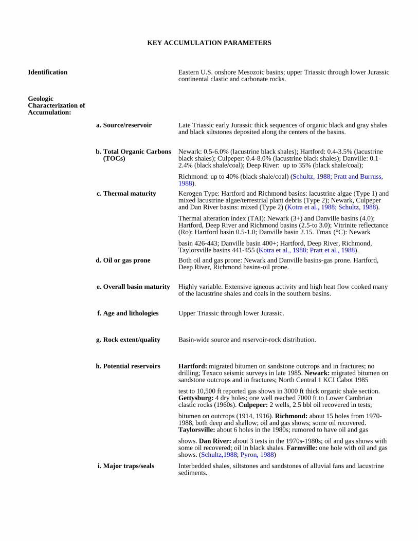
KEY ACCUMULATION PARAMETERS
Identification Eastern U.S. onshore Mesozoic basins; upper Triassic through lower Jurassic continental clastic and carbonate rocks.
Geologic Characterization of Accumulation:
a. Source/reservoir Late Triassic early Jurassic thick sequences of organic black and gray shales and black siltstones deposited along the centers of the basins.
b. Total Organic Carbons (TOCs)
Newark: 0.5-6.0% (lacustrine black shales); Hartford: 0.4-3.5% (lacustrine black shales); Culpeper: 0.4-8.0% (lacustrine black shales); Danville: 0.1-2.4% (black shale/coal); Deep River: up to 35% (black shale/coal);
Richmond: up to 40% (black shale/coal) (Schultz, 1988; Pratt and Burruss, 1988).
c. Thermal maturity Kerogen Type: Hartford and Richmond basins: lacustrine algae (Type 1) and mixed lacustrine algae/terrestrial plant debris (Type 2); Newark, Culpeper and Dan River basins: mixed (Type 2) (Kotra et al., 1988; Schultz, 1988).
Thermal alteration index (TAI): Newark (3+) and Danville basins (4.0); Hartford, Deep River and Richmond basins (2.5-to 3.0); Vitrinite reflectance (Ro): Hartford basin 0.5-1.0; Danville basin 2.15. Tmax (°C): Newark
basin 426-443; Danville basin 400+; Hartford, Deep River, Richmond, Taylorsville basins 441-455 (Kotra et al., 1988; Pratt et al., 1988).
d. Oil or gas prone Both oil and gas prone: Newark and Danville basins-gas prone. Hartford, Deep River, Richmond basins-oil prone.
e. Overall basin maturity Highly variable. Extensive igneous activity and high heat flow cooked many of the lacustrine shales and coals in the southern basins.
f. Age and lithologies Upper Triassic through lower Jurassic.
g. Rock extent/quality Basin-wide source and reservoir-rock distribution.
h. Potential reservoirs Hartford: migrated bitumen on sandstone outcrops and in fractures; no drilling; Texaco seismic surveys in late 1985. Newark: migrated bitumen on sandstone outcrops and in fractures; North Central 1 KCI Cabot 1985
test to 10,500 ft reported gas shows in 3000 ft thick organic shale section. Gettysburg: 4 dry holes; one well reached 7000 ft to Lower Cambrian clastic rocks (1960s). Culpeper: 2 wells, 2.5 bbl oil recovered in tests;
bitumen on outcrops (1914, 1916). Richmond: about 15 holes from 1970-1988, both deep and shallow; oil and gas shows; some oil recovered. Taylorsville: about 6 holes in the 1980s; rumored to have oil and gas
shows. Dan River: about 3 tests in the 1970s-1980s; oil and gas shows with some oil recovered; oil in black shales. Farmville: one hole with oil and gas shows. (Schultz,1988; Pyron, 1988)
i. Major traps/seals Interbedded shales, siltstones and sandstones of alluvial fans and lacustrine sediments.
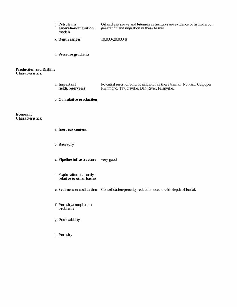
j. Petroleum generation/migration models
Oil and gas shows and bitumen in fractures are evidence of hydrocarbon generation and migration in these basins.
k. Depth ranges 10,000-20,000 ft
l. Pressure gradients
Production and Drilling Characteristics:
a. Important fields/reservoirs
Potential reservoirs/fields unknown in these basins: Newark, Culpeper, Richmond, Taylorsville, Dan River, Farmville.
b. Cumulative production
Economic Characteristics:
a. Inert gas content
b. Recovery
c. Pipeline infrastructure very good
d. Exploration maturity relative to other basins
e. Sediment consolidation Consolidation/porosity reduction occurs with depth of burial.
f. Porosity/completion problems
g. Permeability
h. Porosity
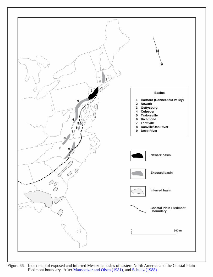
1
2
3
45
67
8
9
123456789
Hartford (Connecticut Valley)NewarkGettysburgCulpeperTaylorsvilleRichmondFarmvilleDanville/Dan RiverDeep River
Basins
Exposed basin
Inferred basin
Coastal Plain-Piedmont boundary
Newark basin
0 500 mi
N
Figure 66. Index map of exposed and inferred Mesozoic basins of eastern North America and the Coastal Plain-Piedmont boundary. After Manspeizer and Olsen (1981), and Schultz (1988).
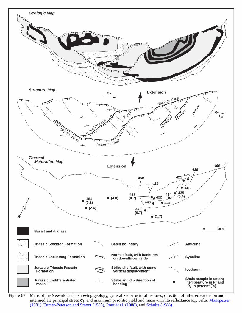
Geologic Map
Structure Map
Thermal Maturation Map
Ramapo Fault
Chalfont FaultHopewell Fault
Flemington Fault
σ2
σ2
Extension
Extension
460
460
435
435
476(0.7)
481(3.2) 440 444
446
428421
422428(0.7)
434 435(0.4)
(1.7)
(4.8)
(2.6)
0 10 mi
N
Triassic Stockton Formation
Triassic Lockatong Formation
Jurassic-Triassic Passaic Formation
Jurassic undifferentiated rocks
Basalt and diabase
Strike and dip direction of bedding
Normal fault, with hachures on downthrown side
Strike-slip fault, with some vertical displacement
Basin boundary
Isotherm
Anticline
Syncline
Shale sample location; temperature in F° and Ro in percent (%)
Figure 67. Maps of the Newark basin, showing geology, generalized structural features, direction of inferred extension andintermediate principal stress σ2, and maximum pyrolitic yield and mean vitrinite reflectance Ro. After Manspeizer (1981), Turner-Peterson and Smoot (1985), Pratt et al. (1988), and Schultz (1988).
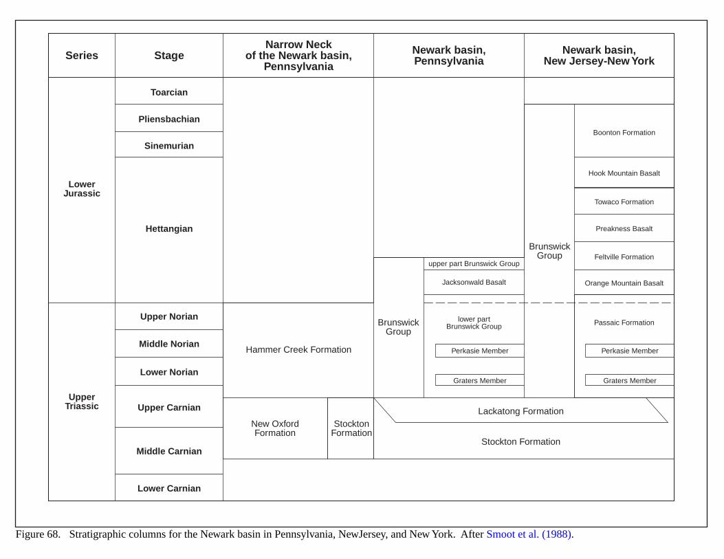
Figure 68. Stratigraphic columns for the Newark basin in Pennsylvania, NewJersey, and New York. After Smoot et al. (1988).
Series StageNarrow Neck
of the Newark basin,Pennsylvania
Newark basin,Pennsylvania
Newark basin,New Jersey-New York
LowerJurassic
Toarcian
Pliensbachian
Sinemurian
Hettangian
Hammer Creek Formation
Lackatong Formation
BrunswickGroup
BrunswickGroup
upper part Brunswick Group
lower partBrunswick Group
Perkasie Member
Graters Member
Perkasie Member
Graters Member
Jacksonwald Basalt
Boonton Formation
Hook Mountain Basalt
Towaco Formation
Preakness Basalt
Feltville Formation
Orange Mountain Basalt
Passaic Formation
New OxfordFormation
StocktonFormation
Stockton Formation
Upper Norian
Middle Norian
Lower Norian
Upper Carnian
Middle Carnian
Lower Carnian
UpperTriassic
155
MICHIGAN BASIN (ST. PETER SANDSTONE)
GEOLOGIC SETTING
The Michigan Basin is a circular-shaped intracratonic basin covering about 80,000 square miles (Catacosinos andDaniels, 1991). Structural boundaries of the basin include the Canadian Shield on the north, the Algonquin Arch onthe east, the Findlay Arch on the south and east, and the Kankakee and Wisconsin Arches on the south and west(Figure 69). The basin contains Paleozoic marine sediments overlying Precambrian basement (Figures 69 and 70).
The Middle Ordovician St. Peter Sandstone consists of massive sandstones interbedded with thinner dolomites(Figure 70). Deposition of this transgressive marine succession occurred in peritidal to storm-dominated outer-shelfenvironments (Catacosinos and Daniels, 1991). In the center of the Michigan Basin, the St. Peter conforms to andinterfingers with the Trempeleau and Prairie du Chien Formations; however, at the basin margins, the sandstone liesunconformably over underlying units (Figure 70). Similarly, at the basin center the St. Peter grades to the overlyingGlenwood Formation, but rests unconformably over underlying units at the basin margins. The St. Peter thickens toalmost 1,100 ft in the basin center (Figure 71).
The quartzose sandstones of the St. Peter are fine- to medium-grained and cemented with silica and dolomite.Diagenesis has generally reduced porosities to less than 3%, but locally they may reach 10 to 15%. Porosityreduction occurred early in the burial history of the St. Peter (Drzewiecki et al., 1994). The formation containsseveral repetitive sequences that reflect the transgressive and highstand cycles resulting from major subsidence andstructural movement within the basin. The sequences appear as wireline log signatures and corresponding lithologies(Figure 72) (Dott and Nadon, 1992). The repetition of sandstone, claystone, and dolomite has not only influenced thediagenetic banding of the sandstone reservoirs, but also has compartmentalized the reservoir pressures.
Sandstone permeability ranges from 1.0 to >100 md (Figure 73) (Bahr et al., 1994).
HYDROCARBON PRODUCTION
The St. Peter has historically had some exploration, but well penetration and testing occurred only in theusually tight upper part. Over 36 gas fields have been discovered in the Glenwood-St. Peter “Deep Play” since thelate 1980s (Barnes et al., 1992). Production depths vary from about 5,000 to 11,500 ft. Falmouth field produced 5.1BCF from 1987 to 1990, and some estimates place the per-well reserves at 2.0 to 14 BCF per 640 acre spacing.
Tests within the St. Peter Sandstone indicate overpressure exceeds 300 psi (Figure 73). Dott and Nadon (1992)believe overpressuring in the formation resulted from hydraulic head created during Wisconsinan glaciation. Bahr etal. (1994) compared brine heads in the basin to ground surface elevations and found a large area of overpressuresoccurring within the St. Peter and Glenwood formations west and north of Saginaw Bay. Figure 71 shows themapped area of overpressure in the St. Peter. Bahr’s results showed an apparent association of vertical variations inoverpressures with vertical variations in permeabilities, which possibly indicates a stacked system of smallercompartments within a larger compartment. Figure 72 illustrates the repetitive depositional sequences within the St.Peter that could represent the smaller pressure compartments within the reservoir’s megacompartment.
Most traps are structural, and consist of several-mile long anticlines having closures of 20 to 80 ft west of aPrecambrian rift and 100 to 200 ft east of the rift (Figure 71). Stratigraphic traps potentially exist, and fracturesystems may also be present.
Organic-rich shales in the Ordovician Foster Formation probably source the St. Peter Sandstone.

156
EVIDENCE FOR BASIN-CENTERED GAS
Vitrinite reflectance data suggests the Michigan Basin Ordovician section is thermally mature (Cercone andPollack, 1991); the authors noted that the present-day geothermal gradient and overburden depth could not account forthe maturation and concluded that a steeper gradient with an overburden composed of fluvial-deltaic sediments wouldcreate a tighter seal to cook the organic material.
Although structure controls most gas production from the St. Peter, mapping the internal depositional anddiagenetic sequences could identify stratigraphically controlled reserves (Dott and Nadon, 1992; Winter et al., 1995).If a seal exists, the erosional limit of the St. Peter Sandstone may hold a regional stratigraphic pinch-out play.
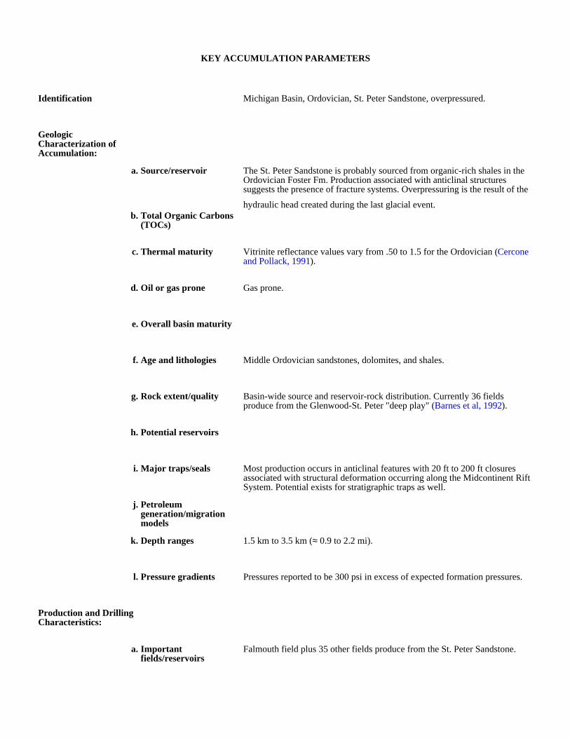
KEY ACCUMULATION PARAMETERS
Identification Michigan Basin, Ordovician, St. Peter Sandstone, overpressured.
Geologic Characterization of Accumulation:
a. Source/reservoir The St. Peter Sandstone is probably sourced from organic-rich shales in the Ordovician Foster Fm. Production associated with anticlinal structures suggests the presence of fracture systems. Overpressuring is the result of the
hydraulic head created during the last glacial event.b. Total Organic Carbons
(TOCs)
c. Thermal maturity Vitrinite reflectance values vary from .50 to 1.5 for the Ordovician (Cercone and Pollack, 1991).
d. Oil or gas prone Gas prone.
e. Overall basin maturity
f. Age and lithologies Middle Ordovician sandstones, dolomites, and shales.
g. Rock extent/quality Basin-wide source and reservoir-rock distribution. Currently 36 fields produce from the Glenwood-St. Peter "deep play" (Barnes et al, 1992).
h. Potential reservoirs
i. Major traps/seals Most production occurs in anticlinal features with 20 ft to 200 ft closures associated with structural deformation occurring along the Midcontinent Rift System. Potential exists for stratigraphic traps as well.
j. Petroleum generation/migration models
k. Depth ranges 1.5 km to 3.5 km (≈ 0.9 to 2.2 mi).
l. Pressure gradients Pressures reported to be 300 psi in excess of expected formation pressures.
Production and Drilling Characteristics:
a. Important fields/reservoirs
Falmouth field plus 35 other fields produce from the St. Peter Sandstone.

b. Cumulative production Falmouth field has produced in excess of 5.1 bcf from 1987 to 1990.
Economic Characteristics:
a. Inert gas content None
b. Recovery Good to moderate.
c. Pipeline infrastructure Good
d. Exploration maturity relative to other basins
Mature basin based on later Paleozoic exploration and production.
e. Sediment consolidation Good to moderate consolidation.
f. Porosity/completion problems
Low porosities and variable permeabilities may require stimulation of the reservoir.
g. Permeability 0.01 to 100 md
h. Porosity 3 to 10%
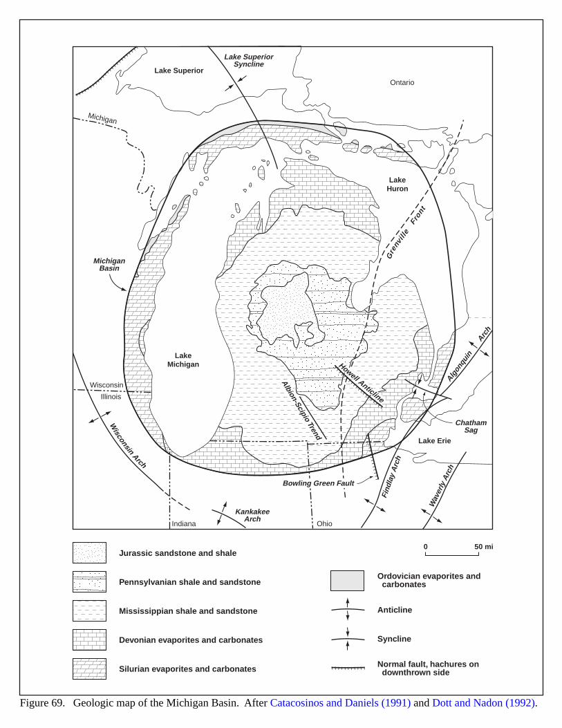
LakeMichigan
LakeHuron
Lake Erie
Lake Superior
Illinois
Indiana Ohio
Wisconsin
Ontario
Michigan
Find
lay
Arc
h
Wav
erly
Arc
h
KankakeeArch
ChathamSag
Algon
quin A
rch
Wisconsin
Arch
MichiganBasin
Gre
nvill
eFr
ont
dner
Toi
picS
-noi
blA
enilcit
nAllewoH
Lake SuperiorSyncline
Bowling Green Fault
0 50 mi
Figure 69. Geologic map of the Michigan Basin. After Catacosinos and Daniels (1991) and Dott and Nadon (1992).
Jurassic sandstone and shale
Ordovician evaporites and carbonates
Silurian evaporites and carbonates
Devonian evaporites and carbonates
Mississippian shale and sandstone
Pennsylvanian shale and sandstone
Anticline
Syncline
Normal fault, hachures on downthrown side
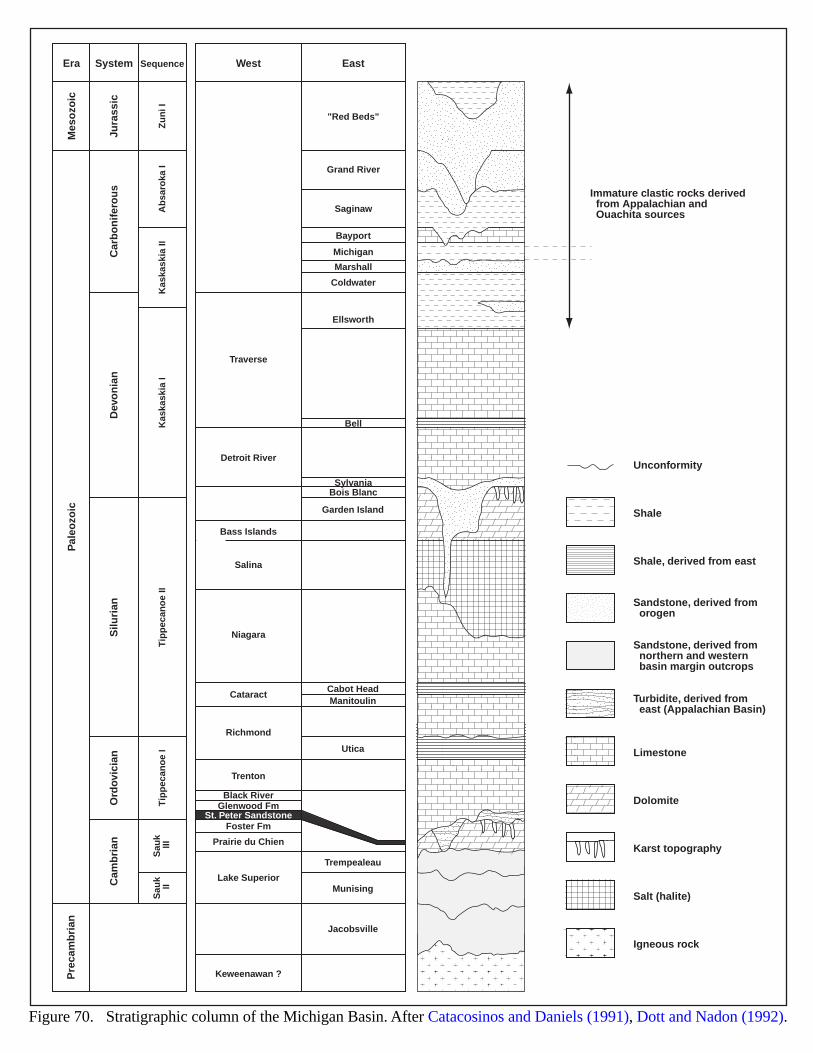
Mes
ozo
ic
Dev
on
ian
Silu
rian
Ord
ovic
ian
Cam
bri
anC
arb
on
ifer
ou
sJu
rass
ic
Traverse
"Red Beds"
Saginaw
Bayport
Michigan
Marshall
Coldwater
Ellsworth
Bell
SylvaniaBois Blanc
Garden Island
Cabot HeadManitoulin
Utica
Trempealeau
Munising
Jacobsville
Grand River
Detroit River
Bass Islands
Salina
Niagara
Cataract
Richmond
Trenton
Prairie du Chien
Foster Fm
Lake Superior
Keweenawan ?
Black RiverGlenwood Fm
St. Peter Sandstone
Zu
ni I
Ab
saro
ka I
Kas
kask
ia II
Kas
kask
ia I
Tip
pec
ano
e II
Tip
pec
ano
e I
Sau
k II
IS
auk
II
Pal
eozo
icP
reca
mb
rian
Era System Sequence West East
Immature clastic rocks derived from Appalachian and Ouachita sources
Shale
Shale, derived from east
Unconformity
Limestone
Dolomite
Karst topography
Salt (halite)
Igneous rock
Sandstone, derived from orogen
Sandstone, derived from northern and western basin margin outcrops
Turbidite, derived from east (Appalachian Basin)
Figure 70. Stratigraphic column of the Michigan Basin. After Catacosinos and Daniels (1991), Dott and Nadon (1992).
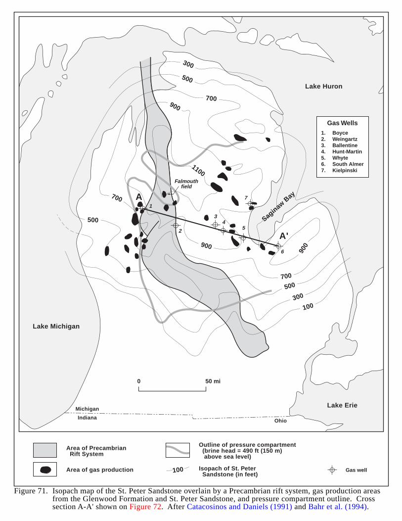
Michigan
Indiana Ohio
Lake Michigan
Lake Huron
Saginaw B
ay
Lake Erie
300
300
500
500
500
700
700
700
900900
900
1100
100
Falmouthfield
1
2
34
5
6
7A
A'
Figure 71. Isopach map of the St. Peter Sandstone overlain by a Precambrian rift system, gas production areasfrom the Glenwood Formation and St. Peter Sandstone, and pressure compartment outline. Crosssection A-A' shown on Figure 72. After Catacosinos and Daniels (1991) and Bahr et al. (1994).
Area of Precambrian Rift System
Area of gas production
Outline of pressure compartment (brine head = 490 ft (150 m) above sea level)
Isopach of St. Peter Sandstone (in feet)
100
0 50 mi
Gas well
1.2.3.4.5.6.7.
BoyceWeingartzBallentineHunt-MartinWhyteSouth AlmerKielpinski
Gas Wells
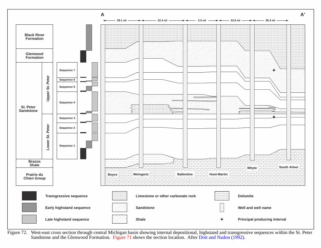
Black RiverFormation
A A'
GlenwoodFormation
St. PeterSandstone
Up
per
St.
Pet
erL
ow
er S
t. P
eter
Prairie duChien Group
BrazosShale
Sequence 7
Sequence 6
Sequence 5
Sequence 4
Sequence 3
Sequence 2
Sequence 1
39.1 mi 22.4 mi 2.5 mi 23.6 mi 30.4 mi
Boyce Ballentine Hunt-Martin
Whyte South Almer
Weingartz
Figure 72. West-east cross section through central Michigan basin showing internal depositional, highstand and transgressive sequences within the St. PeterSandstone and the Glenwood Formation. Figure 71 shows the section location. After Dott and Nadon (1992).
Limestone or other carbonate rock
Sandstone
Shale
Transgressive sequence
Early highstand sequence
Late highstand sequence
Dolomite
Well and well name
Principal producing interval
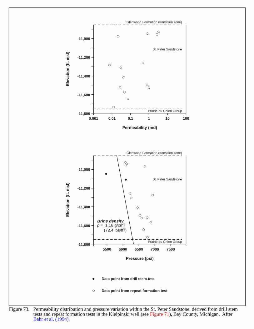
Brine densityρ = 1.16 g/cm3
(72.4 lbs/ft3)
St. Peter Sandstone
Glenwood Formation (transition zone)
Prairie du Chien Group
Prairie du Chien Group
St. Peter Sandstone
Glenwood Formation (transition zone)
5500 6000 6500
Pressure (psi)
7000 7500
-11,000
-11,200
-11,400
-11,600
-11,8000.001 0.01 0.1
Permeability (md)
Ele
vati
on
(ft
. msl
)
-11,000
-11,200
-11,400
-11,600
-11,800
Ele
vati
on
(ft
. msl
)
1 10 100
Figure 73. Permeability distribution and pressure variation within the St. Peter Sandstone, derived from drill stemtests and repeat formation tests in the Kielpinski well (see Figure 71), Bay County, Michigan. After Bahr et al. (1994).
Data point from drill stem test
Data point from repeat formation test
164
MID-CONTINENT RIFT
GEOLOGIC SETTING
The Mid-Continent Rift is a 57,000 square mile horst and graben system located in the north-central U.S. Itfollows an 800-mile long north-northeasterly trend from south-central Kansas to northeastern Minnesota,northwestern Wisconsin, the western part of the Upper Peninsula of Michigan, and into central Michigan(Figure 74) (Palacas, 1995). Precambrian (Keweenawan) in age, this feature represents a failed continental riftcharacterized by broad horst blocks composed of layered basalts and flanked by high-angle normal faults that form theboundaries of adjacent sediment-filled half-grabens (Palacas, 1995). Development of the rift occurred approximately1.1 billion years before present (Dickas, 1986). Dickas (1986) mapped the rift extent by recognizing significantgravity and magnetic anomalies throughout the trend. Newell et al. (1993) noted rejuvenation of some structuralfeatures by steeply dipping reverse faults, where the central horst has thrust over the basin margin.
Stratigraphy appears generally similar along the rift complex, based on outcrop descriptions and logs for wellsthat have penetrated rift sediments (Figure 75). Sedimentary rocks in the Mid-Continent rift include arkosic andfeldspathic sandstones, conglomerates, siltstones, and micaceous red, green and gray shales deposited in marine(Scott, 1966), alluvial plain (Dickas, 1986), and alluvial fan and lacustrine environments (Daniels, 1982; White andWright, 1960; Tryhorn and Ojakangas, 1972; Kalliokoski, 1982; Catacosinos, 1973; and Fowler and Kuenzi, 1978).Layered basalts are common within the rift and compose a central horst block.
The Defiance basin in Iowa is one of the deepest in the rift system. Geophysical modeling indicates 32,800 ft ofsediments (Anderson and Black, 1982). An exploratory well drilled in Iowa penetrated 1,355 ft of Keweenawanclastics, 55% of which were red-brown shales (Dickas, 1986). Two other exploratory wells penetrated significantthicknesses of Mid-Continent rift strata (Figure 74): the Texaco No. 1 Poersch (11,301 ft total depth/8,455 ft of riftstrata penetrated) in northeastern Kansas; and the Amoco No. 1 Eischeid (17,851 ft total depth/14,898 ft of rift stratapenetrated) in west-central Iowa (Newell et al., 1993). Five wells have penetrated the Precambrian Nonesuch Shaleand equivalents within the rift.
Major traps or seals include interbedded shales, siltstones, layered basalts, and fault gouge within the NonesuchFormation, and tight horizons in the overlying Freda Sandstone and Bayfield Group (Figure 75).
HYDROCARBON PRODUCTION
There is no significant hydrocarbon production within the rift. In 1933, operators produced small amounts of oilfrom fractured Precambrian quartzites in central Kansas, at the southern end of the rift trend. Paleozoic source rocksprobably expelled this oil, which then migrated laterally into the Precambrian rocks along structural highs (Walters,1953).
165
EVIDENCE FOR BASIN-CENTERED GAS
The Texaco No. 1-31 Poersch encountered several shows of oil and gas during drilling and testing (Paul et al.,1985). Total organic carbon (TOC) values from the Amoco No. 1 Eischeid in Iowa ranged up to 1.4%, but thesection is overmature (average Tmax = 503° C). In southeastern Minnesota, the Lonsdale No. 65-1 well encountereddark gray mudstone of the Solor Church (Nonesuch) Formation, and TOC values varied from 0.13% to 1.77%(Palacas, 1995); the average Tmax was 494° C (Hatch and Morey, 1984; 1985). In 1929, a cable-tool rig drilled 822ft of Precambrian carbonaceous shales and sandstones and had some oil and gas shows (Newell et al., 1988). Thiswell was 21 miles northeast of the Texaco No. 1 Poersch well.
The Precambrian Nonesuch Fm and equivalents evidently have hydrocarbon generative potential throughout therift system. The interval contains 250 to 700 ft of interbedded, laminated, dark gray to black siltstone, silty shale andsandstone. The silty shale contains TOC values averaging 0.6% and reaching a maximum of 3% (Imbus et al., 1990;Pratt et al., 1991). The greatest TOC values in the Nonesuch and equivalents occur near the middle of the unit andtoward the eastern end of the rift system in northern Michigan.
Palacas (1995) reported that the Nonesuch generated oil and gas from type I and type II kerogens in the deeperparts of several of the rift basins. Thermal maturity was sufficient to crack oils into gaseous hydrocarbons in theIowa and Minnesota segments of the rift. He concluded that two phases of hydrocarbon generation occurred, oneduring the early phase of rift extension, and the second during a compressional phase after the deposition of Paleozoicsediments. Remigration of hydrocarbons probably occurred during the second stage.
Newell et al. (1993) measured a present day geothermal gradient of 15.6 °F per 1,000 ft in the 1-4 Finn well innortheastern Kansas (Figure 76); the bottom-hole temperature at 3,974 ft was 116 °F. Thus, bottom-holetemperatures in deeply buried rift sediments should have sufficed for hydrocarbon generation. No pressure data isknown to exist for wells drilled into the Nonesuch or equivalent rocks (K.D. Newell, Kansas Geological Survey,1999, personal communication).
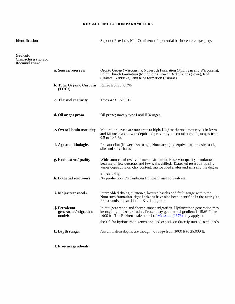
KEY ACCUMULATION PARAMETERS
Identification Superior Province, Mid-Continent rift, potential basin-centered gas play.
Geologic Characterization of Accumulation:
a. Source/reservoir Oronto Group (Wisconsin), Nonesuch Formation (Michigan and Wisconsin), Solor Church Formation (Minnesota), Lower Red Clastics (Iowa), Red Clastics (Nebraska), and Rice formation (Kansas).
b. Total Organic Carbons (TOCs)
Range from 0 to 3%
c. Thermal maturity Tmax 423 – 503° C
d. Oil or gas prone Oil prone; mostly type I and II kerogen.
e. Overall basin maturity Maturation levels are moderate to high. Highest thermal maturity is in Iowa and Minnesota and with depth and proximity to central horst. Ro ranges from 0.5 to 1.43 %.
f. Age and lithologies Precambrian (Keweenawan) age, Nonesuch (and equivalent) arkosic sands, silts and silty shales
g. Rock extent/quality Wide source and reservoir rock distribution. Reservoir quality is unknown because of few outcrops and few wells drilled. Expected reservoir quality varies depending on clay content, interbedded shales and silts and the degree
of fracturing.h. Potential reservoirs No production. Precambrian Nonesuch and equivalents.
i. Major traps/seals Interbedded shales, siltstones, layered basalts and fault gouge within the Nonesuch formation, tight horizons have also been identified in the overlying Freda sandstone and in the Bayfield group.
j. Petroleum generation/migration models
In-situ generation and short distance migration. Hydrocarbon generation may be ongoing in deeper basins. Present day geothermal gradient is 15.6° F per 1000 ft. The Bakken shale model of Meissner (1978) may apply in
the rift for hydrocarbon generation and explulsion directly into adjacent beds.
k. Depth ranges Accumulation depths are thought to range from 3000 ft to 25,000 ft.
l. Pressure gradients

Production and Drilling Characteristics:
a. Important fields/reservoirs
Entire rift trend virtually untested; no production to date.
b. Cumulative production None
Economic Characteristics:
a. Inert gas content Unknownb. Recovery Recoveries would vary depending on permeability, porosity and depth;
diagenetic alteration may increase with depth.
c. Pipeline infrastructure Poor
d. Exploration maturity relative to other basins
Immature
e. Sediment consolidation Most rocks are well indurated.
f. Porosity/completion problems
Silty shales, clay, and arcosic/feldspathic sands have high alteration potential; also may have swelling clays and will produce migrating fines problems. Silty shales and siltstones are interbedded with sands.
g. Permeability
h. Porosity Average porosities range from 4% to 18%.
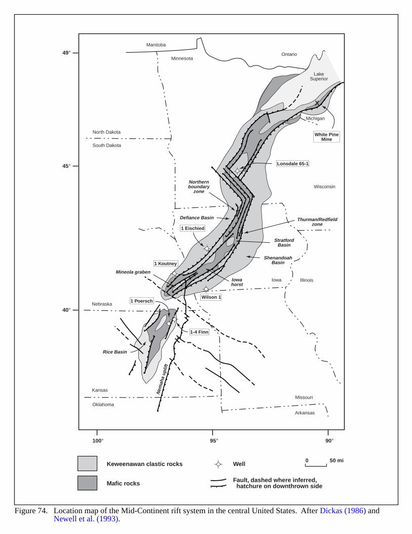
Nebraska
Minnesota
Kansas
Oklahoma
Arkansas
Missouri
Iowa
Wisconsin
North Dakota
Manitoba
Ontario
South Dakota
Michigan
LakeSuperior
1-4 Finn
Illinois
X
49°
45°
40°
100° 95° 90°
Nem
aha
uplif
t
Mineola graben
Iowahorst
Rice Basin
Defiance Basin
ShenandoahBasin
StratfordBasin
Thurman/Redfieldzone
Northernboundary
zone
1 PoerschWilson 1
1 Koutney
1 Eischied
Lonsdale 65-1
White PineMine
0 50 mi
Figure 74. Location map of the Mid-Continent rift system in the central United States. After Dickas (1986) and Newell et al. (1993).
Keweenawan clastic rocks
Mafic rocks
Well
Fault, dashed where inferred, hatchure on downthrown side
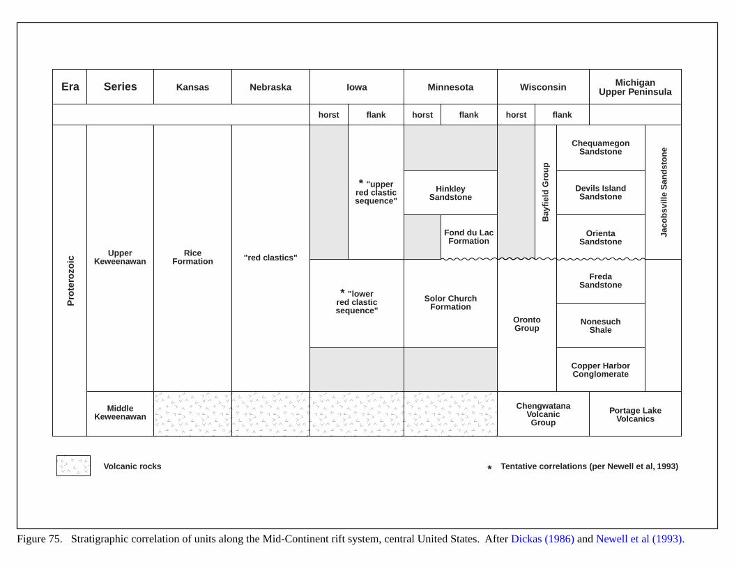
Era Series Kansas
Pro
tero
zoic
UpperKeweenawan
RiceFormation "red clastics"
flankhorst horst horstflank flank
* "lowerred clasticsequence"
Solor ChurchFormation
OrontoGroup
ChequamegonSandstone
Devils IslandSandstone
OrientaSandstone
FredaSandstone
NonesuchShale
Copper HarborConglomerate
ChengwatanaVolcanicGroup
Portage LakeVolcanics
* "upperred clasticsequence"
HinkleySandstone
Bay
fiel
d G
rou
p
Jaco
bsv
ille
San
dst
on
e
Fond du LacFormation
MiddleKeweenawan
Nebraska Iowa Minnesota Wisconsin MichiganUpper Peninsula
Volcanic rocks Tentative correlations (per Newell et al, 1993)*
Figure 75. Stratigraphic correlation of units along the Mid-Continent rift system, central United States. After Dickas (1986) and Newell et al (1993).
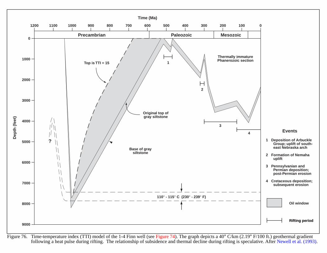
1200 1100 1000 900 800 700 600 500 400 300 200 100 0
0
1000
2000
3000
4000
5000
6000
7000
8000
9000
Time (Ma)D
epth
(fe
et)
Rifting periodRifting period
Oil window
1
2
3
4
Top is TTI = 15
Thermally immaturePhanerozoic section
1
2
3
4
Deposition of Arbuckle Group; uplift of south- east Nebraska arch
Formation of Nemaha uplift
Pennsylvanian and Permian deposition; post-Permian erosion
Cretaceous deposition; subsequent erosion
Events
MesozoicPaleozoicPrecambrian
Original top ofgray siltstone
Base of graysiltstone
?
110° - 115° C (230° - 239° F)
Figure 76. Time-temperature index (TTI) model of the 1-4 Finn well (see Figure 74). The graph depicts a 40° C/km (2.19° F/100 ft.) geothermal gradient following a heat pulse during rifting. The relationship of subsidence and thermal decline during rifting is speculative. After Newell et al. (1993).
171
PARADOX BASIN (CANE CREEK INTERVAL)
GEOLOGIC SETTING
The Paradox Basin extends across southeastern Utah and southwestern Colorado along a roughly northwest-southeast trend. Several structures form its boundaries and contributed sediments: the ancestral Uncompahgre Upliftto the northeast, the Monument Uplift to the southwest, and the Emery Uplift to the northwest (Figure 77) (Baarsand Stevenson, 1981). Figure 78 shows a partial stratigraphy of the basin.
During the Pennsylvanian (Desmoinesian) period, the basin accumulated deposits of algal carbonates andevaporites (halite, gypsum, and potash) which interfingered with clastic deposits shed from surrounding higherregions (mostly the ancestral Uncompahgre Uplift; the present Uncompahgre Plateau formed during the early TertiaryLaramide orogeny). Toward the basin depocenter, evaporite deposits interfinger with siltstones, organic-richdolomites and black shales. Deposition of Uncompahgre alluvium deformed the underlying salts, which creatednorthwest- to southeast-trending anticlines parallel to basement faults (Figure 79) (Hite and Buckner, 1981).
The Cane Creek interval is the 22nd of 29 carbonate cycles identified within the Paradox Member of theHermosa Formation (Figures 78 and 80) (Hite et al., 1984). Three units make up the Cane Creek interval: theuppermost "A" unit of interbedded red siltstone and anhydrite; the "B" unit of black, organic-rich shales anddolomites; and the lowermost "C" unit of interbedded red siltstone and anhydrite. The "B" unit represents the sourceand reservoir rock and varies in thickness from less than 10 ft to almost 30 ft. Combined, the three clastic units arealmost 150 ft thick near the basin depocenter, but pinch out against the ancestral Uncompahgre flank (Morgan,1992). The interval thins in synclines and thickens on anticlines; this occurrence may result from (1) originaldeposition associated with fault movement, (2) structural thickening from small-scale folding and faulting (i.e.,repeat sections), and/or (3) flowage within anhydrite layers (Montgomery, 1992).
HYDROCARBON PRODUCTION:
Most production in the Paradox originates from Ismay and Desert Creek carbonates in the southern part of thebasin. Some structures in the Mississippian Redwall and Leadville limestones also produce hydrocarbons. To date,Cane Creek production has occurred only in the northern part of the basin, and mostly from fractures and fractureintersections on the flanks of anticlines that parallel the ancestral Uncompahgre Uplift. The nature of the fracturingmakes production very sensitive to drilling mud weights and completion techniques (Montgomery, 1992). As aresult, recoveries vary greatly.
Cane Creek wells show significant reservoir overpressuring, at least 6,000 to 6,500 psi at depths of 7,200 to7,500 ft. The overpressuring may result from salt flowage (Montgomery, 1992). Oil is typically sweet, having APIgravities from 43 to 46. Gas associated with oil production is usually flared, because of the lack of pipelines in thearea. The gas is sweet, containing between 1 and 2% nitrogen and/or carbon dioxide.
The # 1 Long Canyon well (9-26S-20E) drilled by Southern Natural Gas has yielded over 1 MBO since 1962. In1991, Columbia Gas completed Kane Spring Federal No. 27-1 (27-15S-19E) in the Cane Creek interval usinghorizontal drilling; cumulative production to 1992 exceeded 100,000 bbls of oil.
172
EVIDENCE FOR BASIN CENTERED-GAS
The Cane Creek interval is rich in organic content and thermally mature. Data from the Gibson Dome well(Figures 79 and 80) shows total organic carbon (TOC) content in the interval to be 3.96 wt%; vitrinite reflectance(Ro) averaged 0.54, and Tmax reached 438° C (Hite et al., 1984). This data indicates the Cane Creek is self-sourced(C.W. Spencer, U.S. Geological Survey, 2000, personal communication). The reservoir/source may communicatewith other organic-rich reservoir/ source rocks.
Traps within the Cane Creek interval appear to be small tightly folded salt structures; stratigraphic traps arepossible. If the salt layers formed impermeable seals, significant overpressures would occur.
Temperatures in Columbia Gas wells in the Kane Spring and Shafer Canyon areas range from 114 to 132° C andprobably indicate too low a reservoir temperature exists for a basin center accumulation to occur (M.S. Wilson,2000, consulting geologist, written communication). However, at greater depth, reservoir temperatures and thermalmaturity would probably be higher, and consequently, a basin center gas accumulation may be present in the deeperparts of the Paradox Basin.
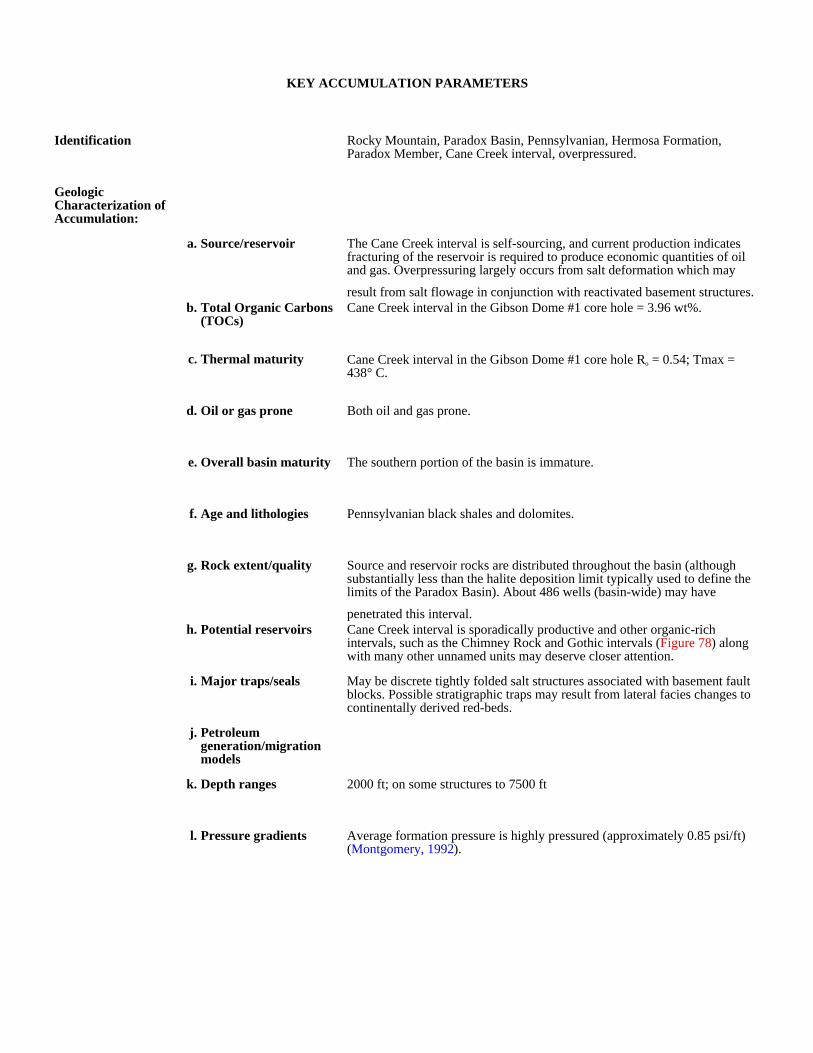
KEY ACCUMULATION PARAMETERS
Identification Rocky Mountain, Paradox Basin, Pennsylvanian, Hermosa Formation, Paradox Member, Cane Creek interval, overpressured.
Geologic Characterization of Accumulation:
a. Source/reservoir The Cane Creek interval is self-sourcing, and current production indicates fracturing of the reservoir is required to produce economic quantities of oil and gas. Overpressuring largely occurs from salt deformation which may
result from salt flowage in conjunction with reactivated basement structures.b. Total Organic Carbons
(TOCs)Cane Creek interval in the Gibson Dome #1 core hole = 3.96 wt%.
c. Thermal maturity Cane Creek interval in the Gibson Dome #1 core hole Ro = 0.54; Tmax = 438° C.
d. Oil or gas prone Both oil and gas prone.
e. Overall basin maturity The southern portion of the basin is immature.
f. Age and lithologies Pennsylvanian black shales and dolomites.
g. Rock extent/quality Source and reservoir rocks are distributed throughout the basin (although substantially less than the halite deposition limit typically used to define the limits of the Paradox Basin). About 486 wells (basin-wide) may have
penetrated this interval.h. Potential reservoirs Cane Creek interval is sporadically productive and other organic-rich
intervals, such as the Chimney Rock and Gothic intervals (Figure 78) along with many other unnamed units may deserve closer attention.
i. Major traps/seals May be discrete tightly folded salt structures associated with basement fault blocks. Possible stratigraphic traps may result from lateral facies changes to continentally derived red-beds.
j. Petroleum generation/migration models
k. Depth ranges 2000 ft; on some structures to 7500 ft
l. Pressure gradients Average formation pressure is highly pressured (approximately 0.85 psi/ft) (Montgomery, 1992).

Production and Drilling Characteristics:
a. Important fields/reservoirs
Bartlett Flat, Cane Creek, Gold Bar, Long Canyon, Shafer Canyon, Wilson Canyon.
b. Cumulative production The Long Canyon well has produced in excess of 1 MMBO since 1962, and the Kane Creek Federal #27-1 has produced in excess of 100 MBO as of 1992 (Montgomery, 1992).
Economic Characteristics:
a. Inert gas content No; from 1.0 % to 3.0 %.
b. Recovery Highly variable
c. Pipeline infrastructure Poor
d. Exploration maturity relative to other basins
e. Sediment consolidation The producing interval is well indurated due to depth of burial.
f. Porosity/completion problems
The reservoir/source rock is fractured and overpressured; as a consequence, heavy weight drilling muds are often used, which may result in formation damage and difficult and costly completions. Production of hypersaline
formation waters has often caused plugging of production tubing and equipment which may in turn give erroneous flow rates and production declines.
g. Permeability Highly variable, fracture permeability.
h. Porosity
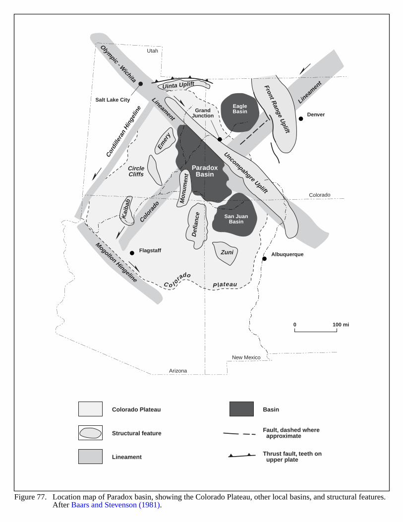
Mogollon Hingeline
Cord
iller
an H
inge
line
Color
ado
Lineamen
t
Olympic - W
ichita
Lineament
Front Range U
plift
San JuanBasin
EagleBasin
Def
ian
ce
Zuni
Kai
bab
CircleCliffs
Emery
Uinta Uplift
Arizona
New Mexico
Utah
Colorado
DenverGrand
Junction
Salt Lake City
FlagstaffAlbuquerque
Uncompahgre Uplift
Mon
umen
t
C o l o
rado
P lateau
ParadoxBasin
Figure 77. Location map of Paradox basin, showing the Colorado Plateau, other local basins, and structural features. After Baars and Stevenson (1981).
0 100 mi
Colorado Plateau
Structural feature
Lineament
Basin
Fault, dashed where approximate
Thrust fault, teeth on upper plate
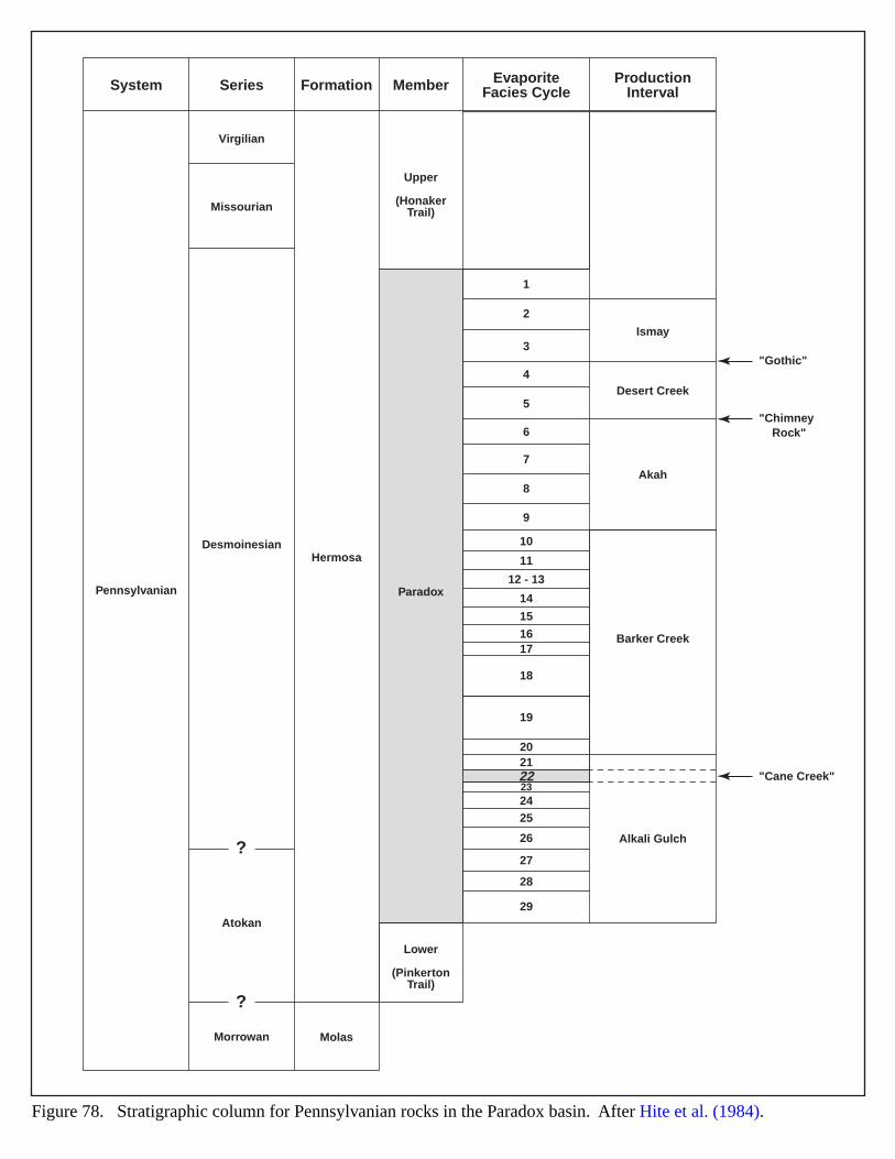
System
Pennsylvanian
Atokan
Morrowan
Virgilian
Upper
(HonakerTrail)
Paradox
Lower
(PinkertonTrail)
Missourian
DesmoinesianHermosa
Ismay
"Gothic"
"Chimney Rock"
"Cane Creek"
Desert Creek
Akah
Barker Creek
Alkali Gulch
Molas
Series Formation Member EvaporiteFacies Cycle
ProductionInterval
?
?
1
2
3
4
5
6
7
8
9
10
11
12 - 13
14
15
1617
18
19
2021
2425
26
27
28
29
2322
Figure 78. Stratigraphic column for Pennsylvanian rocks in the Paradox basin. After Hite et al. (1984).
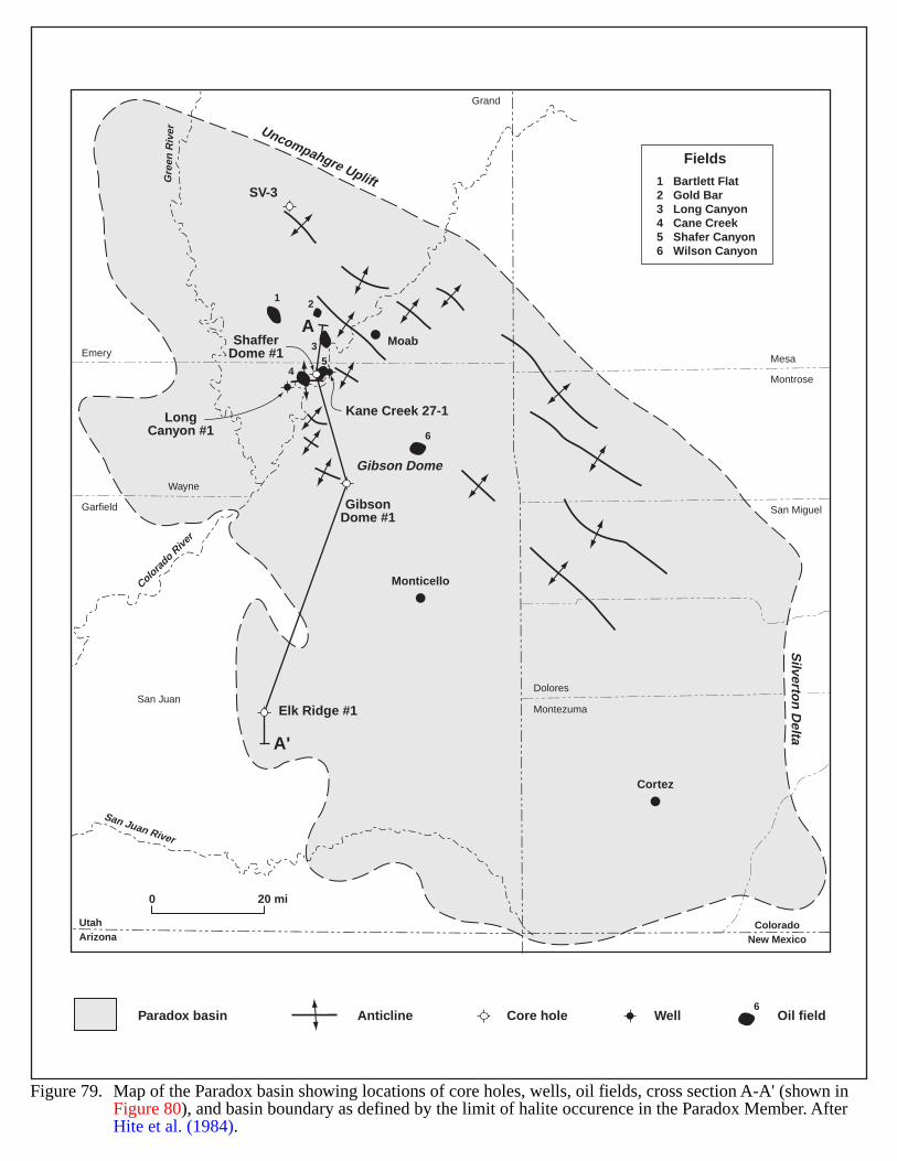
A
A'
Uncompahgre Uplift
Silverto
n D
elta
Gibson Dome
Monticello
Moab
Cortez
UtahArizona
ColoradoNew Mexico
Mesa
Montrose
San Miguel
DoloresSan Juan
Garfield
Wayne
Emery
Grand
Montezuma
Gre
en R
iver
Colora
do Rive
r
San Juan River
12
35
6
4
ShafferDome #1
GibsonDome #1
Elk Ridge #1
LongCanyon #1
Kane Creek 27-1
SV-3123456
Bartlett FlatGold BarLong CanyonCane CreekShafer CanyonWilson Canyon
Fields
0 20 mi
Paradox basin Anticline Core hole Oil fieldWell
Figure 79. Map of the Paradox basin showing locations of core holes, wells, oil fields, cross section A-A' (shown inFigure 80), and basin boundary as defined by the limit of halite occurence in the Paradox Member. After Hite et al. (1984).
6
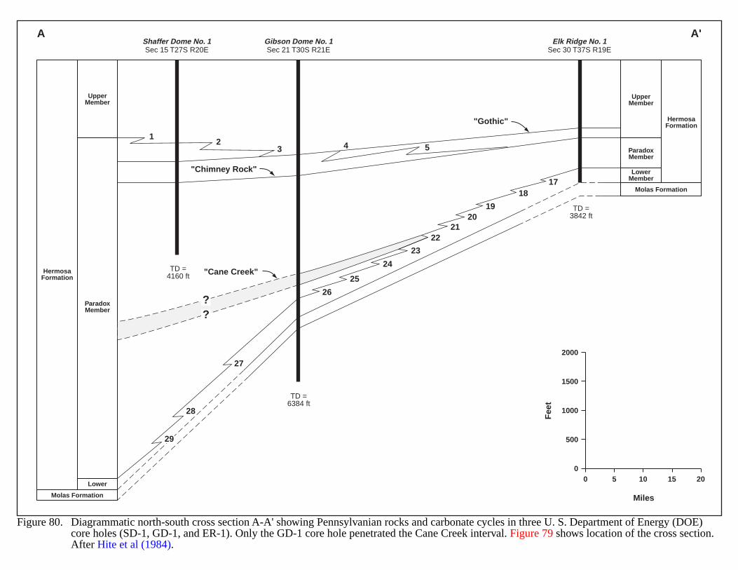
Figure 80. Diagrammatic north-south cross section A-A' showing Pennsylvanian rocks and carbonate cycles in three U. S. Department of Energy (DOE) core holes (SD-1, GD-1, and ER-1). Only the GD-1 core hole penetrated the Cane Creek interval. Figure 79 shows location of the cross section.After Hite et al (1984).
Molas Formation
Molas Formation
Lower
ParadoxMember
ParadoxMember
LowerMember
HermosaFormation
HermosaFormation
UpperMember
UpperMember
12
3 4 5
1718
1920
21
23
24
25
26
27
28
29
22
"Gothic"
"Chimney Rock"
"Cane Creek"TD =4160 ft
TD =6384 ft
TD =3842 ft
??
Elk Ridge No. 1Sec 30 T37S R19E
Gibson Dome No. 1Sec 21 T30S R21E
Shaffer Dome No. 1Sec 15 T27S R20E
A A'
2000
00 5 10 15 20
500
1000
1500
Miles
Fee
t
179
PARK BASINS OF COLORADO
GEOLOGIC SETTING
The Park Basins are located 50 miles west of Denver, in central Colorado. Four mountain regions define thebasin limits: the Front Range to the east; Medicine Bow Mountains to the north; Park, Gore, and Mosquito Rangeson the west; and the Thirty-nine Mile Volcanic Range to the south (Figure 81). Structural or stratigraphic differencesseparate the Park Basin into three intermontane basins–North, Middle, and South Park. Tertiary volcanics of theRabbit Ears Range physically divide the otherwise structurally similar North and Middle Parks. Thirty miles to thesouth lies South Park Basin, which has undergone a more complex structural and stratigraphic history. Precambrianrocks and Tertiary intrusives of the Williams Fork and Vasquez Mountains isolate this basin from North and MiddleParks.
The 50-by 180-mile Park Basin complex is predominantly a north-south trending, asymmetrical syncline. Thecomplex was an uplifted feature of the ancestral Front Range throughout most of the Paleozoic. The narrow synclineformed during the Late Cretaceous to Early Tertiary Laramide orogeny. Tectonism progressed from Late Cretaceousthrust faulting and folding to later episodes of intrusion, volcanism, and reverse and normal faulting. Major thrustsoccur along the northern and eastern margins of the basin and show as much as 20 miles of movement (Maughan,1988). Superimposed within the syncline are high-angle reverse faults (up to 10,000 ft of displacement), normalfaults, tight folds, and volcanic rocks (Figure 81).
The basins preserve from 10,000 to 20,000 ft of sediments (sometimes stacked in thrust plates) (SavantResources LLC Report, 1999). Figure 82 shows stratigraphic columns for each park basin. Sediments of North andMiddle Park Basins are largely Mesozoic sands, shales, and marls (Figure 83). Southwestern South Park exhibits athick Paleozoic sequence of carbonates, shales, and arkosic sandstones (Figure 84). The Laramide orogeny caused aperiod of basin-wide non-deposition, so Tertiary sediments unconformably overlie Cretaceous rocks. The Tertiarysection generally consists of non-marine clastics interspersed with coals and volcanics. Quaternary alluvium reflectsthe present quiescent phase of the basin.
HYDROCARBON PRODUCTION
Exploration has found hydrocarbons in anticlinal folds associated with thrusting in the Upper Jurassic-LowerCretaceous shoreline sands of the North Park Basin (Figure 83). The Colorado Oil and Gas ConservationCommission (1997) recorded a total of 16.5 MMBO and 12.3 BCF from Battleship, Lone Pine, and North and SouthMcCallum fields.
Target basin-centered gas intervals are in the Upper Cretaceous: the Apache Creek Sandstone of the Pierre Shaleand the brittle, calcareous shales of the Niobrara (Figure 82). There are numerous hydrocarbon shows but no recordedproduction from the Apache Creek. The Pierre B sand is probably a sandstone equivalent to the Apache Creek and hasproduced approximately 1.4 MMCFG and 10.5 MBO (Maughan 1988). Fractured shales of the Niobrara Formationhave produced about 278,000 BO and 156 MMCFG from the Delaney Butte, Michigan River, Canadian River,Coalmont, Johnny Moore Mountain, and Carlstrom fields (Colorado Oil and Gas Conservation Commission, 1997).Mallory (1977) provides details of this fracture play.
180
EVIDENCE FOR BASIN-CENTERED GAS
The Apache Creek Formation in South Park has had significant hydrocarbon shows. In 1999 Savant ResourcesLLC evaluated the basin and obtained gas data for the Hunt Tarryall Federal 1-17 well (Figure 84). The companyfound a 24-ft section of the Apache Creek yielded 195 MCFD of pipeline-quality gas. Testing revealed 0.3 md matrixpermeability, 8.3% average porosity, and 0.52 psi/ft pressure gradient, which indicated formation damage. Savantrecalculated open flow for the entire section and found 1,500 to 2,945 MCFD without hydraulic fracturing and 7,344MCFD with induced fracturing.
The Federal 1-17 well data demonstrates Spencer’s (1987) and Surdham’s (1995) characteristics for accumulationof basin-centered gas:
1. Overpressuring of the formation occurs below 10,000 ft. The Apache Creek Sandstone at 11,150 feetdisplayed a pressure gradient of 0.52 psi/ft.
2. Dry hydrocarbons are the fluid-pressuring phase and rarely produce water. The pressure test recovered dry gasof pipeline grade (1021 Btu).
3. Temperature of the overpressured rock is 180-2300 F or greater. The temperature of the Apache CreekSandstone was 2300 F.
4. Source beds can generate hydrocarbons at rates exceeding loss. Minimum vitrinite reflectance (Ro) is 0.6%in oil-producing source beds and greater that 0.7% in gas-producing source beds. Pierre and Upper Niobrarashales exhibit Ro values between 1.3 and 1.4% Ro. With TOC values around 1.3% and S1 + S2 values upto 2.6 mg/gm, these rocks demonstrate additional generation potential.
5. Overpressuring is in tight strata. Permeabilities ranging from 0.18 to 0.4 md typify the tight strata andsuffice for production, after induced fracturing.
Based on available information (such as a net pay of 100 ft and extensive reservoirs in the South Park thrustsheet), Savant Resources (Denver, Colorado, written communication, 1999) calculated gas reserves of 1.4-2.3 TCFin the Apache Creek play. Depth to the Apache Creek is 11,150 feet in the Hunt well and varies widely (Figure 84)(Wellborn, 1977). Similar thrusts containing the prospective horizon at the required depth could create additionalprospects. Notable secondary targets include the Fox Hills Sandstone, the Upper Transition Member of the PierreShale, the Niobrara Formation, the Frontier Sandstone, the Dakota Group, and the Garo (Entrada) Sandstone(Figure 82). Although South Park has had no production to date, a blow-out in the Pierre Shale and hydrocarbonseeps (Elkhorn Thrust, Three Mile Seep, and Willow Creek Pass) indicate a potential for an unconventional deep gasplay. Total organic carbon (C) content for the Pierre Shale ranged from 0.1 to 1.5% (Barker et al., 1996; SavantResources LLC Report, 1999), and 1.4 to 2.1% for the Mowry Shale (Aldy, 1994).
Since the Apache Creek Formation also exists in North and Middle Park, basin-centered gas plays maypotentially occur in those basins as well.
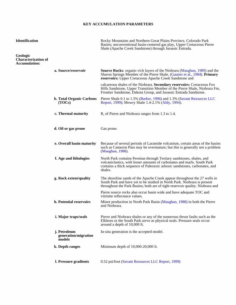
KEY ACCUMULATION PARAMETERS
Identification Rocky Mountains and Northern Great Plains Province, Colorado Park Basins; unconventional basin-centered gas play, Upper Cretaceous Pierre Shale (Apache Creek Sandstone) through Jurassic Entrada.
Geologic Characterization of Accumulation:
a. Source/reservoir Source Rocks: organic-rich layers of the Niobrara (Maughan, 1989) and the Sharon Springs Member of the Pierre Shale. (Gautier et al., 1984). Primary reservoirs: Upper Cretaceous Apache Creek Sandstone and
calcareous shales of the Niobrara. Secondary reservoirs: Cretaceous Fox Hills Sandstone, Upper Transition Member of the Pierre Shale, Niobrara Fm, Frontier Sandstone, Dakota Group, and Jurassic Entrada Sandstone.
b. Total Organic Carbons (TOCs)
Pierre Shale 0.1 to 1.5% (Barker, 1996) and 1.3% (Savant Resources LLC Report, 1999); Mowry Shale 1.4-2.1% (Aldy, 1994).
c. Thermal maturity Ro of Pierre and Niobrara ranges from 1.3 to 1.4.
d. Oil or gas prone Gas prone.
e. Overall basin maturity Because of several periods of Laramide volcanism, certain areas of the basins such as Cameron Pass may be overmature; but this is generally not a problem (Maughan, 1988).
f. Age and lithologies North Park contains Permian through Tertiary sandstones, shales, and volcaniclastics, with lesser amounts of carbonates and marls. South Park contains a thick sequence of Paleozoic arkosic sandstones, carbonates, and shales.
g. Rock extent/quality The shoreline sands of the Apache Creek appear throughout the 27 wells in South Park and have yet to be studied in North Park. Niobrara is present throughout the Park Basins; both are of tight reservoir quality. Niobrara and
Pierre source rocks also occur basin wide and have adequate TOC and vitrinite reflectance values.
h. Potential reservoirs Minor production in North Park Basin (Maughan, 1988) in both the Pierre and Niobrara.
i. Major traps/seals Pierre and Niobrara shales or any of the numerous thrust faults such as the Elkhorn or the South Park serve as physical seals. Pressure seals occur around a depth of 10,000 ft.
j. Petroleum generation/migration models
In-situ generation is the accepted model.
k. Depth ranges Minimum depth of 10,000-20,000 ft.
l. Pressure gradients 0.52 psi/foot (Savant Resources LLC Report, 1999)
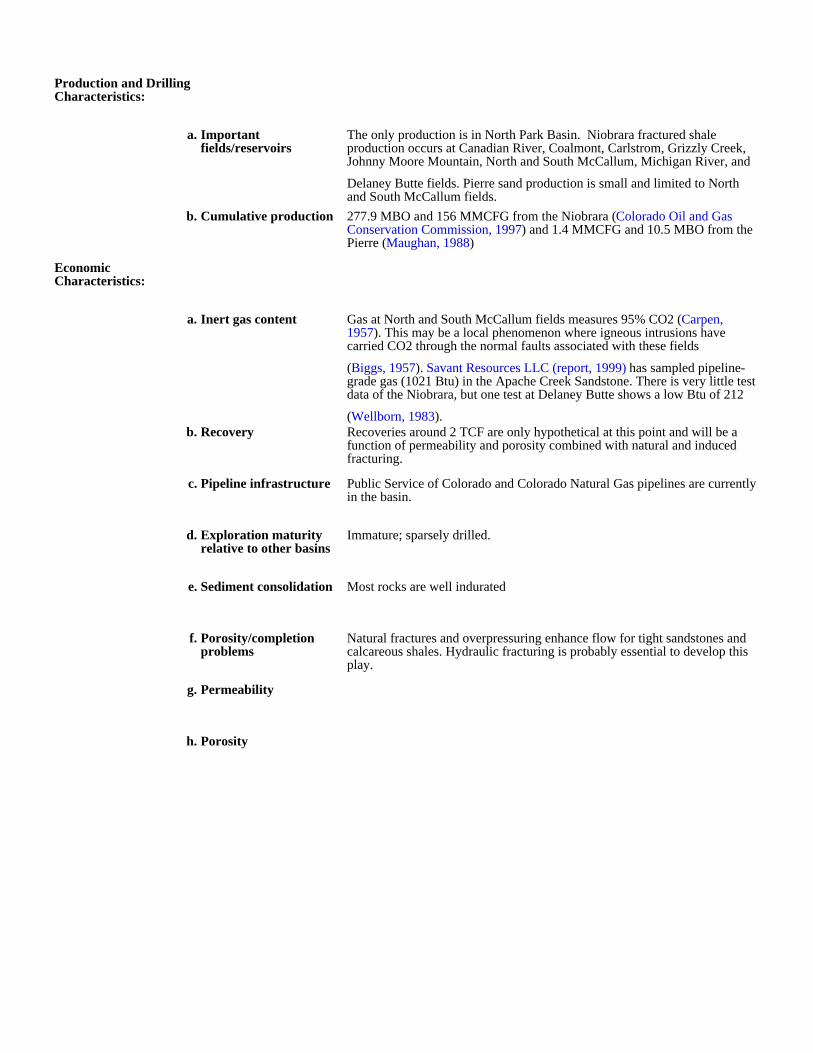
Production and Drilling Characteristics:
a. Important fields/reservoirs
The only production is in North Park Basin. Niobrara fractured shale production occurs at Canadian River, Coalmont, Carlstrom, Grizzly Creek, Johnny Moore Mountain, North and South McCallum, Michigan River, and
Delaney Butte fields. Pierre sand production is small and limited to North and South McCallum fields.
b. Cumulative production 277.9 MBO and 156 MMCFG from the Niobrara (Colorado Oil and Gas Conservation Commission, 1997) and 1.4 MMCFG and 10.5 MBO from the Pierre (Maughan, 1988)
Economic Characteristics:
a. Inert gas content Gas at North and South McCallum fields measures 95% CO2 (Carpen, 1957). This may be a local phenomenon where igneous intrusions have carried CO2 through the normal faults associated with these fields
(Biggs, 1957). Savant Resources LLC (report, 1999) has sampled pipeline-grade gas (1021 Btu) in the Apache Creek Sandstone. There is very little test data of the Niobrara, but one test at Delaney Butte shows a low Btu of 212
(Wellborn, 1983).b. Recovery Recoveries around 2 TCF are only hypothetical at this point and will be a
function of permeability and porosity combined with natural and induced fracturing.
c. Pipeline infrastructure Public Service of Colorado and Colorado Natural Gas pipelines are currently in the basin.
d. Exploration maturity relative to other basins
Immature; sparsely drilled.
e. Sediment consolidation Most rocks are well indurated
f. Porosity/completion problems
Natural fractures and overpressuring enhance flow for tight sandstones and calcareous shales. Hydraulic fracturing is probably essential to develop this play.
g. Permeability
h. Porosity
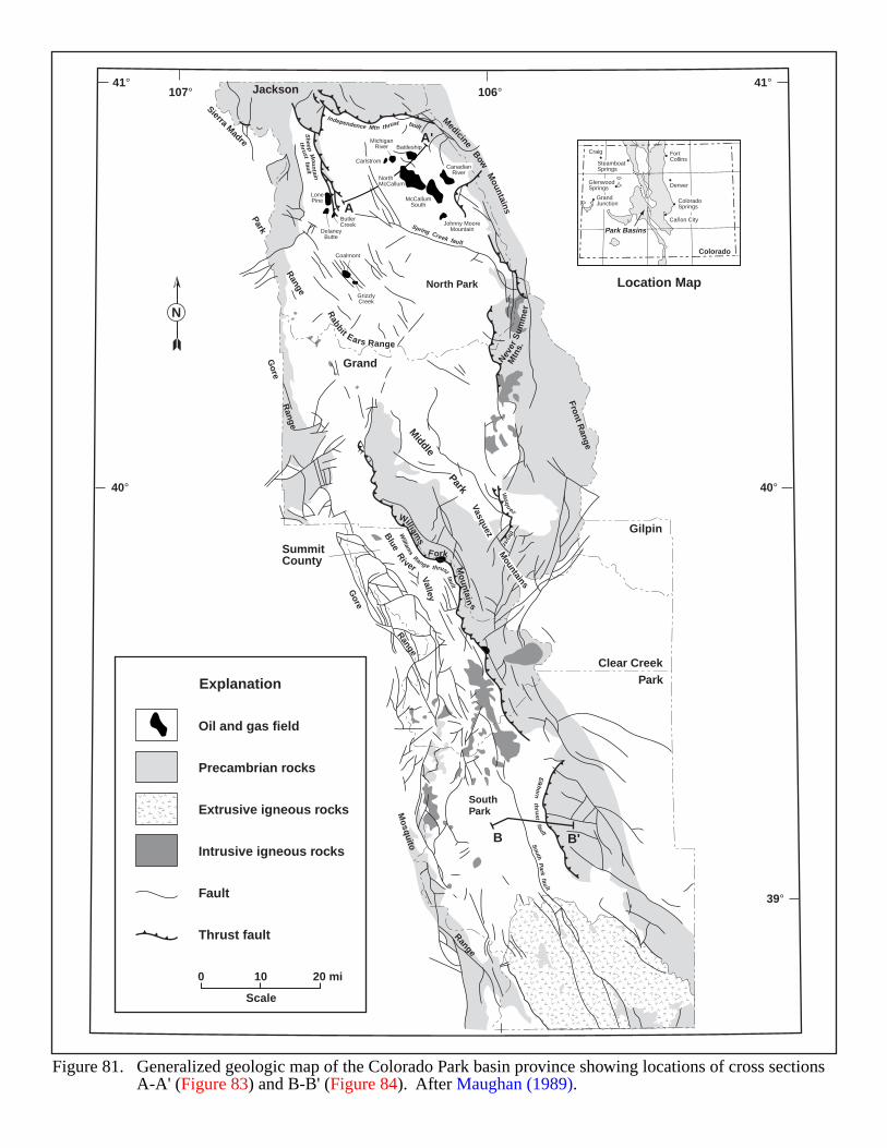
Figure 81. Generalized geologic map of the Colorado Park basin province showing locations of cross sectionsA-A' (Figure 83) and B-B' (Figure 84). After Maughan (1989).
0 10 20 mi
Scale
41°107° 106°
41°
40°40°
39°
N
Oil and gas field
Precambrian rocks
Extrusive igneous rocks
Intrusive igneous rocks
Fault
Explanation
Denver
ColoradoSprings
Cañon City
FortCollins
Colorado
Craig
SteamboatSprings
GlenwoodSprings
GrandJunction
Park Basins
Location Map
Thrust fault
Park Range
Rabbit Ears Range
Sierra Madre
Gore R
ange
MedicineBow
Mountains
Never
Sum
mer
Mtn
s.
VasquezM
ountains
Williams
F ork
Mo
untain
s
egna
R
ero
G
Mosquito
Range
Jackson
Grand
Gilpin
Clear CreekPark
SummitCounty
North Park
Middle Park
SouthPark
Independence Mtn thrust fault
Sh
eepM
oun
tain
thrust
fault
Spring Creek fault
BattleshipMichigan
River
Carlstrom
NorthMcCallum
McCallumSouth
CanadianRiver
Johnny MooreMountain
LonePine
DelaneyButte
ButlerCreek
Coalmont
GrizzlyCreek
Vasqu
ezthrust
William
s
Range thrustfault
Blue
River
Valley
Elkhorn
thrust
fault
South
Park
fault
B B'
A
A'
Front Range
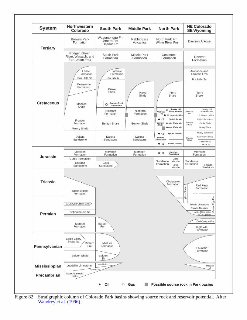
Figure 82. Stratigraphic column of Colorado Park basins showing source rock and reservoir potential. AfterWandrey et al. (1996).
Oil Gas Possible source rock in Park basins
NorthwesternColorado
Browns ParkFormation
South ParkFormation
LanceFormation
Fox Hills Ss
MesaverdeFormation
MancosShale
FrontierFormation
MorrisonFormation
State BridgeFormation
Eagle ValleyEvaporite
MaroonFormation
MinturnFm
MinturnFormation
MaroonFm
MorrisonFormation
MorrisonFormation
MorrisonFormation
SundanceFormation
ChugwaterFormation Red Peak
Formation
InglesideFormation
FountainFormation
MadisonLs
SundanceFormation
UpperMember
LowerMember
Glendo Member
Owl Canyon Fm
Forelle Limestone
Lyons Ss
MinnekahtaOpeche
EntradaSandstone
Lyki
ns S
hale
Goo
se E
gg F
m
MorrisonFormation
DakotaSandstone
EntradaSandstone
GaroSandstone
DakotaSandstone
DakotaSandstone
NiobraraFormation
NiobraraFormation
Benton Shale Benton Shale
Mowry Shale
Belden Shale BeldenSh
Curtis Formation
Schoolhouse Ss
Leadville Limestone
lower Paleozoicrocks
Leadville Ls
S. Canyon Creek Dolo
Gilman Ss
PierreShale Pierre
ShalePierreShale
PierreShale
Apache CreekSandstone
Smoky HillShale Member
Codell Ss Mbr
Middle Shaly Mbr
Mowry Shale Mbr
Smoky HillShale Member
Ft. Hayes Ls Mbr Ft. Hayes Ls Mbr
NiobraraFm
BentonShale
Codell Sandstone
Carlile Shale
Mowry Shale
BentonGroup
NiobraraFm
Fox Hills Ss Fox Hills Ss
LaramieFormation
Arapahoe andLaramie Fms
Middle ParkFormation
CoalmontFormation Denver
Formation
Rabbit EarsVolcanics Dawson Arkose
North Park FmWhite River Fm
Wagontongue FmAntero FmBalfour Fm
Bridger, GreenRiver, Wasatch, and
Fort Union Fms
NE ColoradoSE WyomingSouth Park Middle Park North Park
Upper Member
Lower Member
DakotaSandstone
Muddy Sandstone
Skull Creek Shale
Fall River SsLakota Ss
DakotaGroup
System
Tertiary
Cretaceous
Jurassic
Triassic
Permian
Pennsylvanian
Mississippian
Precambrian
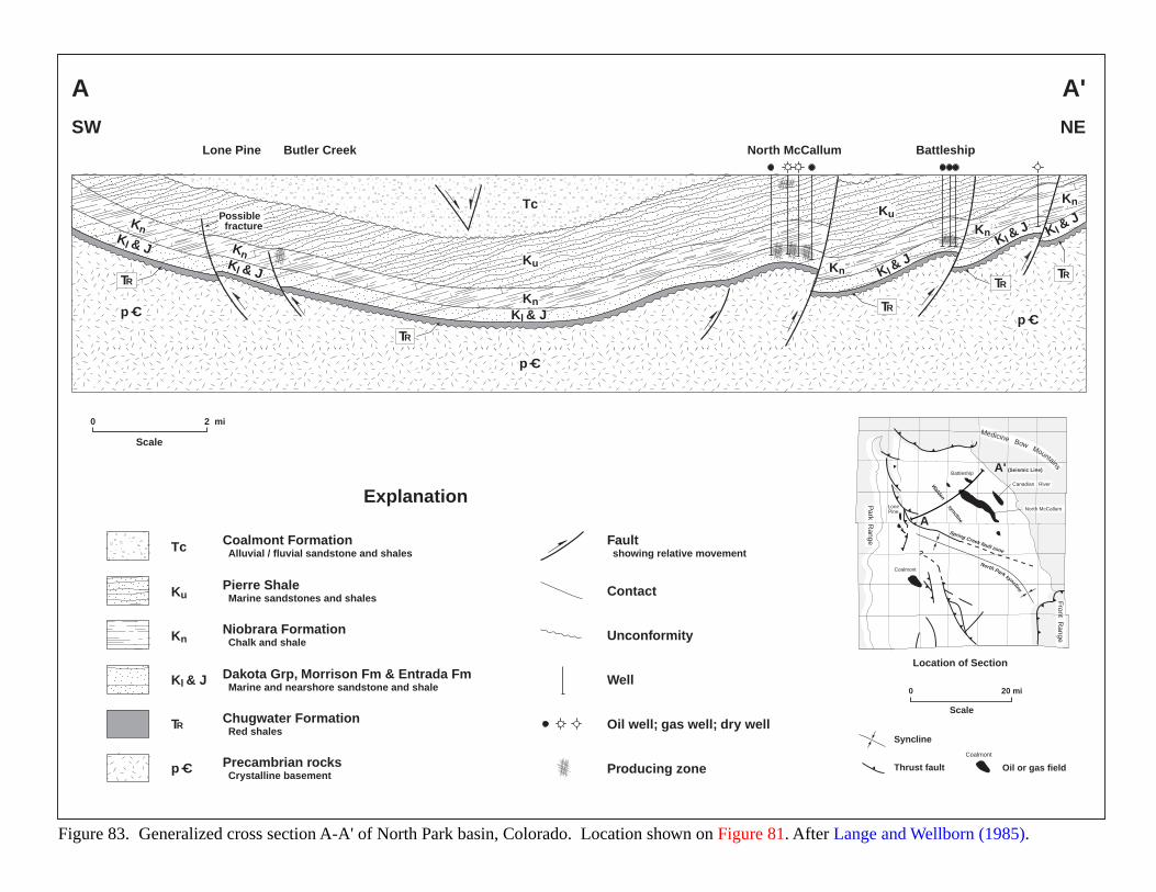
Coalmont Formation Alluvial / fluvial sandstone and shales
Pierre Shale Marine sandstones and shales
Niobrara Formation Chalk and shale
Dakota Grp, Morrison Fm & Entrada Fm Marine and nearshore sandstone and shale
Chugwater Formation Red shales
Precambrian rocks Crystalline basement
Fault showing relative movement
Unconformity
Well
Oil well; gas well; dry well
Producing zone
Contact
Figure 83. Generalized cross section A-A' of North Park basin, Colorado. Location shown on Figure 81. After Lange and Wellborn (1985).
Explanation
0 2 mi
Scale
Tc
Ku
Kn
Kl & J
TR
p C
A
A' (Seismic Line)
Spring Creek fault zone?
North Park syncline
Walden syncline
Battleship
LonePine
Coalmont
Canadian River
North McCallum
Medicine Bow Mountains
Park R
ange
Front Range
Location of Section
Thrust fault Oil or gas field
Syncline
Coalmont
0 20 mi
Scale
SW NE
A A'
Lone Pine Butler Creek North McCallum Battleship
p C
p Cp C
Tc
Ku
Ku
Kn
Kn
Kn
Kn
Kn
Kn
Kl & J
Kl & JKl & J Kl &
JKl &
J Kl & J
TR
TR
TR
TRTR
Possible fracture
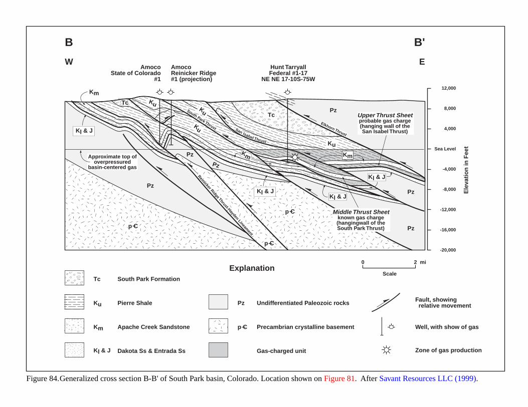
Figure 84.Generalized cross section B-B' of South Park basin, Colorado. Location shown on Figure 81. After Savant Resources LLC (1999).
South Park Formation
Pierre Shale
Apache Creek Sandstone
Dakota Ss & Entrada Ss
Precambrian crystalline basement
Undifferentiated Paleozoic rocksPz
Gas-charged unit
Fault, showing relative movement
Well, with show of gas
Zone of gas production
Explanation0 2 mi
Scale
p C
Tc
Ku
Km
Kl & J
W
B
E
B'
12,000
8,000
4,000
Sea Level
-4,000
-8,000
-12,000
-16,000
-20,000
Ele
vati
on
in F
eet
South Park ThrustElkhorn Thrust
Reinicker Ridge Thrust-Hayden Lineament
San Isabel Thrust
Pz
Pz
Pz
Pz
Pz
Pz
p C
p C
p C
Tc
Tc
Ku
Ku
Ku
Ku
Km
Kl & J
Kl & J
Kl & J
Kl & J
Km Km
AmocoState of Colorado
#1
AmocoReinicker Ridge#1 (projection)
Hunt TarryallFederal #1-17
NE NE 17-10S-75W
Approximate top ofoverpressured
basin-centered gas
Middle Thrust Sheetknown gas charge(hangingwall of theSouth Park Thrust)
Upper Thrust Sheetprobable gas charge(hanging wall of theSan Isabel Thrust)
187
PERMIAN BASIN (ABO FORMATION)
GEOLOGIC SETTING
The Permian Basin of west Texas and eastern New Mexico covers about 76,250 square miles of the southwestpart of the North American mid-continent craton (Frenzel et al., 1988). Figure 85 shows the location and generalizedstructure of the area. This part of the craton remained exposed until Late Cambrian, when marine transgressionformed the Tobosa Basin and filled it mainly with carbonate and fine-grained clastic sediments. The Tobosa Basinwas relatively stable until the Late Mississippian, when structural deformation began forming the Matador Uplift,Central Basin Platform, and Diablo Platform. By the Early Pennsylvanian, the Tobosa Basin had broken up into themain elements making up the present day Permian Basin: Northwest Shelf, Delaware Basin, Central Basin Platform,Midland Basin, Val Verde Basin, and Eastern Shelf (Frenzel et al., 1988). Pennsylvanian strata of the basin consistsof marine and paralic sandstones, shales, and carbonates.
A final structural pulse deformed the Central Basin and Diablo Platforms in the Early Permian (Wolfcampian).Permian sedimentation filled the Delaware and Midland Basins with deep-water carbonates and shales, basin-marginreef carbonates, evaporites, and red-bed sequences. Permian strata contain most of the hydrocarbon reserves within thebasin. Since the Triassic, the Permian Basin has remained tectonically stable.
HYDROCARBON PRODUCTION
Figure 86 shows stratigraphic columns for various basins and platforms in the area. Originally assigned to aPermian (lower Leonardian) red-bed sequence in the Northwest Shelf, the Abo Formation has also been applied todolomitized carbonates along the northern margins of the Delaware Basin and the Central Basin Platform. The age-equivalent strata in the Central Basin Platform and in the Delaware and Midland Basins have produced hydrocarbonshistorically. In the Midland Basin, Abo age-equivalent and mature Spraberry Trend covers hundreds of square milesand has produced over 1,388 BCF of gas plus associated condensate (Bebout and Garret, 1989).
Production from the Abo Formation derives from two plays: platform carbonates and fluvial/deltaic sandstones(Figure 87). Most platform-carbonate production comes from the Abo reef trend (Figure 85). The reef reservoirs arestratigraphic traps with clean, white-tan-gray, fine to coarsely crystalline dolostones. Porosity is secondary,consisting of vugs, vertical fractures and intercrystalline pores. Cumulative production from the reef reservoirs was456 BCFG as of December 31, 1990. A smaller shelf sub-play also exists, and consists of dolomitized back-reefsediments having irregularly distributed porosity and permeability. Traps are low-relief anticlines that have produced227 BCFG through 1990.
The Abo fluvial/deltaic sandstone is a tight gas play on the Northwest Shelf. Production comes from lenticular,red, very fine to fine grained, silty, arkosic arenites (Broadhead, 1993a, c). A clay-hematite matrix has reduced theprimary porosity. Deep-seated faults that tap into older Paleozoic source beds have charged these reservoirs. The threemain fields have produced 273 BCFG from stratigraphic traps as of December 31, 1990.
188
EVIDENCE FOR BASIN-CENTERED GAS
Neither of the two Abo plays are basin-centered. The carbonate play rings the Permian basin margin, and thesandstone play is confined to the northern Northwest Shelf area (Figure 87). However, both plays have anomalouspressure gradients associated with them. The fluvial/deltaic sandstones show a significant underpressure to producingfields (Broadhead, 1993c). The single shelf-carbonate sub-play field has a normal pressure gradient. Abo reefcarbonates display a trend: near-normal pressure gradients exist in the south and become underpressured northward(Broadhead, 1993b). Similar south-to-north underpressure gradients are visible in data from the underlying WolfcampFormation, overlying Yeso Formation, and basinal-equivalent Bone Spring Formation (Broadhead, 1993a):
Unit or Lithology Depth (ft) Pressure Gradient (psi/ft) Temperature (°F)
Yeso Fm.................................5,000 – 7,030..................0.263 – 0.495.........................105 – 122
Bone Spring Fm.......................5,480 – 9,700..................0.343 – 0.428.........................128 – 180
Abo sandstones.........................2,830 – 4,180..................0.295 – 0.387.........................101 – 114
Abo reef carbonates....................6,020 – 8,650..................0.286 – 0.430.........................109 – 140
Wolfcamp Fm.........................8,020 – 13,250.................0.354 – 0.843.........................129 – 193
KEY ACCUMULATION PARAMETERS
Identification Southwestern U.S., west Texas and eastern New Mexico. Lower Permian Abo Formation
Geologic Characterization of Accumulation:
a. Source/reservoir Source intervals: poorly documented and appear to be largely speculative in the literature. Major sources are thought to occur in Permian basinal shales and carbonates (Wolfcamp and Bone Springs), Permian shelf shales
and low energy carbonates (Wolfcamp and Abo/Wichita-Albany), Pennsylvanian limestones and shales, and Upper Devonian (Woodford)– Mississippian (Barnett) shales (Broadhead, 1993a; Hanson et al., 1991).
Reservoir intervals: Abo platform carbonates are mainly dolomite, Abo fluvial/deltaics are mainly red-bed sandstones.
b. Total Organic Carbons (TOCs)
1-3% for Midland Basin Spraberry black shales (Ramondetta, 1982)
c. Thermal maturity Kerogen Type: algal and amorphous for Midland Basin Spraberry black shales (Ramondetta, 1982)
d. Oil or gas prone Both oil and gas prone.
e. Overall basin maturity Mature
f. Age and lithologies Permian Abo platform carbonates-lower Leonardian, Permian Abo fluvial/deltaic sandstones-lower Leonardian (Broadhead, 1993b, c).
g. Rock extent/quality Source rock occurs basin wide, Abo platform carbonate reservoir rock has a distribution which follows the margin of the Delaware and Midland Basins and the Central Basin Platform, Abo fluvial/deltaic sandstones are found
north of the barrier reef trend on the Northwest Shelf.h. Potential reservoirs
i. Major traps/seals Abo platform carbonates: anticline/dome and lateral changes in porosity and/or permeability because of changes in depositional environment; Abo fluvial/deltaic sandstones: stratigraphic trap, but poorly understood (Broadhead, 1993b, c).
j. Petroleum generation/migration models
Barber (1979)
k. Depth ranges Abo platform carbonates, 6020-8650 ft; Abo fluvial/deltaic sandstones, 2830-4180 ft (Broadhead, 1993b, c)
l. Pressure gradients 0.263 to 0.843 psi/ft.
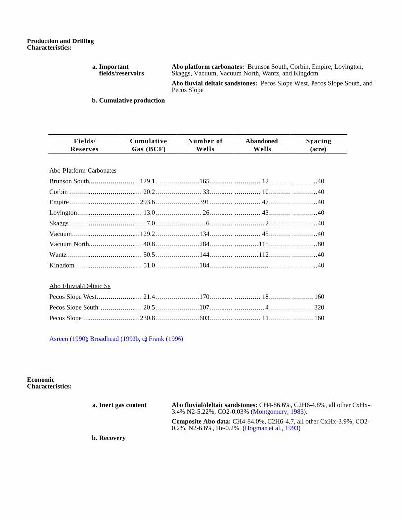
Production and Drilling Characteristics:
a. Important fields/reservoirs
Abo platform carbonates: Brunson South, Corbin, Empire, Lovington, Skaggs, Vacuum, Vacuum North, Wantz, and Kingdom
Abo fluvial deltaic sandstones: Pecos Slope West, Pecos Slope South, and Pecos Slope
b. Cumulative production
Economic Characteristics:
a. Inert gas content Abo fluvial/deltaic sandstones: CH4-86.6%, C2H6-4.8%, all other CxHx-3.4% N2-5.22%, CO2-0.03% (Montgomery, 1983).
Composite Abo data: CH4-84.0%, C2H6-4.7, all other CxHx-3.9%, CO2-0.2%, N2-6.6%, He-0.2% (Hogman et al., 1993)
b. Recovery
Fields/Reserves
CumulativeGas (BCF)
Number ofWells
AbandonedWells
Spacing(acre)
Abo Platform Carbonates
Brunson South..........................129.1 ......................165............ ............. 12........... .............40
Corbin ..................................... 20.2 ....................... 33............ ............. 10........... .............40
Empire....................................293.6 ......................391............ ............. 47........... .............40
Lovington................................. 13.0 ....................... 26............ ............. 43........... .............40
Skaggs ....................................... 7.0 ......................... 6............ ............... 2........... .............40
Vacuum...................................129.2 ......................134............ ............. 45........... .............40
Vacuum North........................... 40.8 ......................284............ ............115........... .............80
Wantz...................................... 50.5 ......................144............ ............112........... .............40
Kingdom.................................. 51.0 ......................184............ ............................ .............40
Abo Fluvial/Deltaic Ss
Pecos Slope West....................... 21.4 ......................170............ ............. 18........... ........... 160
Pecos Slope South ..................... 20.5 ......................107............ ............... 4........... ........... 320
Pecos Slope .............................230.8 ......................603............ ............. 11........... ........... 160
Asreen (1990); Broadhead (1993b, c); Frank (1996)

c. Pipeline infrastructure Very good. There are numerous gas lines in the basin.
d. Exploration maturity relative to other basins
Mature
e. Sediment consolidation Good to moderate consolidation.
f. Porosity/completion problems
Abo fluvial/deltaic sandstones are classified as tight gas. These reservoirs require acidization and artificial fracturing. Average in-situ permeability is 0.0067 md; average porosity is 12-14% with 9% necessary
for economic production. Production operates on a pressure depletion/gas expansion drive. Abo platform carbonates have an irregular distribution of secondary porosity, averaging 6-14% but ranging from 1.5-18.3%.
Permeability also has an irregular distribution resulting in poor fluid communication within the reservoir. Permeability averages 1.5-25 md but ranges from 0.1-1,970 md. This play operates on a primary gas-cap
expansion drive augmented by secondary gas-cap growth due to pressure dissolution (Broadhead, 1993b). In the Empire field some component of water drive may be operating (LeMay, 1972).
g. Permeability 0.0067 md
h. Porosity 12 to 14%
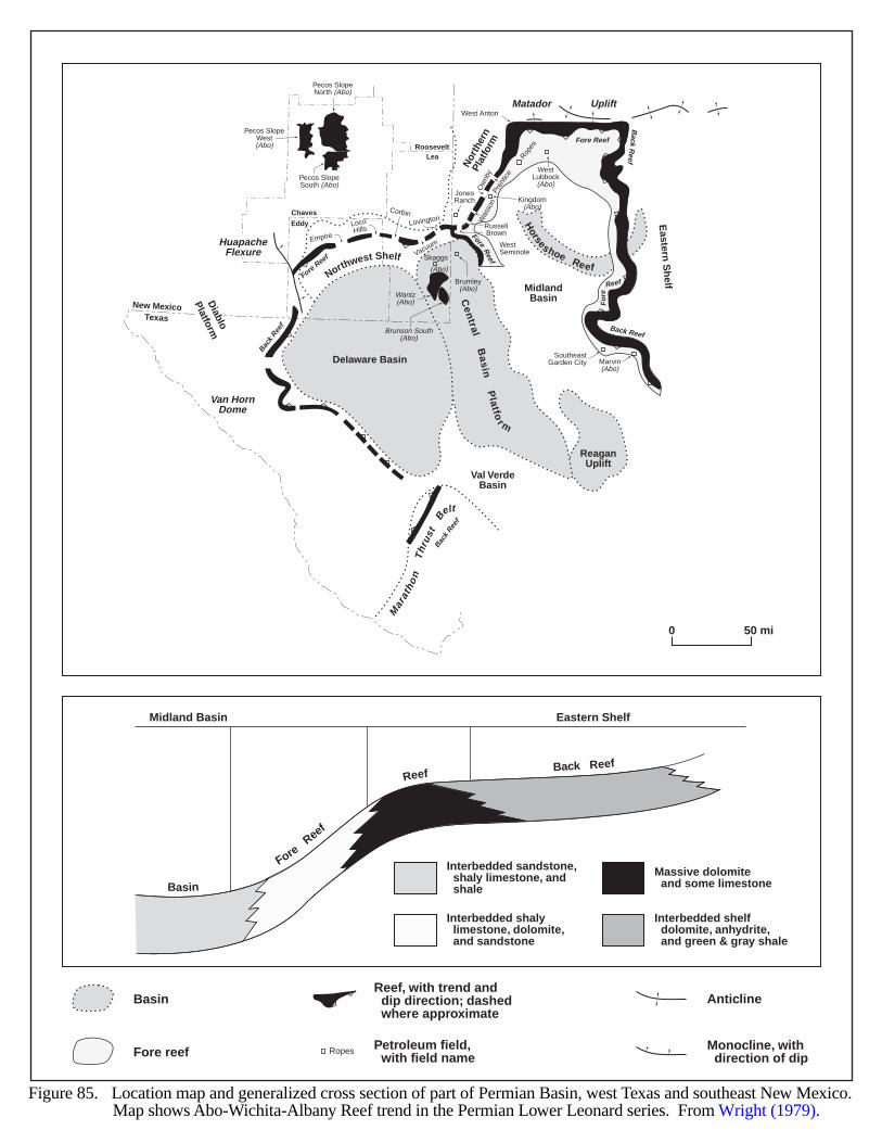
Delaware Basin
MidlandBasin
Eastern
Sh
elf
Horseshoe Reef
Val VerdeBasin
New MexicoTexas
Eddy
Chaves
LeaRoosevelt
Matador Uplift
HuapacheFlexure
ReaganUplift
Van HornDome
Nor
ther
nPl
atfo
rm
Mar
atho
nT
hrus
t
Belt
Cen
tralB
asin
Platfo
r m
Fore Reef
Fore Reef
Back Ree
f Back Reef
Back R
eef
Back Ree
f
Fore
Fo
re
Reef
Reef
Basin
ForeReef
Reef Back Reef
Midland Basin Eastern Shelf
Diablo
Platform
Empire
Corbin
LocoHills
Lovington
Vacuum WestSeminole
SoutheastGarden City
Brown
Pren
tice
Was
son
JonesRanch
Skaggs
(Abo)
Ropes
West Anton
WestLubbock
(Abo)
Marvin(Abo)
Kingdom(Abo)
Ow
nby
Northwest Shelf
Russell
Brumley(Abo)
Wantz(Abo)
Brunson South(Abo)
Pecos SlopeWest(Abo)
Pecos SlopeNorth (Abo)
Pecos SlopeSouth (Abo)
0 50 mi
BasinReef, with trend and dip direction; dashed where approximate
Fore reef Petroleum field, with field name
Anticline
Interbedded sandstone, shaly limestone, and shale
Interbedded shaly limestone, dolomite, and sandstone
Massive dolomite and some limestone
Interbedded shelf dolomite, anhydrite, and green & gray shale
Monocline, with direction of dip
Ropes
Figure 85. Location map and generalized cross section of part of Permian Basin, west Texas and southeast New Mexico. Map shows Abo-Wichita-Albany Reef trend in the Permian Lower Leonard series. From Wright (1979).
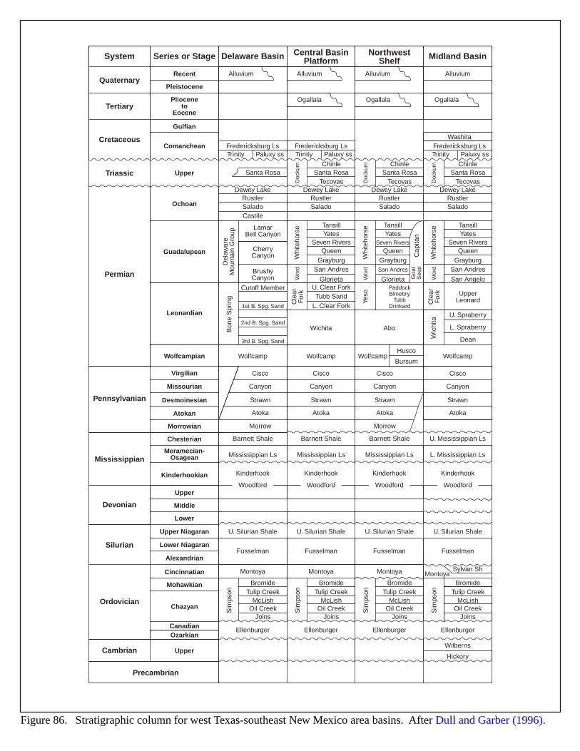
System
QuaternaryRecent
Pleistocene
Gulfian
Upper
Ochoan
Guadalupean
Leonardian
Wolfcampian
Virgilian
Missourian
Desmoinesian
Comanchean Fredericksburg Ls
RustlerSalado
RustlerSalado
Wichita Abo
Husco
Bursum
TansillYates
Seven RiversQueen
GrayburgSan Andres
GlorietaU. Clear ForkTubb Sand
L. Clear Fork
TansillYates
Seven Rivers
QueenGrayburgSan Andres
GlorietaPaddockBlinebry
TubbDrinkard
TansillYates
Seven RiversQueen
GrayburgSan Andres
San Angelo
UpperLeonard
RustlerSalado
RustlerSalado
Castile
Wolfcamp
Cisco
Canyon
Strawn
Atoka
Morrow
Cisco
Canyon
Strawn
Atoka
Cisco
Canyon
Strawn
Atoka
Morrow
Cisco
Canyon
Strawn
Atoka
Wolfcamp Wolfcamp Wolfcamp
Cutoff Member
1st B. Spg. Sand
2nd B. Spg. Sand
3rd B. Spg. Sand
LamarBell Canyon
CherryCanyon
BrushyCanyon
Dewey Lake
Del
awar
eM
ount
ain
Gro
upB
one
Spr
ing
Whi
teho
rse
Wor
dD
ocku
mC
lear
For
k
Cle
arF
ork
Whi
teho
rse
Wor
dYe
so
Whi
teho
rse
Wor
d
Goa
tS
eep
Cap
itan
U. Spraberry
L. Spraberry
DeanWic
hita
Dewey Lake Dewey Lake Dewey Lake
Fredericksburg Ls Fredericksburg LsWashita
Santa Rosa
Alluvium Alluvium
Ogallala Ogallala Ogallala
Alluvium Alluvium
Santa RosaTecovas D
ocku
m
Santa RosaChinle
Tecovas Doc
kum
Santa RosaChinle
Tecovas
Plioceneto
EoceneTertiary
Cretaceous
Triassic
Permian
Pennsylvanian
Series or Stage Delaware Basin Central BasinPlatform
NorthwestShelf Midland Basin
Chinle
Trinity Paluxy ss Trinity Paluxy ss Trinity Paluxy ss
Atokan
Morrowian
Chesterian
Kinderhookian
Upper
Upper
Middle
Lower
Upper Niagaran
Lower Niagaran
Alexandrian
Cincinnatian
Mohawkian
Chazyan
CanadianOzarkian
Meramecian-Osagean
Barnett Shale Barnett Shale Barnett Shale U. Mississippian Ls
L. Mississippian LsMississippian LsMississippian LsMississippian Ls
Kinderhook Kinderhook
U. Silurian Shale U. Silurian Shale U. Silurian ShaleU. Silurian Shale
Fusselman
Montoya
Ellenburger
BromideTulip Creek
McLishOil Creek
Joins
Fusselman Fusselman Fusselman
Kinderhook Kinderhook
Sim
pson
Montoya
Ellenburger
BromideTulip Creek
McLishOil Creek
Joins
Sim
pson
Montoya
Ellenburger
BromideTulip Creek
McLishOil Creek
Joins
Sim
pson
MontoyaSylvan Sh
Ellenburger
Wilberns
Hickory
BromideTulip Creek
McLishOil Creek
Joins
Sim
pson
Mississippian
Devonian
Silurian
Ordovician
Cambrian
Precambrian
WoodfordWoodfordWoodfordWoodford
Figure 86. Stratigraphic column for west Texas-southeast New Mexico area basins. After Dull and Garber (1996).
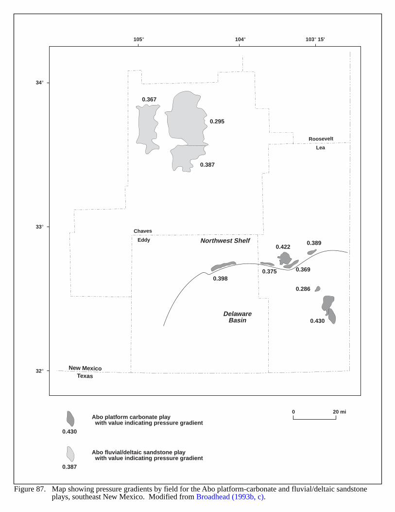
New MexicoTexas
Eddy
Chaves
Lea
Roosevelt
105° 104° 103° 15'
34°
33°
32°
0.367
0.295
0.387
0.3980.375 0.369
0.286
0.430
0.3890.422
DelawareBasin
Northwest Shelf
0 20 mi
0.430
Abo platform carbonate play with value indicating pressure gradient
0.387
Abo fluvial/deltaic sandstone play with value indicating pressure gradient
Figure 87. Map showing pressure gradients by field for the Abo platform-carbonate and fluvial/deltaic sandstone plays, southeast New Mexico. Modified from Broadhead (1993b, c).
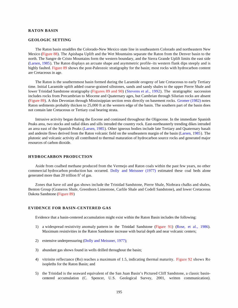
195
RATON BASIN
GEOLOGIC SETTING
The Raton basin straddles the Colorado-New Mexico state line in southeastern Colorado and northeastern NewMexico (Figure 88). The Apishapa Uplift and the Wet Mountains separate the Raton from the Denver basin to thenorth. The Sangre de Cristo Mountains form the western boundary, and the Sierra Grande Uplift limits the east side(Larsen, 1985). The Raton displays an arcuate shape and asymmetric profile–its western flank dips steeply and ishighly faulted. Figure 89 shows the post-Paleozoic stratigraphy for the basin; most rocks with hydrocarbon contentare Cretaceous in age.
The Raton is the southernmost basin formed during the Laramide orogeny of late Cretaceous to early Tertiarytime. Initial Laramide uplift added coarse-grained siltstones, sands and sandy shales to the upper Pierre Shale andlower Trinidad Sandstone stratigraphy (Figures 89 and 90) (Stevens et al., 1992). The stratigraphic successionincludes rocks from Precambrian to Miocene and Quaternary ages, but Cambrian through Silurian rocks are absent(Figure 89). A thin Devonian through Mississippian section rests directly on basement rocks. Gromer (1982) notesRaton sediments probably thicken to 25,000 ft at the western edge of the basin. The southern part of the basin doesnot contain late Cretaceous or Tertiary coal bearing strata.
Intrusive activity began during the Eocene and continued throughout the Oligocene. In the immediate SpanishPeaks area, two stocks and radial dikes and sills intruded the country rock. East-northeasterly trending dikes intrudedan area east of the Spanish Peaks (Larsen, 1985). Other igneous bodies include late Tertiary and Quaternary basaltand andesite flows derived from the Raton volcanic field on the southeastern margin of the basin (Larsen, 1985). Theplutonic and volcanic activity all contributed to thermal maturation of hydrocarbon source rocks and generated majorresources of carbon dioxide.
HYDROCARBON PRODUCTION
Aside from coalbed methane produced from the Vermejo and Raton coals within the past few years, no othercommercial hydrocarbon production has occurred. Dolly and Meissner (1977) estimated these coal beds alonegenerated more than 20 trillion ft3 of gas.
Zones that have oil and gas shows include the Trinidad Sandstone, Pierre Shale, Niobrara chalks and shales,Benton Group (Graneros Shale, Greenhorn Limestone, Carlile Shale and Codell Sandstone), and lower CretaceousDakota Sandstone (Figure 89)
EVIDENCE FOR BASIN-CENTERED GAS
Evidence that a basin-centered accumulation might exist within the Raton Basin includes the following:
1) a widespread resistivity anomaly pattern in the Trinidad Sandstone (Figure 91) (Rose, et al., 1986).Maximum resistivities in the Raton Sandstone increase with burial depth and near volcanic centers;
2) extensive underpressuring (Dolly and Meissner, 1977);
3) abundant gas shows found in wells drilled throughout the basin;
4) vitrinite reflectance (Ro) reaches a maximum of 1.5, indicating thermal maturity. Figure 92 shows Roisopleths for the Raton Basin; and
5) the Trinidad is the seaward equivalent of the San Juan Basin’s Pictured Cliff Sandstone, a classic basin-centered accumulation (C. Spencer, U.S. Geological Survey, 2001, written communication).
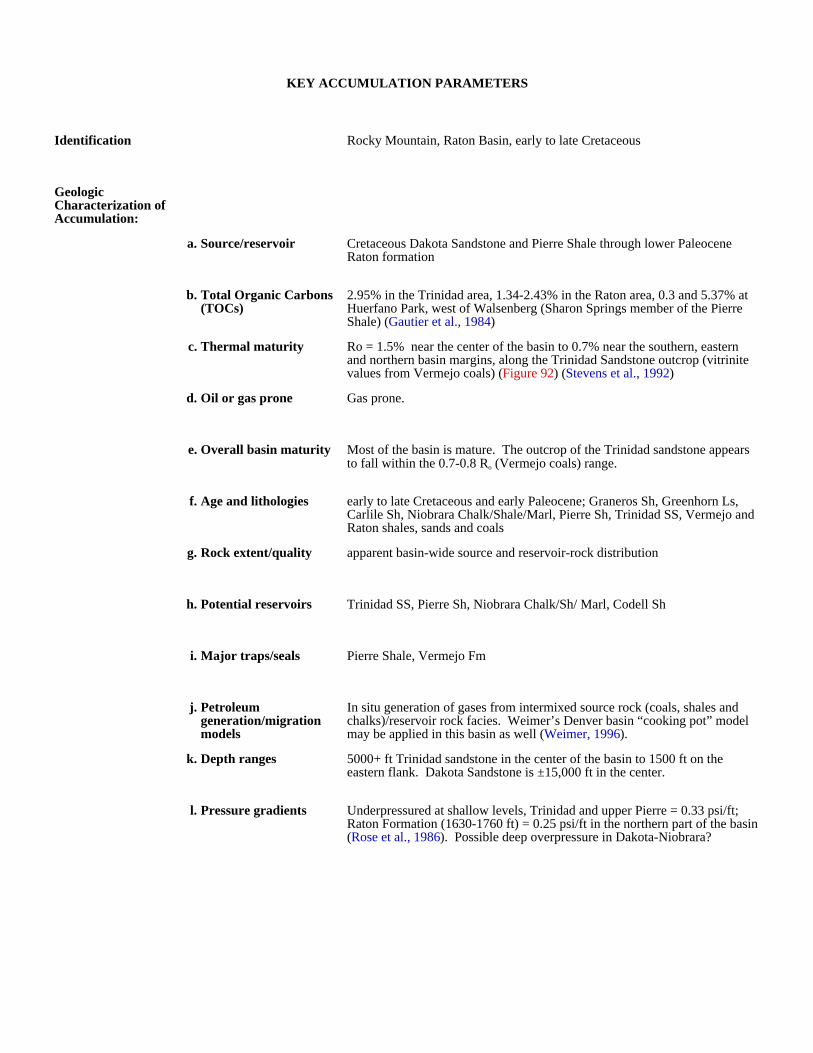
KEY ACCUMULATION PARAMETERS
Identification Rocky Mountain, Raton Basin, early to late Cretaceous
Geologic Characterization of Accumulation:
a. Source/reservoir Cretaceous Dakota Sandstone and Pierre Shale through lower Paleocene Raton formation
b. Total Organic Carbons (TOCs)
2.95% in the Trinidad area, 1.34-2.43% in the Raton area, 0.3 and 5.37% at Huerfano Park, west of Walsenberg (Sharon Springs member of the Pierre Shale) (Gautier et al., 1984)
c. Thermal maturity Ro = 1.5% near the center of the basin to 0.7% near the southern, eastern and northern basin margins, along the Trinidad Sandstone outcrop (vitrinite values from Vermejo coals) (Figure 92) (Stevens et al., 1992)
d. Oil or gas prone Gas prone.
e. Overall basin maturity Most of the basin is mature. The outcrop of the Trinidad sandstone appears to fall within the 0.7-0.8 Ro (Vermejo coals) range.
f. Age and lithologies early to late Cretaceous and early Paleocene; Graneros Sh, Greenhorn Ls, Carlile Sh, Niobrara Chalk/Shale/Marl, Pierre Sh, Trinidad SS, Vermejo and Raton shales, sands and coals
g. Rock extent/quality apparent basin-wide source and reservoir-rock distribution
h. Potential reservoirs Trinidad SS, Pierre Sh, Niobrara Chalk/Sh/ Marl, Codell Sh
i. Major traps/seals Pierre Shale, Vermejo Fm
j. Petroleum generation/migration models
In situ generation of gases from intermixed source rock (coals, shales and chalks)/reservoir rock facies. Weimer’s Denver basin “cooking pot” model may be applied in this basin as well (Weimer, 1996).
k. Depth ranges 5000+ ft Trinidad sandstone in the center of the basin to 1500 ft on the eastern flank. Dakota Sandstone is ±15,000 ft in the center.
l. Pressure gradients Underpressured at shallow levels, Trinidad and upper Pierre = 0.33 psi/ft; Raton Formation (1630-1760 ft) = 0.25 psi/ft in the northern part of the basin (Rose et al., 1986). Possible deep overpressure in Dakota-Niobrara?
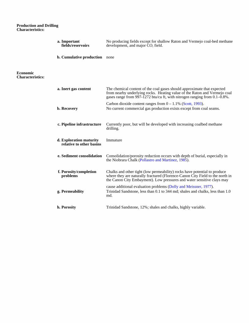
Production and Drilling Characteristics:
a. Important fields/reservoirs
No producing fields except for shallow Raton and Vermejo coal-bed methane development, and major CO2 field.
b. Cumulative production none
Economic Characteristics:
a. Inert gas content The chemical content of the coal gases should approximate that expected from nearby underlying rocks. Heating value of the Raton and Vermejo coal gases range from 997-1272 btu/cu ft, with nitrogen ranging from 0.1–0.8%.
Carbon dioxide content ranges from 0 – 1.1% (Scott, 1993).b. Recovery No current commercial gas production exists except from coal seams.
c. Pipeline infrastructure Currently poor, but will be developed with increasing coalbed methane drilling.
d. Exploration maturity relative to other basins
Immature
e. Sediment consolidation Consolidation/porosity reduction occurs with depth of burial, especially in the Niobrara Chalk (Pollastro and Martinez, 1985).
f. Porosity/completion problems
Chalks and other tight (low permeability) rocks have potential to produce where they are naturally fractured (Florence-Canon City Field to the north in the Canon City Embayment). Low pressures and water sensitive clays may
cause additional evaluation problems (Dolly and Meissner, 1977).g. Permeability Trinidad Sandstone, less than 0.1 to 344 md; shales and chalks, less than 1.0
md.
h. Porosity Trinidad Sandstone, 12%; shales and chalks, highly variable.
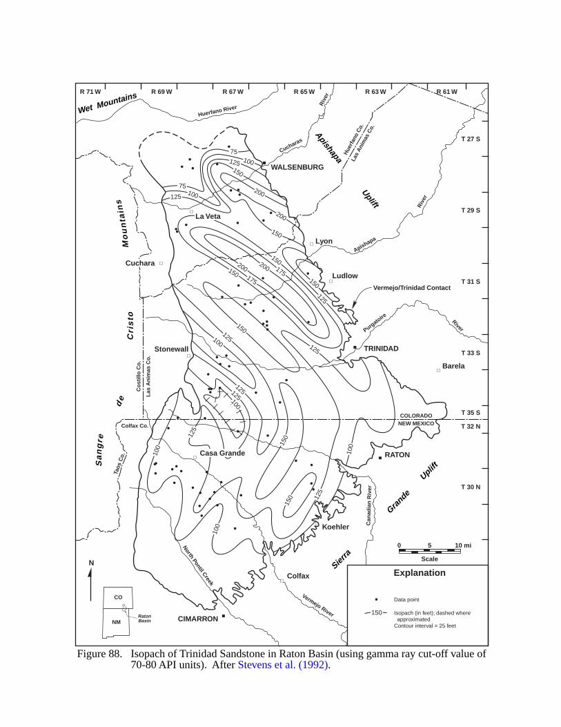
|
||
|
||
|||
||
|
75
75100
150
200
200
200200175
175
150
150
150
125
125
125125100
100
100
100
125
125
150
150
100 125
150
150
125
125100
Vermejo River
North Pontil Creek
Can
adia
n R
iver
Purgatoire River
Apishapa
Riv
er
Cucharas
Riv
er
Huerfano River
TRINIDAD
RATON
Koehler
Barela
Ludlow
Lyon
WALSENBURG
Cuchara
Stonewall
Casa Grande
Colfax
CIMARRON
La Veta
COLORADONEW MEXICO
Co
still
o C
o.
Las
An
imas
Co
.
Las
Ani
mas
Co.
Hue
rfan
o C
o.
Colfax Co.
Taos
Co.
Apishapa Uplift
Wet Mountains
Sierra
Grande
U
pliftS
an
gre
de
Cri
sto
Mo
un
tain
s
Vermejo/Trinidad Contact
R 71 W R 69 W R 67 W R 65 W R 63 W R 61 W
T 27 S
T 29 S
T 31 S
T 33 S
T 35 S
T 32 N
T 30 N
N
0 5
Scale
10 mi
Figure 88. Isopach of Trinidad Sandstone in Raton Basin (using gamma ray cut-off value of 70-80 API units). After Stevens et al. (1992).
Data point
Isopach (in feet); dashed where approximatedContour interval = 25 feet
Explanation
150
CO
NMRatonBasin
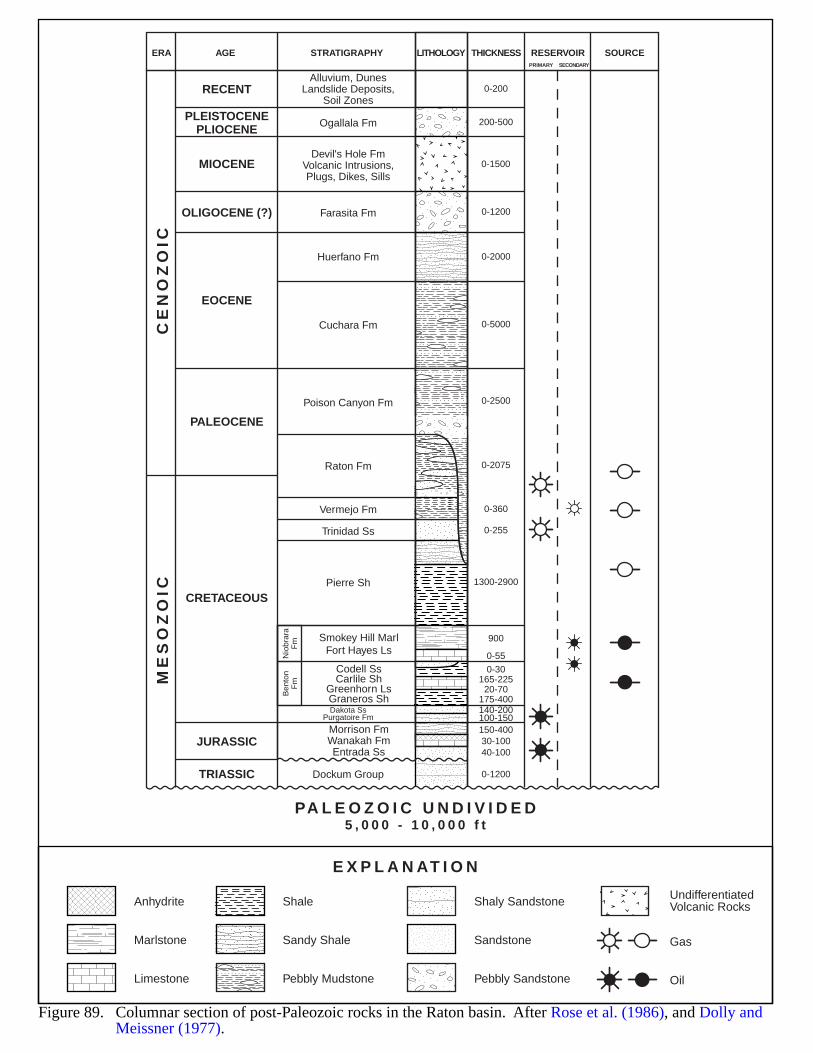
Figure 89. Columnar section of post-Paleozoic rocks in the Raton basin. After Rose et al. (1986), and Dolly and Meissner (1977).
E X P L A N AT I O N
Anhydrite
Marlstone
Limestone
Shale
Sandy Shale
Pebbly Mudstone
Shaly Sandstone UndifferentiatedVolcanic Rocks
Sandstone Gas
OilPebbly Sandstone
CE
NO
ZO
IC
PA L E O Z O I C U N D I V I D E D5 , 0 0 0 - 1 0 , 0 0 0 f t
ME
SO
ZO
IC
RECENTAlluvium, Dunes
Landslide Deposits,Soil Zones
Ogallala Fm 200-500
0-1500
0-1200
0-2000
0-5000
0-2500
0-2075
0-360
0-255
1300-2900
900
0-55
0-1200
0-30165-22520-70
175-400
150-40030-10040-100
140-200100-150
0-200
ERA AGE STRATIGRAPHY LITHOLOGY THICKNESS RESERVOIR SOURCEPRIMARY SECONDARY
Devil's Hole FmVolcanic Intrusions,Plugs, Dikes, Sills
Farasita Fm
Huerfano Fm
Cuchara Fm
Poison Canyon Fm
Raton Fm
Vermejo Fm
Trinidad Ss
Pierre Sh
Morrison FmWanakah FmEntrada Ss
Dockum Group
Dakota SsPurgatoire Fm
Nio
brar
aF
mB
ento
nF
m
Smokey Hill MarlFort Hayes Ls
Codell SsCarlile Sh
Greenhorn LsGraneros Sh
MIOCENE
EOCENE
PALEOCENE
CRETACEOUS
JURASSIC
TRIASSIC
OLIGOCENE (?)
PLEISTOCENEPLIOCENE
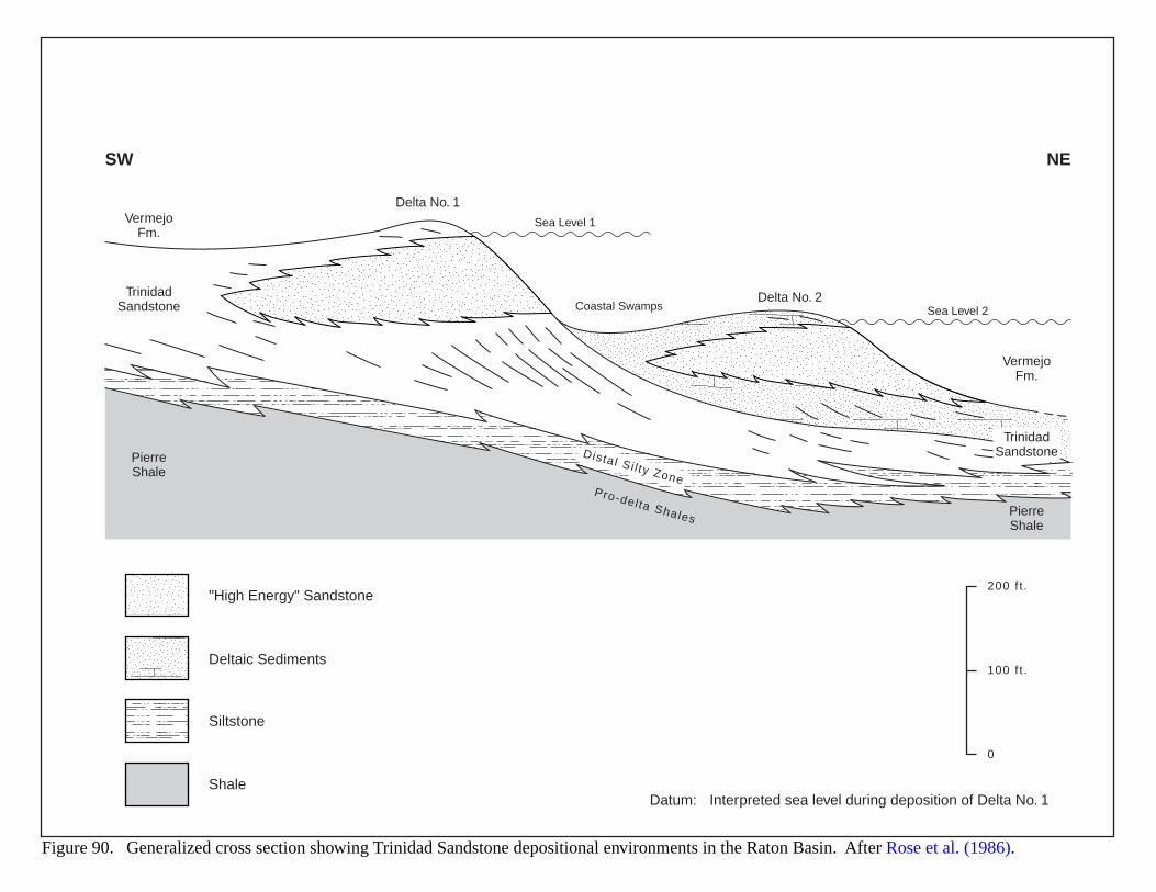
Figure 90. Generalized cross section showing Trinidad Sandstone depositional environments in the Raton Basin. After Rose et al. (1986).
SW NE
VermejoFm.
Delta No. 1
Delta No. 2
Sea Level 1
Coastal Swamps
Distal Si l ty ZonePro-del ta Shales
Sea Level 2
TrinidadSandstone
PierreShale
VermejoFm.
TrinidadSandstone
PierreShale
200 f t .
100 f t .
0
"High Energy" Sandstone
Siltstone
Deltaic Sediments
ShaleDatum: Interpreted sea level during deposition of Delta No. 1
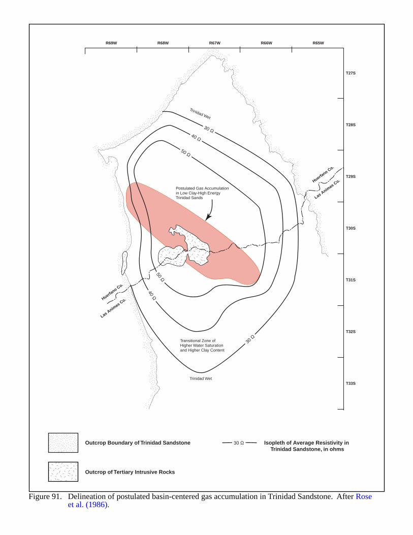
Transitional Zone ofHigher Water Saturationand Higher Clay Content
Postulated Gas Accumulationin Low Clay-High EnergyTrinidad Sands
Trinidad Wet
Trinidad Wet
30 Ω
30 Ω
40 Ω
40 Ω
50 Ω
50 Ω
Figure 91. Delineation of postulated basin-centered gas accumulation in Trinidad Sandstone. After Rose et al. (1986).
30 ΩOutcrop Boundary of Trinidad Sandstone Isopleth of Average Resistivity inTrinidad Sandstone, in ohms
Outcrop of Tertiary Intrusive Rocks
Las Animas Co.
Las Animas Co.Huerfa
no Co.
Huerfano Co.
R69W R68W R67W R66W R65W
T27S
T28S
T29S
T30S
T31S
T32S
T33S
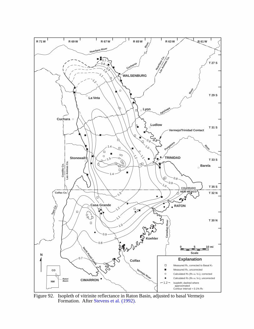
|
||
| |
||
|
1.0
0.9
0.8
0.8
0.8
0.9
1.0
0.7
0.7
1.1
1.1
1.2
1.2
1.3
1.4
1.4
1.5
1.2
1.1
1.0
1.0
0.9
0.9
0.8
R 71 W R 69 W R 67 W R 65 W R 63 W R 61 W
T 27 S
T 29 S
T 31 S
T 33 S
T 35 S
T 32 N
T 30 N
Calculated R0 (R0 vs. Vm), uncorrected
Calculated R0 (R0 vs. Vm), corrected
Measured R0, uncorrected
Measured R0, corrected to Basal Kv
Isopleth; dashed where approximatedContour interval = 0.1% R0
Figure 92. Isopleth of vitrinite reflectance in Raton Basin, adjusted to basal VermejoFormation. After Stevens et al. (1992).
Explanation
1.2
N
0 5
Scale
10 mi
CO
NMRatonBasin
Vermejo River
North Pontil Creek
Can
adia
n R
iver
Purgatoire River
Apishapa
Riv
er
Cucharas
Riv
er
Huerfano River
TRINIDAD
RATON
Koehler
Barela
Ludlow
Lyon
WALSENBURG
Cuchara
Stonewall
Casa Grande
Colfax
CIMARRON
La Veta
COLORADONEW MEXICO
Co
still
o C
o.
Las
An
imas
Co
.
Las
Ani
mas
Co.
Hue
rfan
o C
o.
Colfax Co.
Taos
Co.
Vermejo/Trinidad Contact
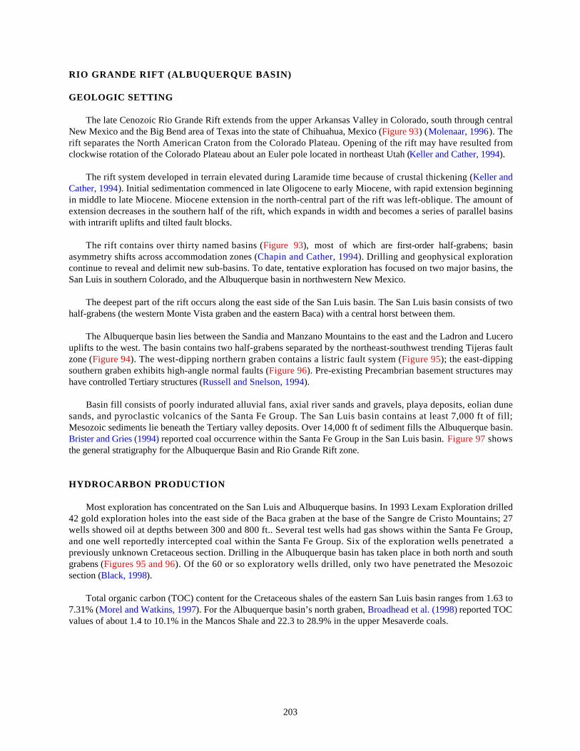
203
RIO GRANDE RIFT (ALBUQUERQUE BASIN)
GEOLOGIC SETTING
The late Cenozoic Rio Grande Rift extends from the upper Arkansas Valley in Colorado, south through centralNew Mexico and the Big Bend area of Texas into the state of Chihuahua, Mexico (Figure 93) (Molenaar, 1996). Therift separates the North American Craton from the Colorado Plateau. Opening of the rift may have resulted fromclockwise rotation of the Colorado Plateau about an Euler pole located in northeast Utah (Keller and Cather, 1994).
The rift system developed in terrain elevated during Laramide time because of crustal thickening (Keller andCather, 1994). Initial sedimentation commenced in late Oligocene to early Miocene, with rapid extension beginningin middle to late Miocene. Miocene extension in the north-central part of the rift was left-oblique. The amount ofextension decreases in the southern half of the rift, which expands in width and becomes a series of parallel basinswith intrarift uplifts and tilted fault blocks.
The rift contains over thirty named basins (Figure 93), most of which are first-order half-grabens; basinasymmetry shifts across accommodation zones (Chapin and Cather, 1994). Drilling and geophysical explorationcontinue to reveal and delimit new sub-basins. To date, tentative exploration has focused on two major basins, theSan Luis in southern Colorado, and the Albuquerque basin in northwestern New Mexico.
The deepest part of the rift occurs along the east side of the San Luis basin. The San Luis basin consists of twohalf-grabens (the western Monte Vista graben and the eastern Baca) with a central horst between them.
The Albuquerque basin lies between the Sandia and Manzano Mountains to the east and the Ladron and Lucerouplifts to the west. The basin contains two half-grabens separated by the northeast-southwest trending Tijeras faultzone (Figure 94). The west-dipping northern graben contains a listric fault system (Figure 95); the east-dippingsouthern graben exhibits high-angle normal faults (Figure 96). Pre-existing Precambrian basement structures mayhave controlled Tertiary structures (Russell and Snelson, 1994).
Basin fill consists of poorly indurated alluvial fans, axial river sands and gravels, playa deposits, eolian dunesands, and pyroclastic volcanics of the Santa Fe Group. The San Luis basin contains at least 7,000 ft of fill;Mesozoic sediments lie beneath the Tertiary valley deposits. Over 14,000 ft of sediment fills the Albuquerque basin.Brister and Gries (1994) reported coal occurrence within the Santa Fe Group in the San Luis basin. Figure 97 showsthe general stratigraphy for the Albuquerque Basin and Rio Grande Rift zone.
HYDROCARBON PRODUCTION
Most exploration has concentrated on the San Luis and Albuquerque basins. In 1993 Lexam Exploration drilled42 gold exploration holes into the east side of the Baca graben at the base of the Sangre de Cristo Mountains; 27wells showed oil at depths between 300 and 800 ft.. Several test wells had gas shows within the Santa Fe Group,and one well reportedly intercepted coal within the Santa Fe Group. Six of the exploration wells penetrated apreviously unknown Cretaceous section. Drilling in the Albuquerque basin has taken place in both north and southgrabens (Figures 95 and 96). Of the 60 or so exploratory wells drilled, only two have penetrated the Mesozoicsection (Black, 1998).
Total organic carbon (TOC) content for the Cretaceous shales of the eastern San Luis basin ranges from 1.63 to7.31% (Morel and Watkins, 1997). For the Albuquerque basin’s north graben, Broadhead et al. (1998) reported TOCvalues of about 1.4 to 10.1% in the Mancos Shale and 22.3 to 28.9% in the upper Mesaverde coals.

204
EVIDENCE FOR BASIN-CENTERED GAS
Possible basin-centered gas might occur within the Cretaceous section of the Baca Graben in the San Luis Basinand in the Cretaceous and Jurassic sections of the Albuquerque basin. The areal extent of any potential accumulationwithin the Mesozoic sediments remains unknown. Other basins within the Rockies with a similar Cretaceoussection such as the Piceance Basin do host basin-centered gas accumulations.
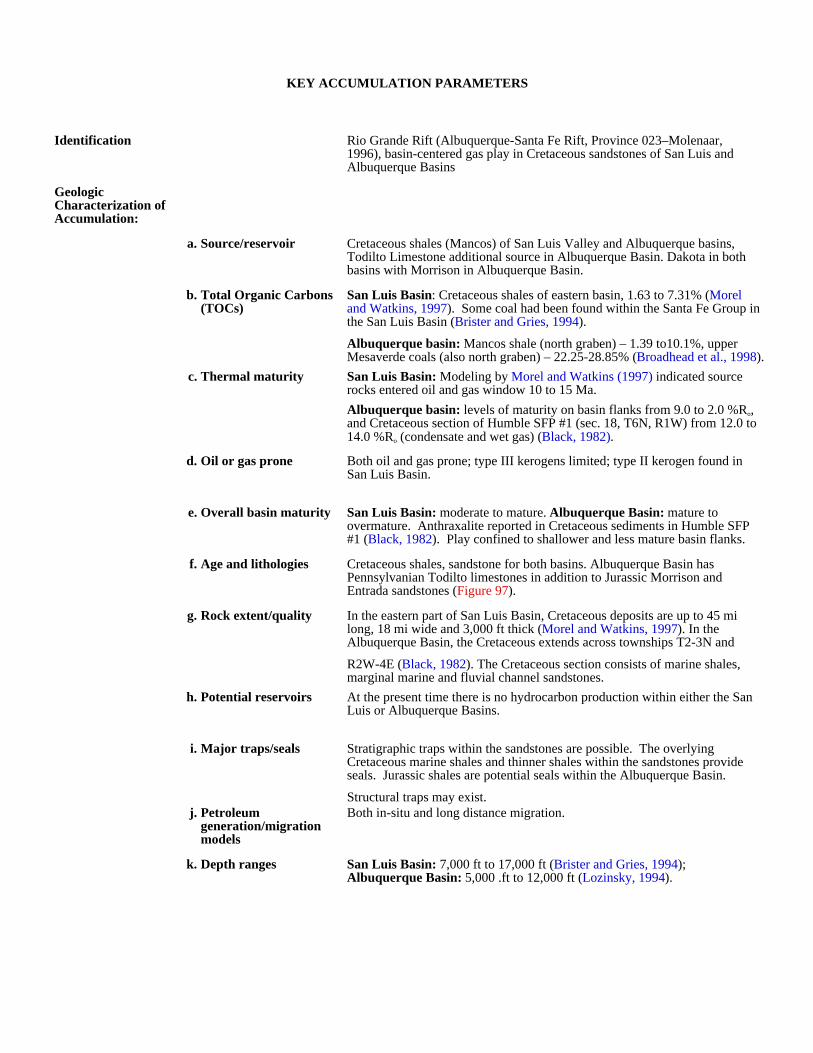
KEY ACCUMULATION PARAMETERS
Identification Rio Grande Rift (Albuquerque-Santa Fe Rift, Province 023–Molenaar, 1996), basin-centered gas play in Cretaceous sandstones of San Luis and Albuquerque Basins
Geologic Characterization of Accumulation:
a. Source/reservoir Cretaceous shales (Mancos) of San Luis Valley and Albuquerque basins, Todilto Limestone additional source in Albuquerque Basin. Dakota in both basins with Morrison in Albuquerque Basin.
b. Total Organic Carbons (TOCs)
San Luis Basin: Cretaceous shales of eastern basin, 1.63 to 7.31% (Morel and Watkins, 1997). Some coal had been found within the Santa Fe Group in the San Luis Basin (Brister and Gries, 1994).
Albuquerque basin: Mancos shale (north graben) – 1.39 to10.1%, upper Mesaverde coals (also north graben) – 22.25-28.85% (Broadhead et al., 1998).
c. Thermal maturity San Luis Basin: Modeling by Morel and Watkins (1997) indicated source rocks entered oil and gas window 10 to 15 Ma.
Albuquerque basin: levels of maturity on basin flanks from 9.0 to 2.0 %Ro, and Cretaceous section of Humble SFP #1 (sec. 18, T6N, R1W) from 12.0 to 14.0 %Ro (condensate and wet gas) (Black, 1982).
d. Oil or gas prone Both oil and gas prone; type III kerogens limited; type II kerogen found in San Luis Basin.
e. Overall basin maturity San Luis Basin: moderate to mature. Albuquerque Basin: mature to overmature. Anthraxalite reported in Cretaceous sediments in Humble SFP #1 (Black, 1982). Play confined to shallower and less mature basin flanks.
f. Age and lithologies Cretaceous shales, sandstone for both basins. Albuquerque Basin has Pennsylvanian Todilto limestones in addition to Jurassic Morrison and Entrada sandstones (Figure 97).
g. Rock extent/quality In the eastern part of San Luis Basin, Cretaceous deposits are up to 45 mi long, 18 mi wide and 3,000 ft thick (Morel and Watkins, 1997). In the Albuquerque Basin, the Cretaceous extends across townships T2-3N and
R2W-4E (Black, 1982). The Cretaceous section consists of marine shales, marginal marine and fluvial channel sandstones.
h. Potential reservoirs At the present time there is no hydrocarbon production within either the San Luis or Albuquerque Basins.
i. Major traps/seals Stratigraphic traps within the sandstones are possible. The overlying Cretaceous marine shales and thinner shales within the sandstones provide seals. Jurassic shales are potential seals within the Albuquerque Basin.
Structural traps may exist.j. Petroleum
generation/migration models
Both in-situ and long distance migration.
k. Depth ranges San Luis Basin: 7,000 ft to 17,000 ft (Brister and Gries, 1994); Albuquerque Basin: 5,000 .ft to 12,000 ft (Lozinsky, 1994).
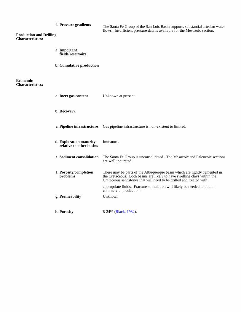
l. Pressure gradients The Santa Fe Group of the San Luis Basin supports substantial artesian water flows. Insufficient pressure data is available for the Mesozoic section.
Production and Drilling Characteristics:
a. Important fields/reservoirs
b. Cumulative production
Economic Characteristics:
a. Inert gas content Unknown at present.
b. Recovery
c. Pipeline infrastructure Gas pipeline infrastructure is non-existent to limited.
d. Exploration maturity relative to other basins
Immature.
e. Sediment consolidation The Santa Fe Group is unconsolidated. The Mesozoic and Paleozoic sections are well indurated.
f. Porosity/completion problems
There may be parts of the Albuquerque basin which are tightly cemented in the Cretaceous. Both basins are likely to have swelling clays within the Cretaceous sandstones that will need to be drilled and treated with
appropriate fluids. Fracture stimulation will likely be needed to obtain commercial production.
g. Permeability Unknown
h. Porosity 8-24% (Black, 1982).
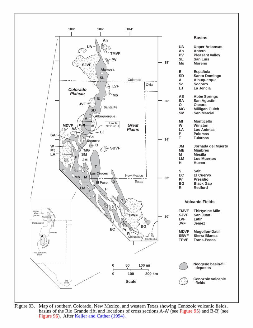
Figure 93. Map of southern Colorado, New Mexico, and western Texas showing Cenozoic volcanic fields, basins of the Rio Grande rift, and locations of cross sections A-A' (see Figure 95) and B-B' (seeFigure 96). After Keller and Cather (1994).
Neogene basin-fill deposits
Cenozoic volcanic fields
0 100 200 km
0 50 100 mi
Scale
UAAnPVSLMo
ESDAScLJ
ASSAOMGSM
MtWLAPT
JMMbMLMH
SECPrBGR
Upper ArkansasAnteroPleasant ValleySan LuisMoreno
EspañolaSanto DomingoAlbuquerqueSocorroLa Jencia
Abbe SpringsSan AgustinOscuraMilligan GulchSan Marcial
MonticelloWinstonLas AnimasPalomasTularosa
Jornada del MuertoMimbresMesillaLos MuertosHueco
SaltEl CuervoPresidioBlack GapRedford
TMVFSJVFLVFJVF
MDVFSBVFTPVF
Thirtynine MileSan JuanLatirJemez
Mogollon-DatilSierra BlancaTrans-Pecos
Basins
Volcanic FieldsSangre
deC
ristoM
tns
Manz
ano
-
Sandia
Mtn
s
BigBend
Baca graben
MonteVista
graben
AlbuquerqueBasin
Santa Fe
Alamosa
UA
An
TMVF
PV
LVF
Mo
SL
E
PLA
SALJ
MtW
T
O
S
H
ECBG
RPr
M
LM
Mb
SD
A
A
JVF
MDVFAS
Sc
SBVFMGSMJM
SJVF
TPVF
108°
38°
36°
34°
32°
30°
106° 104°
Colorado
ColoradoPlateau
GreatPlains
New Mexico
Alamosa
Santa Fe
Albuquerque
Socorro
Las Cruces
El Paso Texas
CoahuillaChihuahua
Okla
A
BA'B'
HumbleSTP No. 1
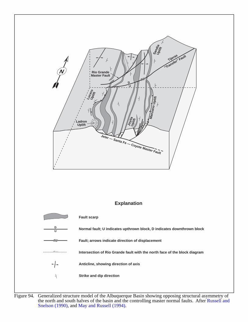
Figure 94. Generalized structure model of the Albuquerque Basin showing opposing structural asymmetry of the north and south halves of the basin and the controlling master normal faults. After Russell andSnelson (1990), and May and Russell (1994).
N
DU
Normal fault; U indicates upthrown block, D indicates downthrown block
Fault; arrows indicate direction of displacement
Intersection of Rio Grande fault with the north face of the block diagram
Anticline, showing direction of axis
Strike and dip direction
Fault scarp
Explanation
DU
LadronUplift
Rio GrandeMaster Fault
Jeter — Santa Fe — Coyote Master Fault
Tijeras
"Transfer" Fault
Luce
roU
plift
Joyi
taU
plift
Man
zan
o U
plif
tS
andi
aU
plift
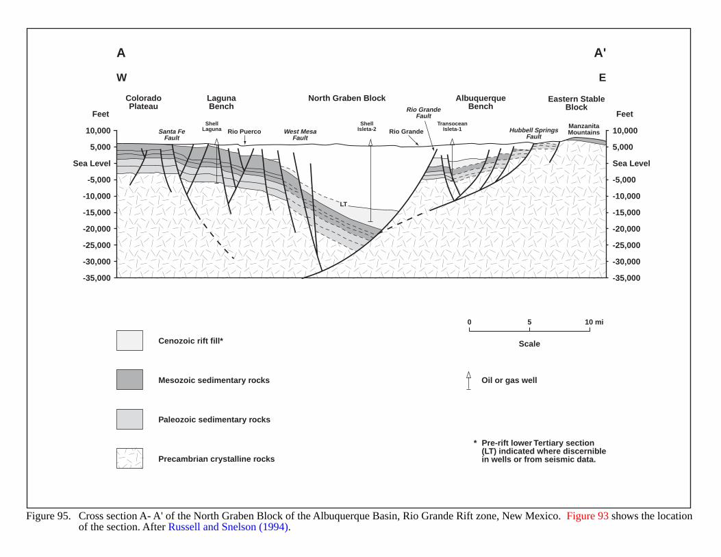
10,000
5,000
-5,000
-10,000
-15,000
-20,000
-25,000
-30,000
-35,000
Sea Level
10,000
5,000
-5,000
-10,000
-15,000
-20,000
-25,000
-30,000
-35,000
Sea Level
FeetFeet
Santa FeFault
West MesaFault
Rio GrandeFault
Hubbell SpringsFault
Rio Puerco Rio GrandeManzanitaMountains
ShellLaguna
ShellIsleta-2
TransoceanIsleta-1
ColoradoPlateau
LagunaBench
AlbuquerqueBench
North Graben Block Eastern StableBlock
W E
A A'
0 5 10 mi
ScaleCenozoic rift fill*
Mesozoic sedimentary rocks Oil or gas well
Paleozoic sedimentary rocks
Precambrian crystalline rocks
LT
* Pre-rift lower Tertiary section(LT) indicated where discerniblein wells or from seismic data.
Figure 95. Cross section A- A' of the North Graben Block of the Albuquerque Basin, Rio Grande Rift zone, New Mexico. Figure 93 shows the locationof the section. After Russell and Snelson (1994).
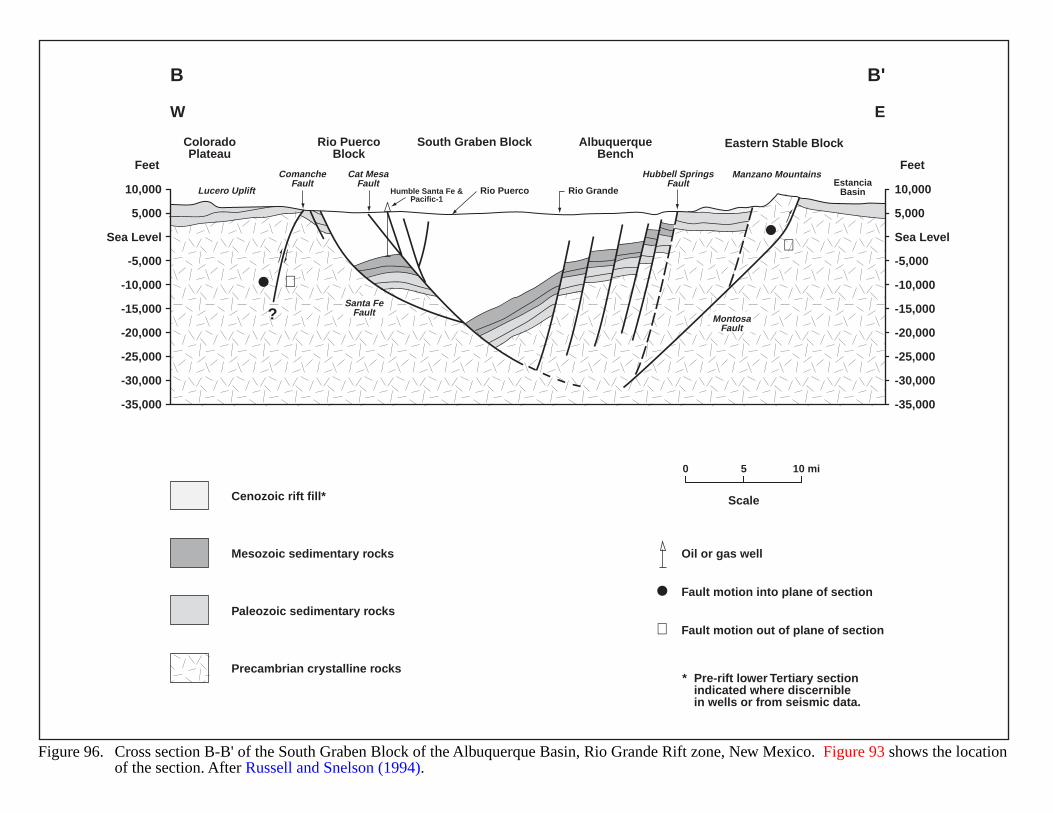
Figure 96. Cross section B-B' of the South Graben Block of the Albuquerque Basin, Rio Grande Rift zone, New Mexico. Figure 93 shows the locationof the section. After Russell and Snelson (1994).
0 5 10 mi
ScaleCenozoic rift fill*
Mesozoic sedimentary rocks
Paleozoic sedimentary rocks
Precambrian crystalline rocks* Pre-rift lower Tertiary section
indicated where discerniblein wells or from seismic data.
Lucero Uplift
Manzano MountainsCat MesaFault
ComancheFault
Santa FeFault
Hubbell SpringsFault
MontosaFault
Rio GrandeRio PuercoEstancia
BasinHumble Santa Fe &Pacific-1
ColoradoPlateau
Rio PuercoBlock
AlbuquerqueBench
South Graben Block Eastern Stable Block
W E
B B'
10,000
5,000
-5,000
-10,000
-15,000
-20,000
-25,000
-30,000
-35,000
Sea Level
10,000
5,000
-5,000
-10,000
-15,000
-20,000
-25,000
-30,000
-35,000
Sea Level
FeetFeet
Oil or gas well
Fault motion into plane of section
Fault motion out of plane of section⊕
⊕
?
⊕
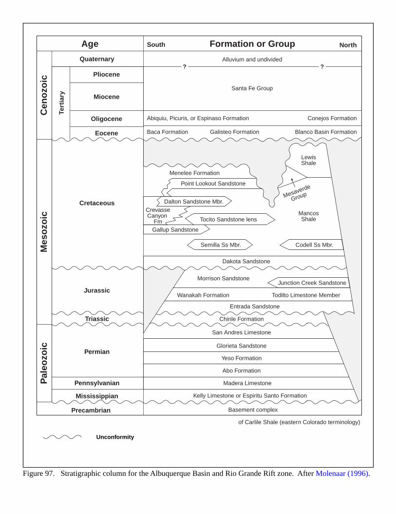
Figure 97. Stratigraphic column for the Albuquerque Basin and Rio Grande Rift zone. After Molenaar (1996).
Unconformity
AgeC
eno
zoic
Mes
ozo
icP
aleo
zoic
QuaternaryTe
rtia
ry
Cretaceous
Jurassic
Triassic
Permian
Pennsylvanian
Mississippian
Precambrian
Pliocene
South North
Miocene
Oligocene
Eocene
Formation or Group
Alluvium and undivided? ?
Santa Fe Group
Abiquiu, Picuris, or Espinaso Formation Conejos Formation
Baca Formation Galisteo Formation
Menelee Formation
CrevasseCanyon
Fm
Point Lookout Sandstone
Tocito Sandstone lens
Dalton Sandstone Mbr.
Semilla Ss Mbr. Codell Ss Mbr.
of Carlile Shale (eastern Colorado terminology)
Gallup Sandstone
Junction Creek Sandstone
Dakota Sandstone
Entrada Sandstone
Basement complex
Chinle Formation
San Andres Limestone
Glorieta Sandstone
Yeso Formation
Abo Formation
Madera Limestone
Kelly Limestone or Espiritu Santo Formation
Morrison Sandstone
Wanakah Formation Todilto Limestone Member
LewisShale
MancosShale
Mesaverde
Group
Blanco Basin Formation
212
SACRAMENTO BASIN
GEOLOGIC SETTING
The present day Sacramento Basin lies within California’s northwest-southeast trending Great Valley, betweenthe Sierra Nevada Range on the east, the Coast Ranges on the west, the Klamath Mountains to the north, and theStockton Arch on the south (Figure 98); the Stockton Arch separates the Sacramento from the adjoining San Joaquinbasin.
Structural development began in late Jurassic time as a forearc basin formed between the Sierra highlands on theeast and a wedge of Franciscan rock to the west. In early Cretaceous time, the basin began to fill with deep watersands and shales. By the late Cretaceous, delta-slope and turbidite fan systems dominated sedimentation, and the basindeveloped its characteristic asymmetry. The basin deep developed below the break in slope of the forearc’s shelf.
Structural styles differ across the basin. The eastern flank exhibits high angle normal faults typical ofextensional faulting of a stable shelf into an adjoining basin. Complex folding and faulting characterize thetectonically active western side. The Stockton Arch Fault developed at the close of the Cretaceous period and dividedthe forearc basin into the two present-day subbasins. Continued subsidence during the early Tertiary led to severalcycles of marine deposits overlain by non-marine sediments. Structural deformation continued throughout theTertiary, especially on the west sides of both basins (Callaway and Rennie, 1991; Montgomery, 1988c).
The Forbes Formation is a mud-rich turbidite fan system that prograded southward along the Sacramento Basinaxis (Imperato et al., 1990), and has historically had significant oil and gas development. This formationunconformably lies over the late Cretaceous Dobbins Shale, and in turn underlies the late Cretaceous Kione Deltaunits and Sacramento Shale (Figure 99).
HYDROCARBON PRODUCTION
Hydrocarbons in the Forbes usually occur in discreet, lenticular stratigraphic traps or in combination structural-stratigraphic traps, where structure has concentrated gas. Traps often involve multiple fault blocks with sealing faultsand can be quite complex. Productive sands have porosities of 30% and permeabilities of 100 md (millidarcies), andare usually 15 to 30 ft thick. Stacked sands often allow multiple completions in each well bore. In the northernSacramento Basin, the Forbes generally produces to a depth of 9,000 ft. Permeability decreases with depth, so fewwells have penetrated the Forbes in the deeper southern half of the basin. One now-abandoned well exceeded 11,000 ftdepth, but produced only a non-commercial 0.12 BCFG (Callaway and Rennie, 1991; Montgomery, 1988c;Weagant, 1972, 1986; and Zieglar and Spotts, 1978).
Overpressure often occurs in the Forbes Formation, and pressure gradients rise as high as 0.8 to 9 psi/ft below6,000 ft depth (Lico and Kharaka, 1983). In some cases, changes in pressure gradients may correlate withhydrodynamic gradients or the post-depositional emplacement of magmatic stocks. Overpressure along the westflank of the Sacramento and San Joaquin basins may have some relation to structural compression associated withMesozoic subduction and more recent plate movements (Montgomery, 1988c; and Weagant, 1972, 1986)
Shales of the Dobbins, the Sacramento and the Forbes formations are likely gas sources. Cretaceous shales ofthe Sacramento and northern San Joaquin basins generally contain less than 1.0% total organic content (TOC). Theorganic material is largely humic or non-sapropelic and therefore gas prone. Gas generation in Cretaceous rocksprobably began at burial depths of 13,000 to 15,000 ft (Figure 100). The “Delta depocenter” in the southernSacramento Basin was probably the major source for gas in this basin and for the gas fields in the northern SanJoaquin (Zieglar and Spotts, 1978; Callaway and Rennie, 1991).
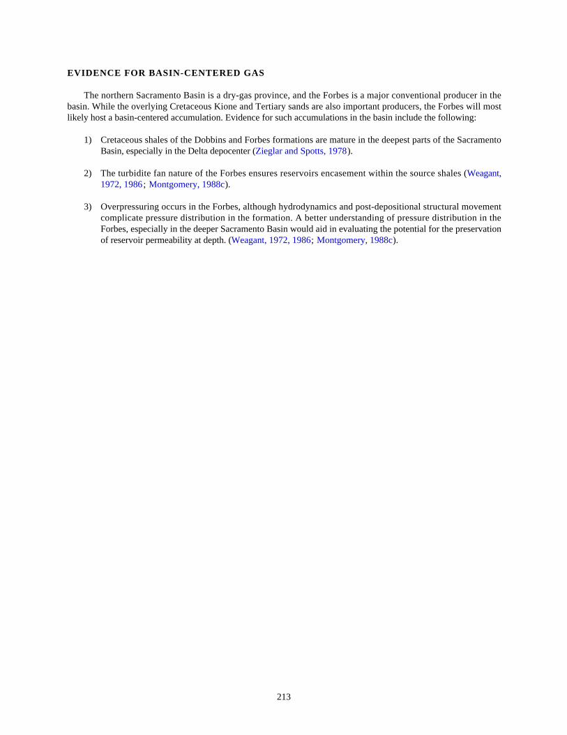
213
EVIDENCE FOR BASIN-CENTERED GAS
The northern Sacramento Basin is a dry-gas province, and the Forbes is a major conventional producer in thebasin. While the overlying Cretaceous Kione and Tertiary sands are also important producers, the Forbes will mostlikely host a basin-centered accumulation. Evidence for such accumulations in the basin include the following:
1) Cretaceous shales of the Dobbins and Forbes formations are mature in the deepest parts of the SacramentoBasin, especially in the Delta depocenter (Zieglar and Spotts, 1978).
2) The turbidite fan nature of the Forbes ensures reservoirs encasement within the source shales (Weagant,1972, 1986; Montgomery, 1988c).
3) Overpressuring occurs in the Forbes, although hydrodynamics and post-depositional structural movementcomplicate pressure distribution in the formation. A better understanding of pressure distribution in theForbes, especially in the deeper Sacramento Basin would aid in evaluating the potential for the preservationof reservoir permeability at depth. (Weagant, 1972, 1986; Montgomery, 1988c).
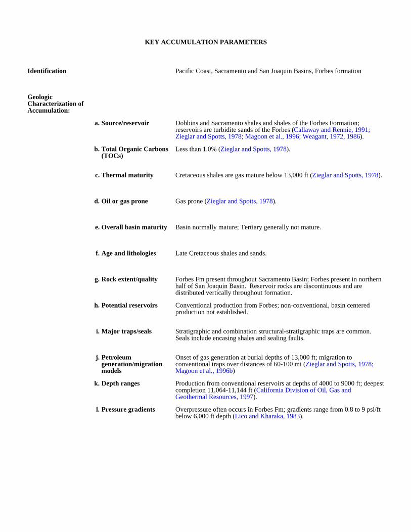
KEY ACCUMULATION PARAMETERS
Identification Pacific Coast, Sacramento and San Joaquin Basins, Forbes formation
Geologic Characterization of Accumulation:
a. Source/reservoir Dobbins and Sacramento shales and shales of the Forbes Formation; reservoirs are turbidite sands of the Forbes (Callaway and Rennie, 1991; Zieglar and Spotts, 1978; Magoon et al., 1996; Weagant, 1972, 1986).
b. Total Organic Carbons (TOCs)
Less than 1.0% (Zieglar and Spotts, 1978).
c. Thermal maturity Cretaceous shales are gas mature below 13,000 ft (Zieglar and Spotts, 1978).
d. Oil or gas prone Gas prone (Zieglar and Spotts, 1978).
e. Overall basin maturity Basin normally mature; Tertiary generally not mature.
f. Age and lithologies Late Cretaceous shales and sands.
g. Rock extent/quality Forbes Fm present throughout Sacramento Basin; Forbes present in northern half of San Joaquin Basin. Reservoir rocks are discontinuous and are distributed vertically throughout formation.
h. Potential reservoirs Conventional production from Forbes; non-conventional, basin centered production not established.
i. Major traps/seals Stratigraphic and combination structural-stratigraphic traps are common. Seals include encasing shales and sealing faults.
j. Petroleum generation/migration models
Onset of gas generation at burial depths of 13,000 ft; migration to conventional traps over distances of 60-100 mi (Zieglar and Spotts, 1978; Magoon et al., 1996b)
k. Depth ranges Production from conventional reservoirs at depths of 4000 to 9000 ft; deepest completion 11,064-11,144 ft (California Division of Oil, Gas and Geothermal Resources, 1997).
l. Pressure gradients Overpressure often occurs in Forbes Fm; gradients range from 0.8 to 9 psi/ft below 6,000 ft depth (Lico and Kharaka, 1983).
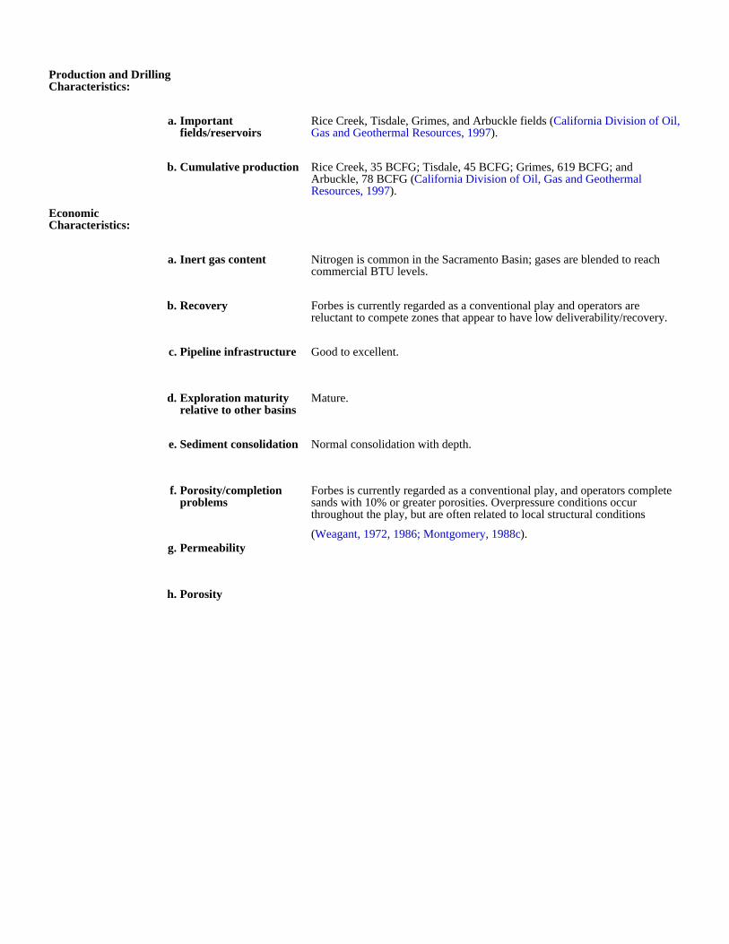
Production and Drilling Characteristics:
a. Important fields/reservoirs
Rice Creek, Tisdale, Grimes, and Arbuckle fields (California Division of Oil, Gas and Geothermal Resources, 1997).
b. Cumulative production Rice Creek, 35 BCFG; Tisdale, 45 BCFG; Grimes, 619 BCFG; and Arbuckle, 78 BCFG (California Division of Oil, Gas and Geothermal Resources, 1997).
Economic Characteristics:
a. Inert gas content Nitrogen is common in the Sacramento Basin; gases are blended to reach commercial BTU levels.
b. Recovery Forbes is currently regarded as a conventional play and operators are reluctant to compete zones that appear to have low deliverability/recovery.
c. Pipeline infrastructure Good to excellent.
d. Exploration maturity relative to other basins
Mature.
e. Sediment consolidation Normal consolidation with depth.
f. Porosity/completion problems
Forbes is currently regarded as a conventional play, and operators complete sands with 10% or greater porosities. Overpressure conditions occur throughout the play, but are often related to local structural conditions
(Weagant, 1972, 1986; Montgomery, 1988c).g. Permeability
h. Porosity
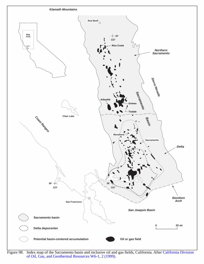
MapArea 40°
122°
38°
123°
38°
122°
San Francisco
Clear Lake
Red Bluff
Sacramento
Woodland
Sacram
ento Basin
Sierra N
evada
StocktonArch
San Joaquin Basin
Coast Ranges
Delta
NorthernSacramento
Rice Creek
Tisdale
Arbuckle
Grimes
Klamath Mountains
Figure 98. Index map of the Sacramento basin and inclusive oil and gas fields, California. After California Division of Oil, Gas, and Geothermal Resources W6-1, 2 (1999).
Sacramento basin
Delta depocenter
Potential basin-centered accumulation Oil or gas field
0 20 mi
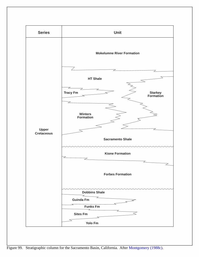
Series Unit
Mokelumne River Formation
UpperCretaceous
StarkeyFormation
WintersFormation
HT Shale
Sacramento Shale
Kione Formation
Forbes Formation
Tracy Fm
Dobbins Shale
Guinda Fm
Funks Fm
Sites Fm
Yolo Fm
Figure 99. Stratigraphic column for the Sacramento Basin, California. After Montgomery (1988c).
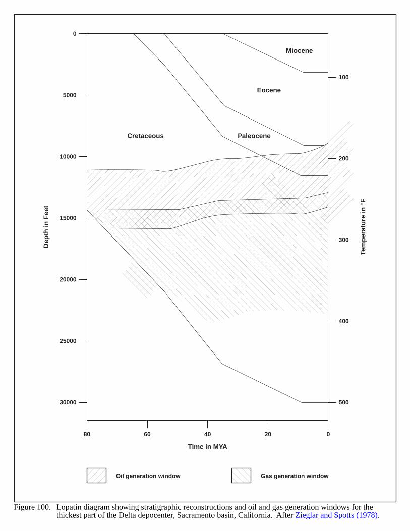
0
5000
10000
15000
20000
25000
30000
Dep
th in
Fee
t
Tem
per
atu
re in
°F
100
200
300
400
500
80 60 40 20 0
Time in MYA
Miocene
Eocene
PaleoceneCretaceous
Figure 100. Lopatin diagram showing stratigraphic reconstructions and oil and gas generation windows for thethickest part of the Delta depocenter, Sacramento basin, California. After Zieglar and Spotts (1978).
Oil generation window Gas generation window
219
SALTON TROUGH, CALIFORNIA
GEOLOGIC SETTING
The Salton Trough is an active rift basin lying within the Imperial Valley at the northern end of the Gulf ofCalifornia (Figure 101). The basin extends about 115 miles in length and 45 miles in width, and encompasses anarea of 4,500 square miles (Barker, 1996b). The rift apparently contains metamorphosed sediments, igneousintrusions and rising upper mantle material (Figure 102). The transfer zones between the major strike-slip faults mayhave active rhombic-shaped spreading centers, especially at the southern end of the Salton Sea and at Cerro Prieto(Figure 101) (Lonsdale, 1989; and Mueller and Rockwell, 1991).
Paleogeographic reconstructions show that the Gulf of California opened during middle Miocene time andreached its maximum northward extent in the early Pliocene (Smith, 1991). Deltaic and lacustrine sediments fromthe Colorado River filled the northern end of the Gulf of California beginning 5.5 Ma, eventually cutting it off fromthe marine seaway by 4 Ma (Schmidt, 1990). The basin now contains 16,000 to 20,000 ft of sediments andmetasediments, including Miocene to Pliocene-age evaporites, marine and continental deposits, and a thick section ofPleistocene to Recent deltaic and lacustrine sediments (Helgeson, 1968; Muffler and Doe, 1968). Figure 103 shows ageneral stratigraphic column for the Salton Trough (Muffler and Doe, 1968; Lucchitta, 1972). Dibblee (1984),Gibson et al. (1984), and Kerr and Kidwell (1991) have described the sedimentary formations exposed in outcropsalong the western and eastern flanks of the Salton Trough. Mesozoic igneous and metamorphic rocks form the baseof the exposed section. Above this crystalline basement are alluvial fans and breccias of the Miocene Anza and SplitMountain Formations. Interfingered with the Split Mountain is the Fish Creek Gypsum, a formation of gypsum andanhydrite that indicates rift basin development began in middle Miocene time. Breccias and marine turbidites overliethe evaporite beds and indicate rapid subsidence. The turbidites grade upward and laterally into shallow marineshoreline deposits of the Pliocene Imperial Formation. These are overlain by deltaic and lacustrine sedimentsdeposited by the Colorado River. This basin has continued to subside, and recent erosion has not removed anysediments.
Active strike-slip motion complicates the rift basin geology within the San Andreas, Imperial and Cerro Prietofault zones. Calculated slip rates for the various strike-slip faults in the Salton Trough range from 1.7 to 5.4 cm/year(Duffield, 1976; Suarez-Vidal et al., 1991). According to Elders (1979), the Salton Trough is one of the mostearthquake-prone areas in North America. The basin undergoes active deformation, as indicated by movementsobserved from tiltmeter and survey data. Lippmann and Manon (1987) described earthquake activity along theImperial and Cerro Prieto fault zones near Cerro Prieto geothermal field. Such seismic activity can potentiallydisrupt or breach hydrocarbon traps and pressure seals, preventing accumulation of hydrocarbons.
HYDROCARBON PRODUCTION
To date, the Salton Trough has no recorded hydrocarbon production.
220
EVIDENCE FOR BASIN-CENTERED GAS
According to gas sample data from geothermal wells and fumaroles, the main gas expelled in the basin is CO2.Most samples show 80 to 90 wt % CO2 and only 3 to 5 wt% of hydrocarbon gases (Nehring and D’Amore, 1981;1984). For many years a dry-ice factory produced CO2 from shallow wells near the Salton Sea.
Thermal gradients and maturity levels vary throughout the basin. In cooler areas, conditions may favorgeneration and expulsion of natural gas. However, Colorado River sediments apparently lack hydrocarbon sourcematerial. Analyses of deep-well cuttings show small amounts (< 0.5 wt%) of total organic carbon (TOC). The onlypotential source rocks noted in the geologic literature have been minute coal fragments: Nehring and D’Amore(1981, 1984) reported dispersed lignite particles in deltaic sediments from a deep well (Prian #1) near Cerro Pietro.This coaly material may possibly generate the small amounts of hydrocarbon gases found in Cerro Pietro geothermalwells. Published lithology logs and formation descriptions include no coal beds or swamp environments in thesedimentary section, so the origin, extent and depositional trend of the carbonaceous units remain unknown. Thelignite fragments in the Prian #1 well may represent allocthonous deposition of Cretaceous coal eroded from theColorado Plateau.
Vitrinite reflectance (Ro) measurements for several areas in the Salton Trough indicate high thermal maturation.Barker (1996b) reported an Ro of 3% at 13,400 ft in the Chevron Wilson #1 well (20-T14S-R15E). Drilled within arelatively cool part of the basin, this well had a temperature gradient of only 60 ° C/km.
Figure 104 shows a plot of vitrinite reflectance versus depth for several wells at the Cerro Prieto geothermalfield (Barker and Elders, 1981). The graph displays considerable variability in vitrinite gradients that probablydepends on proximity to a “hot spot.” Some wells show Ro ranges from 0.7 to 1.0% at depths as shallow as 800 to3,300 ft. In borehole M-84, vitrinite reflectance ranges from 0.12% at 790 ft to 4.1% at 5,580 ft (Barker and Elders,1981). These data indicate that thermal maturation levels have reached or exceeded the wet-gas floor and dry-gaspreservation limit (Dow, 1977) at very shallow depths in the hot spots.
Although under-explored parts of the basin may contain undiscovered coal seams or lacustrine shale beds withhigh organic content, the data apparently indicate “normal” pressures at depth throughout the section, andobservations lead to the conclusion that water has entirely saturated potential reservoir rocks. Thus, all the dataindicate the Salton Trough probably contains no basin-centered gas accumulation.
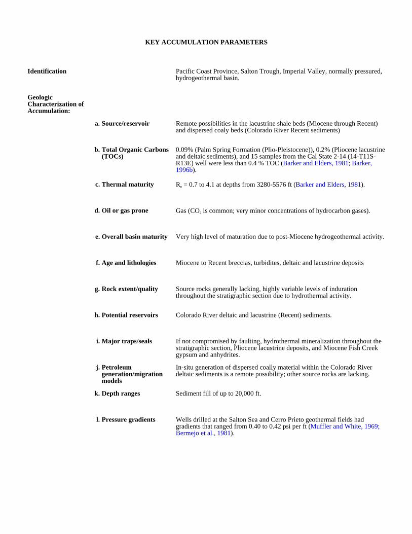
KEY ACCUMULATION PARAMETERS
Identification Pacific Coast Province, Salton Trough, Imperial Valley, normally pressured, hydrogeothermal basin.
Geologic Characterization of Accumulation:
a. Source/reservoir Remote possibilities in the lacustrine shale beds (Miocene through Recent) and dispersed coaly beds (Colorado River Recent sediments)
b. Total Organic Carbons (TOCs)
0.09% (Palm Spring Formation (Plio-Pleistocene)), 0.2% (Pliocene lacustrine and deltaic sediments), and 15 samples from the Cal State 2-14 (14-T11S-R13E) well were less than 0.4 % TOC (Barker and Elders, 1981; Barker, 1996b).
c. Thermal maturity Ro = 0.7 to 4.1 at depths from 3280-5576 ft (Barker and Elders, 1981).
d. Oil or gas prone Gas (CO2 is common; very minor concentrations of hydrocarbon gases).
e. Overall basin maturity Very high level of maturation due to post-Miocene hydrogeothermal activity.
f. Age and lithologies Miocene to Recent breccias, turbidites, deltaic and lacustrine deposits
g. Rock extent/quality Source rocks generally lacking, highly variable levels of induration throughout the stratigraphic section due to hydrothermal activity.
h. Potential reservoirs Colorado River deltaic and lacustrine (Recent) sediments.
i. Major traps/seals If not compromised by faulting, hydrothermal mineralization throughout the stratigraphic section, Pliocene lacustrine deposits, and Miocene Fish Creek gypsum and anhydrites.
j. Petroleum generation/migration models
In-situ generation of dispersed coally material within the Colorado River deltaic sediments is a remote possibility; other source rocks are lacking.
k. Depth ranges Sediment fill of up to 20,000 ft.
l. Pressure gradients Wells drilled at the Salton Sea and Cerro Prieto geothermal fields had gradients that ranged from 0.40 to 0.42 psi per ft (Muffler and White, 1969; Bermejo et al., 1981).

Production and Drilling Characteristics:
a. Important fields/reservoirs
none
b. Cumulative production none
Economic Characteristics:
a. Inert gas content High CO2 (80 to 90 wt%).
b. Recovery
c. Pipeline infrastructure poor
d. Exploration maturity relative to other basins
e. Sediment consolidation Poorly consolidated sediments, except in the vicinity of geothermal anomalies where hydrothermal fluids have effectively cemented thousands of feet of section.
f. Porosity/completion problems
Sediments deposited are mineralogically complex with a variety of clays; also problematic are well indurated rocks in geothermal areas.
g. Permeability
h. Porosity
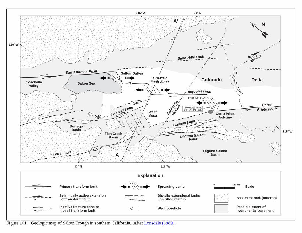
A
A'
?Brawley
Fault Zone
WestMesa
Sand Hills Fault
San Andreas Fault
Imperial Fault
Cucapa Fault
Elsinore Fault
CerroPrieto Fault
Laguna SaladaFault
San Jacinto Fault Zone
Colo
radoR
iverArizona
Mexico
Cal
iforn
iaM
exic
o
Cerro PrietoVolcano
Laguna SaladaBasin
Colorado Delta
Fish CreekBasin
BorregoBasin
CoachellaValley
Salton Sea
Salton Buttes
116° W
115° W
115° W
33° N
33° N 116° W
Prian No. 1
Boreholes M-84,-93, -94, and -105
Figure 101. Geologic map of Salton Trough in southern California. After Lonsdale (1989).
Spreading center
Well; borehole
Dip-slip extensional faults on rifted margin
Primary transform fault
Seismically active extension of transform fault
Inactive fracture zone or fossil transform fault
Basement rock (outcrop)
Scale
Possible extent of continental basement
Explanation
N
0 20 km
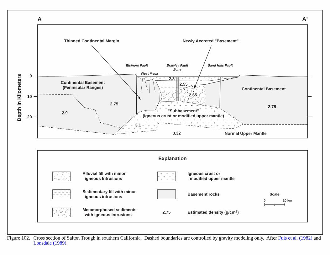
2.752.75
3.32
2.65
2.55
2.9
3.1
2.3Continental Basement(Peninsular Ranges)
Thinned Continental Margin Newly Accreted "Basement"
Continental Basement
Normal Upper Mantle
"Subbasement"(igneous crust or modified upper mantle)
Elsinore Fault
West Mesa
Sand Hills FaultBrawley FaultZone
0
10
20Dep
th in
Kilo
met
ers
A A'
Figure 102. Cross section of Salton Trough in southern California. Dashed boundaries are controlled by gravity modeling only. After Fuis et al. (1982) andLonsdale (1989).
Alluvial fill with minor igneous Intrusions
Sedimentary fill with minor igneous intrusions
Metamorphosed sediments with igneous intrusions
Scale
0 20 km
Explanation
Igneous crust or modified upper mantle
Basement rocks
Estimated density (g/cm3)2.75
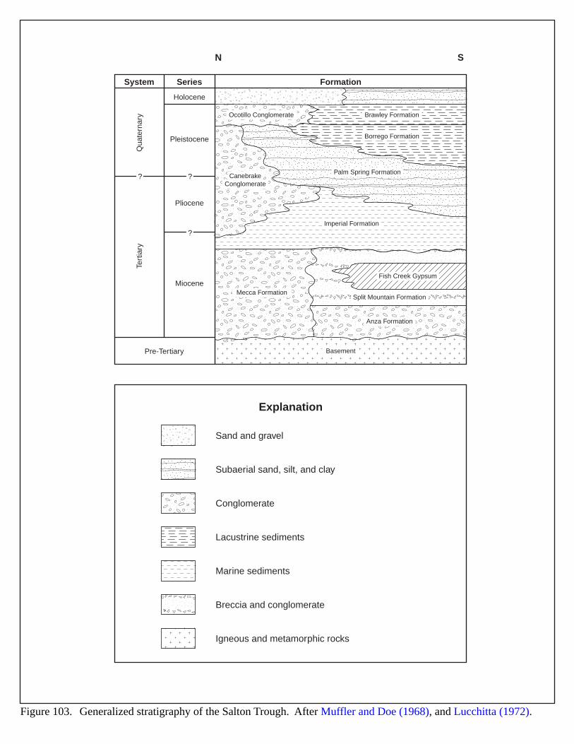
N S
Ocotillo Conglomerate
CanebrakeConglomerate
Brawley Formation
Borrego Formation
Palm Spring Formation
Imperial Formation
Mecca Formation
Fish Creek Gypsum
Split Mountain Formation
Anza Formation
Basement
System
Qua
tern
ary
Tert
iary
Series
Holocene
Pleistocene
Pliocene
Miocene
Pre-Tertiary
Formation
?
?
?
Sand and gravel
Subaerial sand, silt, and clay
Conglomerate
Lacustrine sediments
Marine sediments
Breccia and conglomerate
Igneous and metamorphic rocks
Explanation
Figure 103. Generalized stratigraphy of the Salton Trough. After Muffler and Doe (1968), and Lucchitta (1972).
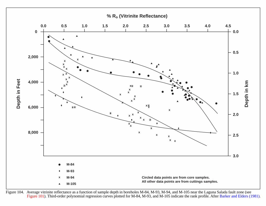
0.00.0
0.5
1.0
1.5
2.0
2.5
3.0
0
2,000
4,000
6,000
8,000
4.54.03.53.02.52.01.51.00.5
Figure 104. Average vitrinite reflectance as a function of sample depth in boreholes M-84, M-93, M-94, and M-105 near the Laguna Salada fault zone (seeFigure 101). Third-order polynomial regression curves plotted for M-84, M-93, and M-105 indicate the rank profile. After Barker and Elders (1981).
M-84
M-105
M-93
M-94x Circled data points are from core samples.All other data points are from cuttings samples.
Dep
th in
km
Dep
th in
Fee
t% Ro (Vitrinite Reflectance)
x xx
x xxx
x
x
xx
xx
xx
xx x
x xx
xxxx
x xx
xxx
x
xxxx x
x
x
x x
227
SAN RAFAEL SWELL (DAKOTA FORMATION)
GEOLOGIC SETTING
The San Rafael Swell is an uplift located on the northwest side of the Paradox Basin in north-central Utah(Figure 105). Two sub-parallel rows of southward-facing cliffs, the Book Cliffs and the Roan Cliffs, rim the Swellon the northeast, and the high-plateau volcanic area near Richfield forms the southwest border. Rocks in the SanRafael Swell range in age from Permian through Cretaceous, with Eocene strata exposed to the north as the Swellmerges with the south limb of the Uinta Basin (Figure 106). Maximum thickness of Phanerozoic sediments on theSwell ranges from 5,000 to 8,000 feet.
The Lower Cretaceous in this area includes the Cedar Mountain Formation (Albian), unconformably overlain bythe Dakota Sandstone (Cenomanian), which is in turn unconformably overlain by the Tununk Member of theMancos Shale (Turonian) (Young, 1960). The Dakota Sandstone and Cedar Mountain Formation comprise theDakota Group. Spieker (1946) designated the entire Cretaceous interval as the Indianola Group (Figure 107).
The Dakota Group rocks derive from formations uplifted and thrusted eastward during the Sevier orogeny(Lawton, 1983, 1985; Peterson, 1994a). Deposition occurred along the western shore of a Cretaceous seaway thattraversed the continent from Mexico to the Arctic. Dakota sediments uncomformably onlap the Morrison Formationon the west and grade eastward into a marine shale (Figure 107) (McGookey et al., 1972). The Dakota Grouprepresents four major stratigraphic sequences which reflect regional base-level fluctuations caused by both tectonicsand eustatic sea level changes. Multiple unconformities and smaller-scale sequences occur within each megasequence,in response to variations in sediment supply, climatic fluctuations and local structural developments (Dolson andMuller, 1994). Elder and Kirkland (1964) present a relative sea-level curve and ammonite zonation for theCenomanian of central Utah.
Peterson (1969) subdivided the Dakota Formation into three lithic units: a lower conglomeratic sandstone andshale unit from 0 to 65 ft thick; a middle carbonaceous shale, coal and sandstone unit from 0 to 80 ft thick; and anupper marine sandstone unit from 0 to 85 ft thick. The upper unit contains a large and diverse marine molluscanfaunal assemblage, consisting mostly of bivalves and ammonites (Eaton et al., 1990). Sandstones in the Dakotagenerally thicken and coarsen westward.
The San Rafael Swell resulted from basement uplift and thin-skinned deformation, where the eastward-vergingSevier orogenic belt impinged on the nearly horizontal strata of the Colorado Plateau. Exposures on the west flankof the Swell show detachment folds occur above a décollement in the Jurassic Carmel Formation, where a fold trainlies above a thin gypsum layer. These folds developed in response to regional horizontal compression on the westlimb of the Swell during Paleocene time (Royse, 1996). This décollement represents part of a stratigraphically-controlled regional detachment that occupies the east flank of the Jurassic evaporite basin.
The Swell first became active as a region of reduced subsidence before it developed topographic relief. It began togrow in mid-Cretaceous time (about 90 Ma) as a low-relief structural welt in the Rocky Mountain foreland (Perryand Flores, 1997). Giuseppe and Heller (1996) compared sections of the Price River Formation (Campanian) to thelaterally equivalent Farrer Formation and found variations across the swell crest, demonstrating tectonic uplift in LateCretaceous time.
228
HYDROCARBON POTENTIAL
In central Utah very little exploration has occurred for Permian, Triassic and Cretaceous reservoirs. The flanksof the north end of the San Rafael Swell and the Circle Cliffs uplift represent prospective areas for both structuraland stratigraphic traps (Sprinkel et al., 1997). Known petroleum resources of the area include gas in the TriassicMoenkopi Formation, the Cretaceous Ferron and Dakota Sandstones, and the Eocene Wasatch and Green RiverFormations (Figure 106). The Dakota Sandstone and Moenkopi Formation also contain small quantities of oil. Tarsands are common in the Moenkopi, and oil shale occurs in the Green River Formation. Weiss et al. (1990), andBishop and Tripp (1993) reported extraction of some tar sands for local use, but the oil shale remains unexploited.
Dakota Group rocks have yielded more than 2.0 BBOE of hydrocarbons, mostly from stratigraphic trapscontrolled by paleotopography (Dolson and Muller, 1994). The Moenkopi has produced significant quantities of oilfrom the Grassy Trail Creek field in the Swell.
Nine gas fields exist in the area, in addition to Farnham Dome (carbon dioxide production) and Woodside Dome(helium reserves) (Production table, Key Accumulation Parameters). Two fields, the Flat Canyon and Joe’s Valley,have produced natural gas from Dakota Formation reservoirs in the Wasatch Plateau adjacent to the San RafaelSwell. Dakota production may also have occurred from the abandoned Miller Creek field near Price, Utah; this fieldis located on the northwest plunge of the Swell.
EVIDENCE FOR BASIN-CENTERED GAS
The Dakota Sandstone in the area north of the San Rafael swell exhibits some characteristics indicative of abasin centered gas accumulation; however, overall evidence suggests that it probably is not. The Dakota containscoal and carbonaceous shale, which are good source rocks for gas. Additionally, the thermal maturity of these sourcerocks is adequate for thermogenic gas generation, especially where the Dakota becomes more deeply buried in theUinta-Piceance basin. Factors that do not favor the presence of a basin-centered accumulation include the following:
1) most fields are associated with structures, and
2) the limited production in the area looks to be conventional (i.e. reservoirs contain gas-water contacts).
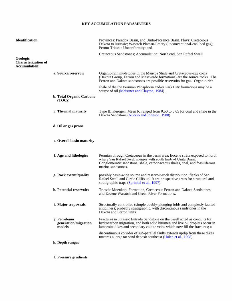
KEY ACCUMULATION PARAMETERS
Identification Provinces: Paradox Basin, and Uinta-Piceance Basin. Plays: Cretaceous Dakota to Jurassic; Wasatch Plateau-Emery (unconventional-coal bed gas); Permo-Triassic Unconformity; and
Cretaceous Sandstones; Accumulation: North end, San Rafael SwellGeologic Characterization of Accumulation:
a. Source/reservoir Organic-rich mudstones in the Mancos Shale and Cretaceous-age coals (Dakota Group, Ferron and Mesaverde formations) are the source rocks. The Ferron and Dakota sandstones are possible reservoirs for gas. Organic-rich
shale of the the Permian Phosphoria and/or Park City formations may be a source of oil (Meissner and Clayton, 1984).
b. Total Organic Carbons (TOCs)
c. Thermal maturity Type III Kerogen. Mean Ro ranged from 0.50 to 0.65 for coal and shale in the Dakota Sandstone (Nuccio and Johnson, 1988).
d. Oil or gas prone
e. Overall basin maturity
f. Age and lithologies Permian through Cretaceous in the basin area; Eocene strata exposed to north where San Rafael Swell merges with south limb of Uinta Basin. Conglomeratic sandstone, shale, carbonaceous shales, coal, and fossiliferous marine sandstones.
g. Rock extent/quality possibly basin-wide source and reservoir-rock distribution; flanks of San Rafael Swell and Circle Cliffs uplift are prospective areas for structural and stratigraphic traps (Sprinkel et al., 1997).
h. Potential reservoirs Triassic Moenkopi Formation, Cretaceous Ferron and Dakota Sandstones, and Eocene Wasatch and Green River Formations.
i. Major traps/seals Structurally controlled (simple doubly-plunging folds and complexly faulted anticlines); probably stratigraphic, with discontinous sandstones in the Dakota and Ferron units.
j. Petroleum generation/migration models
Fractures in Jurassic Entrada Sandstone on the Swell acted as conduits for hydrocarbon migration, and both solid bitumen and live oil droplets occur in lamproite dikes and secondary calcite veins which now fill the fractures; a
discontinuous corridor of sub-parallel faults extends updip from these dikes towards a large tar sand deposit southeast (Hulen et al., 1998).
k. Depth ranges
l. Pressure gradients
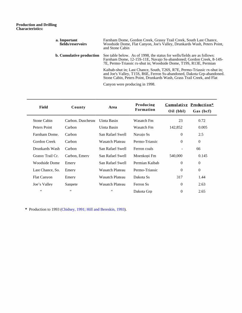
Production and Drilling Characteristics:
a. Important fields/reservoirs
Farnham Dome, Gordon Creek, Grassy Trail Creek, South Last Chance, Woodside Dome, Flat Canyon, Joe's Valley, Drunkards Wash, Peters Point, and Stone Cabin
b. Cumulative production See table below. As of 1998, the status for wells/fields are as follows: Farnham Dome, 12-15S-11E, Navajo Ss-abandoned; Gordon Creek, 8-14S-7E, Permo-Triassic rx-shut in; Woodside Dome, T19S, R13E, Permian
Kaibab-shut in; Last Chance, South, T26S, R7E, Permo-Triassic rx-shut in; and Joe's Valley, T15S, R6E, Ferron Ss-abandoned, Dakota Grp-abandoned. Stone Cabin, Peters Point, Drunkards Wash, Grass Trail Creek, and Flat
Canyon were producing in 1998.
* Production to 1993 (Chidsey, 1991; Hill and Bereskin, 1993).
Field County AreaProducingFormation
Cumulative
Oil (bbl)
Production*
Gas (bcf)
Stone Cabin Carbon, Duschesne Uinta Basin Wasatch Fm 23 0.72
Peters Point Carbon Uinta Basin Wasatch Fm 142,852 0.005
Farnham Dome. Carbon San Rafael Swell Navajo Ss 0 2.5
Gordon Creek Carbon Wasatch Plateau Permo-Triassic 0 0
Drunkards Wash Carbon San Rafael Swell Ferron coals - 66
Grassy Trail Cr. Carbon, Emery San Rafael Swell Moenkopi Fm 540,000 0.145
Woodside Dome Emery San Rafael Swell Permian Kaibab 0 0
Last Chance, So. Emery Wasatch Plateau Permo-Triassic 0 0
Flat Canyon Emery Wasatch Plateau Dakota Ss 317 1.44
Joe’s Valley Sanpete Wasatch Plateau Ferron Ss 0 2.63
“ “ “ Dakota Grp 0 2.65

Economic Characteristics:
a. Inert gas content
b. Recovery
c. Pipeline infrastructure
d. Exploration maturity relative to other basins
e. Sediment consolidation
f. Porosity/completion problems
g. Permeability
h. Porosity
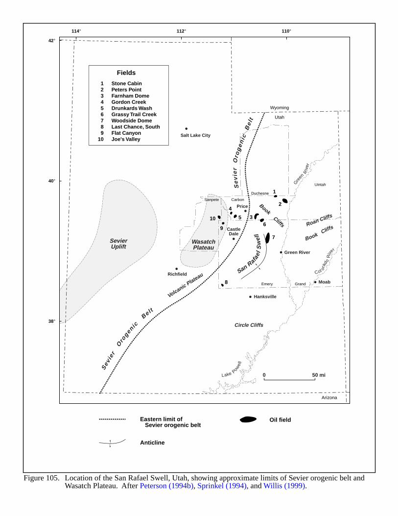
0 50 mi
Eastern limit of Sevier orogenic belt
Anticline
Oil field
Figure 105. Location of the San Rafael Swell, Utah, showing approximate limits of Sevier orogenic belt andWasatch Plateau. After Peterson (1994b), Sprinkel (1994), and Willis (1999).
Sev
ie
rOro
genicBelt
Se
vie
rO
rog
en
icB
elt
San Rafael
Sw
ell
SevierUplift
WasatchPlateau
Circle Cliffs
Volcanic Plateau
BookCliffs
Book CliffsRoan Cliffs
Salt Lake City
Green River
Moab
Price
Hanksville
Richfield
CastleDale
114°
42°
40°
38°
112° 110°
Gre
enR
iver
Col ora
doR
ive
r
Lake Powel
l
Wyoming
Utah
Arizona
Emery
Carbon
Duchesne
Sanpete
Uintah
Grand
10
9
4
5
1
2
36
7
8
123456789
10
Stone CabinPeters PointFarnham DomeGordon CreekDrunkards WashGrassy Trail CreekWoodside DomeLast Chance, SouthFlat CanyonJoe's Valley
Fields
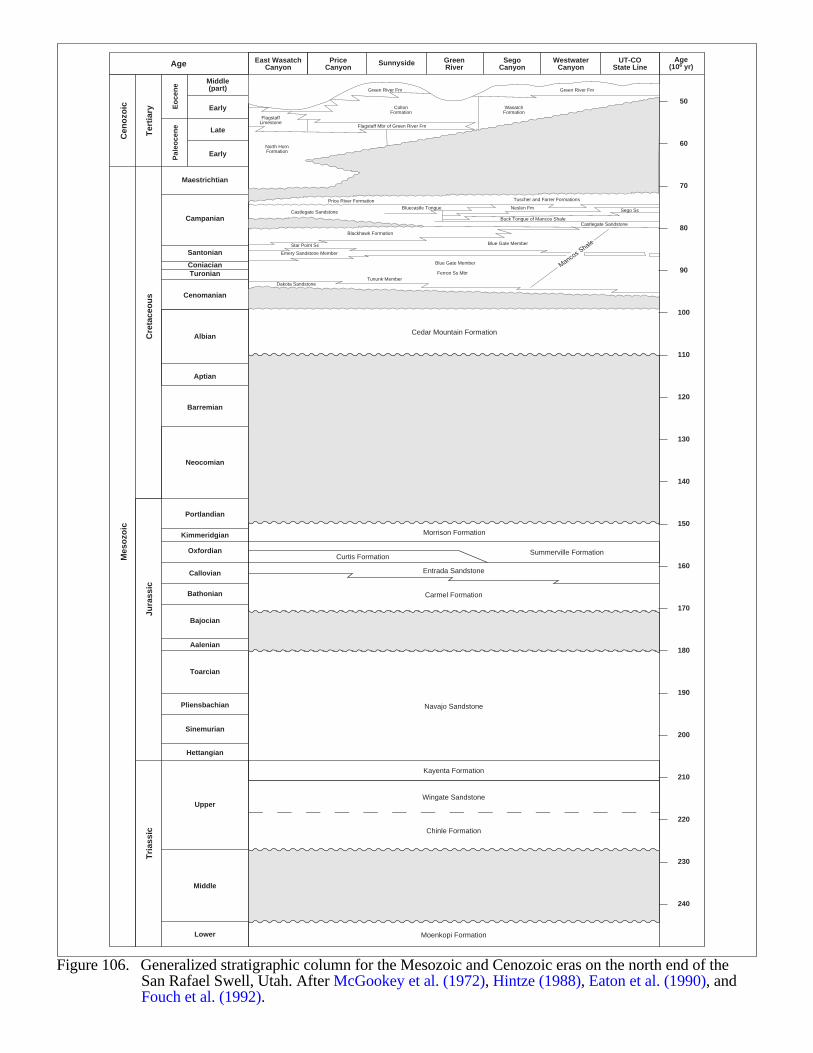
ColtonFormation
Dark Canyonsequence of Wasatch Fm
Cedar Mountain Formation
Morrison Formation
Summerville FormationCurtis Formation
Entrada Sandstone
Carmel Formation
Kayenta Formation
Navajo Sandstone
Wingate Sandstone
Chinle Formation
Moenkopi Formation
Star Point Ss
Middle(part)
Early
PriceCanyon
SunnysideAge GreenRiver
SegoCanyon
WestwaterCanyon
UT-COState Line
Age(106 yr)
East WasatchCanyon
Cen
ozo
ic
Ter
tiar
y Eo
cen
eP
aleo
cen
e
Cre
tace
ou
sJu
rass
icT
rias
sic
Mes
ozo
icLate
Early
Maestrichtian
Campanian
Santonian
ConiacianTuronian
Cenomanian
Albian
Aptian
Barremian
North HornFormation
WasatchFormation
FlagstaffLimestone
Green River Fm
Flagstaff Mbr of Green River Fm
Castlegate SandstoneBluecastle Tongue
Castlegate SandstoneBuck Tongue of Mancos Shale
Neslen Fm Sego Ss
Price River Formation
Blackhawk Formation
Blue Gate Member
Blue Gate Member
Emery Sandstone Member
Dakota Sandstone
Ferron Ss MbrTununk Member
Tuscher and Farrer Formations
Green River Fm
Mancos S
hale
Neocomian
Portlandian
Kimmeridgian
Oxfordian
Callovian
Bathonian
Bajocian
Aalenian
Toarcian
Pliensbachian
Sinemurian
Hettangian
Upper
Middle
Lower
50
60
70
80
90
100
110
120
130
140
150
160
170
180
190
200
210
220
230
240
Figure 106. Generalized stratigraphic column for the Mesozoic and Cenozoic eras on the north end of theSan Rafael Swell, Utah. After McGookey et al. (1972), Hintze (1988), Eaton et al. (1990), andFouch et al. (1992).
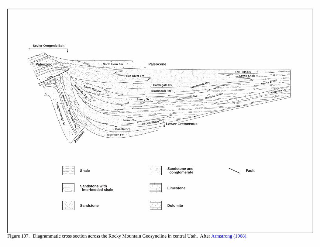
North Horn Fm
Morrison Fm
South Flat Fm
Price River Fm
Indianola Grp
Mesaverde Grp
Fox Hills Ss
Niobrara Ls
Lewis Shale
Pierre Shale
Mancos Shale
Aspen Shale
Dakota Grp
Castlegate Ss
Blackhawk Fm
Sevier Orogenic Belt
Emery Ss
Ferron Ss
Nugget-N
avajo Ss
Arapien Fm
- Twist G
ulch Fm
Jura
ssic
Paleozoic Paleocene
Lower Cretaceous
Figure 107. Diagrammatic cross section across the Rocky Mountain Geosyncline in central Utah. After Armstrong (1968).
Shale
Sandstone with interbedded shale
Sandstone
Sandstone and conglomerate Fault
Limestone
Dolomite
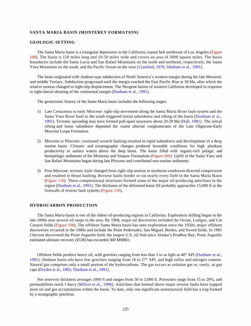
235
SANTA MARIA BASIN (MONTEREY FORMATION)
GEOLOGIC SETTING
The Santa Maria basin is a triangular depression in the California coastal belt northwest of Los Angeles (Figure108). The basin is 150 miles long and 10-50 miles wide and covers an area of 3000 square miles. The basinboundaries include the Santa Lucia and San Rafael Mountains on the north and northeast, respectively, the SantaYnez Mountains on the south, and the Pacific Ocean on the west (Crawford, 1970; Dunham et al., 1991).
The basin originated with Andean-type subduction of North America’s western margin during the late Mesozoicand middle Tertiary. Subduction progressed until the margin reached the East Pacific Rise at 30 Ma, after which therelative motion changed to right-slip displacement. The Neogene basins of western California developed in responseto right-lateral shearing of the continental margin (Dunham et al., 1991).
The geotectonic history of the Santa Maria basin includes the following stages:
1) Late Cretaceous to early Miocene: right-slip movement along the Santa Maria River fault system and theSanta Ynez River fault to the south triggered initial subsidence and rifting of the basin (Dunham et al.,1991). Tectonic spreading may have formed pull-apart structures about 20-28 Ma (Hall, 1981). The initialrifting and basin subsidence deposited the coarse alluvial conglomerates of the Late Oligocene-EarlyMiocene Lospe Formation.
2) Miocene to Pliocene: continued wrench faulting resulted in rapid subsidence and development of a deepmarine basin. Climatic and oceanographic changes produced favorable conditions for high planktonproductivity in surface waters above the deep basin. The basin filled with organic-rich pelagic andhemipelagic sediments of the Monterey and Sisquoc Formations (Figure 109). Uplift of the Santa Ynez andSan Rafael Mountains began during late Pliocene and contributed non-marine sediments.
3) Post-Miocene: tectonic style changed from right-slip motion to northeast-southwest-directed compressionand resulted in thrust faulting. Reverse faults border or cut nearly every field in the Santa Maria Basin(Figure 110). These compressional structures formed some of the major oil-producing anticlines in theregion (Dunham et al., 1991). The thickness of the deformed basin fill probably approaches 15,000 ft in thefootwalls of reverse fault systems (Figure 110).
HYDROCARBON PRODUCTION
The Santa Maria basin is one of the oldest oil-producing regions in California. Exploratory drilling began in thelate 1890s near several oil seeps in the area. By 1908, major oil discoveries included the Orcutt, Lompoc, and CatCanyon fields (Figure 108). The offshore Santa Maria basin has seen exploration since the 1950s; major offshorediscoveries occurred in the 1980s and include the Point Pedernales, San Miguel, Bonito, and Sword fields. In 1981Chevron discovered the Point Arguello field, the largest U.S. oil find since Alaska’s Prudhoe Bay; Point Arguelloestimated ultimate recovery (EUR) has exceeded 300 MMBO.
Offshore fields produce heavy oil, with gravities ranging from less than 5 to as light as 40° API (Dunham et al.,1991). Onshore basin oils have low gravities ranging from 16 to 27° API, and high sulfur and nitrogen content.Natural gas comprises only a small portion of the hydrocarbons. The gas occurs as solution gas or, rarely, as gascaps (Dryden et al., 1965; Dunham et al., 1991).
Net reservoir thickness averages 1000 ft and ranges from 50 to 3,000 ft. Porosities range from 15 to 20%, andpermeabilities reach 1 darcy (Milton et al., 1996). Anticlines that formed above major reverse faults have trappedmost oil and gas accumulation within the basin. To date, only one significant nonstructural field has a trap formedby a stratigraphic pinchout.
236
Several formations within the basin have yielded oil, but the naturally fractured siliceous shales and cherts of theMonterey Formation (Figure 109) have accounted for the greatest production. The Monterey ranges from 0 to 3000 ftthick and averages 1,000 ft (Figure 110) (Milton et al., 1996). The formation constitutes both a source rock and areservoir. Organic-rich zones occur as 1.5 to 6.5 ft thick shale layers, interbedded with thin dolomite beds in thelower and middle members of the formation. Kerogen content commonly exceeds 5% and locally exceeds 18% withinsome shale beds. However, though interbedded with fractured reservoir rocks, those same shales may not havegenerated the oil. Instead, oil may have migrated a considerable distance up dip along fractures before becomingstructurally trapped.
Monterey organic matter is mostly amorphous algal material which matures at a significantly faster rate thanstructured organic debris such as vitrinite. Thus, vitrinite reflectance has proven unreliable as a maturity indicator.Monterey oils may have originated at unusually low temperatures because of the unusual formation chemistry. Rapidbasin subsidence may have accelerated the entry of Monterey source rocks into the oil generation zone. In many areasof the basin, the Monterey Formation lies at depths where temperatures exceed 120 °C which is within the classic oilwindow (Dunham et al., 1991).
EVIDENCE FOR BASIN-CENTERED GAS
Santa Maria basin source rocks contain mostly Type II oil-prone organic matter. To generate significant gasfrom Type II kerogens, the oil requires thermal cracking through deep burial. The window for oil-to-gas conversionoccurs at a Tmax of 460 °F, and vitrinite reflectance (Ro) must exceed 1.2%. Unfortunately, vitrinite reflectance isnot a reliable indicator for the Monterey Formation.
Extrapolation of French's geothermal gradient for three fields in the Santa Maria basin indicates the deepest partof the basin (12,000-15,000 ft) has sufficient temperature and burial depth for gas generation and/or conversion fromType II kerogen (Magoon and Isaacs, 1983). This analysis assumes removal of 3000 ft of overburden. As thethickness of fill approaches 15,000 ft (Magoon and Isaacs, 1983; Tennyson, 1996), only the deepest part of the basinmay be mature enough for basin-centered gas accumulation.
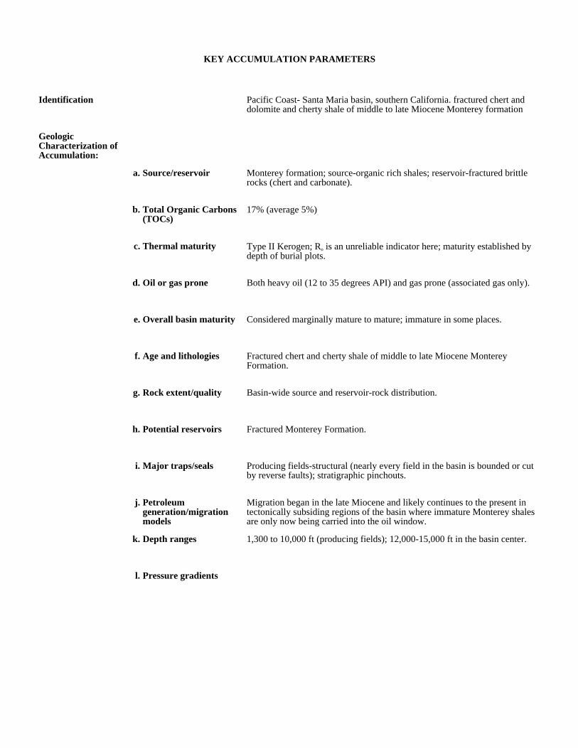
KEY ACCUMULATION PARAMETERS
Identification Pacific Coast- Santa Maria basin, southern California. fractured chert and dolomite and cherty shale of middle to late Miocene Monterey formation
Geologic Characterization of Accumulation:
a. Source/reservoir Monterey formation; source-organic rich shales; reservoir-fractured brittle rocks (chert and carbonate).
b. Total Organic Carbons (TOCs)
17% (average 5%)
c. Thermal maturity Type II Kerogen; Ro is an unreliable indicator here; maturity established by depth of burial plots.
d. Oil or gas prone Both heavy oil (12 to 35 degrees API) and gas prone (associated gas only).
e. Overall basin maturity Considered marginally mature to mature; immature in some places.
f. Age and lithologies Fractured chert and cherty shale of middle to late Miocene Monterey Formation.
g. Rock extent/quality Basin-wide source and reservoir-rock distribution.
h. Potential reservoirs Fractured Monterey Formation.
i. Major traps/seals Producing fields-structural (nearly every field in the basin is bounded or cut by reverse faults); stratigraphic pinchouts.
j. Petroleum generation/migration models
Migration began in the late Miocene and likely continues to the present in tectonically subsiding regions of the basin where immature Monterey shales are only now being carried into the oil window.
k. Depth ranges 1,300 to 10,000 ft (producing fields); 12,000-15,000 ft in the basin center.
l. Pressure gradients
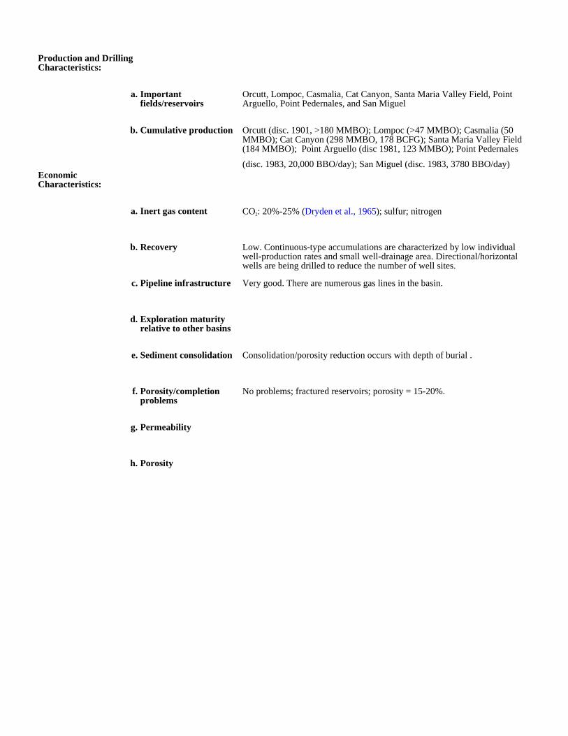
Production and Drilling Characteristics:
a. Important fields/reservoirs
Orcutt, Lompoc, Casmalia, Cat Canyon, Santa Maria Valley Field, Point Arguello, Point Pedernales, and San Miguel
b. Cumulative production Orcutt (disc. 1901, >180 MMBO); Lompoc (>47 MMBO); Casmalia (50 MMBO); Cat Canyon (298 MMBO, 178 BCFG); Santa Maria Valley Field (184 MMBO); Point Arguello (disc 1981, 123 MMBO); Point Pedernales
(disc. 1983, 20,000 BBO/day); San Miguel (disc. 1983, 3780 BBO/day)Economic Characteristics:
a. Inert gas content CO2: 20%-25% (Dryden et al., 1965); sulfur; nitrogen
b. Recovery Low. Continuous-type accumulations are characterized by low individual well-production rates and small well-drainage area. Directional/horizontal wells are being drilled to reduce the number of well sites.
c. Pipeline infrastructure Very good. There are numerous gas lines in the basin.
d. Exploration maturity relative to other basins
e. Sediment consolidation Consolidation/porosity reduction occurs with depth of burial .
f. Porosity/completion problems
No problems; fractured reservoirs; porosity = 15-20%.
g. Permeability
h. Porosity
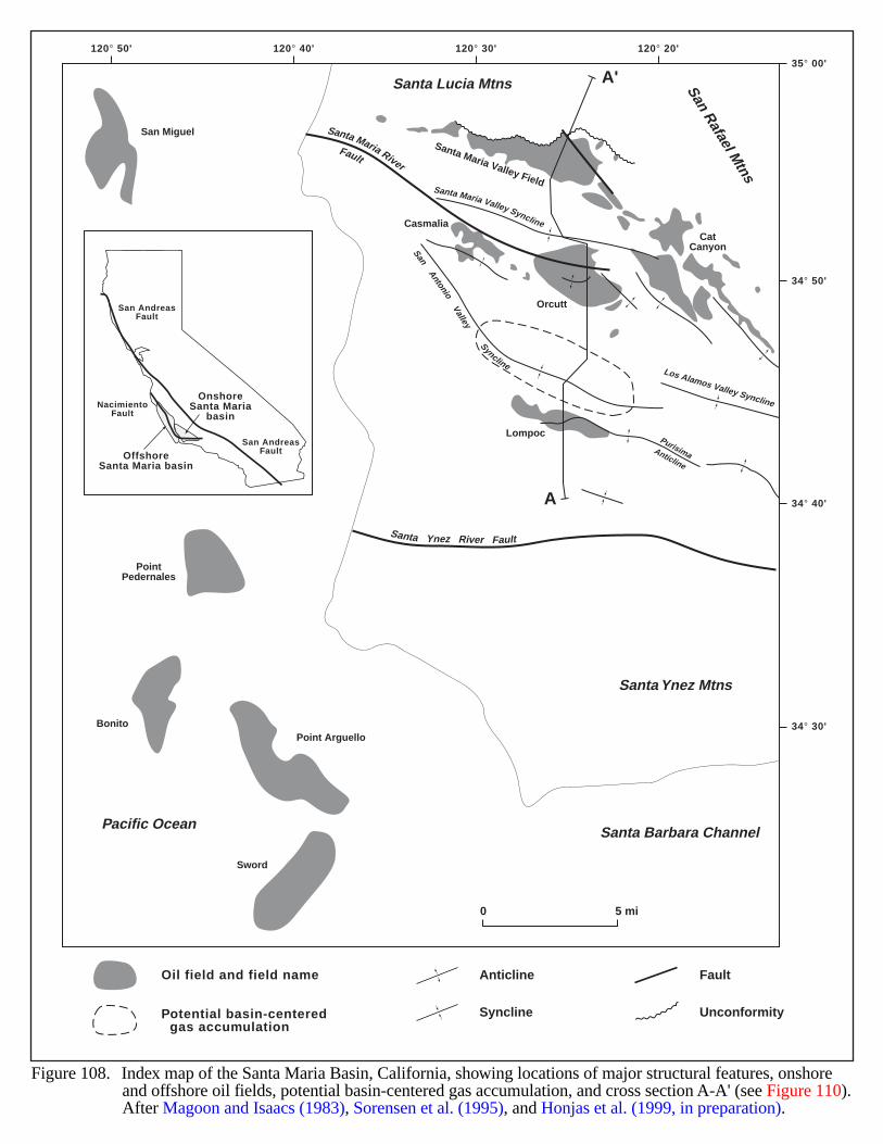
120° 30'120° 40'120° 50' 120° 20'35° 00'
34° 50'
34° 40'
34° 30'
A
A'
Lompoc
PointPedernales
San Miguel
BonitoPoint Arguello
Sword
Casmalia
Orcutt
Santa Maria Valley Field
CatCanyonSan
AntonioValley
Syncline
Santa Maria Valley Syncline
Los Alamos Valley Syncline
PurisimaAnticline
San Rafael M
tns
Santa Ynez Mtns
Pacific Ocean Santa Barbara Channel
Santa Lucia Mtns
Santa Ynez River Fault
Santa Maria RiverFault
OffshoreSanta Maria basin
OnshoreSanta Maria
basinNacimiento
Fault
San AndreasFault
San AndreasFault
Anticline
Figure 108. Index map of the Santa Maria Basin, California, showing locations of major structural features, onshoreand offshore oil fields, potential basin-centered gas accumulation, and cross section A-A' (see Figure 110).After Magoon and Isaacs (1983), Sorensen et al. (1995), and Honjas et al. (1999, in preparation).
0 5 mi
Oil field and field name
Potential basin-centered gas accumulation
Fault
Syncline Unconformity
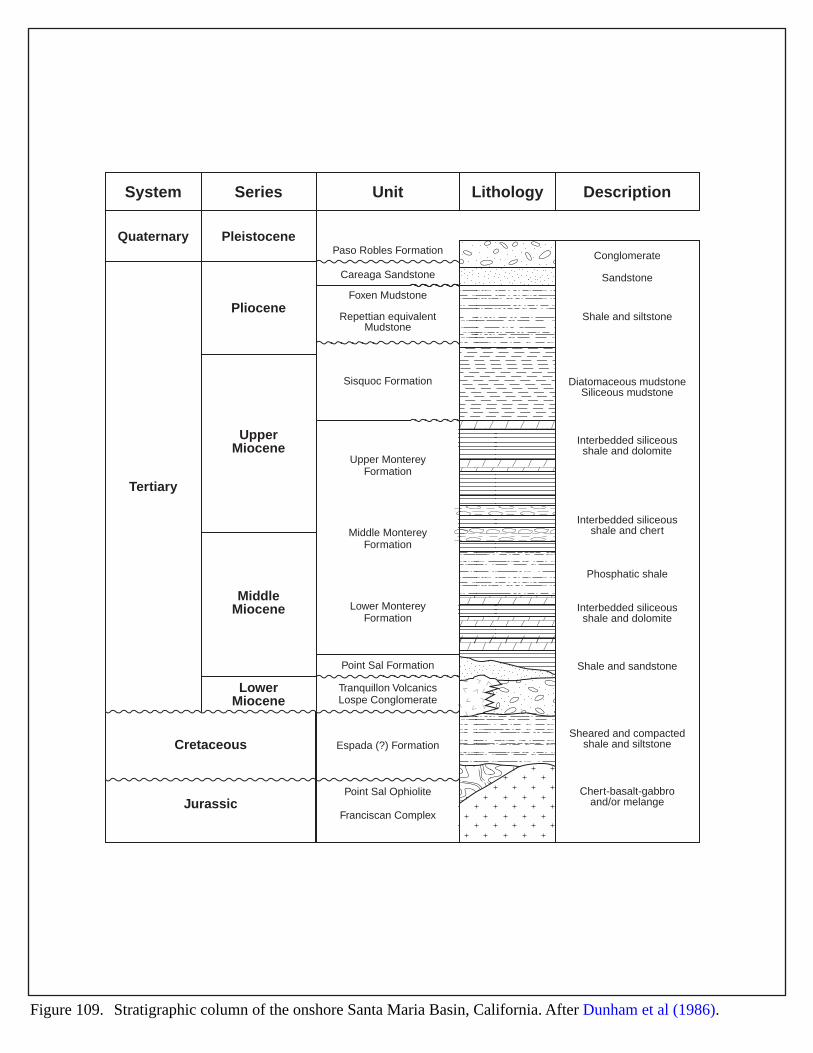
System
Quaternary
Tertiary
PleistocenePaso Robles Formation Conglomerate
Sandstone
Shale and siltstone
Shale and sandstone
Sheared and compactedshale and siltstone
Chert-basalt-gabbroand/or melange
Diatomaceous mudstoneSiliceous mudstone
Interbedded siliceousshale and dolomite
Interbedded siliceousshale and dolomite
Interbedded siliceousshale and chert
Phosphatic shale
Careaga Sandstone
Foxen Mudstone
Repettian equivalentMudstone
Sisquoc Formation
Upper MontereyFormation
Middle MontereyFormation
Lower MontereyFormation
Point Sal Formation
Espada (?) Formation
Point Sal Ophiolite
Franciscan Complex
Tranquillon VolcanicsLospe Conglomerate
Pliocene
UpperMiocene
MiddleMiocene
LowerMiocene
Cretaceous
Jurassic
Series Unit DescriptionLithology
Figure 109. Stratigraphic column of the onshore Santa Maria Basin, California. After Dunham et al (1986).
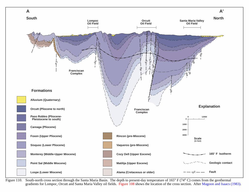
Figure 110. South-north cross section through the Santa Maria Basin. The depth to present-day temperature of 165° F (74° C) comes from the geothermalgradients for Lompoc, Orcutt and Santa Maria Valley oil fields. Figure 108 shows the location of the cross section. After Magoon and Isaacs (1983).
LompocOil Field
OrcuttOil Field
Santa Maria ValleyOil Field
South
A
North
A'
Alluvium (Quaternary)
Orcutt (Pliocene to north)
Paso Robles (Pliocene- Pleistocene to south)
Careaga (Pliocene)
Foxen (Upper Pliocene)
Sisquoc (Lower Pliocene)
Monterey (Middle-Upper Miocene)
Rincon (pre-Miocene)
165° F Isotherm
Geologic contact
Vaqueros (pre-Miocene)
Cozy Dell (Upper Eocene)
Fault
Matilija (Upper Eocene)
Alama (Cretaceous or older)
Point Sal (Middle Miocene)
Lospe (Lower Miocene)
FranciscanComplex
FranciscanComplex
Scale(in feet)
00 12000
1000
2000
3000
Formations
Explanation
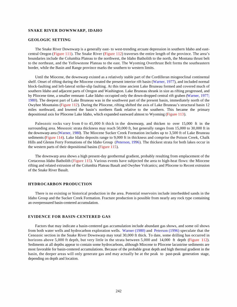
242
SNAKE RIVER DOWNWARP, IDAHO
GEOLOGIC SETTING
The Snake River Downwarp is a generally east- to west-trending arcuate depression in southern Idaho and east-central Oregon (Figure 111). The Snake River (Figure 112) traverses the entire length of the province. The area’sboundaries include the Columbia Plateau to the northwest, the Idaho Batholith to the north, the Montana thrust beltto the northeast, and the Yellowstone Plateau to the east. The Wyoming Overthrust Belt forms the southeasternborder, while the Basin and Range province marks the southern to western limits.
Until the Miocene, the downwarp existed as a relatively stable part of the Cordilleran miogeoclinal continentalshelf. Onset of rifting during the Miocene created the present interior rift basin (Warner, 1977), and included normalblock-faulting and left-lateral strike-slip faulting. At this time ancient Lake Bruneau formed and covered much ofsouthern Idaho and adjacent parts of Oregon and Washington. Lake Bruneau shrank in size as rifting progressed, andby Pliocene time, a smaller remnant–Lake Idaho–occupied only the down-dropped central rift graben (Warner, 1977;1980). The deepest part of Lake Bruneau was in the southwest part of the present basin, immediately north of theOwyhee Mountains (Figure 112). During the Pliocene, rifting shifted the axis of Lake Bruneau’s structural basin 12miles northward, and lowered the basin’s northern flank relative to the southern. This became the primarydepositional axis for Pliocene Lake Idaho, which expanded eastward almost to Wyoming (Figure 113).
Paleozoic rocks vary from 0 to 45,000 ft thick in the downwarp, and thicken to over 15,000 ft in thesurrounding area. Mesozoic strata thickness may reach 50,000 ft, but generally ranges from 15,000 to 30,000 ft inthe downwarp area (Warner, 1980). The Miocene Sucker Creek Formation includes up to 3,500 ft of Lake Bruneausediments (Figure 114). Lake Idaho deposits range to 9,000 ft in thickness and comprise the Poison Creek, ChalkHills and Glenns Ferry Formations of the Idaho Group (Peterson, 1996). The thickest strata for both lakes occur inthe western parts of their depositional basins (Figure 115).
The downwarp area shows a high present-day geothermal gradient, probably resulting from emplacement of theCretaceous Idaho Batholith (Figure 115). Various events have subjected the area to high-heat flows: the Miocenerifting and related extrusion of the Columbia Plateau Basalt and Owyhee Volcanics; and Pliocene to Recent extrusionof the Snake River Basalt.
HYDROCARBON PRODUCTION
There is no existing or historical production in the area. Potential reservoirs include interbedded sands in theIdaho Group and the Sucker Creek Formation. Fracture production is possible from nearly any rock type containingan overpressured basin-centered accumulation.
EVIDENCE FOR BASIN-CENTERED GAS
Factors that may indicate a basin-centered gas accumulation include abundant gas shows, and some oil showsfrom both water wells and hydrocarbon exploration wells. Warner (1980) and Peterson (1996) speculate that theCenozoic section in the Snake River Downwarp may total 30,000 ft thick. To date, some drilling has occurred inhorizons above 5,000 ft depth, but very little in the strata between 5,000 and 14,000 ft depth (Figure 112).Sediments at all depths appear to contain some hydrocarbons, although Miocene to Pliocene lacustrine sediments aremost favorable for basin-centered accumulations. Because of the probable great depth and high thermal gradient in thebasin, the deeper areas will only generate gas and may actually be at the peak to past-peak generation stage,depending on depth and location.
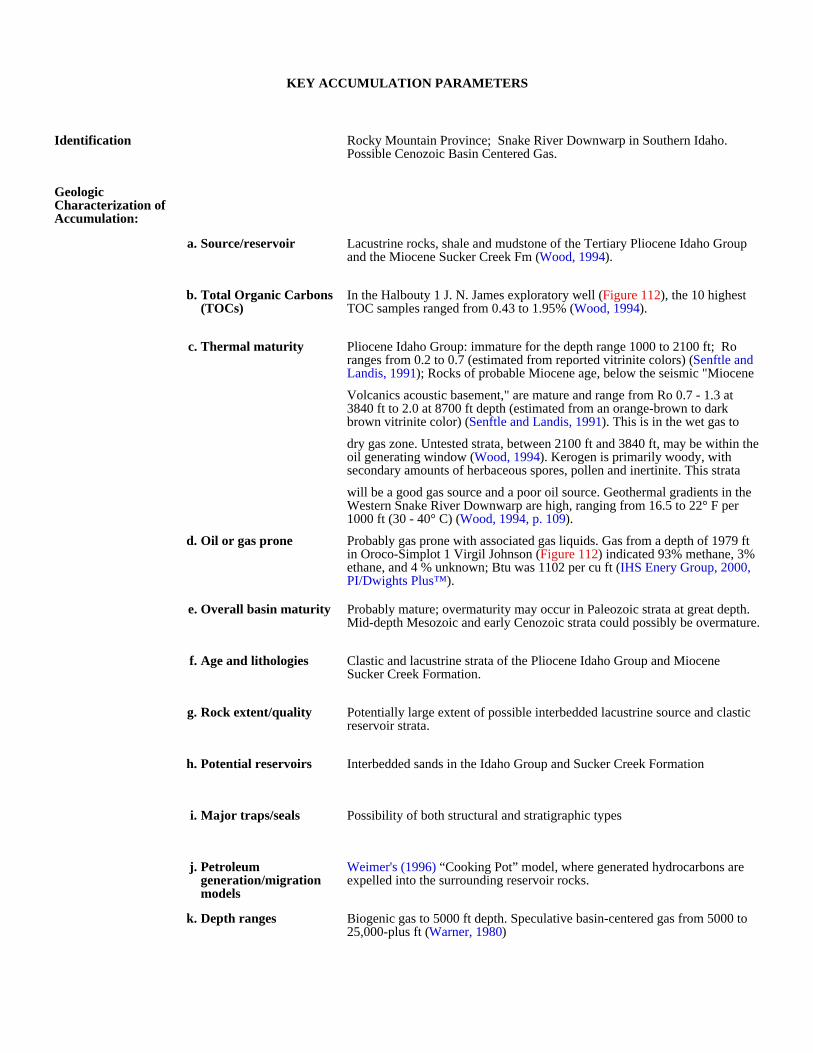
KEY ACCUMULATION PARAMETERS
Identification Rocky Mountain Province; Snake River Downwarp in Southern Idaho. Possible Cenozoic Basin Centered Gas.
Geologic Characterization of Accumulation:
a. Source/reservoir Lacustrine rocks, shale and mudstone of the Tertiary Pliocene Idaho Group and the Miocene Sucker Creek Fm (Wood, 1994).
b. Total Organic Carbons (TOCs)
In the Halbouty 1 J. N. James exploratory well (Figure 112), the 10 highest TOC samples ranged from 0.43 to 1.95% (Wood, 1994).
c. Thermal maturity Pliocene Idaho Group: immature for the depth range 1000 to 2100 ft; Ro ranges from 0.2 to 0.7 (estimated from reported vitrinite colors) (Senftle and Landis, 1991); Rocks of probable Miocene age, below the seismic "Miocene
Volcanics acoustic basement," are mature and range from Ro 0.7 - 1.3 at 3840 ft to 2.0 at 8700 ft depth (estimated from an orange-brown to dark brown vitrinite color) (Senftle and Landis, 1991). This is in the wet gas to
dry gas zone. Untested strata, between 2100 ft and 3840 ft, may be within the oil generating window (Wood, 1994). Kerogen is primarily woody, with secondary amounts of herbaceous spores, pollen and inertinite. This strata
will be a good gas source and a poor oil source. Geothermal gradients in the Western Snake River Downwarp are high, ranging from 16.5 to 22° F per 1000 ft (30 - 40° C) (Wood, 1994, p. 109).
d. Oil or gas prone Probably gas prone with associated gas liquids. Gas from a depth of 1979 ft in Oroco-Simplot 1 Virgil Johnson (Figure 112) indicated 93% methane, 3% ethane, and 4 % unknown; Btu was 1102 per cu ft (IHS Enery Group, 2000, PI/Dwights Plus™).
e. Overall basin maturity Probably mature; overmaturity may occur in Paleozoic strata at great depth. Mid-depth Mesozoic and early Cenozoic strata could possibly be overmature.
f. Age and lithologies Clastic and lacustrine strata of the Pliocene Idaho Group and Miocene Sucker Creek Formation.
g. Rock extent/quality Potentially large extent of possible interbedded lacustrine source and clastic reservoir strata.
h. Potential reservoirs Interbedded sands in the Idaho Group and Sucker Creek Formation
i. Major traps/seals Possibility of both structural and stratigraphic types
j. Petroleum generation/migration models
Weimer's (1996) “Cooking Pot” model, where generated hydrocarbons are expelled into the surrounding reservoir rocks.
k. Depth ranges Biogenic gas to 5000 ft depth. Speculative basin-centered gas from 5000 to 25,000-plus ft (Warner, 1980)
l. Pressure gradients 0.45 psi/ft (±0.06 psi/ft) for shallow objectives. Deeper objectives are possibly overpressured.
Production and Drilling Characteristics:
a. Important fields/reservoirs
none
b. Cumulative production none
Economic Characteristics:
a. Inert gas content Less than 5%.
b. Recovery
c. Pipeline infrastructure A single 24-inch pipeline passes through the area paralleling Interstate 84. Several small lateral lines serve the towns surrounding Boise, Idaho. A major trunk line runs from the southwest corner of Idaho to Reno, Nevada.
d. Exploration maturity relative to other basins
Immature.
e. Sediment consolidation Poorly consolidated rocks may exist in the shallower parts of the basin.
f. Porosity/completion problems
Low porosity and permeability may be a problem, at least in underpressured or normally pressured areas.
g. Permeability
h. Porosity
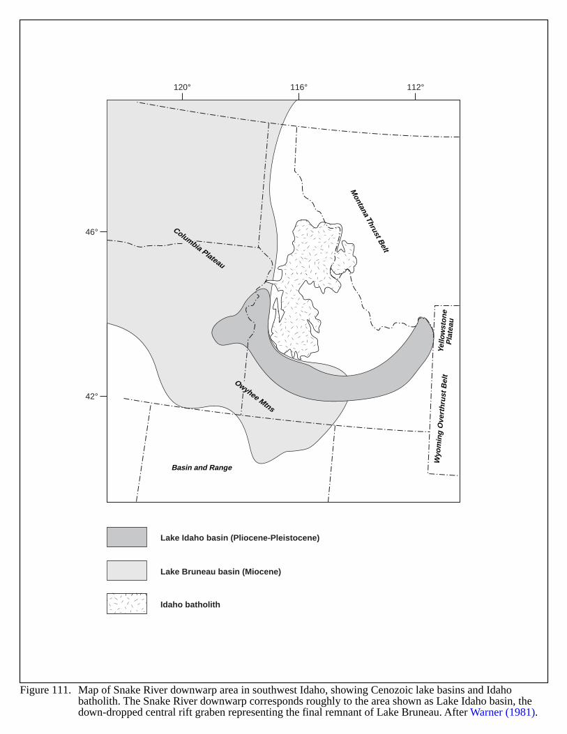
Owyhee Mtns
Columbia Plateau
Yello
wst
on
eP
late
au
Wyo
min
g O
vert
hru
st B
elt
Montana Thrust B
elt
Basin and Range
Lake Idaho basin (Pliocene-Pleistocene)
Lake Bruneau basin (Miocene)
Idaho batholith
Figure 111. Map of Snake River downwarp area in southwest Idaho, showing Cenozoic lake basins and Idaho batholith. The Snake River downwarp corresponds roughly to the area shown as Lake Idaho basin, the down-dropped central rift graben representing the final remnant of Lake Bruneau. After Warner (1981).
116°120° 112°
46°
42°
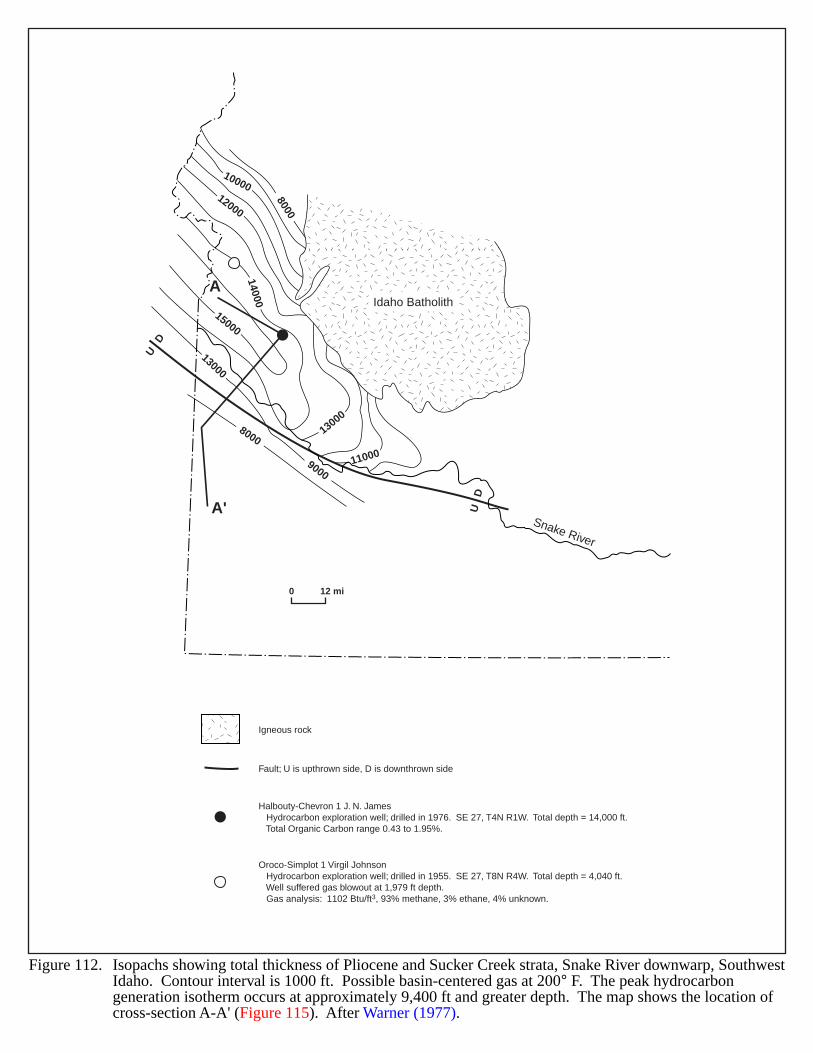
8000
1000012000
14000
15000
13000
13000
11000
8000
9000
A
A'Snake River
UD
UD
Idaho Batholith
0 12 mi
Figure 112. Isopachs showing total thickness of Pliocene and Sucker Creek strata, Snake River downwarp, SouthwestIdaho. Contour interval is 1000 ft. Possible basin-centered gas at 200° F. The peak hydrocarbon generation isotherm occurs at approximately 9,400 ft and greater depth. The map shows the location of cross-section A-A' (Figure 115). After Warner (1977).
Halbouty-Chevron 1 J. N. James Hydrocarbon exploration well; drilled in 1976. SE 27, T4N R1W. Total depth = 14,000 ft. Total Organic Carbon range 0.43 to 1.95%.
Oroco-Simplot 1 Virgil Johnson Hydrocarbon exploration well; drilled in 1955. SE 27, T8N R4W. Total depth = 4,040 ft. Well suffered gas blowout at 1,979 ft depth. Gas analysis: 1102 Btu/ft3, 93% methane, 3% ethane, 4% unknown.
Fault; U is upthrown side, D is downthrown side
Igneous rock
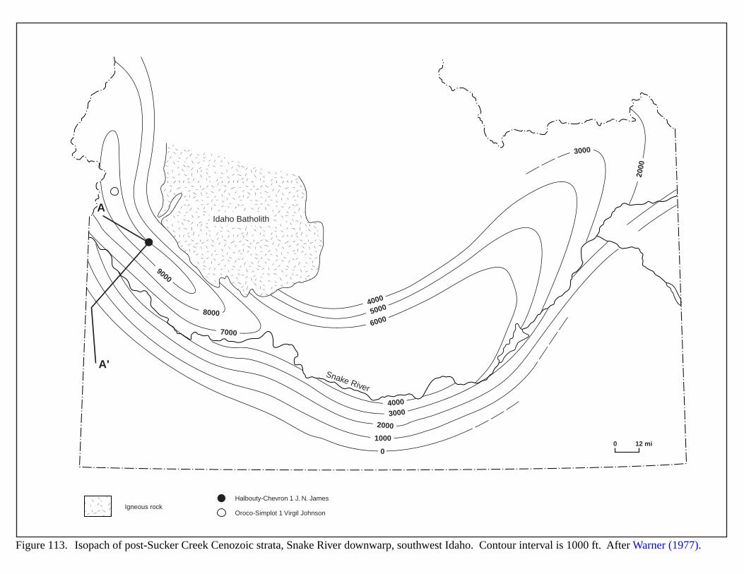
1000
0
3000
3000
4000
60005000
4000
2000
7000
8000
9000
2000
A
A'Snake River
Idaho Batholith
0 12 mi
Figure 113. Isopach of post-Sucker Creek Cenozoic strata, Snake River downwarp, southwest Idaho. Contour interval is 1000 ft. After Warner (1977).
Halbouty-Chevron 1 J. N. JamesIgneous rock
Oroco-Simplot 1 Virgil Johnson
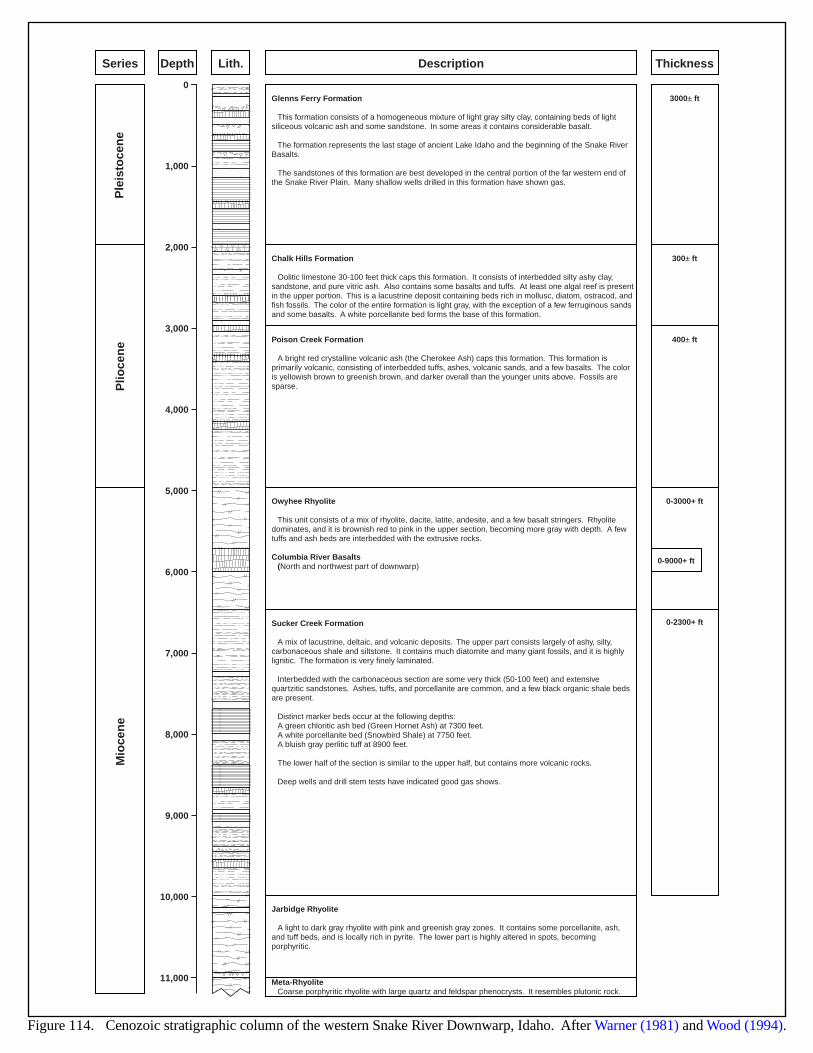
3000± ft
300± ft
400± ft
0-3000+ ft
0-9000+ ft
0-2300+ ft
0
1,000
2,000
3,000
4,000
5,000
6,000
7,000
8,000
9,000
10,000
11,000
Ple
isto
cen
eP
lioce
ne
Mio
cen
e
Glenns Ferry Formation
This formation consists of a homogeneous mixture of light gray silty clay, containing beds of light siliceous volcanic ash and some sandstone. In some areas it contains considerable basalt.
The formation represents the last stage of ancient Lake Idaho and the beginning of the Snake RiverBasalts.
The sandstones of this formation are best developed in the central portion of the far western end ofthe Snake River Plain. Many shallow wells drilled in this formation have shown gas.
Chalk Hills Formation
Oolitic limestone 30-100 feet thick caps this formation. It consists of interbedded silty ashy clay,sandstone, and pure vitric ash. Also contains some basalts and tuffs. At least one algal reef is presentin the upper portion. This is a lacustrine deposit containing beds rich in mollusc, diatom, ostracod, andfish fossils. The color of the entire formation is light gray, with the exception of a few ferruginous sandsand some basalts. A white porcellanite bed forms the base of this formation.
Poison Creek Formation
A bright red crystalline volcanic ash (the Cherokee Ash) caps this formation. This formation isprimarily volcanic, consisting of interbedded tuffs, ashes, volcanic sands, and a few basalts. The coloris yellowish brown to greenish brown, and darker overall than the younger units above. Fossils aresparse.
Owyhee Rhyolite
This unit consists of a mix of rhyolite, dacite, latite, andesite, and a few basalt stringers. Rhyolitedominates, and it is brownish red to pink in the upper section, becoming more gray with depth. A fewtuffs and ash beds are interbedded with the extrusive rocks.
Columbia River Basalts(North and northwest part of downwarp)
Sucker Creek Formation
A mix of lacustrine, deltaic, and volcanic deposits. The upper part consists largely of ashy, silty,carbonaceous shale and siltstone. It contains much diatomite and many giant fossils, and it is highlylignitic. The formation is very finely laminated.
Interbedded with the carbonaceous section are some very thick (50-100 feet) and extensivequartzitic sandstones. Ashes, tuffs, and porcellanite are common, and a few black organic shale bedsare present.
Distinct marker beds occur at the following depths:A green chloritic ash bed (Green Hornet Ash) at 7300 feet.A white porcellanite bed (Snowbird Shale) at 7750 feet.A bluish gray perlitic tuff at 8900 feet.
The lower half of the section is similar to the upper half, but contains more volcanic rocks.
Deep wells and drill stem tests have indicated good gas shows.
Jarbidge Rhyolite
A light to dark gray rhyolite with pink and greenish gray zones. It contains some porcellanite, ash,and tuff beds, and is locally rich in pyrite. The lower part is highly altered in spots, becomingporphyritic.
Meta-RhyoliteCoarse porphyritic rhyolite with large quartz and feldspar phenocrysts. It resembles plutonic rock.
Series Depth Lith. Description Thickness
Figure 114. Cenozoic stratigraphic column of the western Snake River Downwarp, Idaho. After Warner (1981) and Wood (1994).
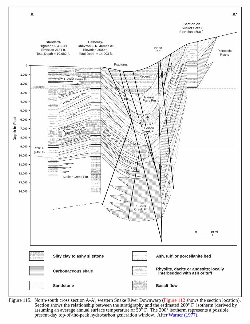
Columbia River
Basalt Section
Columbia River
Basalt Section
Poison Creek Fm Pois
on C
reek
Fm
Glenns Ferry Fm
Sucker Creek Fm
Jarb
idge
Rhy
olite
Suc
ker C
reek
Fm
SuckerCreek Fm
PoisonCreek Fm
ChalkHills Fm
GlennsFerry Fm
Recent
IdahoRift
Fractures
Chalk Hills Fm
Ow
yhee
Rhy
olite
1,000
Sea level
200° F(9400 ft)
0
2,000
3,000
4,000
5,000
6,000
7,000
8,000
9,000
10,000
11,000
12,000
13,000
14,000
Dep
th in
Fee
t
Standard-Highland L & L #1Elevation 2631 ft.
Total Depth = 10,682 ft.
Halbouty-Chevron J. N. James #1
Elevation 2500 ft.Total Depth = 14,003 ft.
Section onSucker Creek
Elevation 4500 ft.
PaleozoicRocks
A A'
Figure 115. North-south cross section A-A', western Snake River Downwarp (Figure 112 shows the section location).Section shows the relationship between the stratigraphy and the estimated 200° F isotherm (derived by assuming an average annual surface temperature of 50° F. The 200° isotherm represents a possible present-day top-of-the-peak hydrocarbon generation window. After Warner (1977).
Silty clay to ashy siltstone
Carbonaceous shale
Sandstone
Ash, tuff, or porcellanite bed
Rhyolite, dacite or andesite; locally interbedded with ash or tuff
Basalt flow
0 10 mi
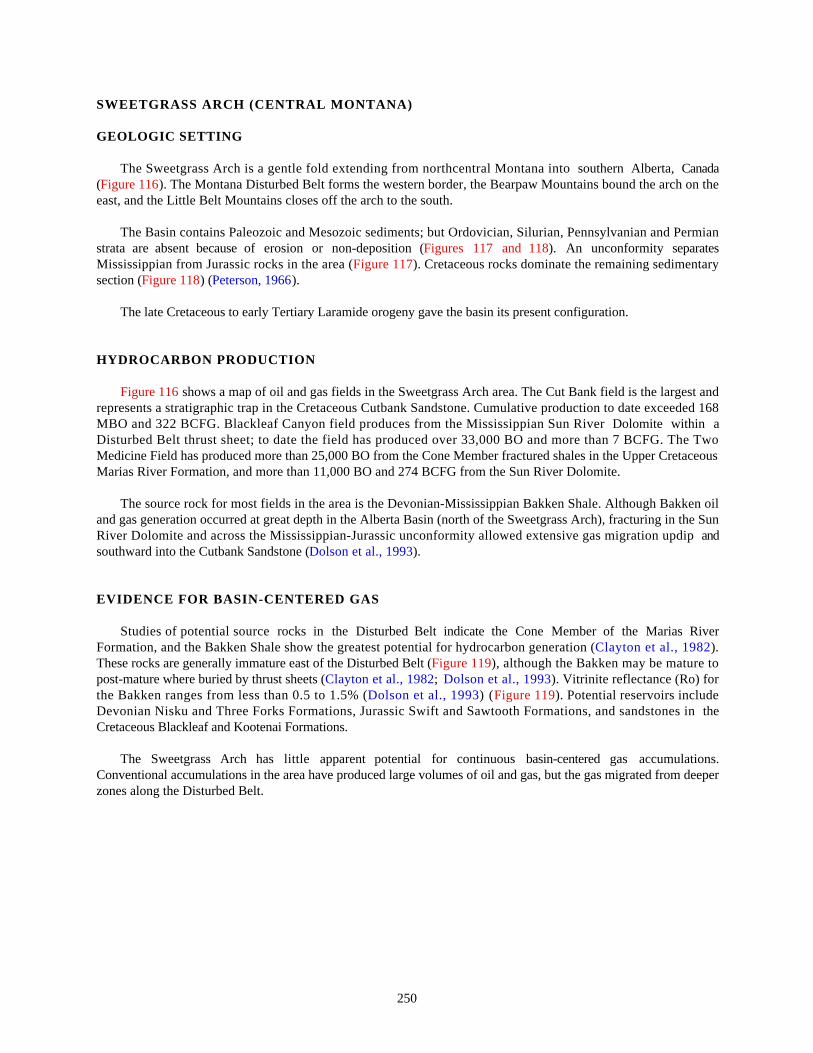
250
SWEETGRASS ARCH (CENTRAL MONTANA)
GEOLOGIC SETTING
The Sweetgrass Arch is a gentle fold extending from northcentral Montana into southern Alberta, Canada(Figure 116). The Montana Disturbed Belt forms the western border, the Bearpaw Mountains bound the arch on theeast, and the Little Belt Mountains closes off the arch to the south.
The Basin contains Paleozoic and Mesozoic sediments; but Ordovician, Silurian, Pennsylvanian and Permianstrata are absent because of erosion or non-deposition (Figures 117 and 118). An unconformity separatesMississippian from Jurassic rocks in the area (Figure 117). Cretaceous rocks dominate the remaining sedimentarysection (Figure 118) (Peterson, 1966).
The late Cretaceous to early Tertiary Laramide orogeny gave the basin its present configuration.
HYDROCARBON PRODUCTION
Figure 116 shows a map of oil and gas fields in the Sweetgrass Arch area. The Cut Bank field is the largest andrepresents a stratigraphic trap in the Cretaceous Cutbank Sandstone. Cumulative production to date exceeded 168MBO and 322 BCFG. Blackleaf Canyon field produces from the Mississippian Sun River Dolomite within aDisturbed Belt thrust sheet; to date the field has produced over 33,000 BO and more than 7 BCFG. The TwoMedicine Field has produced more than 25,000 BO from the Cone Member fractured shales in the Upper CretaceousMarias River Formation, and more than 11,000 BO and 274 BCFG from the Sun River Dolomite.
The source rock for most fields in the area is the Devonian-Mississippian Bakken Shale. Although Bakken oiland gas generation occurred at great depth in the Alberta Basin (north of the Sweetgrass Arch), fracturing in the SunRiver Dolomite and across the Mississippian-Jurassic unconformity allowed extensive gas migration updip andsouthward into the Cutbank Sandstone (Dolson et al., 1993).
EVIDENCE FOR BASIN-CENTERED GAS
Studies of potential source rocks in the Disturbed Belt indicate the Cone Member of the Marias RiverFormation, and the Bakken Shale show the greatest potential for hydrocarbon generation (Clayton et al., 1982).These rocks are generally immature east of the Disturbed Belt (Figure 119), although the Bakken may be mature topost-mature where buried by thrust sheets (Clayton et al., 1982; Dolson et al., 1993). Vitrinite reflectance (Ro) forthe Bakken ranges from less than 0.5 to 1.5% (Dolson et al., 1993) (Figure 119). Potential reservoirs includeDevonian Nisku and Three Forks Formations, Jurassic Swift and Sawtooth Formations, and sandstones in theCretaceous Blackleaf and Kootenai Formations.
The Sweetgrass Arch has little apparent potential for continuous basin-centered gas accumulations.Conventional accumulations in the area have produced large volumes of oil and gas, but the gas migrated from deeperzones along the Disturbed Belt.
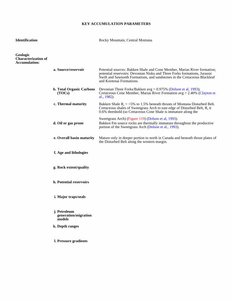
KEY ACCUMULATION PARAMETERS
Identification Rocky Mountain, Central Montana
Geologic Characterization of Accumulation:
a. Source/reservoir Potential sources: Bakken Shale and Cone Member, Marias River formation; potential reservoirs: Devonian Nisku and Three Forks formations, Jurassic Swift and Sawtooth Formations, and sandstones in the Cretaceous Blackleaf and Kootenai Formations.
b. Total Organic Carbons (TOCs)
Devonian Three Forks/Bakken avg = 0.975% (Dolson et al, 1993); Cretaceous Cone Member, Marias River Formation avg = 2.40% (Clayton et al., 1982).
c. Thermal maturity Bakken Shale Ro = <5% to 1.5% beneath thrusts of Montana Disturbed Belt. Cretaceous shales of Sweetgrass Arch to east edge of Disturbed Belt, Ro ≤ 0.6% threshold (so Cretaceous Cone Shale is immature along the
Sweetgrass Arch) (Figure 119) (Dolson et al, 1993).d. Oil or gas prone Bakken Fm source rocks are thermally immature throughout the productive
portion of the Sweetgrass Arch (Dolson et al., 1993).
e. Overall basin maturity Mature only in deeper portion to north in Canada and beneath thrust plates of the Disturbed Belt along the western margin.
f. Age and lithologies
g. Rock extent/quality
h. Potential reservoirs
i. Major traps/seals
j. Petroleum generation/migration models
k. Depth ranges
l. Pressure gradients

Production and Drilling Characteristics:
a. Important fields/reservoirs
b. Cumulative production
Economic Characteristics:
a. Inert gas content
b. Recovery
c. Pipeline infrastructure Good near conventional fields.
d. Exploration maturity relative to other basins
e. Sediment consolidation
f. Porosity/completion problems
g. Permeability
h. Porosity
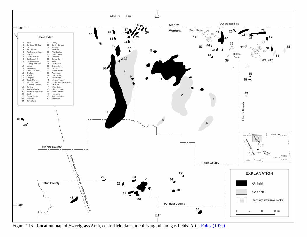
HelenaLittle BeltMtns
Montana D
isturbed Belt
Montana
Idaho
Alberta Saskatchewan
Wyoming
Sweetgrass A
rch
Alberta
Montana
Toole County
Pondera County
Teton County
Glacier County
Lib
erty
Co
un
ty
Approxim
ate East Lim
it of Montana D
isturbed Belt
Figure 116. Location map of Sweetgrass Arch, central Montana, identifying oil and gas fields. After Foley (1972).
Sweetgrass Hills
Alber ta Basin
MiddleButte
West Butte
East Butte
1514
13
12
11
7
9
9
5
40
41
42
43
44
46
47 45
2828
28
29
30
32
31
3738
39
33
34
35
35
36
1
23
4
24
25
2623
22 2323
23
23
27
6
16
1717
18 19
20
21
10
8
48
48
49
123456789
1011121314151617
18192021222324
KevinSunburst-ShelbyDevon"B" SquareRattlesnake CouleeMariasCut Bank GasCut Bank OilDahlquist North Dahlquist SouthLanderMcGuinessNorth Cut BankBradleyBlackfootReaganSouth DarlingRed Creek & Graben CouleeDarlingMoulton PoolsBorder-Red CouleeCobbGypsy BasinPonderaBannatyne
25262728293031323334353637383940414243444546474849
BradySouth ConradMidwayWhitlashFlat CouleeLaird CreekBlackjackBears DenKeithEast KeithGrandviewUtopiaMiddle ButteArch ApexGold ButteBertheloteMiners CouleeFred & George CreekPrichardWest ButteKicking HorseBow & ArrowHay LakeTwo MedicineBlackleaf
Field Index
EXPLANATION
Oil field
Gas field
Tertiary intrusive rocks
0 5 10 15 mi
112°
112°
48°
49°
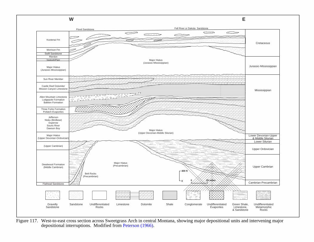
W E
Kootenai Fm
Flood Sandstone Fall River or Dakota Sandstone
Cretaceous
Jurassic-Mississippian
Mississippian
GravellySandstone
Sandstone UndifferentiatedRocks
Limestone Dolomite Shale Conglomerate UndifferentiatedEvaporites
Green Shale,Limestone,
& Sandstone
UndifferentiatedMetamorphic
Rocks
Lower Devonian-Upper& Middle Silurian
Lower Silurian
Upper Ordovician
Upper Cambrian
Cambrian-Precambrian
Morrison Fm
Swift SandstoneRierdon
Belt Rocks(Precambrian)
Sawtooth/Piper
Major Hiatus(Jurassic-Mississippian)
Major Hiatus(Jurassic-Mississippian)
Major Hiatus(Precambrian)
Major Hiatus(Upper Devonian-Middle Silurian)
Major Hiatus(Upper Devonian-Ordovician)
Flathead Sandstone
Deadwood Formation(Middle Cambrian)
(Upper Cambrian)
Sun River Member
Castle Reef Dolomite/Mission Canyon Limestone
Allen Mountain LimestoneLodgepole Formation
Bakken Formation
Three Forks FormationPotlatch Evaporites
JeffersonNisku (Birdbear)
DuperowSouris RiverDawson Boy
400 ft
0 0 25 miles
Figure 117. West-to-east cross section across Sweetgrass Arch in central Montana, showing major depositional units and intervening major depositional interruptions. Modified from Peterson (1966).
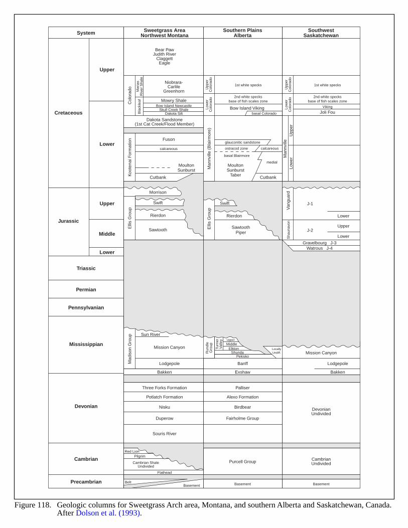
Sweetgrass AreaNorthwest MontanaSystem Southern Plains
AlbertaSouthwest
Saskatchewan
Bear PawJudith River
ClaggettEagle
Dakota Sandstone(1st Cat Creek/Flood Member)
Bakken
Three Forks Formation
Potlatch Formation
Nisku
Duperow
Palliser
Alexo Formation
Birdbear DevonianUndivided
CambrianUndivided
Fairholme Group
Purcell Group
Souris River
Exshaw
Niobrara-Carlile
Greenhorn1st white specks
basal Colorado
basal Blairmore
glauconitic sandstone
ostracod zone calcareous
medial
Cutbank
Viking
Joli Fou
J-1
J-2
Gravelbourg J-3Watrous J-4
2nd white specksbase of fish scales zoneMowry Shale
Fuson
Cutbank
Morrison
calcareous
Bow Island Viking
Col
orad
oK
oote
nai F
orm
atio
n
Man
nvill
e (B
lair
mor
e)
Man
nvill
eU
pper
Upper
Cretaceous
Jurassic
Triassic
Permian
Pennsylvanian
Mississippian
Devonian
Cambrian
Precambrian
Upper
Middle
Lower
Lower
Low
er
Lower
Upper
Lower
Elli
s G
roup
Mad
ison
Gro
up
Elli
s G
roup
Van
guar
dS
haun
avon
Bow Island Newcastle
MoultonSunburst
MoultonSunburst
Taber
Skull Creek ShaleDakota SiltB
lack
leaf
Low
erC
olor
ado
Upp
erC
olor
ado
1st white specks
2nd white specksbase of fish scales zone
Low
erC
olor
ado
Upp
erC
olor
ado
Mar
ias
Riv
er S
hale
Swift
Rierdon
Sawtooth
Sun River
Mission CanyonMission Canyon
Lodgepole
Bakken
LodgepoleBanff
Upper
LocallyUndiff.
MiddleElkton
Shunda
Red LionPilgrim
Flathead
Basement Basement BasementBelt
Cambrian ShaleUndivided
Pekisko
Run
dle
Gro
up
Turn
erV
alle
y
Swift
Rierdon
SawtoothPiper
Figure 118. Geologic columns for Sweetgrass Arch area, Montana, and southern Alberta and Saskatchewan, Canada. After Dolson et al. (1993).
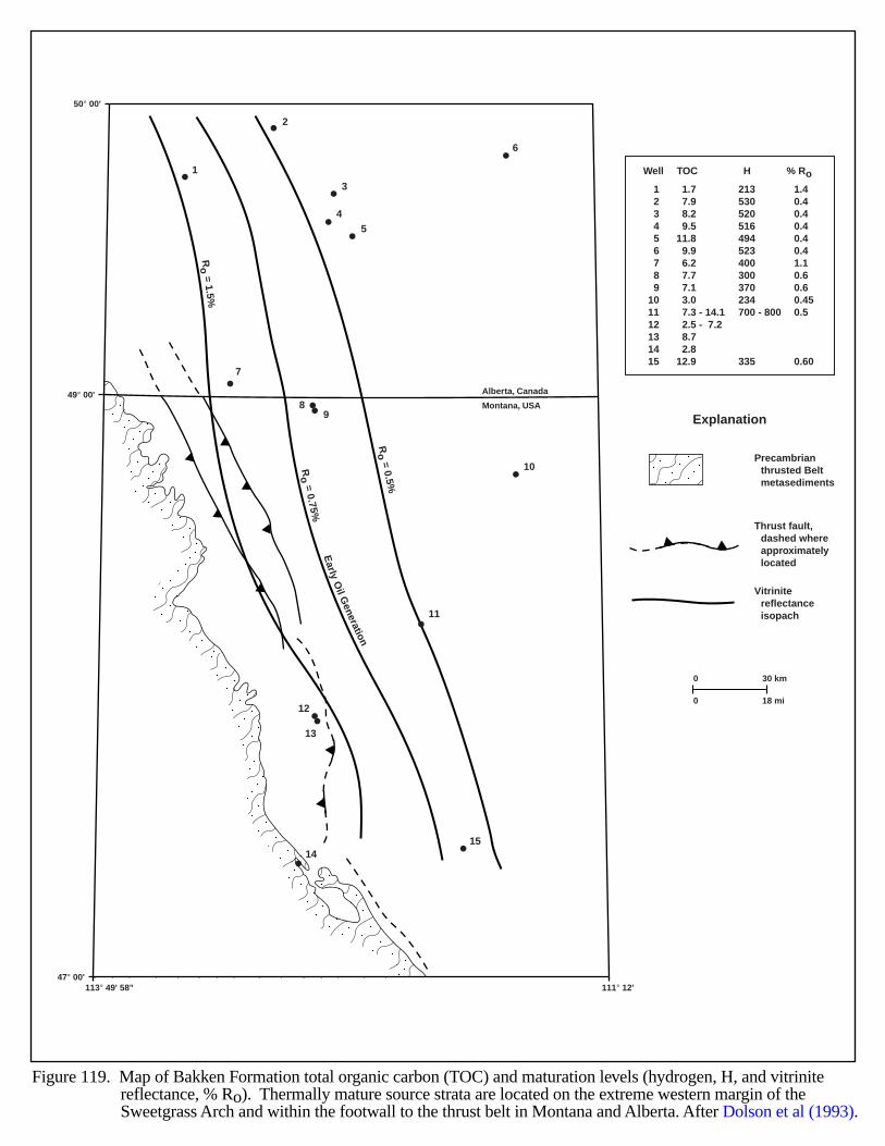
Alberta, Canada
Montana, USA
113° 49' 58" 111° 12' 47° 00'
50° 00'
49° 00'
Ro = 0.5%
Ro = 0.75%
Ro = 1.5%
1
7
89
10
11
12
13
1415
2
3
45
6
Early
Oil G
eneration
0
0
30 km
18 mi
Well
123456789
101112131415
H
213530520516494523400300370234700 - 800 335
TOC
1.77.98.29.5
11.89.96.27.77.13.07.3 - 14.12.5 - 7.28.72.8
12.9
% Ro
1.40.40.40.40.40.41.10.60.60.450.5 0.60
Thrust fault,dashed whereapproximatelylocated
Precambrianthrusted Beltmetasediments
Vitrinitereflectanceisopach
Explanation
Figure 119. Map of Bakken Formation total organic carbon (TOC) and maturation levels (hydrogen, H, and vitrinite reflectance, % Ro). Thermally mature source strata are located on the extreme western margin of theSweetgrass Arch and within the footwall to the thrust belt in Montana and Alberta. After Dolson et al (1993).

257
WASATCH PLATEAU
GEOLOGIC SETTING
The Wasatch Plateau is an 80 mi long by 25 mi wide uplift west of the San Rafael Swell in east-central Utah,within parts of Sanpete, Sevier, Emery and Carbon Counties, and lies sandwiched between Sanpete Valley to thewest and Castle Valley to the east (Figures 120 and 121). Structural features west of the Plateau include theGunnison Plateau and Wasatch Monocline (Figure 121). The Wasatch Plateau forms part of the central Utahtransition zone, between the Colorado Plateau to the east and the Basin and Range province to the west.
The Plateau’s history begins with Cretaceous synorogenic deposition of clastic sediments in a foreland basineast of the Cordillera. On the western periphery of the basin, local deposits of deltaic and paludal sediments alternatedwith deepwater mudstones deposited during several transgressive cycles (Figure 122). Eastward thrusting and upliftprobably began during the late Jurassic-early Eocene Sevier Orogeny (Neuhauser, 1988). Diapiric movements andextensional faulting occurred during the Cenozoic era. Figure 121 shows fault structure for the area.
Exposures of Quaternary alluvium, Tertiary sandstones and limestones, and Upper Cretaceous Mesaverde Groupsandstones, shales and coalbeds occur atop the Plateau. Figures 122 and 123 show the area’s stratigraphy.
HYDROCARBON PRODUCTION
Oil and gas production in the Wasatch Plateau occurs mostly from Cretaceous Ferron sandstones east of theJoe’s Valley Graben and west of the Ferron outcrop (Tripp. 1996). The Cretaceous Dakota Group and PermianKaibab Formation have had some minor production as well. The fields along the Plateau have produced over 158BCFG and 132 MBO since 1951.
On the eastern margin of the plateau, recent coalbed methane production from Ferron coals in Drunkards WashField (discovered in 1992) has sparked renewed interest in the area (Lamarre and Burns, 1997). Cumulative productionincluding coalbed methane exceeds 224 BCFG.
Production on the Wasatch Plateau has generally been from structural traps, probably enhanced by tectonicfracturing (Tripp, 1990).
EVIDENCE FOR BASIN-CENTERED GAS
Not enough evidence exists to determine if an overpressure cell encompassing the Cretaceous rocks occurs atdeeper drilling depths within the plateau. Production does occur from gas fields along the eastern plateau margin, butpressure gradients are very low (significant underpressure) and only range from 0.21 to 0.27 psi/ft. Also, the Ferronfield shows downdip water flows (recorded in Northwest Prod. Co. #1 Federal, NENE 29-19S-7E), which indicatesunderpressuring and a probable gas-water contact at depth. Additionally, drillstem tests in the vicinity of the plateaurecovered water, indicating normal to underpressuring in the lower Cretaceous sediments. Most wells showing waterare in close proximity to known mapped faults (Tripp, 1989). The high degree of tectonism and associated fracturingof the rocks may allow water to flow upward from the Paleozoic section or downward from Tertiary and Cretaceousrocks along the fault zones. If a “gas kitchen” once existed in this area, faulting may have breached it.
Exploration the central part of the Plateau has been rare and many townships remain untested. However, in 1996Cimarron Energy Corporation re-entered a 20,505 ft deep test well (Hanson Oil Corp.’s Maroni #1AX, 14-15S-3E);Cimarron completed two sidetracks within Tununk Shale at depths of 11,772 and 11,840 ft. Cumulative productionthrough June of 1999 was 369 BO and 425 MCF for this undesignated field (Utah Div. of Oil, Gas and Mining,1999). This significant show indicates a fractured shale play probably occurs on the Plateau.
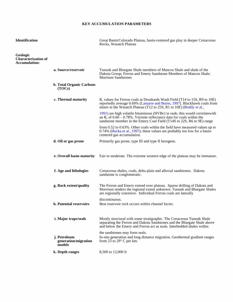
KEY ACCUMULATION PARAMETERS
Identification Great Basin/Colorado Plateau, basin-centered gas play in deeper Cretaceous Rocks, Wasatch Plateau
Geologic Characterization of Accumulation:
a. Source/reservoir Tununk and Bluegate Shale members of Mancos Shale and shale of the Dakota Group; Ferron and Emery Sandstone Members of Mancos Shale; Morrison Sandstones
b. Total Organic Carbons (TOCs)
c. Thermal maturity Ro values for Ferron coals at Drunkards Wash Field (T14 to 15S, R9 to 10E) reportedly average 0.69% (Lamarre and Burns, 1997). Blackhawk coals from mines in the Wasatch Plateau (T12 to 25S, R1 to 10E) (Bodily et al.,
1991) are high volatile bituminous (HVBc) in rank; this would correlatewith an Ro of 0.60 – 0.78%. Vitrinite reflectance data for coals within the sandstone member in the Emery Coal Field (T14S to 22S, R6 to 9E) range
from 0.52 to 0.63%. Other coals within the field have measured values up to 0.74% (Hucka et al., 1997); these values are probably too low for a basin-centered gas accumulation.
d. Oil or gas prone Primarily gas prone, type III and type II kerogens.
e. Overall basin maturity Fair to moderate. The extreme western edge of the plateau may be immature.
f. Age and lithologies Cretaceous shales, coals, delta plain and alluvial sandstones. Dakota sandstone is conglomeratic.
g. Rock extent/quality The Ferron and Emery extend over plateau. Sparse drilling of Dakota and Morrison renders the regional extent unknown. Tununk and Bluegate Shales are regionally extensive. Individual Ferron coals are laterally
discontinuous.h. Potential reservoirs Best reservoir rock occurs within channel facies.
i. Major traps/seals Mostly structural with some stratigraphic. The Cretaceous Tununk Shale separating the Ferron and Dakota Sandstones and the Bluegate Shale above and below the Emery and Ferron act as seals. Interbedded shales within
the sandstones may form seals.j. Petroleum
generation/migration models
In-situ generation and long distance migration. Geothermal gradient ranges from 23 to 29° C per km.
k. Depth ranges 8,500 to 12,000 ft
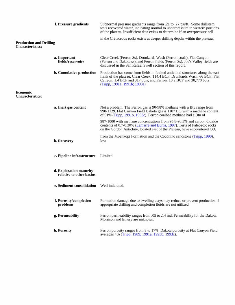
l. Pressure gradients Subnormal pressure gradients range from .21 to .27 psi/ft. Some drillstem tests recovered water, indicating normal to underpressure in western portions of the plateau. Insufficient data exists to determine if an overpressure cell
in the Cretaceous rocks exists at deeper drilling depths within the plateau.Production and Drilling Characteristics:
a. Important fields/reservoirs
Clear Creek (Ferron Ss), Drunkards Wash (Ferron coals), Flat Canyon (Ferron and Dakota ss), and Ferron fields (Ferron Ss). Joe's Valley fields are discussed in the San Rafael Swell section of this report.
b. Cumulative production Production has come from fields in faulted anticlinal structures along the east flank of the plateau. Clear Creek: 114.4 BCF; Drunkards Wash: 66 BCF; Flat Canyon: 1.4 BCF and 317 bbls; and Ferron: 10.2 BCF and 38,770 bbls (Tripp, 1991a, 1991b; 1993a).
Economic Characteristics:
a. Inert gas content Not a problem. The Ferron gas is 90-98% methane with a Btu range from 990-1129. Flat Canyon Field Dakota gas is 1107 Btu with a methane content of 91% (Tripp, 1991b, 1993c). Ferron coalbed methane had a Btu of
987-1000 with methane concentrations from 95.8-98.3% and carbon dioxide contents of 0.7-0.30% (Lamarre and Burns, 1997). Tests of Paleozoic rocks on the Gordon Anticline, located east of the Plateau, have encountered CO2
from the Moenkopi Formation and the Coconino sandstone (Tripp, 1990).b. Recovery low
c. Pipeline infrastructure Limited.
d. Exploration maturity relative to other basins
e. Sediment consolidation Well indurated.
f. Porosity/completion problems
Formation damage due to swelling clays may reduce or prevent production if appropriate drilling and completion fluids are not utilized.
g. Permeability Ferron permeability ranges from .05 to .14 md. Permeability for the Dakota, Morrison and Emery are unknown.
h. Porosity Ferron porosity ranges from 8 to 17%; Dakota porosity at Flat Canyon Field averages 4% (Tripp, 1989; 1991a; 1993b; 1993c).
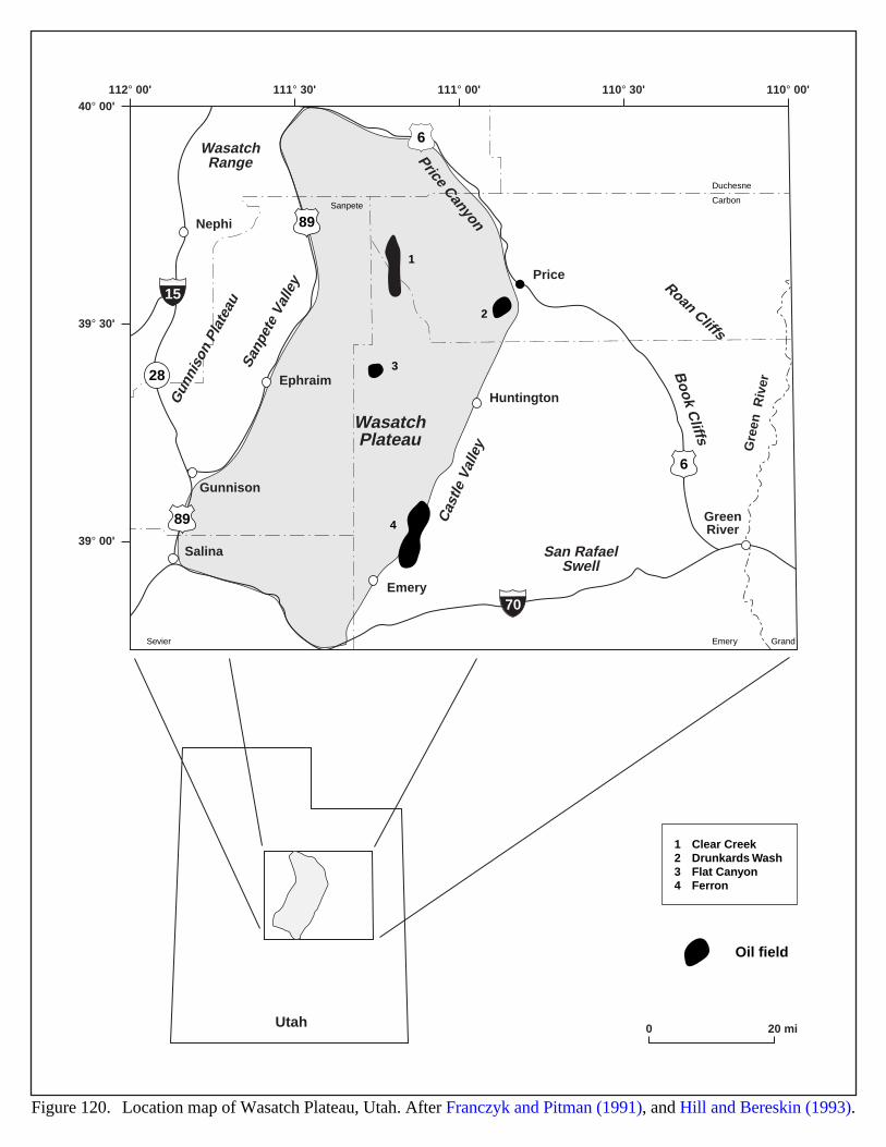
112° 00'40° 00'
39° 30'
39° 00'
111° 30' 111° 00' 110° 30' 110° 00'
6
6
Salina
Gunnison
Ephraim
Nephi
Emery
Huntington
Price
GreenRiver
Gre
enR
iver
WasatchPlateau
WasatchRange Price Canyon
Roan Cliffs
Book C
liffs
San RafaelSwell
Cas
tle V
alle
y
Sanp
ete
Valle
y
Gun
niso
n Pl
atea
u
89
89
70
15
EmerySevier
Carbon
Duchesne
Sanpete
Grand
28
2
1
3
4
0 20 miUtah
Figure 120. Location map of Wasatch Plateau, Utah. After Franczyk and Pitman (1991), and Hill and Bereskin (1993).
Oil field
1234
Clear CreekDrunkards WashFlat CanyonFerron
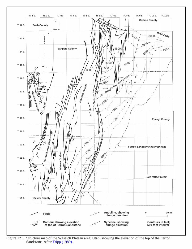
R. 1 E. R. 2 E. R. 3 E. R. 4 E. R. 5 E. R. 6 E. R. 7 E. R. 8 E. R. 9 E. R. 10 E. R. 11 E.
T. 12 S.
T. 13 S.
T. 14 S.
T. 15 S.
T. 16 S.
T. 17 S.
T. 18 S.
T. 19 S.
T. 20 S.
T. 21 S.
T. 22 S.
T. 23 S.
T. 24 S.
T. 25 S.
40004000
4000
4000
4000
5000
5000
5000
5500
4500
4500
4500
4500
3500
3500
3500
3500
3000
3000
3000
Juab County
Sanpete County
Sevier County
Carbon County
Emery County
Ferron Sandstone outcrop edge
Straight C
anyon syncline
San Rafael Swell
Book Cliffs
Mu
sin
a G
rab
en
Fish Creek Graben
Joe'
s V
alle
y G
rabe
n
Was
atch
mon
oclin
e
Para
dise
faul
t zon
e
Was
atch
Pla
teau
Gunnison P
lateau
Fault
3000 Contour showing elevation of top of Ferron Sandstone
0 10 miAnticline, showing plunge direction
Contours in feet;500 foot interval
Syncline, showing plunge direction
Figure 121. Structure map of the Wasatch Plateau area, Utah, showing the elevation of the top of the Ferron Sandstone. After Tripp (1989).
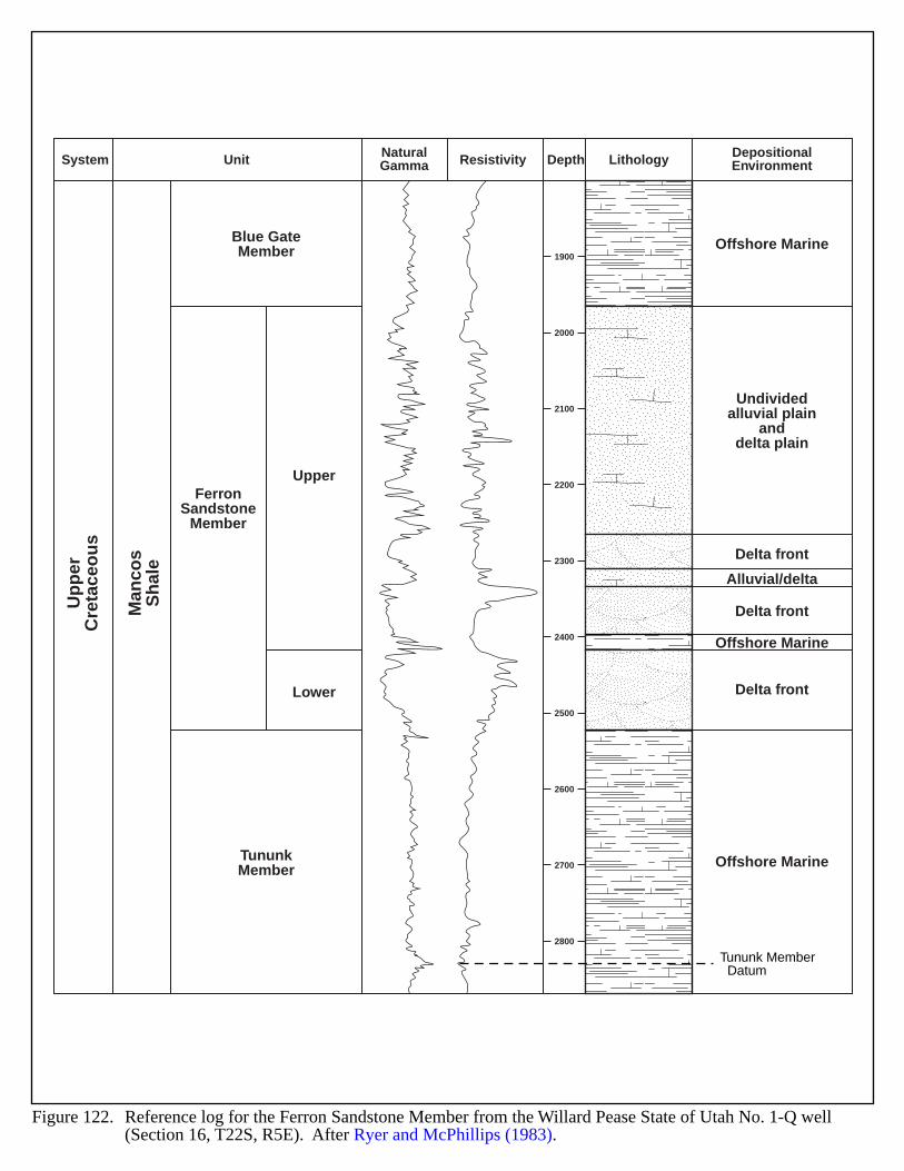
1900
2000
2100
2200
2300
2400
2500
2600
2700
2800
Up
per
Cre
tace
ou
s
Man
cos
Sh
ale
Blue GateMember Offshore Marine
Offshore Marine
Offshore Marine
Undividedalluvial plain
anddelta plain
Delta front
Delta front
Delta front
Alluvial/delta
TununkMember
FerronSandstone
Member
Upper
Lower
System Unit NaturalGamma Resistivity Depth Lithology Depositional
Environment
Tununk Member Datum
Figure 122. Reference log for the Ferron Sandstone Member from the Willard Pease State of Utah No. 1-Q well (Section 16, T22S, R5E). After Ryer and McPhillips (1983).
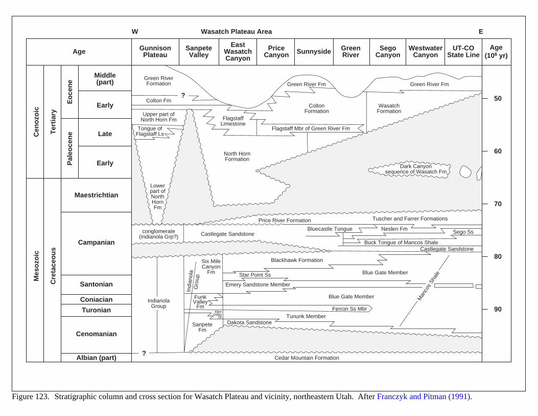
?
?
Middle(part)
Early
GunnisonPlateau
Wasatch Plateau AreaW E
SanpeteValley
PriceCanyon SunnysideAge Green
RiverSego
CanyonWestwater
CanyonUT-CO
State LineAge
(106 yr)
EastWasatchCanyon
Cen
ozo
ic
Ter
tiar
y
Eo
cen
eP
aleo
cen
e
Cre
tace
ou
s
Mes
ozo
ic
Late
Early
Maestrichtian
Campanian
Santonian
Coniacian
Turonian
Cenomanian
Albian (part)
Green RiverFormation
Upper part ofNorth Horn Fm
North HornFormation
conglomerate(Indianola Grp?)
IndianolaGroup
Lowerpart ofNorthHornFm
ColtonFormation
WasatchFormation
Dark Canyonsequence of Wasatch Fm
FlagstaffLimestone
Tongue ofFlagstaff Ls
Green River Fm
Flagstaff Mbr of Green River Fm
Colton Fm
Castlegate SandstoneBluecastle Tongue
Castlegate SandstoneBuck Tongue of Mancos Shale
Neslen Fm Sego Ss
Price River Formation
Blackhawk Formation
Cedar Mountain Formation
Blue Gate Member
Blue Gate Member
Star Point Ss
Emery Sandstone Member
Dakota Sandstone
Ferron Ss MbrTununk Member
Six MileCanyon
Fm
SanpeteFm
FunkValley
FmAllen
ValleySh
Tuscher and Farrer Formations
Green River Fm
Indi
anol
aG
roup
Man
cos
Shal
e
50
60
70
80
90
Figure 123. Stratigraphic column and cross section for Wasatch Plateau and vicinity, northeastern Utah. After Franczyk and Pitman (1991).
264
WESTERN WASHINGTON (WILLAMETTE-PUGET SOUND TROUGH)
GEOLOGIC SETTING
The Willamette-Puget Sound trough extends south from Vancouver Island in British Columbia 490 mi to theKlamath Mountains in southwestern Oregon (Figure 124) (Johnson et al., 1997; Johnson and Tennyson, 1996). Innorthern Washington, the Olympic Mountains interrupt this general trend . The Cascade Range forms the easternboundary. The trough extends 50 to 140 mi offshore to an approximate depth of 3,300 ft on the continental shelf(Armentrout and Suek, 1985). Within the trough are the Tyee, South Willamette, North Willamette, Nehelem, andSeattle basins. West of the main part of the trough and adjacent to the Pacific coastline are four subbasins: CoosBay, Newport, Astoria, and Willapa (Armentrout and Suek, 1985; Johnson et al., 1997; and Johnson and Tennyson,1996).
Around the northern, northeastern and southern margins, accreted terranes of Mesozoic sedimentary, volcanic andmetamorphic rocks crop out and may underlie the eastern part of the trough (Johnson et al., 1997; Johnson andTennyson, 1996). Up to 20,000 feet of Cenozoic forearc sediments overlie pre-Tertiary igneous and metamorphicbasement. Figure 125 shows the stratigraphy for various play areas in western Washington. Depositionalenvironments included fluvial, fan-delta, delta, shallow-marine, continental-slope and submarine fan (Johnson et al.,1997; Johnson and Tennyson, 1996).
Oligocene to Pliocene uplift occurred simultaneously with subsidence of local depositional areas. Late Miocenebasalt flows flooded the Columbia River and northern Willamette Valleys, and associated intrusive activity occurredconcurrently. The Columbia River deposited deltaic and shallow-marine sediments in southwestern Washington andnorthwestern Oregon (Astoria and Montesano Formations) from Miocene to Pliocene time (Figure 125). Subductionalong the continental margin during the Eocene caused extensive folding, faulting, uplift and subsidence (Johnson etal., 1997; Johnson and Tennyson, 1996).
Conventional sandstone reservoir candidates include the shallow marine Spencer and Cowlitz Formations, thedeltaic to submarine fan Tyee Formation, the fluvial Chuckanut Formation, and the deltaic Puget Group.
HYDROCARBON PRODUCTION
Many oil and gas seeps occur along the Washington coast, and hydrocarbon exploration began in 1881. Morethan 500 wells have been drilled in the Pacific Northwest, but most are less than 5,000 feet deep. The onlycommercially productive hydrocarbon reservoir in the Willamette-Puget Sound trough is Mist gas field, a faulted,structural trap located northwest of Portland, Oregon (Armentrout and Suek, 1985) (Figure 124). Since its discoveryin 1979, Mist field has produced over 70 BCFG from sandstones in the Eocene Cowlitz Formation.
Before discovery of the Mist gas field, the only hydrocarbon production in the region came from the Bellingham-Watcom County coal fields, the Rattlesnake Hills field near Yakima in the Columbia Plateau, and the Grays Harbor-Ocean City field, which to date has produced about 12,000 BO plus some associated gas (McFarland, 1981;Armentrout and Suek, 1985) (Figure 124).
265
EVIDENCE FOR BASIN-CENTERED GAS
In the northern Willamette basin, the lower Cowlitz Formation strata entered the oil-generating window about33 Ma (Armentrout and Suek, 1985). Upper Cowlitz rocks entered the generation window at 3 Ma. Present-daygeothermal gradients average 15 °F per 1,000 ft; thus, present-day reservoir temperatures should support gasgeneration at depths exceeding 7,000 ft. This depth is slightly shallower than the 8,000 ft depth of the overpressuredenvelope. Favorable parameters exist elsewhere in the trough that suggest in-situ gas generation is taking place.
Eocene coals and carbonaceous shales are potential gas-prone source rocks. Total organic carbon (TOC) contentin the Willamette basin varies from 0.65% to 7.22% for marine shales and siltstones of the Cowlitz Formation;interbedded coals have up to 55% TOC (Johnson and Tennyson, 1996; Johnson et al., 1997). Vitrinite reflectancevalues range from 0.24 to 4.01 across the basin. High values result from contact metamorphism near igneousintrusions along the Cascades. Projected temperatures within the hydrocarbon generation window range from 90 to140 °C (Armentrout and Suek, 1985).
The shales encasing the Mist field reservoir are thermally immature, with Ro values less than 0.4% (Armentroutand Suek, 1985). The gas within the reservoir probably generated deep in the basin and migrated updip into theshallow structural trap.
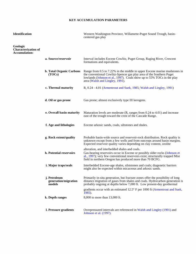
KEY ACCUMULATION PARAMETERS
Identification Western Washington Province, Willamette-Puget Sound Trough, basin-centered gas play
Geologic Characterization of Accumulation:
a. Source/reservoir Interval includes Eocene Cowlitz, Puget Group, Raging River, Crescent formations and equivalents.
b. Total Organic Carbons (TOCs)
Range from 0.5 to 7.22% in the middle to upper Eocene marine mudstones in the conventional Cowlitz-Spencer gas play area of the Southern Puget lowlands (Johnson et al., 1997). Coals show up to 55% TOCs in the play area (Walsh and Lingley, 1991).
c. Thermal maturity Ro 0.24 - 4.01 (Armentrout and Suek, 1985; Walsh and Lingley, 1991)
d. Oil or gas prone Gas prone; almost exclusively type III kerogens.
e. Overall basin maturity Maturation levels are moderate (Ro ranges from 0.24 to 4.01) and increase east of the trough toward the crest of the Cascade Range.
f. Age and lithologies Eocene arkosic sands, coals, siltstones and shales.
g. Rock extent/quality Probable basin-wide source and reservoir-rock distribution. Rock quality is unknown except from a few wells and from outcrops around basin margins. Expected reservoir quality varies depending on clay content, zeolite
alteration, and interbedded shales and coals.h. Potential reservoirs Gas-bearing reservoirs occur in Eocene or possibly older rocks (Johnson et
al., 1997); very few conventional reservoirs exist; structurally trapped Mist field in northern Oregon has produced more than 70 BCFG.
i. Major traps/seals Interbedded Eocene-age shales, silststones and coals; diagenetic barriers might also be expected within micaceous and arkosic sands.
j. Petroleum generation/migration models
Primarily in-situ generation, but fracture zones offer the possibility of long distance migration of gases from shales and coals. Hydrocarbon generation is probably ongoing at depths below 7,000 ft. Low present-day geothermal
gradients occur with an estimated 12.5° F per 1000 ft (Armentrout and Suek, 1985).
k. Depth ranges 8,000 to more than 13,000 ft.
l. Pressure gradients Overpressured intervals are referenced in Walsh and Lingley (1991) and Johnson et al. (1997).
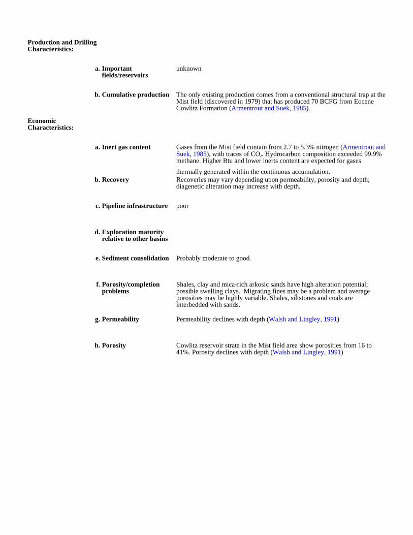
Production and Drilling Characteristics:
a. Important fields/reservoirs
unknown
b. Cumulative production The only existing production comes from a conventional structural trap at the Mist field (discovered in 1979) that has produced 70 BCFG from Eocene Cowlitz Formation (Armentrout and Suek, 1985).
Economic Characteristics:
a. Inert gas content Gases from the Mist field contain from 2.7 to 5.3% nitrogen (Armentrout and Suek, 1985), with traces of CO2. Hydrocarbon composition exceeded 99.9% methane. Higher Btu and lower inerts content are expected for gases
thermally generated within the continuous accumulation.b. Recovery Recoveries may vary depending upon permeability, porosity and depth;
diagenetic alteration may increase with depth.
c. Pipeline infrastructure poor
d. Exploration maturity relative to other basins
e. Sediment consolidation Probably moderate to good.
f. Porosity/completion problems
Shales, clay and mica-rich arkosic sands have high alteration potential; possible swelling clays. Migrating fines may be a problem and average porosities may be highly variable. Shales, siltstones and coals are interbedded with sands.
g. Permeability Permeability declines with depth (Walsh and Lingley, 1991)
h. Porosity Cowlitz reservoir strata in the Mist field area show porosities from 16 to 41%. Porosity declines with depth (Walsh and Lingley, 1991)
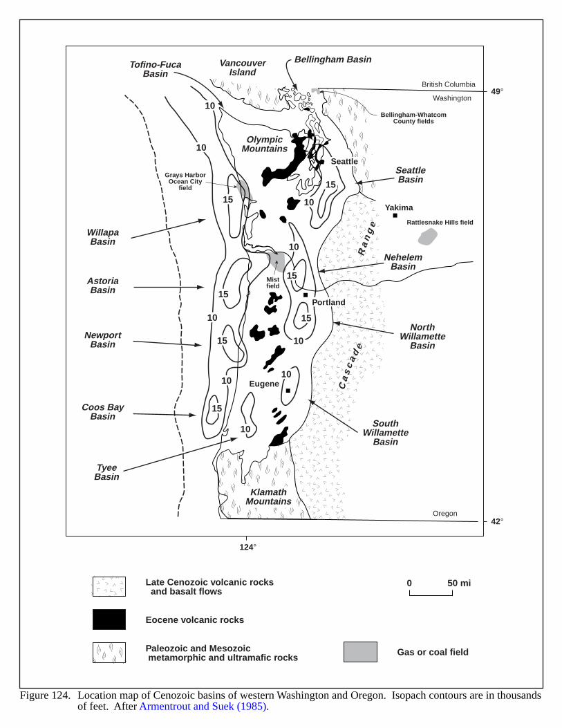
KlamathMountains
VancouverIsland
Ca
sc
ad
eR
an
ge
OlympicMountains
Bellingham-WhatcomCounty fields
Grays HarborOcean City
field
Rattlesnake Hills field
Mistfield
SeattleBasin
Bellingham BasinTofino-FucaBasin
NehelemBasin
NorthWillamette
Basin
SouthWillamette
Basin
TyeeBasin
WillapaBasin
AstoriaBasin
NewportBasin
Coos BayBasin
Eugene
Portland
Oregon
Washington
British Columbia
Seattle
Yakima
10
10
10
10
10
10
10
10
10
15
15
15
15
15
15
15
49°
42°
124°
0 50 mi
Figure 124. Location map of Cenozoic basins of western Washington and Oregon. Isopach contours are in thousandsof feet. After Armentrout and Suek (1985).
Late Cenozoic volcanic rocks and basalt flows
Eocene volcanic rocks
Paleozoic and Mesozoic metamorphic and ultramafic rocks Gas or coal field
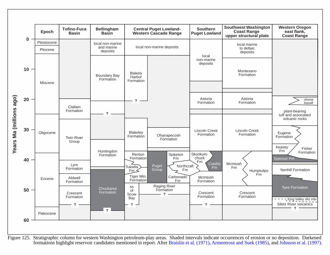
0
10
20
30
40
50
60
Year
s M
a (m
illio
ns
ago
)
EpochCentral Puget Lowland-Western Cascade Range
Southwest WashingtonCoast Range
upper structural plate
Western Oregoneast flank,
Coast Range
SouthernPuget Lowland
Pleistocene
Pliocene
Miocene
Oligocene
Eocene
Paleocene
local non-marine deposits
localnon-marine
deposits
local marineto deltaicdeposits
?
?
?
??
BlakeleyFormation
Boundary BayFormation
HuntingdonFormation
ClallamFormation
LyreFormation
AldwellFormation
CrescentFormation
Twin RiverGroup
AstoriaFormation
Lincoln CreekFormation
McIntoshFormation
McIntoshFm
HumptulipsFm
CrescentFormation
CrescentFormation
Lincoln CreekFormation
AstoriaFormation
MontesanoFormation
olivinebasalt
KeaseyFm
King Valley slts mbr
plant-bearingtuff and associated
volcanic rocks
Yamhill Formation
Tyee Formation
Siletz River volcanics
EugeneFormation
Spencer Fm
FisherFormation
ssof
ScowBay
OhanapecoshFormation
Raging RiverFormation
RentonFormation
PugetGroup
NorthcraftFm
SpiketonFm
Skookum-chuck
Fm CowlitzFm
CarbonadoFm
TukwilaFm
Tiger Mtn.Formation
BlakelyHarbor
Formation
BellinghamBasin
?
?
Tofino-FucaBasin
?
ChuckanutFormation
local non-marineand marine
deposits
Figure 125. Stratigraphic column for western Washington petroleum-play areas. Shaded intervals indicate occurrences of erosion or no deposition. Darkenedformations highlight reservoir candidates mentioned in report. After Braislin et al. (1971), Armentrout and Suek (1985), and Johnson et al. (1997).
270
REFERENCES
Al-Shaieb, Z., Puckette, J.O., Abdalla, A.A. and Ely, P.B., 1997a, Megacompartment complex in theAnadarko Basin–a completely sealed overpressured phenomenon, in Gas Research Institute Workshop,Compartmentalization of Overpressured Reservoirs in the Anadarko Basin–Implications forExploration and Development: Gas Research Institute, Oklahoma City, p. 1-14.
Al-Shaieb, Z., Puckette, J.O., Abdalla, A.A. and Ely, P.B., 1997b, Three levels of compartmentationwithin the overpressured interval of the Anadarko Basin, in Gas Research Institute Workshop:Compartmentalization of Overpressured Reservoirs in the Anadarko Basin–Implications forExploration and Development: Gas Research Institute, Oklahoma City, p. 15-29.
Al-Shaieb, Z., Puckette, J., Ely, P., and Tigert, V., 1990, Pressure Compartments and Seals in theAnadarko Basin, in Johnson, K.S., and Cardott, B.J., eds., Source Rocks in the Midcontinent, 1990Symposium: Oklahoma Geological Survey Circular 93, p. 210-228.
Al-Shaieb, Z., and Shelton, J.W., 1977, Evaluation of uranium potential in selected Pennsylvanian andPermian units and igneous rocks in southwestern and southern Oklahoma: U.S. Department ofEnergy, Open-File Report GJBX-35 (78), 248 pp.
Aldy, W., 1994, Well log determination of the organic richness of the Mowry Shale in the North Park andDenver Basins and the Niobrara Chalk in the Denver Basin: Colorado School of Mines, Master ofScience thesis, 86 pp.
Anderson, R.R., and Black, R.A., 1982, Geological interpretations from geophysical models of theMidcontinent geophysical anomaly in southwest Iowa, in Regional tectonics and seismicity ofsouthwestern Iowa: Annual Report of U.S. Nuclear Regulatory Commission NUREG/CR-2548, p.27-41.
Arbenz, J.K., 1956, Tectonic map of Oklahoma: Oklahoma Geological Survey Map GM-3.Armentrout, J.M., and Suek, D.H., 1985, Hydrocarbon Exploration in Western Oregon and Washington:
American Association of Petroleum Geologists Bulletin, v. 69, no. 4, p. 627-643.Armstrong, R.L., 1968, Sevier Orogenic Belt in Nevada and Utah: Geological Society of America Bulletin
79, no. 4, p. 429-458.Asreen, R.C., Jr., 1990, Kingdom (Abo Reef), in Vanderhill, A. L., C.B. Godfrey, and F. Heard eds., Oil
and Gas Fields in West Texas Symposium Volume V: Midland, Texas, West Texas GeologicalSociety, Pub. # 90-86, p. 117-120.
Baars, D.L., and Stevenson, G.M., 1981, Tectonic evolution of the Paradox Basin, Utah and Colorado, inGeology of the Paradox Basin: Rocky Mountain Association of Geologists, p. 23-31.
Bailey, E.H., ed., 1966, Geology of Northern California: California Division of Mines and Geology Bulletin190, 508 pp.
Banet, A. C., Jr., 1991, Oil and gas development on Alaska’s North Slope–past results and future prospects:U.S.D.I. Bureau of Land Management, Alaska, Open-File Report 34, 42 pp.
Barber, C., 1979. Generation, migration, trapping and alteration of petroleum–an introduction forexploration geologists: Rocky Mountain Association of Geologists, Continuing Education ShortCourse Notes, 50 pp.
Barker, C.E., 1996a, Resource assessment of the Bureau of Land Management’s Winnemucca District andSurprise Resource Area, Northwest Nevada and Northeast California–geochemical analysis andthermochronologic modeling to evaluate conceptual petroleum plays: U.S. Geological Survey Open-File Report 96-051.
Barker, C.E., 1996b, Salton Trough Province (016), in Gautier, D.L., Dolton, G.L., Takahashi, K.I., andVarnes, K.L., eds., 1995 National Assessment of United States Oil and Gas Resources–Results,Methodology, and Supporting Data: U.S. Geological Survey Digital Data Series 30, Release 2, CD-ROM.
Barker, C.E., Pollastro, R.M., and Wandrey, C.J., 1996, Park Basins Province (038), in Gautier, D.L.,Dolton, G.L., Takahashi, K.I., and Varnes, K.L., eds., 1995 National Assessment of United StatesOil and Gas Resources–Results, Methodology, and Supporting Data: U.S. Geological Survey DigitalData Series 30, Release 2, CD-ROM.
Barker, C.E. and Elders, W.A., 1981, Vitrinite reflectance geothermometry and apparent heating duration inthe Cerro Prieto Geothermal Field: Geothermics, v. 10, p. 207-223.
271
Barnes, D.A., Girard, J.P., and Aronson, J.L., 1992, K-Ar dating of illite diagenesis in the MiddleOrdovician St. Peter Sandstone, Central Michigan Basin, USA–implications for thermal history, inHouseknecht, D.W., and Pittman, E.D., eds., Origin, diagenesis, and petrophysics of clay minerals insandstones: Society of Economic Paleontologists and Mineralogists Special Publication 47. p. 35-48.
Bartberger, C.E., and Dyman, T.S., in press, Is there a basin-center gas accumulation in the Colville basin,Alaska?: in Nuccio, V.F., and Dyman, T.S., eds., Geologic Studies of Basin-Center Gas Systems:U.S. Geological Survey Bulletin 2184 series.
Bartberger, C.E., Dyman, T.S., and Condon, S.M., in press, Is there a basin-center gas accumulation in theCotton Valley Sandstone, Gulf Coast basin, USA? in Nuccio, V.F., and Dyman, T.S., eds., GeologicStudies of Basin-Center Gas Systems: U.S. Geological Survey Bulletin 2184 series.
Bearden, B.L., and Mancini, E.A., 1985, Petroleum geology of Carter Sandstone (Upper Mississippian),Black Warrior Basin, Alabama: American Association of Petroleum Geologists Bulletin, v. 69, no. 3,p. 361-377.
Bebout, D.G., and Garret, C.M., Jr., 1989, PM-2. Spraberry and Dean Sandstone, Midland Basin–Atlas ofMajor Texas Gas Reservoirs: Gas Research Institute and Bureau of Economic Geology, Austin,Texas, p.121-122.
Bermejo, F.J., Navarro, F.X., Esquer, C.A., Castillo, F., and de la Cruz, F.C., 1981, Pressure changes andtheir effects on the Cerro Prieto Geothermal Field, in Proceedings, Third Symposium on the CerroPrieto Geothermal Field, Baja California, Mexico: Lawrence Berkeley Laboratory, Berkeley,California, Report LBL-11967, p. 464-482.
Beyer, L.A., 1996, Pacific Coast Province, in Gautier, D.L., Dolton, G.L., Takahashi, K.I., and Varnes,K.L., eds., 1995 National Assessment of United States Oil and Gas Resources–Results,Methodology, and Supporting Data: U.S. Geological Survey Digital Data Series DDS-30, 144 pp.,28 figs.
Beyer, L.A., 1988, Summary of geology and petroleum plays used to assess undiscovered recoverablepetroleum resources of Los Angeles Basin province, California: U.S. Geological Survey Open-FileReport 88-450L.
Bierei, M.A., 1987, Hydrocarbon maturation, source rock potential, and thermal evolution of LateCretaceous and Early Tertiary rocks of Hanna basin, southeastern Wyoming: University of Wyoming,Laramie, Master of Science thesis, 151 pp.
Bierei, M.A., and Surdham, R.C., 1986, Hydrocarbon maturation, source rock potential, and thermalevolution of Late Cretaceous and Early Tertiary rocks of Hanna basin, southeastern Wyoming:American Association of Petroleum Geologists Bulletin, v. 70, no. 8, p. 1031.
Biggs, P., 1957, CO2 at North and South McCallum, in Finch, W.C., ed., Guidebook to the geology ofNorth and Middle Parks Basin, Colorado: Rocky Mountain Association of Geologists, 9th AnnualField Conference, p. 115-118.
Bird, K.J., 1996, Region 1, Alaska–Geologic Framework, in Gauthier, D.L., Dolton, G.L., Takahashi, K.I.,and Varnes, K.L., eds., 1995 National Assessment of United States Oil and Gas Resources–Results,Methodology, and Supporting Data, U.S. Geol. Survey Digital Data Series DDS-30, Rel. 2, p. 1-2.
Bird, K.J., 1994, Ellesmerian(!) petroleum system, North Slope of Alaska, U.S.A., in Magoon, L.B., andW.G. Dow, eds., The petroleum system–from source to trap: American Association of PetroleumGeologists Memoir 60, p. 339-358.
Bird, K.J., 1991, Geology, play descriptions, and petroleum resources of the Alaskan North Slope(Petroleum Provinces 58-60), U. S. Geological Survey Open-File Report 88-450Y, 52 pp.
Bishop, C.E. and Tripp, B.T., 1993, An overview of the tar sand resources of Utah: American Associationof Petroleum Geologists Bulletin v. 77, p. 1445 (Abstract).
Black, B., 1998, Exploring the Rio Grande Rift–frontier and underexplored basins of New Mexico:Petroleum Technology Transfer Council, Southwest Regional Lead Organization, 1 pp.
Black, B., 1982, Oil and gas exploration in the Albuquerque Basin–Albuquerque Country II: New MexicoGeological Society Guidebook, 33rd Field Conference, p. 313-323.
Bodily, D.M., Hucka, V.J. and Huang, H., 1991, Correlation of chemical structure of coals in the BookCliffs and Wasatch Plateau Fields with methane formation and retention, east-central Utah, inChidsey, T.C., Jr., ed., Geology of east-central Utah: Utah Geological Association Publication 19, p.211-222.
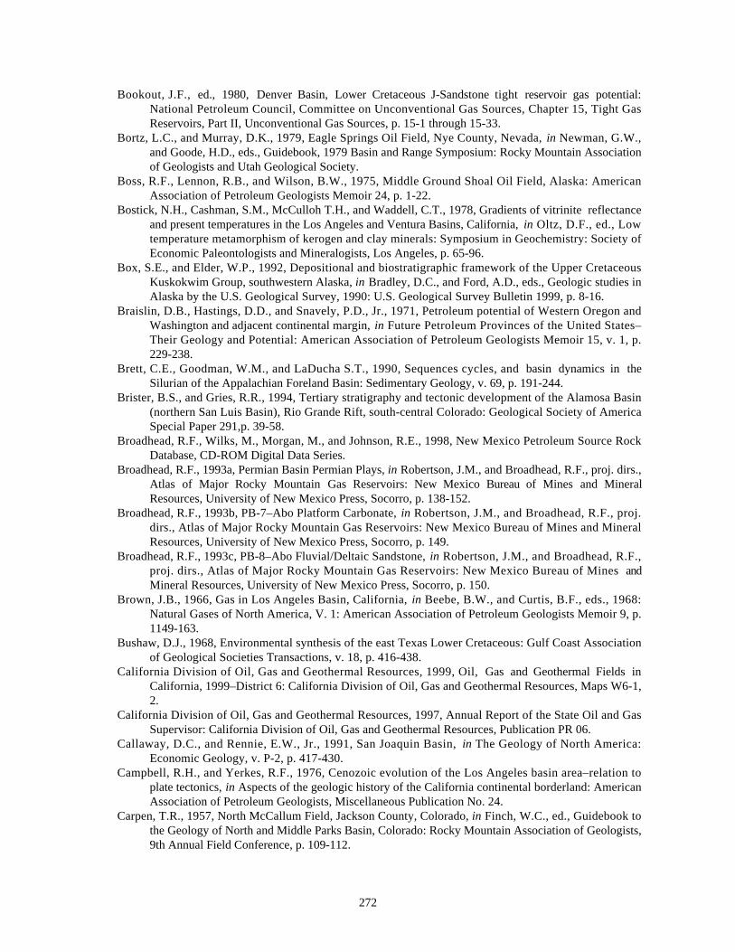
272
Bookout, J.F., ed., 1980, Denver Basin, Lower Cretaceous J-Sandstone tight reservoir gas potential:National Petroleum Council, Committee on Unconventional Gas Sources, Chapter 15, Tight GasReservoirs, Part II, Unconventional Gas Sources, p. 15-1 through 15-33.
Bortz, L.C., and Murray, D.K., 1979, Eagle Springs Oil Field, Nye County, Nevada, in Newman, G.W.,and Goode, H.D., eds., Guidebook, 1979 Basin and Range Symposium: Rocky Mountain Associationof Geologists and Utah Geological Society.
Boss, R.F., Lennon, R.B., and Wilson, B.W., 1975, Middle Ground Shoal Oil Field, Alaska: AmericanAssociation of Petroleum Geologists Memoir 24, p. 1-22.
Bostick, N.H., Cashman, S.M., McCulloh T.H., and Waddell, C.T., 1978, Gradients of vitrinite reflectanceand present temperatures in the Los Angeles and Ventura Basins, California, in Oltz, D.F., ed., Lowtemperature metamorphism of kerogen and clay minerals: Symposium in Geochemistry: Society ofEconomic Paleontologists and Mineralogists, Los Angeles, p. 65-96.
Box, S.E., and Elder, W.P., 1992, Depositional and biostratigraphic framework of the Upper CretaceousKuskokwim Group, southwestern Alaska, in Bradley, D.C., and Ford, A.D., eds., Geologic studies inAlaska by the U.S. Geological Survey, 1990: U.S. Geological Survey Bulletin 1999, p. 8-16.
Braislin, D.B., Hastings, D.D., and Snavely, P.D., Jr., 1971, Petroleum potential of Western Oregon andWashington and adjacent continental margin, in Future Petroleum Provinces of the United States–Their Geology and Potential: American Association of Petroleum Geologists Memoir 15, v. 1, p.229-238.
Brett, C.E., Goodman, W.M., and LaDucha S.T., 1990, Sequences cycles, and basin dynamics in theSilurian of the Appalachian Foreland Basin: Sedimentary Geology, v. 69, p. 191-244.
Brister, B.S., and Gries, R.R., 1994, Tertiary stratigraphy and tectonic development of the Alamosa Basin(northern San Luis Basin), Rio Grande Rift, south-central Colorado: Geological Society of AmericaSpecial Paper 291,p. 39-58.
Broadhead, R.F., Wilks, M., Morgan, M., and Johnson, R.E., 1998, New Mexico Petroleum Source RockDatabase, CD-ROM Digital Data Series.
Broadhead, R.F., 1993a, Permian Basin Permian Plays, in Robertson, J.M., and Broadhead, R.F., proj. dirs.,Atlas of Major Rocky Mountain Gas Reservoirs: New Mexico Bureau of Mines and MineralResources, University of New Mexico Press, Socorro, p. 138-152.
Broadhead, R.F., 1993b, PB-7–Abo Platform Carbonate, in Robertson, J.M., and Broadhead, R.F., proj.dirs., Atlas of Major Rocky Mountain Gas Reservoirs: New Mexico Bureau of Mines and MineralResources, University of New Mexico Press, Socorro, p. 149.
Broadhead, R.F., 1993c, PB-8–Abo Fluvial/Deltaic Sandstone, in Robertson, J.M., and Broadhead, R.F.,proj. dirs., Atlas of Major Rocky Mountain Gas Reservoirs: New Mexico Bureau of Mines andMineral Resources, University of New Mexico Press, Socorro, p. 150.
Brown, J.B., 1966, Gas in Los Angeles Basin, California, in Beebe, B.W., and Curtis, B.F., eds., 1968:Natural Gases of North America, V. 1: American Association of Petroleum Geologists Memoir 9, p.1149-163.
Bushaw, D.J., 1968, Environmental synthesis of the east Texas Lower Cretaceous: Gulf Coast Associationof Geological Societies Transactions, v. 18, p. 416-438.
California Division of Oil, Gas and Geothermal Resources, 1999, Oil, Gas and Geothermal Fields inCalifornia, 1999–District 6: California Division of Oil, Gas and Geothermal Resources, Maps W6-1,2.
California Division of Oil, Gas and Geothermal Resources, 1997, Annual Report of the State Oil and GasSupervisor: California Division of Oil, Gas and Geothermal Resources, Publication PR 06.
Callaway, D.C., and Rennie, E.W., Jr., 1991, San Joaquin Basin, in The Geology of North America:Economic Geology, v. P-2, p. 417-430.
Campbell, R.H., and Yerkes, R.F., 1976, Cenozoic evolution of the Los Angeles basin area–relation toplate tectonics, in Aspects of the geologic history of the California continental borderland: AmericanAssociation of Petroleum Geologists, Miscellaneous Publication No. 24.
Carpen, T.R., 1957, North McCallum Field, Jackson County, Colorado, in Finch, W.C., ed., Guidebook tothe Geology of North and Middle Parks Basin, Colorado: Rocky Mountain Association of Geologists,9th Annual Field Conference, p. 109-112.
273
Catacosinos, P.A., and Daniels, P.A., Jr., 1991, Stratigraphy of Middle Proterozoic to Middle Ordovicianformations in the Michigan Basin, in Catacosinos, P.A. and Daniels, P.A., Jr., eds., EarlySedimentary Evolution of the Michigan Basin: Geological Society of America Special Paper 256. p.53-71.
Catacosinos, P.A., 1973, Cambrian lithostratigraphy of Michigan Basin: American Association ofPetroleum Geologists Bulletin, v. 57, p. 2404-2418.
Cercone, K.R., and Pollack, H.N., 1991, Thermal maturity of the Michigan Basin, in Catacosinos, P.A.,and Daniels, P.A., Jr., eds., Early sedimentary evolution of the Michigan Basin: Geological Societyof America Special Paper 256. p. 1-11.
Chapin, C.E. and Cather, S.M., 1994, Tectonic setting of the axial basins of the northern and central RioGrande Rift: Geological Society of America Special Paper 291, p. 5-25.
Charpentier, R.R., deWitt, W., Jr., Claypool, G.E., Harris, L.D., Mast, R.F., Megeath, J.D., Roen, J.B.,and Schmoker, J.W., 1993, Estimates of unconventional natural gas resources in the Devonian shalesof the Appalachian basin, in Roen, J.B., and Kepferle, R.C., eds., Petroleum geology of theDevonian and Mississippian black shale of eastern North America: U.S. Geological Survey Bulletin1909, p. N1-N20.
Cherven, V.B., 1983, A delta slope submarine fan model for Maestrichtian part of the Great ValleySequence: American Association of Petroleum Geologists Bulletin v. 62, no. 5, p. 772-816.
Chidsey, T.C., Jr., ed., 1991, Geology of east-central Utah: Utah Geological Association Publication 19,394 pp.
Clayton, J.L., Mudge, M.R., Lubeck, C.M., and Daws, T.A., 1982, Hydrocarbon source-rock evaluation ofthe Disturbed Belt, northwestern Montana, in Powers, R.B., ed., Geologic Studies of the CordilleranThrust Belt, Vol. 2: Rocky Mountain Association of Geologists, p. 777-804.
Clayton, J.L., and Swetland, P.J., 1977, Preliminary Report–Petroleum Geochemistry of the Denver Basin,in Veal, H.K., ed., Exploration Frontiers of the Central and Southern Rockies: Rocky MountainAssociation of Geologists, p. 223-233.
Cluff, R.M., 1999, Personal Communication: The Discovery Group, Inc.Coleman, J.L., Jr., and Coleman, C.J., 1981, Stratigraphic, sedimentologic, and diagenetic framework for
the Jurassic Cotton Valley Terryville massive sandstone complex, northern Louisiana: Gulf CoastAssociation of Geological Societies Transactions, v. 31, p. 71-79.
Colorado Oil and Gas Conservation Commission, 1997, Oil and gas statistics for the State of Colorado:Colorado Oil and Gas Conservation Commission.
Comer, J.B., and Hinch, H.H., 1987, Recognizing and quantifying expulsion of oil from the WoodfordFormation and age-equivalent rocks in Oklahoma and Arkansas: American Association of PetroleumGeologists Bulletin, v. 71, no. 7, p. 844-858.
Corbett, K.P., Friedman, M., and Spang, J., 1987, Fracture development and mechanical stratigraphy ofAustin Chalk, Texas: American Assoc. of Petroleum Geologists Bulletin, v. 71, no. 1, p. 17-28.
Crawford, F.D., 1970, Petroleum potential of Santa Maria Province, California, in Cram I.H., ed., FuturePetroleum Provinces of the United States, Vol. 1: American Association of Petroleum GeologistsMemoir 15, p. 316-329.
Daniels, P.A., 1982, Upper Precambrian sedimentary rocks, Oronto Group, Michigan-Wisconsin, inGeology and Tectonics of the Lake Superior Basin: Geological Society of American Memoir 156, p.5-14.
Dawson, W.C., 1997, Limestone microfacies and sequence stratigraphy, Eagle Ford Group, north-centralTexas outcrops: American Association of Petroleum Geologists Bulletin, v. 81, no. 9, p. 1573(abstract).
Dawson, W.C., Katz, B.J., Liro, L.M., and Robison, V.D., 1993, Stratigraphic and geochemical variability,Eagle Ford Group, east-central Texas: Proceedings, 14th Annual Society of Economic Paleontologistsand Mineralogists Gulf Coast Research Conference.
Devery, D.M., 1983, An overview of oil and gas potential in Mississippi: Oil and Gas Journal, v. 81, no.15, p. 129-134.
DeVoto, R.H., 1995, Geologic history of South Park, Colorado: Colorado School of Mines Quarterly, v.95, no. 1, p. 25-42.
274
Dibblee, T.W., 1984, Stratigraphy and tectonics of the San Felipe Hills, Borrego Badlands, SuperstitionHills, and Vicinity, in Rigsby, C.A., ed., The Imperial Basin–Tectonics, Sedimentation and ThermalAspects: Society of Economic Paleontologists and Mineralogists, Pacific section , v. 40, p. 31-44.
DiBona, P.A., and Kirschner, C.E., 1984, Geological bibliography for selected onshore sedimentary basinsof central and southern Alaska, stressing basin analysis and including an index of available well andsubsurface data: U.S. Geological Survey Open-File Report OF 84-99, 70 pp.
Dickas, A.B., 1986, Comparative Precambrian stratigraphy and structure along the Mid-Continent Rift:American Association of Petroleum Geologists Bulletin, v. 70, p. 225-238.
Dickinson, W.R., 1971, Clastic sedimentary sequences deposited in shelf, slope, and trough settings betweenmagmatic arcs and associated trenches: Pacific Geology, v. 3, p. 15-30.
Dolly, E.D. and Meissner, F.F., 1977, Geology and gas exploration potential, Upper Cretaceous and LowerTertiary strata, northern Raton Basin, in Veal, H.K., ed., Exploration Frontiers of the Central andSouthern Rockies: Rocky Mountain Association of Geologists, p. 247-270.
Dolson, J.C., and Muller, D.S., 1994, Stratigraphic evolution of the Lower Cretaceous Dakota Group,Western Interior, U.S.A., in Mesozoic Systems of the Rocky Mountain Region, U.S.A.: Society ofEconomic Paleontologists and Mineralogists, Rocky Mountain Section, Denver, p. 441-458.
Dolson, J.C., Piombino, J., Franklin, M., and Harwood, R., 1993, Devonian oil in Mississippian andMesozoic reservoirs–unconformity controls on migration and accumulation, Sweetgrass Arch,Montana: The Mountain Geologist, v. 30, p. 125-146.
Dott, R.H., Jr., and Nadon, G.C., 1992, Modeling of pressure compartments in the St. Peter Sandstone gasreservoir in the Michigan Basin, Final Report: Gas Research Institute 93/0015, 59 pp.
Dow, W.G., 1977, Kerogen studies and geological interpretations: Journal of Geochemical Exploration, v.7, p. 79-99.
Drzewiecki, P.A., Simo, A., Brown, P., Castrogiovanni, E., Nadon, G.C., Shepard, L.D., Valley, J.W.,Vandrey, M.R., and Winter, B.L., 1994, Diagenesis, diagenetic banding, and porosity evolution of theMiddle Ordovician St. Peter Sandstone and Glenwood Formation of the Michigan Basin, in Ortoleva,P., ed., Basin Compartments and Seals: American Association of Petroleum Geologists Memoir 61,p. 179-200.
Dryden, R.C., Erickson, R.C., Off, T., and Yost, S.W., 1965, Gas in Los Angeles Basin, California, inBeebe, B.W., and Curtis, B.F., eds., 1968, Natural Gases of North America, Vol. 1: AmericanAssociation of Petroleum Geologists Memoir 9, p. 135-149.
Duchscherer, W., Jr., 1972, Look deeper in the Black Warrior: Oil and Gas Jour. v. 70, no. 31, p. 146-151.Duffield, C., 1976, Geothermal technology systems and water cycles in arid lands: University of Arizona
Arid Lands Resource Information Paper no. 8, ch. V, p. 80-90.Dull, D., and Garber, R., eds., 1996, Oil and Gas Fields in West Texas, Symposium, Vol. VII: West Texas
Geological Society, Midland, Texas.Dunham, J.B., Bromley, B.W., and Rosato, V.J., 1986, Geologic controls on hydrocarbon occurrence within
the Santa Maria Basin of western California, in Gluskoter, H.J., Rice, D.D., and Taylor, R.B., eds.,Economic Geology, U.S.: Geological Society of America, v. P-2, p. 431-446.
Dutton, S.P., Clift, S.J., Hamilton, D.S., Hamlin, H.S., Hentz, T.F., Howard, W.E., Akhter, M.S., andLaubach, S.E., 1993a, Atlas of Major Low-Permeability Gas Reservoirs in the Continental UnitedStates: Gas Research Institute Topical Report, GRI-93/0044, 470 pp.
Dutton, S.P., Clift, S.J., Hamilton, D.S., Hamlin, H.S., Hentz, T.F., Howard, W.E., Akhter, M.S., andLaubach, S.E., 1993b, Major low-permeability sandstone gas reservoirs in the continental UnitedStates–Report of Investigations No. 211: University of Texas at Austin, Bureau of EconomicGeology, contract report prepared for Gas Research Institute, 221 pp.
Dutton, S.P., 1980, Petroleum source rock potential and thermal maturity, Palo Duro Basin, Texas: TexasBureau of Economic Geology Geological Circular 80-10, 48 pp.
Eaton, J.G., Kirkland, J.J., and Kauffman, E.G., 1990, Evidence and dating of Mid-Cretaceous tectonicactivity in the San Rafael Swell, Emery County, Utah: Mountain Geology, v. 27, p. 39-45.
Elder, W.P. and Kirkland, J.I., 1964, Cretaceous paleogeography of the southern Western Interior Region inMesozoic Systems of the Rocky Mountain Region, U.S.A.: Society of Economic Paleontologistsand Mineralogists, Rocky Mountain Section, Denver, p. 415-440.
275
Elders, W.A., 1979, The geological background of the geothermal fields of the Salton Trough, in Elders,W.A., ed., Geology and Geothermics of the Salton Trough: Geological Society of America Field TripGuidebook, UCR/IGPP-79/23, p. 1-19.
Ericksen, R.L., 1993, ARCO-Davis wildcat seeks answers to Black Warrior's deep mysteries: Oil and GasJournal, v. 91, no. 35, p. 101-103.
Erskine, M.C. Jr., Wolleben, J.A., and Lawler, D.L., 1984, A potential field interpretation of the structuraledge of the Cretaceous Hornbrook Basin in northern California, in Nilsen, T.H., ed. Geology of theUpper Cretaceous Hornbrook Formation, Oregon and California: Society of EconomicPaleontologists and Mineralogists, Pacific Section, v. 42, p. 211-219.
Evans, J.L., 1979, Major structural and stratigraphic features of the Anadarko basin, in Hyne, N.J., ed.,Pennsylvanian Sandstones of the Mid-Continent: Tulsa Geol. Survey Special Publ. no. 1, p. 97-113.
Ewing, T.E., 1983, Austin/Buda Fractured Chalk, in Galloway, W.E., Ewing, T.E., Garrett, C.M., andTyler, N., Atlas of Major Texas Oil Reservoirs: Univ. of Texas Bureau of Econ. Geology, p. 41-42.
Finley, R.J., 1986, An overview of selected blanket-geometry, low permeability gas sandstones in Texas, inSpencer, C.W., and Mast, R.F., eds., Geology of Tight Gas Reservoirs, AAPG Studies in Geology24: American Association of Petroleum Geologists, p. 69-85.
Foley, W.L., 1972, Sweetgrass arch; Figure 2: Oil and gas fields of the Sweetgrass arch, in Mallory,W.W., ed., Geologic Atlas of the Rocky Mountain Region: Rocky Mountain Association ofGeologists, Denver, Colorado, p. 264.
Ford, T.D., 1990, Grand Canyon Supergroup–Nankoweap Formation, Chuar Group, and SixtymileFormation, in Beus, S. and Morales, M., eds., Grand Canyon Geology, p. 49-70.
Forgotson, J.M., and Forgotson, J.M., Jr., 1976, Definition of Gilmer limestone, Upper Jurassic formation,northeastern Texas: American Association of Geologists Bulletin, v. 60, no. 7, p. 1119-1123.
Fouch, T.D., Wandrey, C.J., Pittman, J.W., Nuccio, V.F., Schmoker, J.W., Rice, D.D., Johnson, R.C.,and Dolton, G.L., 1992, Natural gas accumulations in low permeability Cretaceous and Tertiaryrocks, Uinta Basin, Utah: U.S. Department of Energy Report DOE/MC/20422-3051.
Fowler, J.H., and Kuenzi, W.D., 1978, Keweenawan turbidites in Michigan (deep borehole red beds)–afoundered basin sequence developed during evolution of a protoceanic rift system: Journal ofGeophysical Research, v. 83, p. 5833-5843.
Franczyk, K.J. and Pitman, J.K., 1991, Latest Cretaceous nonmarine depositional systems in the WasatchPlateau area–reflection of foreland to intermontane basin transition, in Chidsey, T.C., Jr., ed.,Geology of east-central Utah, Utah Geological Association Publication 19, p.77-93.
Frank, J.R., Jr., 1996, Kingdom (Abo Reef) Field, in Dull, D., and Garber, R., eds., Oil and Gas Fields inWest Texas, Symposium, Volume VII: West Texas Geological Society, Midland, Texas, p. 79-84.
Frenzel, H.N., Bloomer, R.R., Cline, R.B., Cys, J.M., Galley, J.E., Gibson, W.R., Hills, J.M., King,W.E., Seager, W.R., Kottlowski, F.E., Thompson, S., III, Luff, G.C., Pearson, B.T., and VanSiclen, D.C., 1988, The Permian Basin region, in Sloss, L.L., ed., The Geology of North America,Vol. D-2: Sedimentary Cover of the North American Craton: United States: Geological Society ofAmerica, p. 261-306.
Frez, J., and Gonzalez, J.J., 1991, Crustal structure and seismotectonics of northern Baja California, inDauphin, J.P., and Simoneit, B.R. eds., Amer. Assoc. of Petroleum Geol. Memoir 47, p. 261-283.
Fuis, G.S., and Zucca, J.J., 1984, A geologic cross section of northeastern California from seismicrefraction results, in Nilsen, T.H., ed. Geology of the Upper Cretaceous Hornbrook Formation,Oregon and California: Society of Economic Paleontologists and Mineralogists, Pacific Section, v.42, p. 203-209.
Fuis, G.S., Mooney, W.D., Healey, J.H., McMechan, G.A., and Lutter, W.J., 1982, Crustal structure ofthe Imperial Valley region, in The Imperial Valley, California, Earthquake of October 15, 1979: U.S.Geological Survey Professional Paper 1254, p. 25-49.
Gardett, P.H., 1971, Petroleum potential of Los Angeles Basin, California, in Cram I. H., ed., FuturePetroleum Provinces of the United States, V. 1: American Association of Petroleum GeologistsMemoir 15, p. 298-308.
Gas Research Institute, 1991, Executive summary of SFE No. 3–Application of advanced technologies intight gas sandstones-Travis Peak and Cotton Valley Formations: In Focus-Tight Gas Sands, v. 7, no.1, 73 pp.
276
Gautier, D.L., Dolton, G.L., Takahashi, K.I., and Varnes, K.L., eds., 1996, 1995 National Assessment ofUnited States Oil and Gas Resources–Results, Methodology, and Supporting Data: U.S. GeologicalSurvey Digital Data Series 30, version 2 [CD-ROM].
Gautier, D.L, Clayton, J.L., Leventhal, J.S. and Reddin, N.J., 1984, Origin and source-rock potential of thePierre Shale, Colorado and Kansas, in Woodward, J., Meissner, F.F. and Clayton, J.L., eds.,Hydrocarbon source rocks of the greater Rocky Mountain region: Rocky Mountain Association ofGeologists, p. 369-385.
Gibson, L.M., Malinconico, L.L., Downs, T., and Johnson, N.M., 1984, Structural implications of gravitydata from the Vallencito-Fish Creek Basin, western Imperial Valley, California, in Rigsby, C.A., ed.,The Imperial Basin–Tectonics, Sedimentation and Thermal Aspects: Society of EconomicPaleontologists and Mineralogists, Pacific Section v. 40, p. 15-29.
Giuseppe, A.C., and Heller, P.L., 1996, Long-term river response to regional doming in the Price RiverFormation, Central Utah: Geology, v. 26, no. 3, p. 239-242.
Grabowski, G.J. Jr., 1984, Generation and migration of hydrocarbons in Upper Cretaceous Austin Chalk,south-central Texas, in Source Rock Potential of Carbonate Rocks–AAPG Studies in Geology 18:American Association of Petroleum Geologists, p. 97-115.
Grabowski, G.J. Jr., 1981, Source rock potential of the Austin Chalk, Upper Cretaceous, southeasternTexas: Gulf Coast Association of Geological Societies Transactions, v. 31, p. 105-113.
Grether, W.J., and Morgan, K.A., 1988, Exploration and hydrocarbon potential of interior basins, Alaska(abstract): American Association of Petroleum Geologists Bulletin, v. 72, no. 2, p. 191-192.
Gromer, J.M., 1982, A geologic study of the Raton Basin: Gas Research Institute Topical Report #GRI-5011-321-0130, 47 pp.
Gromer, J.M., 1981, A geologic study of the Arkoma Basin and Ouachita Mountains: GRI Contract No. 01-321-0130, CER Corporation, 66 pp.
Hall, C.A., 1981, San Luis Obispo transform fault and Miocene rotation of the western Transverse Ranges,California: Journal Geophysical Research, v. 86, no. B2, p. 1015-1031.
Hammer, A.A., 1934, Rattlesnake Hills gas field, Benton County, Washington: American Association ofPetroleum Geologists Bulletin, v. 18, p. 847-859.
Hanson, B.M., Powers, B.K., Garret, C.M., Jr., McGookey, D.E., McGlasson, E.H., Horak, R.L.,Mazzullo, S.J., Reid, A.M., Calhoun, G.G., Clendening, J., and Claxton, B., 1991, The PermianBasin, in Gluskoter, H.J., Rice, D.D., and Taylor, R.B., eds., Economic Geology, United States, TheGeology of North America, Vol. P-2: Geological Society of America, p. 339-356.
Harris, D.C., and Baranoski, M.T., 1996, Precambrian pre-Knox Group play, in Roen J.B., and Walker B.J.,The Atlas of Major Appalachian Gas Plays: West Virginia Geological and Economical SurveyPublication V-25, p. 188-192.
Hastings, D.D., 1979, Results of exploratory drilling, northern Fallon Basin, western Nevada, in Newman,G.W., and Goode, H.D., eds., Guidebook, 1979 Basin and Range Symposium: Rocky MountainAssociation of Geologists and Utah Geological Society.
Hatch, J.R., and Morey, G.B., 1985, Hydrocarbon source rock evaluation of Middle Proterozoic SolorChurch Formation, North American Mid-Continent rift system, Rice County, Minnesota: AmericanAssociation of Petroleum Geologists Bulletin, v. 69, p. 1208-1216.
Hatch, J.R., and Morey, G.B., 1984, Hydrocarbon source rock evaluation, Solor Church Formation (MiddleProterozoic, Keweenawan Supergroup) southeastern Minnesota: U.S. Geological Survey Open-FileReport 84-554, 17 pp.
Helgeson, H.G., 1968, Geologic and thermodynamic characteristics of the Salton Sea geothermal system:American Journal of Science, v. 266, p. 129-166.
Hemborg, H. T., 1993, Denver Basin Plays-Overview, in Robertson, J.M., and Broadhead, R. F., Proj.Directors, Gorody, A.W., Contract Mgr., GRI, and Hjellming, C.A., Proj. Ed., Atlas of MajorRocky Mountain Gas Reservoirs: New Mexico Bureau of Mines and Mineral Resources, Socorro,NM, 206 pp. and 10 maps.
Henderson K.S., 1991, Cambro-Ordovician subsurface stratigraphy of the Black Warrior Basin inMississippi: Report of Investigations 2, Mississippi Department of Environmental Quality, Office ofGeology, Jackson, Mississippi. 51 pp.
277
Hendrick, S.J., 1992, Vitrinite reflectance and deep Arbuckle maturation at Wilburton Field, LatimerCounty, Oklahoma, in Johnson, K.S., and Cardott, B.J., eds., Source Rocks in the Midcontinent,1990 Symposium: Oklahoma Geological Society Circular 93, p. 176-184.
Hester, T.C., Schmoker, J.W., and Sahl, H.L., 1990, Log-derived regional source-rock characteristics of theWoodford Shale, Anadarko Basin, Oklahoma: U.S. Geological Survey Bulletin 1866-D.
Higinbotham, L., 1986, Stratigraphy, depositional history and petrology of the Upper Cretaceous-Eocene,Montgomery Creek Formation, Northern California: Master of Science Thesis, Oregon StateUniversity, Corvallis.
Hill, B.G., and Bereskin, S.R., eds., 1993, Oil and gas fields of Utah: Utah Geological AssociationPublication 22, 192 pp.
Hill, G.W., Jr., and Clark, R.H., 1980, The Anadarko Basin, a regional petroleum accumulation–a model forfuture exploration and development, in Young, R.C., ed., The Shale Shaker, Oklahoma CityGeological Society, v. 31, no. 3, p. 238-251.
Hinds, G.S., and Berg, R. R., 1990, Estimating organic maturity from well logs, Upper Cretaceous AustinChalk, Texas Gulf Coast: Gulf Coast Association of Geological Societies Transactions, v. 40, p.295-300.
Hintze, L.F., 1988, Geologic History of Utah, in Kowallis, B.J., ed., BYU Geologic Studies SpecialPublication 7: Brigham Young University, Provo, Utah, 20 pp.
Hite, D.M., 1997, A native corporation evaluates potential of Alaska's Kandik area: Oil and Gas Journal, v.95, no. 46, p. 89-93.
Hite, R.J., Anders, D.E., and Ging, T.G., 1984, Organic-rich source rocks of Pennsylvanian age in theParadox Basin of Utah and Colorado, in Hydrocarbon source rocks of the Greater Rocky MountainRegion, p.255 -274.
Hite, R.J., and Buckner, D.H., 1981, Stratigraphic correlations, facies concepts, and cyclicity inPennsylvanian rocks of the Paradox Basin, in Geology of the Paradox Basin: Rocky MountainAssociation of Geologists, p. 147-159.
Honjas, W., Louie, J.N., and Pullammanappalli, S.K., 1999 (in preparation), Cenozoic Tectonic History ofthe Hosgri Fault Zone, Offshore California from Seismic Imaging and Stratigraphic Analysis:University of Nevada, Reno, Mackay School of Mines, (anticipated submittal to Geophysics).
Horn, B.W., and Curtis, J.B., 1996, Geological and engineering study of the natural gas potential of theArkoma-Ouachita Basin, Final Report: GRI Contract No. 5092-800-2416, 60 pp.
Houseknecht, D.W., Hathon, L.A., and McGilvery, T.A., 1992, Thermal Maturity of Paleozoic Strata in theArkoma Basin, in Johnson, K.S., and Cardott, B.J., eds., Source Rocks in the Midcontinent, 1990Symposium: Oklahoma Geological Survey Circular 93, p. 122-132.
Houseknecht, D.W., and McGilvery, T.A., 1990, Red Oak Field, in Beaumont, E.A., and Foster, N.H.,Treatise of Petroleum Geology, Atlas of Oil & Gas Fields, Structural Traps II, Traps associated withtectonic faulting, p. 201-225.
Hubert, J.F., Feshbach-Meriney, P.E., and Smith, M.A., 1992, The Triassic-Jurassic Hartford Rift Basin,Connecticut, and Massachusetts–evolution, sandstone diagenesis, and hydrocarbon history: AmericanAssociation of Petroleum Geologists Bulletin, v. 76, no. 11, p. 1710-1734.
Hucka, B.P., Sommer, S.N., and Tabet, D.E., 1997, Petrographic and physical characteristics of Utah coals:Utah Geological Survey Circular 94, p.53-58.
Hugman, R.H., Springer, P.S., and Vidas, E.H., 1993, Chemical composition of discovered andundiscovered natural gas in the United States–1993 Update, Volume 2, Non-Associated Gas Data: GasResearch Institute, Topical Report 93-0456.2, December 1993.
Hulen, J.B., Cloister, J.A., Dahdah, N.F., Wannamaker, P.E., and Quick, J.C., 1998, Hydrocarbons inMiocene lamproite dikes of the San Rafael desert, Utah–implications for fault-controlled oil migrationand accumulation in the western Colorado Plateau: American Association of Petroleum GeologistsAnnual Convention, Salt Lake City.
IHS Energy Group, 2000, PI/Dwights Plus™ database (commercial), Englewood, Colorado.Imbus, S.W., Engel, M.H., and Elmore, R.D., 1990, Organic geochemistry and sedimentology of Middle
Proterozoic Nonesuch Formation–hydrocarbon assessment of a lacustrine rift deposit, in B.J. Katz,ed., Lacustrine basin exploration: American Association of Petroleum Geologists Memoir 50, p. 197-208.
278
Imperato, D.P., Nilsen, T.H., and Moore, D.W., 1990, Regional stratigraphy of the mud-rich turbiditesystem of the Forbes Formation, Sacramento Basin, California, in Ingersoll, R.V., and Nilsen, T.H.,eds., Sacramento Valley Symposium and Guidebook: Society of Economic Paleontologists andMineralogists Book 65, p. 69-79.
Jachens, R.C., and Moring, B.C., 1990, Maps of the thickness of Cenozoic deposits and the isostaticresidual gravity over basement for Nevada: U.S. Geological Survey Open-File Report 90-404, 15 pp.
Jackson, M.P.A., and Laubach, S.E., 1988, Cretaceous and Tertiary compressional tectonics as the cause ofthe Sabine Arch, east Texas and northwest Louisiana: Gulf Coast Association of Geological SocietiesTransactions, v. 38, p. 245-256.
Johnson, K.S., and Cardott, B.J., 1990, Geologic Framework and Hydrocarbon Source Rocks of Oklahoma,in Johnson, K.S., and Cardott, B.J., eds., Source Rocks in the Midcontinent, 1990 Symposium:Oklahoma Geological Survey Circular 93, p. 21-37.
Johnsson, M.J., Howell, D.G., and Bird, K.J., 1993, Thermal maturity patterns in Alaska–implications fortectonic evolution and hydrocarbon potential: American Association of Petroleum GeologistsBulletin, v. 77, no. 11, p. 1874-1903.
Johnson, R.C., and Finn, T.M., 1998, Is there a basin-centered gas accumulation in Upper Cretaceous rocksin the Big Horn basin? in Wyoming Geol. Association 49th Field Conference Guidebook, p.257-273.
Johnson, R.C., and Nuccio, V.F., 1993, Surface vitrinite reflectance study of the Uinta and Piceance basinsand adjacent areas, eastern Utah and western Colorado–implications for the development of Laramidebasins and uplifts: U.S. Geological Survey Bulletin 1787 DD.
Johnson, V.G., Graham, D.L., and Reidel, S.P., 1993, Methane in Columbia River Basalt aquifers–isotopicand geohydrologic evidence for a deep coalbed gas source in the Columbia Basin, Washington:American Association of Petroleum Geologists Bulletin, v. 77, p. 1192-1207.
Johnson, S.Y., Tennyson, M.E., Lingley, W.S., Jr., and Law, B.E., 1997, Petroleum Geology of the Stateof Washington: U.S. Geological Survey Professional Paper 1582, 40 pp.
Johnson, S.Y., and Tennyson, M.E., 1996, Western Oregon-Washington Province (004), in Gautier, D.L.,Dolton, G.L., Takahashi, K.I., and Varnes, K.L., eds., 1995 National Assessment of United StatesOil and Gas Resources–Results, Methodology, and Supporting Data: U.S. Geological Survey DigitalData Series 30, Release 2, CD-ROM.
Kaiser, W.R., 1993, Abnormal pressure in coal basins of the western United States, in Proceedings of the1993 International Coalbed Methane Symposium: University of Alabama/Tuscaloosa, May 17-21,1993, p. 173-186.
Kalliokoski, J., 1982, Jacobsville Sandstone, in Geology and Tectonics of the Lake Superior Basin:Geological Society of America Memoir 156, p. 147-155.
Kaplan, S.S., and Skeen, R.C., 1985, North-south regional seismic profile of the Hanna Basin, Wyoming,in Gries, R.R., and Dyer, R.C., eds., Seismic Exploration of the Rocky Mountain region: RockyMountain Association of Geologists and Denver Geophysical Society, Denver, p. 219-224.
Kehle, R.O., 1971, Origin of the Gulf of Mexico: University of Texas, Austin, Geological Library,unpublished manuscript, unpaged.
Keighin, C.W., 1998, Depositional dip-oriented cross section through the Lower Silurian “Clinton” sandsand Medina Group, northeast Ohio and western Pennsylvania: U.S. Geological Survey Open FileReport 98-500.
Keighin, C.W., and Law, B.E., 1984, Porosity, permeability, and diagenesis of surface samples of sandstonefrom the Hornbrook Formation, in Nilsen, T.H., ed., Geology of the Upper Cretaceous HornbrookFormation, Oregon and California: Society of Economic Paleontologists and Mineralogists, PacificSection, v. 42, p. 129-132.
Keller, G.R., and Cather, S.M., 1994, Introduction, in Keller, G.R., and Cather, S.M., eds., Basin of theRio Grande Rift–Structure, Stratigraphy, and Tectonic Setting: Geological Society of America SpecialPaper 291, p. 1-3.
Kelly, T.E., and Halbouty, M.T., 1966, Geological Characteristics in Cook Inlet Area, Alaska: Society ofPetroleum Engineers Paper 1588, 11 pp.
Kerr, D.K., and Kidwell, S.M., 1991, Late Cenozoic sedimentation and tectonics, western Salton Trough,California, in Walawender, M.J., and Hanan, B.B., eds., Geological Excursions in SouthernCalifornia and Mexico: 1991 Geological Society of America Guidebook, p. 397-417.
279
Kirschner, C.E., 1988, Sedimentary basins of onshore and continental shelf areas, Alaska: U.S. GeologicalSurvey Miscellaneous Investigations Series Map I-1873, scale 1:2,500,000.
Klemme, H.D., and Ulmishek, G.F., 1991, Effective petroleum source rocks of the world–stratigraphicdistribution and controlling depositional factors: American Association of Petroleum GeologistsBulletin, v. 75, no. 12, p. 1809-1851.
Klitgord, K.D., and Behrendt, J.C., 1977, Mesozoic basin distribution along United States easterncontinental margin: American Assoc. of Petroleum Geologists Bulletin, v. 61, no. 5, p. 803-804.
Kornbrath, R.W., Myers, M.D, and Krouskop, D.L, Meyer, J.F., Houle, J.A., Ryherd, T.J., and Richter,K.N., 1997, Petroleum Potential of the Eastern National Petroleum Reserve–Alaska: AlaskaDepartment of Natural Resources, Division of Oil and Gas, 30 pp.
Kosters, E.C., Bebout, D.G., Seni, S.G., Garrett, C.M., Jr., Brown, L.F., Jr., Hamlin, H.S., Dutton, S.P.,Ruppel, S.C., Finley, R.J., and Tyler, N., 1989, Atlas of Major Texas Gas Reservoirs: GasResearch Institute and Bureau of Economic Geology, University of Texas, Austin, 161 pp.
Kotra, R.K., Gottfried, R.M., Spiker, E.C., Romankiw, L.A. and Hatcher, P.G., 1988, Chemicalcomposition and thermal maturity of kerogen and phytoclasts in the Hartford Basin of the NewarkSupergroup, in Froelich, A.E., and Robinson, G.R., 1988, Studies of the early Mesozoic basins ofeastern United States: United States Geological Survey Bulletin 1776, p. 68-74.
Lamarre, R.A. and Burns, T.D., 1997, Drunkard’s Wash Unit–coalbed methane production from Ferron coalsin east-central Utah, in Innovative Application of Petroleum Technology Guidebook 1997: RockyMountain Association of Geologists, p. 47-59.
Lange, J.K., and Wellborn, R. E., 1985, Seismic profile, North Park Basin, in Gries, R.R., and Dyer, R.C.,eds., Seismic Exploration of the Rocky Mountain Region, p 240-245.
Larsen, V.E., 1985, Geology and overview of coalbed methane resources and activity in the Raton Basin,Colorado and New Mexico, in Brandenburg, C.F., Schwochow, S.D., and Wicks, D.E., eds.,Quarterly Review of Methane from Coal Seams Technology: Gas Research Institute, v. 3, nos. 3 and4 (July-December 1985), p. 1-12.
Laughland, M.M., Underwood, M.B., and Wiley, T.J., 1990, Thermal Maturity, TectonostratigraphicTerranes, and Regional Tectonic History: An Example from the Kandik Area, East-Central Alaska, inNuccio, V.F., and Barker, C.E., eds., Applications of Thermal Maturity Studies to EnergyExploration: Society of Economic Paleontologists and Mineralogists, Rocky Mountain Section,September 1990, p. 97-111.
Law, B.E., Nuccio, V.F., and Barker, C.E., 1989, Kinky vitrinite reflectance well profiles–evidence ofpaleopore pressure in low-permeability, gas-bearing sequences in Rocky Mountain foreland basins:American Association of Petroleum Geologists Bulletin, v. 73, no. 8, p. 999-1010.
Law, B.E., 1984, Relationships of source rock, thermal maturity, and overpressuring to gas generation andoccurrence of low permeability Upper Cretaceous and Lower Tertiary rocks, greater Green River Basin,Wyoming, Colorado, and Utah, in Woodward, J., Meissner, F.F., Clayton, J.L., eds., Hydrocarbonsource rocks of the Greater Rocky Mountain Region: Rocky Mountain Association of Geologists,Denver, p. 401-433.
Law, B.E., Anders, D.E., & Nilsen, T.H., 1984, The petroleum source-rock potential of the UpperCretaceous Hornbrook Formation, north-central California and southwestern Oregon, in Nilsen, T.H.,ed., Geology of the Upper Cretaceous Hornbrook Formation, Oregon and California: Society ofEconomic Paleontologists and Mineralogists, Pacific Section, V. 42, p. 133-140.
Lawton, T.E., 1985, Style and timing of frontal structures, Thrust Belt, central Utah: American Associationof Petroleum Geologists Bulletin, v. 69, p. 1145-1159.
Lawton, T.E., 1983, Late Cretaceous fluvial systems and the age of foreland uplifts in central Utah, in J.D.Lowell, ed., Rocky Mountain Foreland Basins and Uplifts: Rocky Mountain Association ofGeologists, Denver.
LeMay, W.J., 1972, Empire-Abo Field, southeast New Mexico, in King, R.E., ed., Stratigraphic Oil andGas Fields–Classification, Exploration Methods, and Case Histories: American Association ofPetroleum Geologists Memoir 16, p. 472-480.
Lico, M.S. and Kharaka, Y.K., 1983, Subsurface Pressure and Temperature Distributions in SacramentoBasin, California in Hester, R.L. and Hallinger, D.E., eds., 1983, Selected Papers of the PacificSection AAPG 1983 Annual Meeting, Sacramento, California, p. 57-75.
280
Lillegraven, J.A., 1995, Nature, timing and paleogeographic consequences of Laramide deformation in thenortheastern Hanna basin, Wyoming: American Association of Petroleum Geologists Bulletin, v. 79,no 6, p. 921.
Lillie, R.J., Nelson, K.D., De Voogd, B., Brewer, J.A., Oliver, J.E., Brown, L.D., Kaufman, S., and Viele,G.W., 1983, Crustal structure of Ouachita Mountains, Arkansas–a model based on integration ofCOCORP reflection profiles and regional geophysical data: American Association of PetroleumGeologists Bulletin, v. 67, no. 6, p. 907-931.
Lingley, W.S., Jr., 1995, Petroleum potential and probability of renewed mineral-rights leasing in theColumbia Basin, Washington: Division of Geology and Earth Resources, Washington StateDepartment of Natural Resources, August 22, 1995.
Lippman, M.J. and Manon, A., 1987, The Cerro Prieto Geothermal Field: Geothermal Science andTechnology, v. 1, p. 1-38.
Lockridge, J.P., and Scholle, P.A., 1978, Niobrara gas in eastern Colorado and northwestern Kansas, inPruett, J.D., and Coffin, P.E., eds., Energy Resources of the Denver Basin: Rocky MountainAssociation of Geologists, p. 35-49.
Lonsdale, P., 1989, Geology and tectonic history of the Gulf of California, in Winterer. E.L., Hussong,D.M., and Decker, R.W., eds., The Geology of North America, Vol. N–The Eastern Pacific Oceanand Hawaii: Geological Society of America, Ch. 26, p. 499-522.
Lozinsky, R.P., 1994, Cenozoic stratigraphy, sandstone petrology, and depositional history of theAlbuquerque Basin, central New Mexico: Geological Society of America Special Paper 291, p. 73-81.
Lucchitta, I., 1972, Early History of the Colorado River in the Basin and Range Province: GeologicalSociety of America Bulletin, v. 83, p. 1933-1948.
Lyday, J.R., 1990, Berlin Field, Anadarko Basin, Oklahoma, in Beaumont, E.A., and Foster, N.H., eds.,Treatise of Petroleum Geology, Atlas of Oil and Gas Fields: American Association of PetroleumGeologists, p. 39-68.
Magoon, L.B., Molenaar, C.M, Bruns, T.R., Fisher, M.A., and Valin, C.Z., 1996a, Region 1, Alaska,Geologic Framework, in Gauthier, D.L., Dolton, G.L., Takahashi, K.I., and Varnes, K.L., eds., 1995National Assessment of United States Oil and Gas Resources–Results, Methodology, and SupportingData, U.S. Geological Survey Digital Data Series DDS-30, Release 2, p. 1-14.
Magoon, L.B., Valin, Z.C., and Reid, R.A., 1996b, Characterization of gas fields by petroleum system,Sacramento Basin, California: American Association of Petroleum Geologists Annual Conference(San Diego, 5/19-22/96) Paper Abstracts, p. A88.
Magoon, L.B., 1994, Tuxedni-Hemlock(!) Petroleum System in Cook Inlet, Alaska, United States:American Association of Petroleum Geologists Memoir 60, p. 359-370
Magoon, L.B., 1993, Alaska Interior (062), Kandik (Part) (061), Interior Lowlands (063), and Copper RiverBasin (066) Provinces, in Powers, R.B., ed., Petroleum Exploration Plays and Resource Estimates,1989, Onshore United States–Region 1, Alaska; Region 2, Pacific Coast: U.S. Geological SurveyBulletin 2034-A, p. 38-45.
Magoon, L.B., and Kirschner, C.E., 1990, Alaska Onshore National Assessment Program–Geology andPetroleum Resource Potential of Six Onshore Alaska Provinces: U.S. Geological Survey Open-FileReport 88-450T, 47 pp.
Magoon, L.B., and Isaacs, C.M., 1983, Chemical characteristics of some crude oils from the Santa Mariabasin in California, in Isaacs, C.M., and Garrison, R.E., eds, Petroleum generation and occurrence inthe Miocene Monterey Formation, California: Society of Economic Paleontologists andMineralogists, Pacific Section, Special Publication, p. 201-211.
Magoon, L.B., 1976, Hydrocarbon potential, geological hazards and infrastructure for exploration anddevelopment of lower Cook Inlet: U. S. Geological Survey Open-File Report 76-449.
Mallory, W.E., 1977, Fractured shale hydrocarbon reservoirs in southern Rocky Mountain basins, in Veal,H.K., ed., Exploration Frontiers of the Central and Southern Rockies: Rocky Mountain Associationof Geologists 1977 Symposium, p. 89-94.
Mancini, E.A., Bearden, B.L., Holmes, J.W., and Shepard, B.K., 1983, Geology of Alabama's BlackWarrior Basin: Oil and Gas Journal, v.81, no. 3, p. 147-154.
281
Manspeizer, W., 1981, Early Mesozoic Basins of the Central Atlantic Passive Margins, in Bally, A.W.,compiler, Geology of Passive Continent Margins: History, Structure and Sedimentological Record(with Special Emphasis on the Atlantic Margin): American Association of Petroleum GeologistsEducation Course Note Series No. 19, p. 4-1 - 4-60.
Matson, R.M., 1984a, Geology and petroleum potential of Hanna Basin, Carbon County, Wyoming:American Association of Petroleum Geologists Bulletin, v. 68, no. 4, p. 504.
Matson, R.M., 1984b, Geology and petroleum potential of Hanna Basin, Carbon County, Wyoming: EarthScience Bulletin, v. 17, p.105.
Maughan, E.K., 1989, Hydrocarbon exploration plays in the Colorado Park Basin Province, in Lorenz, J.C.,and Lucas, S.G., eds., Energy Frontiers in the Rockies, p. 79-83.
Maughan, E.K., 1988, Geology and petroleum potential, Colorado Park Basin Province, north-centralColorado: U.S. Geological Survey Open-File Report 88-450E, 46 pp.
May, S.J., and Russell, L.R., 1994, Thickness of the syn-rift Santa Fe Group in the Albuquerque Basin andits relation to structural style, in Keller, G.R., and Cather, S.M., eds., Basins of the Rio Grande Rift–Structure, Stratigraphy, and Tectonic Setting: Geol. Soc. of America Special Paper 291, p. 113-123.
McCaslin, J.C., 1978, Quiet Wyoming basin hosts new wildcatting: Oil and Gas Jour. v.76, no. 16, p.153.McCoy, A.W., 1953, Tectonic History of Denver Basin: American Association of Petroleum Geologists
Bulletin, v. 37, no. 8, p. 1873-1893.McFarland, C.R., 1981, Oil and Gas Investigations in Washington–1900-1981: Washington Division of
Geology and Earth Resources Information Circular 67R, 119 pp.McGookey, D.P., Haun, J.D., Hale, L.A., Goodell, H.G., McCubbin, D.G., Weimer, R.J., and Wulf,
G.R., 1972, Cretaceous System, in Geologic Atlas of the Rocky Mountain Region, United States ofAmerica: Rocky Mountain Association of Geologists, p. 190-228.
Meissner, F.F., 1978, Petroleum geology of the Bakken Formation, Williston Basin, North Dakota andMontana, in Estelle, D., and Miller, R., The Economic Geology of the Williston Basin, 1978Williston Basin Symposium: Montana Geological Society, 24th Annual Conference, p. 207-227.
Meissner, J.W., and Clayton, J.L., 1984, Stratigraphic relationships and distribution of source rocks in thegreater Rocky Mountain region, in Woodward, J., Meissner, F.F. and Clayton, J.L., eds.,Hydrocarbon Source Rocks of the Greater Rocky Mountain Region: Rocky Mountain Association ofGeologists, p. 1-34.
Milici, R.C., 1996a, Devonian Black Shale Gas Plays, in Gautier, D.L., Dolton, G.L., Takahashi, K.I., andVarnes, K.L., eds., 1995 National Assessment of United States Oil and Gas Resources–Results,Methodology, and Supporting Data; Appalachian basin province (067): U.S. Geological SurveyDigital Data Series DDS-30, 144 pp., 28 figs.
Milici, R.C., 1996b, Stratigraphic history of the Appalachian Basin, in Roen, J.B., and Walker, B.J., eds.,The Atlas of Major Appalachian Gas Plays: West Virginia Geological and Economic SurveyPublication V-25, p. 4-7.
Milton, J.D., Edwards, E.B., Heck, R.G., Ogle, B.A., Shareghi, E.A., 1996, Geology of the undevelopedoil and gas fields of central offshore Santa Maria Basin, California: American Association ofPetroleum Geologists, San Diego, Abstracts p. A99.
Mitchell, S.D., 1968, Geology and occurrence of natural gas in Laramie and Hanna basins, Wyoming: inNatural Gases of North America, Part 2: American Association of Petroleum Geologists Memoir 1,p. 828-839.
Molenaar, C.M., 1996a, Thermal maturity patterns and geothermal gradients on the Alaska Peninsula, inJohnsson, M.J., and Howell, D.G., eds., Thermal evolution of sedimentary basins in Alaska: U.S.Geological Survey Bulletin 2142.
Molenaar, C.M., 1996b, Albuquerque-Santa Fe Rift, in Gautier, D.L., Dolton, G.L., Takahashi, K.I., andVarnes, K.L., eds., 1995 National Assessment of United States Oil and Gas Resources–Results,Methodology, and Supporting Data: U.S. Geological Survey Digital Data Series 30 [CD-ROM], p. 1-19.
Molenaar, C.M., Edbert, R.M., and Krystinik, L.F., 1988, Depositional facies, petrography, and reservoirpotential of the Fortress Mountain Formation (Lower Cretaceous), central North Slope, Alaska, inGryc, G., ed., Geology and Exploration of the National Petroleum Reserve in Alaska, 1974-1982:U.S. Geological Survey Professional Paper 1399, p.257-280.
282
Montgomery, S.L., 1996, Cotton Valley Pinnacle Reef Play, Branton Field–E & P Notes: AmericanAssociation of Petroleum Geologists Bulletin, v. 80, no. 5, p. 617-629.
Montgomery, S.L., 1995, Louisiana Austin Chalk, in Petroleum Frontiers, Petroleum InformationCorporation Quarterly, v. 12, no. 3, 67 pp.
Montgomery, S.L., 1992, Paradox Basin, Cane Creek Play, in Petroleum Frontiers, Petroleum InformationCorporation Quarterly, v. 9, no. 1. 66 pp.
Montgomery, S.L., 1990a, Horizontal drilling in the Austin Chalk, Part 1–geology, drilling history, andfield rules, in Petroleum Frontiers, Petroleum Information Corporation Quarterly, v. 7, no. 3, 44 pp.
Montgomery, S.L., 1990b, Horizontal Drilling in the Austin Chalk, Part 2–Patterns of Production, inPetroleum Frontiers, Petroleum Information Corporation Quarterly, v. 7, no. 4, 58 pp.
Montgomery, S.L., 1989, Drilling the Deep Arkoma, in Petroleum Frontiers, Petroleum InformationCorporation Quarterly, v. 6, no. 1, 44 pp.
Montgomery, S.L., 1988a, Modoc Plateau–a question of origins, in Cheney, T.W., ed., PetroleumFrontiers, Petroleum Information Corporation Quarterly, v. 5, no. 4, 41 pp.
Montgomery, S.L., 1988b, Nevada, the next great awakening? Part 1–comprehending the complexities, inLeonard, A. E., ed., Petroleum Frontiers, Petroleum Information Corporation Quarterly, v. 5, no. 1,74 pp.
Montgomery, S.L., 1988c, Sacramento Basin, a second look, in Petroleum Frontiers, PetroleumInformation Corporation Quarterly, v.5, n. 3, 60 pp.
Montgomery, S.L., 1986, The Black Warrior Basin: Proving the potential of the southeast, in PetroleumFrontiers, Petroleum Information Corporation Quarterly, v. 3, no. 3, 62 pp.
Montgomery, S.L., 1983, Pecos Slope Abo Red Beds–shallow target for New Mexico Gas, in PetroleumFrontiers, Petroleum Information Corporation Quarterly, v. 1, p 35-59.
Moore, T.E., Wallace, W.K., Bird, K.J., Karl, S.M., Mull, C.G., and Dillon, J.T., 1994, Geology ofnorthern Alaska, in Plafker, G., and Berg, H.C., eds., The Geology of North America v. G-1–TheCordilleran Orogen, Alaska: Geological Society of America, Boulder, Colorado.
Morel, J. and Watkins, T., 1997, More Data Point to Potential in Southern Colorado Sub-Basin: Oil andGas Journal, v. 95, no. 35, p. 78-80.
Morgan, C.D., 1992, "Cane Creek " Exploration Play Area, Emery, Grand, and San Juan Counties: UtahGeological Survey Open-File Report 232.
Moritis, G., 1995, Giddings Austin Chalk Enters Lean Gas Phase: Oil and Gas Journal, v. 93, no. 52, p.87-88.
Mueller, K.J. and Rockwell, T.K., 1991, Late Quaternary structural revolution of the western margin of theSierra Cucapa, northern Baja California, in Dauphin, J.P., and Simoneit, B.R., eds., AmericanAssociation of Petroleum Geologists Memoir 47, p. 249-260.
Muffler, L.J., and White, D.E., 1969, Active metamorphism of Upper Cenozoic sediments in the Salton SeaGeothermal Field and the Salton Trough, southeastern California: Geological Society of AmericaBulletin v.80, p. 157-182.
Muffler, L.J., and Doe, B.R., 1968, Composition and Mean Age of Detritus of the Colorado River Delta inthe Salton Trough, Southeastern California: Journal of Sedimentary Petrology, v. 38, no. 2, p. 384-399.
Mull, C.G., and Harris, E.E., 1999, Western Arctic Energy Project (Tingmerkpuk): Alaska GeologicalSurvey, Information flyer for the 1999 AAPG annual meeting, 2 pp.
Nehring, N.L. and D’Amore, F., 1984, Gas Chemistry and Thermometry of the Cerro Prieto, Mexico,Geothermal Field: Geothermics, v. 13, p. 75-89.
Nehring, N.L. and D’Amore, F., 1981, Gas chemistry and thermometry of the Cerro Prieto geothermal field,in Proceedings, Third Symposium on the Cerro Prieto Geothermal Field, Baja California, Mexico,LBL-11967, p. 178-184.
Neuhauser, K.R., 1988, Sevier-age ramp-style thrust faults at Cedar Mountain, northwestern San Rafaelswell (Colorado Plateau), Emery County, Utah: Geology, v. 16, p. 299-302.
Newell, K.D., Burruss, R.C., and Palacas, J.G., 1993, Thermal maturation and organic richness of potentialpetroleum source rocks in Proterozoic Rice Formation, North American Mid-Continent Rift System,northeastern Kansas: American Association of Petroleum Geologists Bulletin, v. 77, no. 11, p. 1922-1941.

283
Newell, K.D., Lambert, M., and Berendsen, P., 1988, Oil and gas shows in the Salina basin: KansasGeological Survey Subsurface Geology 10, 36 pp.
Nilsen, T.H., 1989, Stratigraphy and sedimentology of the Mid-Cretaceous deposits of the Yukon-Koyukukbasin, west-central Alaska: Journal of Geophysical Research, v. 94, no. B11, p. 15925-15940.
Nilsen, T.H., 1984a, Introduction to Field Trip, in Nilsen, T.H., ed., 1984, Geology of the UpperCretaceous Hornbrook Formation, Oregon and California: Society of Economic Paleontologists andMineralogists, Pacific Section, v. 42, p. 1-7.
Nilsen, T.H., 1984b, Stratigraphy, sedimentology and tectonic framework of the Upper CretaceousHornbrook Formation, Oregon and California, in Nilsen, T.H., ed., 1984, Geology of the UpperCretaceous Hornbrook Formation, Oregon and California: Society of Economic Paleontologists andMineralogists, Pacific Section, v. 42, p. 51-88.
Noble, R.A., Kaldi, J.G., and Atkinson, C.D., 1997, Oil saturation in shales–applications in sealevaluation: American Association of Petroleum Geologists Memoir, no. 67, p. 13-29.
Noe, D.C., 1993, Dakota Sandstone, Cedar Mountain Formation and Morrison Formation, in Atlas ofMajor Rocky Mountain Gas Reservoirs: New Mexico Bureau of Mines and Mineral Resources,Socorro, p. 101-102.
Nuccio, V.F., and Johnson, R.C., 1988, Surface vitrinite reflectance map of the Uinta, Piceance and EagleBasins area, Utah and Colorado: U.S. Geological Survey Miscellaneous Field Studies, Map MF 2008-B.
Palacas, J.G., 1995, Superior Province (051), in Gautier, D.L., Dolton, G.L., Takahashi, K.I., and Varnes,K.L., eds., 1995 National Assessment of United States Oil and Gas Resources–Results,Methodology, and Supporting Data: U.S. Geological Survey Digital Data Series 30, Release 2, CD-ROM.
Palacas, J.G., 1992, Source-rock potential of Precambrian rocks in selected basins of the U.S., in, Dyman,T.S., ed., Geologic controls and resource potential of natural gas in deep sedimentary basins in theUnited States, p. 161 - 172.
Patton, W.W., 1971, Petroleum possibilities of Yukon-Koyukuk province, Alaska, in Cram, I.H., ed.,Future petroleum provinces of the United States–their geology and potential: American Association ofPetroleum Geologists Memoir 15, p. 100-104.
Paul, S.E., Netzler, B.W., Woltz, D., Coubrough, R., Peters, R., Gordon, D.L., and Mosler, J.M., 1985,Oil, and gas developments in north Mid-Continent in 1984: American Association of PetroleumGeologists Bulletin, v. 69, p. 1548-1558.
Penwell Publishing Co., 1990, Natural Gas Pipelines of the United States and Canada: map, 3rd edition,Oklahoma.
Perry, W.J., Jr., and Flores, R.M., 1997, Sequential Laramide deformation and Paleocene depositionalpatterns in deep gas-prone basins of the Rocky Mountain region, in Geologic controls of deep naturalgas resources in the United States: U.S. Geological Survey Bulletin 2146, p. 49-59.
Perry, W.J. Jr., 1992, Deep gas prone basins of the Rocky Mountain Region, in Dyman, T.D., ed., Deepgas prone basins of the Rocky Mountain Region: U.S Geological Survey Open-File Report 92-052,p. 148-160.
Perry, W.J., 1989, Tectonic Evolution of the Anadarko Basin Region, Oklahoma: U.S. Geological SurveyBulletin 1866-A.
Peterson, F., 1969, Cretaceous sedimentation and tectonism in the southeastern Kaiparowits region, Utah:U.S. Geological Survey Open-File Report, 259 pp.
Peterson, J.A., 1996, Idaho-Snake River Downwarp Province (017), in Gautier, D.L., Dolton, G.L.,Takahashi, K.I., and Varnes, K.L., eds, 1995 National Assessment of United States Oil and GasResources–Results, Methodology, and Supporting Data: U. S. Geological Survey Digital Data SeriesDDS-30.
Peterson, J.A., 1994a, Regional paleogeologic and paleogeographic maps of the Mesozoic Systems, RockyMountain Region, U.S., in Mesozoic Systems of the Rocky Mountain Region, U.S.A.: Society ofEconomic Paleontologists and Mineralogists, Rocky Mountain Section, Denver, p. 65-72.
Peterson, J.A., 1994b, Regional Geology and Paleotectonic Development of the Railroad Valley Area, inSchalla, R.A., and Johnson, E.H, eds., Oil Fields of the Great Basin: Nevada Petroleum Society,Reno, Nevada, p. 15-40.
284
Peterson, J.A., 1989, Geology and petroleum resources , Paradox Basin Province: U.S. Geological SurveyOpen-File Report, 8-450U, 69 pp.
Peterson, J.A., 1988, Eastern Great Basin and Snake River Downwarp, geology and petroleum resources:U.S. Geological Survey Open-File Report 88-450-H, 57 pp.
Peterson, J.A., 1966, Sedimentary history of the Sweetgrass Arch, in Cox, J.E., ed., Jurassic and CretaceousStratigraphic Traps Sweetgrass Arch: Billings Geological Society 7th Annual Field ConferenceGuidebook, p. 112-133.
Petroleum Information Corp., 1998, Production Data, June 1998.Petzet, A.G., 1991, Ohio operators setting sights on objectives in Cambrian, Ordovician: Oil and Gas
Journal, v. 89, no. 5, p. 58-59.Pollastro, R.M., and Martinez, C.J., 1985, Mineral, chemical, and textural relationships in rhythmic-bedded,
hydrocarbon-productive chalk of the Niobrara Formation, Denver Basin, Colorado: The MountainGeologist, v. 22, no. 2 (April, 1985), p. 55-63.
Pontolillo, J., and Stanton, R.W., 1994, Vitrinite reflectance variation in Paleocene and Eocene coals of thePowder River, Williston, Hanna , Bighorn, and Bull Mountain basins, U.S.A., in Pontolillo, J., ed.,Eleventh Annual Meeting of the Society for Organic Petrology, Abstracts and Programs, Jackson,Wyoming. v. 11, p 82-84.
Poole, F.G., and Claypool, G.E., 1984, Petroleum source-rock potential and crude-oil correlation in theGreat Basin, in Woodward, J., Meissner, F.F. and Clayton, J.L., eds., Hydrocarbon Source Rocks ofthe Greater Rocky Mountain Region: Rocky Mountain Association of Geologists.
Porter, L.A., 1979a, Laramie-Hanna-Shirley basins–future petroleum potential: American Association ofPetroleum Geologists Bulletin, v. 63, no. 5, p. 838.
Porter, L.A., 1979b, State of the art techniques used in Laramie, Hanna, and Shirley basins: Oil and GasJournal, v. 77, no. 40, p. 118-126.
Pratt, L.M., Summons, R.E., and Hieshima, G.B., 1991, Sterane and triterpane biomarkers in thePrecambrian Nonesuch Formation, North American Mid-Continent Rift: Geochimica etCosmochimica Acta, v. 55, p. 911-916.
Pratt, L.M., Shaw, C.A., and Burruss, R.C., 1988, Thermal histories of the Hartford and Newark basinsinferred from maturation indices of organic matter, in Froehlich, A.J., and Robinson, G.R., eds.,Studies of the Early Mesozoic Basins of the Eastern United States: U.S. Geological Survey Bulletin1776, p. 58-63.
Pyron, A.J., 1998, Mesozoic basins of eastern North America–exploration target whose time has come: Oiland Gas Journal, v. 96, no. 29, p. 94-98.
Ramondetta, P.J., 1982, Genesis and emplacement of oil in the San Andres Formation, northern shelf of theMidland Basin, Texas: University of Texas, Austin, Bureau of Economic Geology, Report ofInvestigations 116, 39 pp.
Reynolds, M.W., Palacas, J.G., and Elston, D.P., 1988, Potential petroleum source rocks in the LateProterozoic Chuar Group, Grand Canyon, Arizona (abstract), in Carter, L.M.H., ed., V.E. McKelveyForum on Mineral and Energy Resources: U.S. Geological Survey Circular 1025, p. 49-50.
Rice, D.D., 1984, Relation of hydrocarbon occurrence to thermal maturity of organic matter in the UpperCretaceous Niobrara Formation, Eastern Denver Basin–evidence of biogenic versus thermogenic originof hydrocarbons, in Woodward, Meissner, F.F. and Clayton, J.L., eds., Hydrocarbon Source Rocks ofthe Greater Rocky Mountain Region: Rocky Mountain Association of Geologists, 1984, p. 365-368.
Robison, C.R., 1997, Hydrocarbon source rock variability within the Austin Chalk and Eagle Ford Shale(Upper Cretaceous), east Texas, U.S.A.: International Journal of Coal Geology, v. 34, no. 3-4, p.287-305.
Rose, P.R., Everett, J.R., and Merin, I.S., 1984, Potential Basin-Centered Gas Accumulation in CretaceousTrinidad Sandstone, Raton Basin, Colorado, in Spencer, C.W., and Mast, R.F., eds., Geology ofTight Gas Reservoirs: American Association of Petroleum Geologists Studies in Geology No. 24, p.111-128.
Roth, E.E., 1964, Natural gases of Appalachian Basin, in Beebe, B.W., and Curtis, B.F., 1968, NaturalGases of North America Part 3, Vol. 2–Natural Gases and Rocks of Paleozoic Age: AmericanAssociation of Petroleum Geologists Memoir 9, p. 1702-1715.
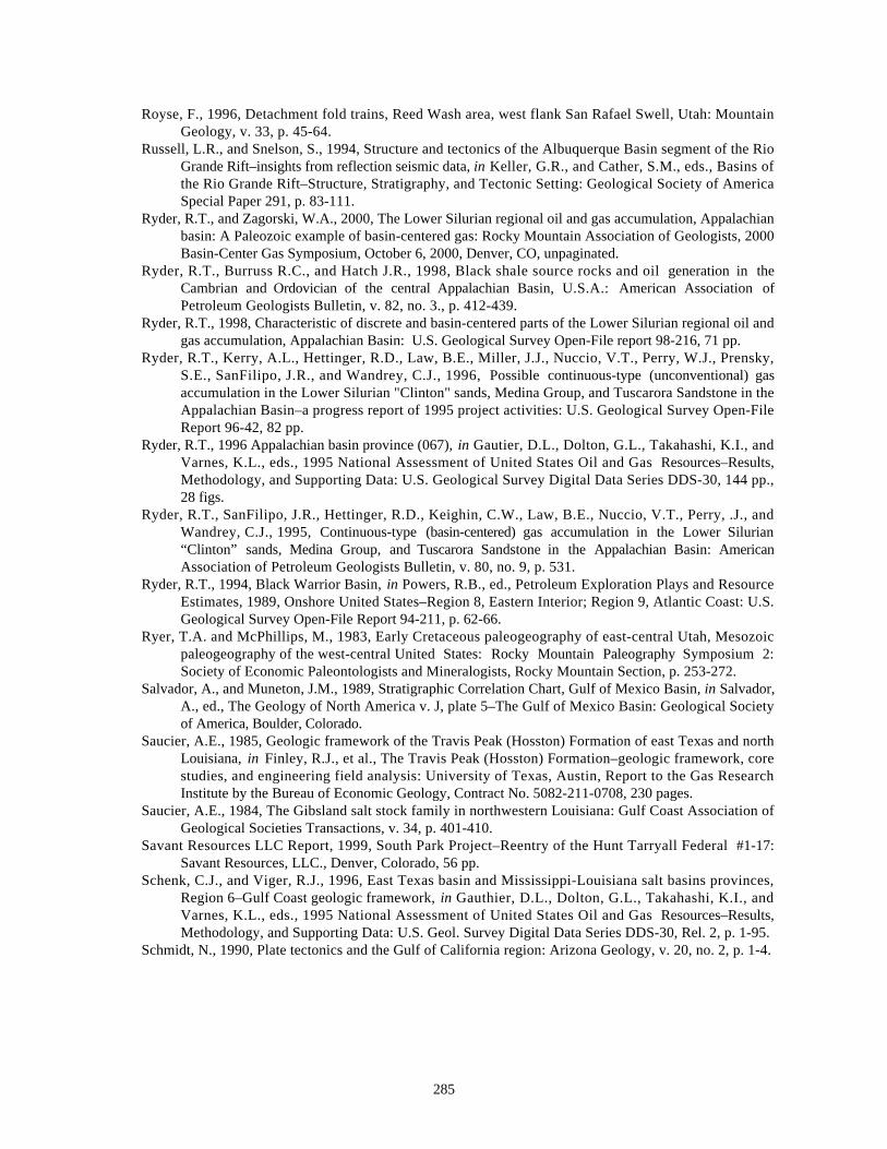
285
Royse, F., 1996, Detachment fold trains, Reed Wash area, west flank San Rafael Swell, Utah: MountainGeology, v. 33, p. 45-64.
Russell, L.R., and Snelson, S., 1994, Structure and tectonics of the Albuquerque Basin segment of the RioGrande Rift–insights from reflection seismic data, in Keller, G.R., and Cather, S.M., eds., Basins ofthe Rio Grande Rift–Structure, Stratigraphy, and Tectonic Setting: Geological Society of AmericaSpecial Paper 291, p. 83-111.
Ryder, R.T., and Zagorski, W.A., 2000, The Lower Silurian regional oil and gas accumulation, Appalachianbasin: A Paleozoic example of basin-centered gas: Rocky Mountain Association of Geologists, 2000Basin-Center Gas Symposium, October 6, 2000, Denver, CO, unpaginated.
Ryder, R.T., Burruss R.C., and Hatch J.R., 1998, Black shale source rocks and oil generation in theCambrian and Ordovician of the central Appalachian Basin, U.S.A.: American Association ofPetroleum Geologists Bulletin, v. 82, no. 3., p. 412-439.
Ryder, R.T., 1998, Characteristic of discrete and basin-centered parts of the Lower Silurian regional oil andgas accumulation, Appalachian Basin: U.S. Geological Survey Open-File report 98-216, 71 pp.
Ryder, R.T., Kerry, A.L., Hettinger, R.D., Law, B.E., Miller, J.J., Nuccio, V.T., Perry, W.J., Prensky,S.E., SanFilipo, J.R., and Wandrey, C.J., 1996, Possible continuous-type (unconventional) gasaccumulation in the Lower Silurian "Clinton" sands, Medina Group, and Tuscarora Sandstone in theAppalachian Basin–a progress report of 1995 project activities: U.S. Geological Survey Open-FileReport 96-42, 82 pp.
Ryder, R.T., 1996 Appalachian basin province (067), in Gautier, D.L., Dolton, G.L., Takahashi, K.I., andVarnes, K.L., eds., 1995 National Assessment of United States Oil and Gas Resources–Results,Methodology, and Supporting Data: U.S. Geological Survey Digital Data Series DDS-30, 144 pp.,28 figs.
Ryder, R.T., SanFilipo, J.R., Hettinger, R.D., Keighin, C.W., Law, B.E., Nuccio, V.T., Perry, .J., andWandrey, C.J., 1995, Continuous-type (basin-centered) gas accumulation in the Lower Silurian“Clinton” sands, Medina Group, and Tuscarora Sandstone in the Appalachian Basin: AmericanAssociation of Petroleum Geologists Bulletin, v. 80, no. 9, p. 531.
Ryder, R.T., 1994, Black Warrior Basin, in Powers, R.B., ed., Petroleum Exploration Plays and ResourceEstimates, 1989, Onshore United States–Region 8, Eastern Interior; Region 9, Atlantic Coast: U.S.Geological Survey Open-File Report 94-211, p. 62-66.
Ryer, T.A. and McPhillips, M., 1983, Early Cretaceous paleogeography of east-central Utah, Mesozoicpaleogeography of the west-central United States: Rocky Mountain Paleography Symposium 2:Society of Economic Paleontologists and Mineralogists, Rocky Mountain Section, p. 253-272.
Salvador, A., and Muneton, J.M., 1989, Stratigraphic Correlation Chart, Gulf of Mexico Basin, in Salvador,A., ed., The Geology of North America v. J, plate 5–The Gulf of Mexico Basin: Geological Societyof America, Boulder, Colorado.
Saucier, A.E., 1985, Geologic framework of the Travis Peak (Hosston) Formation of east Texas and northLouisiana, in Finley, R.J., et al., The Travis Peak (Hosston) Formation–geologic framework, corestudies, and engineering field analysis: University of Texas, Austin, Report to the Gas ResearchInstitute by the Bureau of Economic Geology, Contract No. 5082-211-0708, 230 pages.
Saucier, A.E., 1984, The Gibsland salt stock family in northwestern Louisiana: Gulf Coast Association ofGeological Societies Transactions, v. 34, p. 401-410.
Savant Resources LLC Report, 1999, South Park Project–Reentry of the Hunt Tarryall Federal #1-17:Savant Resources, LLC., Denver, Colorado, 56 pp.
Schenk, C.J., and Viger, R.J., 1996, East Texas basin and Mississippi-Louisiana salt basins provinces,Region 6–Gulf Coast geologic framework, in Gauthier, D.L., Dolton, G.L., Takahashi, K.I., andVarnes, K.L., eds., 1995 National Assessment of United States Oil and Gas Resources–Results,Methodology, and Supporting Data: U.S. Geol. Survey Digital Data Series DDS-30, Rel. 2, p. 1-95.
Schmidt, N., 1990, Plate tectonics and the Gulf of California region: Arizona Geology, v. 20, no. 2, p. 1-4.
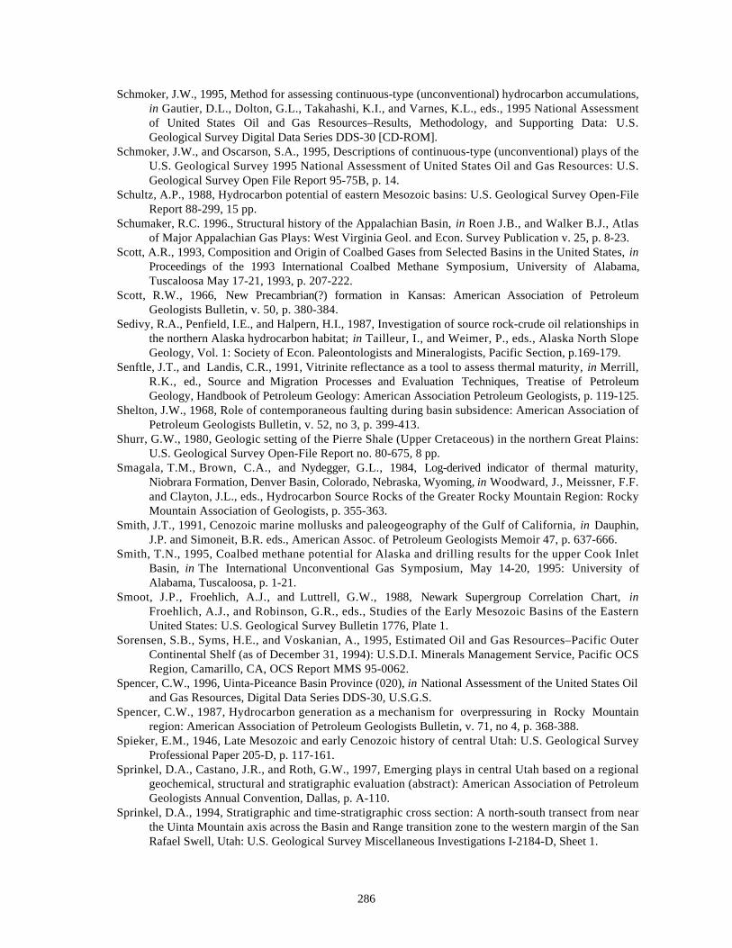
286
Schmoker, J.W., 1995, Method for assessing continuous-type (unconventional) hydrocarbon accumulations,in Gautier, D.L., Dolton, G.L., Takahashi, K.I., and Varnes, K.L., eds., 1995 National Assessmentof United States Oil and Gas Resources–Results, Methodology, and Supporting Data: U.S.Geological Survey Digital Data Series DDS-30 [CD-ROM].
Schmoker, J.W., and Oscarson, S.A., 1995, Descriptions of continuous-type (unconventional) plays of theU.S. Geological Survey 1995 National Assessment of United States Oil and Gas Resources: U.S.Geological Survey Open File Report 95-75B, p. 14.
Schultz, A.P., 1988, Hydrocarbon potential of eastern Mesozoic basins: U.S. Geological Survey Open-FileReport 88-299, 15 pp.
Schumaker, R.C. 1996., Structural history of the Appalachian Basin, in Roen J.B., and Walker B.J., Atlasof Major Appalachian Gas Plays: West Virginia Geol. and Econ. Survey Publication v. 25, p. 8-23.
Scott, A.R., 1993, Composition and Origin of Coalbed Gases from Selected Basins in the United States, inProceedings of the 1993 International Coalbed Methane Symposium, University of Alabama,Tuscaloosa May 17-21, 1993, p. 207-222.
Scott, R.W., 1966, New Precambrian(?) formation in Kansas: American Association of PetroleumGeologists Bulletin, v. 50, p. 380-384.
Sedivy, R.A., Penfield, I.E., and Halpern, H.I., 1987, Investigation of source rock-crude oil relationships inthe northern Alaska hydrocarbon habitat; in Tailleur, I., and Weimer, P., eds., Alaska North SlopeGeology, Vol. 1: Society of Econ. Paleontologists and Mineralogists, Pacific Section, p.169-179.
Senftle, J.T., and Landis, C.R., 1991, Vitrinite reflectance as a tool to assess thermal maturity, in Merrill,R.K., ed., Source and Migration Processes and Evaluation Techniques, Treatise of PetroleumGeology, Handbook of Petroleum Geology: American Association Petroleum Geologists, p. 119-125.
Shelton, J.W., 1968, Role of contemporaneous faulting during basin subsidence: American Association ofPetroleum Geologists Bulletin, v. 52, no 3, p. 399-413.
Shurr, G.W., 1980, Geologic setting of the Pierre Shale (Upper Cretaceous) in the northern Great Plains:U.S. Geological Survey Open-File Report no. 80-675, 8 pp.
Smagala, T.M., Brown, C.A., and Nydegger, G.L., 1984, Log-derived indicator of thermal maturity,Niobrara Formation, Denver Basin, Colorado, Nebraska, Wyoming, in Woodward, J., Meissner, F.F.and Clayton, J.L., eds., Hydrocarbon Source Rocks of the Greater Rocky Mountain Region: RockyMountain Association of Geologists, p. 355-363.
Smith, J.T., 1991, Cenozoic marine mollusks and paleogeography of the Gulf of California, in Dauphin,J.P. and Simoneit, B.R. eds., American Assoc. of Petroleum Geologists Memoir 47, p. 637-666.
Smith, T.N., 1995, Coalbed methane potential for Alaska and drilling results for the upper Cook InletBasin, in The International Unconventional Gas Symposium, May 14-20, 1995: University ofAlabama, Tuscaloosa, p. 1-21.
Smoot, J.P., Froehlich, A.J., and Luttrell, G.W., 1988, Newark Supergroup Correlation Chart, inFroehlich, A.J., and Robinson, G.R., eds., Studies of the Early Mesozoic Basins of the EasternUnited States: U.S. Geological Survey Bulletin 1776, Plate 1.
Sorensen, S.B., Syms, H.E., and Voskanian, A., 1995, Estimated Oil and Gas Resources–Pacific OuterContinental Shelf (as of December 31, 1994): U.S.D.I. Minerals Management Service, Pacific OCSRegion, Camarillo, CA, OCS Report MMS 95-0062.
Spencer, C.W., 1996, Uinta-Piceance Basin Province (020), in National Assessment of the United States Oiland Gas Resources, Digital Data Series DDS-30, U.S.G.S.
Spencer, C.W., 1987, Hydrocarbon generation as a mechanism for overpressuring in Rocky Mountainregion: American Association of Petroleum Geologists Bulletin, v. 71, no 4, p. 368-388.
Spieker, E.M., 1946, Late Mesozoic and early Cenozoic history of central Utah: U.S. Geological SurveyProfessional Paper 205-D, p. 117-161.
Sprinkel, D.A., Castano, J.R., and Roth, G.W., 1997, Emerging plays in central Utah based on a regionalgeochemical, structural and stratigraphic evaluation (abstract): American Association of PetroleumGeologists Annual Convention, Dallas, p. A-110.
Sprinkel, D.A., 1994, Stratigraphic and time-stratigraphic cross section: A north-south transect from nearthe Uinta Mountain axis across the Basin and Range transition zone to the western margin of the SanRafael Swell, Utah: U.S. Geological Survey Miscellaneous Investigations I-2184-D, Sheet 1.
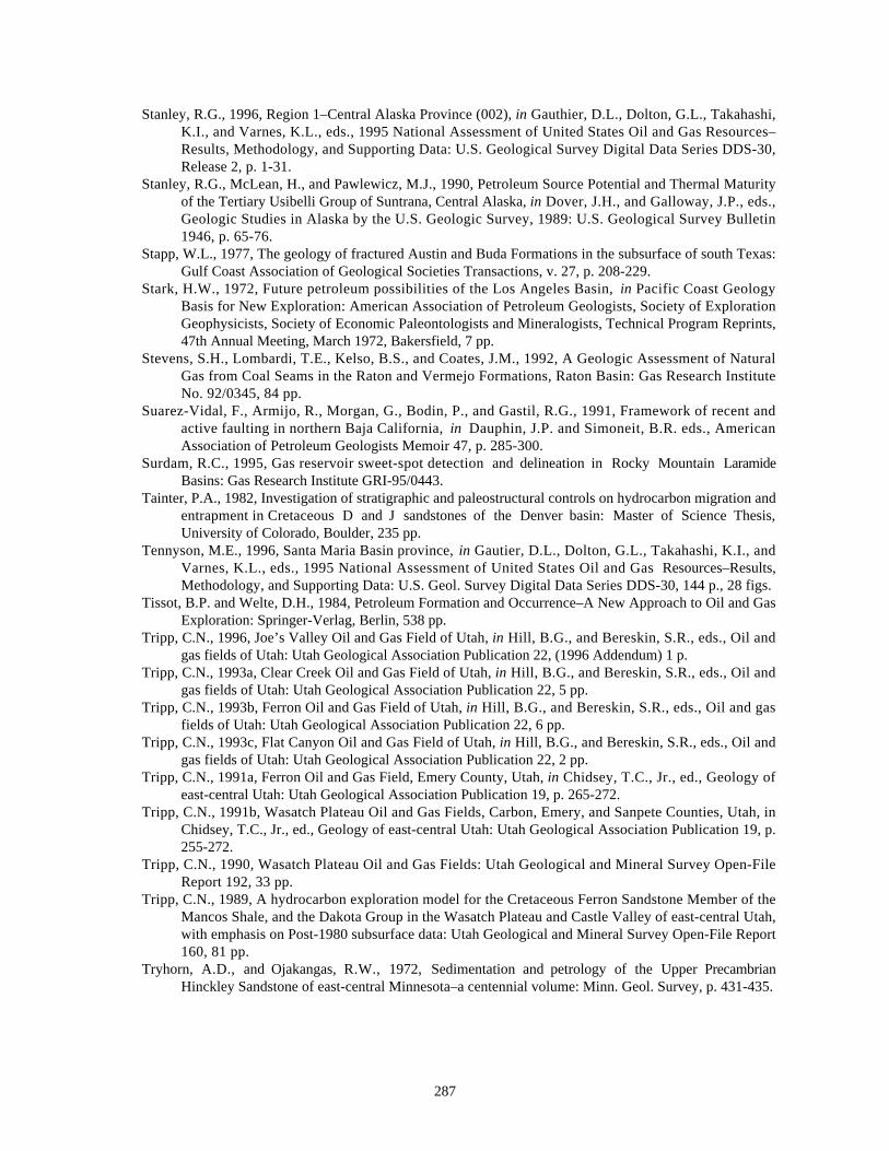
287
Stanley, R.G., 1996, Region 1–Central Alaska Province (002), in Gauthier, D.L., Dolton, G.L., Takahashi,K.I., and Varnes, K.L., eds., 1995 National Assessment of United States Oil and Gas Resources–Results, Methodology, and Supporting Data: U.S. Geological Survey Digital Data Series DDS-30,Release 2, p. 1-31.
Stanley, R.G., McLean, H., and Pawlewicz, M.J., 1990, Petroleum Source Potential and Thermal Maturityof the Tertiary Usibelli Group of Suntrana, Central Alaska, in Dover, J.H., and Galloway, J.P., eds.,Geologic Studies in Alaska by the U.S. Geologic Survey, 1989: U.S. Geological Survey Bulletin1946, p. 65-76.
Stapp, W.L., 1977, The geology of fractured Austin and Buda Formations in the subsurface of south Texas:Gulf Coast Association of Geological Societies Transactions, v. 27, p. 208-229.
Stark, H.W., 1972, Future petroleum possibilities of the Los Angeles Basin, in Pacific Coast GeologyBasis for New Exploration: American Association of Petroleum Geologists, Society of ExplorationGeophysicists, Society of Economic Paleontologists and Mineralogists, Technical Program Reprints,47th Annual Meeting, March 1972, Bakersfield, 7 pp.
Stevens, S.H., Lombardi, T.E., Kelso, B.S., and Coates, J.M., 1992, A Geologic Assessment of NaturalGas from Coal Seams in the Raton and Vermejo Formations, Raton Basin: Gas Research InstituteNo. 92/0345, 84 pp.
Suarez-Vidal, F., Armijo, R., Morgan, G., Bodin, P., and Gastil, R.G., 1991, Framework of recent andactive faulting in northern Baja California, in Dauphin, J.P. and Simoneit, B.R. eds., AmericanAssociation of Petroleum Geologists Memoir 47, p. 285-300.
Surdam, R.C., 1995, Gas reservoir sweet-spot detection and delineation in Rocky Mountain LaramideBasins: Gas Research Institute GRI-95/0443.
Tainter, P.A., 1982, Investigation of stratigraphic and paleostructural controls on hydrocarbon migration andentrapment in Cretaceous D and J sandstones of the Denver basin: Master of Science Thesis,University of Colorado, Boulder, 235 pp.
Tennyson, M.E., 1996, Santa Maria Basin province, in Gautier, D.L., Dolton, G.L., Takahashi, K.I., andVarnes, K.L., eds., 1995 National Assessment of United States Oil and Gas Resources–Results,Methodology, and Supporting Data: U.S. Geol. Survey Digital Data Series DDS-30, 144 p., 28 figs.
Tissot, B.P. and Welte, D.H., 1984, Petroleum Formation and Occurrence–A New Approach to Oil and GasExploration: Springer-Verlag, Berlin, 538 pp.
Tripp, C.N., 1996, Joe’s Valley Oil and Gas Field of Utah, in Hill, B.G., and Bereskin, S.R., eds., Oil andgas fields of Utah: Utah Geological Association Publication 22, (1996 Addendum) 1 p.
Tripp, C.N., 1993a, Clear Creek Oil and Gas Field of Utah, in Hill, B.G., and Bereskin, S.R., eds., Oil andgas fields of Utah: Utah Geological Association Publication 22, 5 pp.
Tripp, C.N., 1993b, Ferron Oil and Gas Field of Utah, in Hill, B.G., and Bereskin, S.R., eds., Oil and gasfields of Utah: Utah Geological Association Publication 22, 6 pp.
Tripp, C.N., 1993c, Flat Canyon Oil and Gas Field of Utah, in Hill, B.G., and Bereskin, S.R., eds., Oil andgas fields of Utah: Utah Geological Association Publication 22, 2 pp.
Tripp, C.N., 1991a, Ferron Oil and Gas Field, Emery County, Utah, in Chidsey, T.C., Jr., ed., Geology ofeast-central Utah: Utah Geological Association Publication 19, p. 265-272.
Tripp, C.N., 1991b, Wasatch Plateau Oil and Gas Fields, Carbon, Emery, and Sanpete Counties, Utah, inChidsey, T.C., Jr., ed., Geology of east-central Utah: Utah Geological Association Publication 19, p.255-272.
Tripp, C.N., 1990, Wasatch Plateau Oil and Gas Fields: Utah Geological and Mineral Survey Open-FileReport 192, 33 pp.
Tripp, C.N., 1989, A hydrocarbon exploration model for the Cretaceous Ferron Sandstone Member of theMancos Shale, and the Dakota Group in the Wasatch Plateau and Castle Valley of east-central Utah,with emphasis on Post-1980 subsurface data: Utah Geological and Mineral Survey Open-File Report160, 81 pp.
Tryhorn, A.D., and Ojakangas, R.W., 1972, Sedimentation and petrology of the Upper PrecambrianHinckley Sandstone of east-central Minnesota–a centennial volume: Minn. Geol. Survey, p. 431-435.
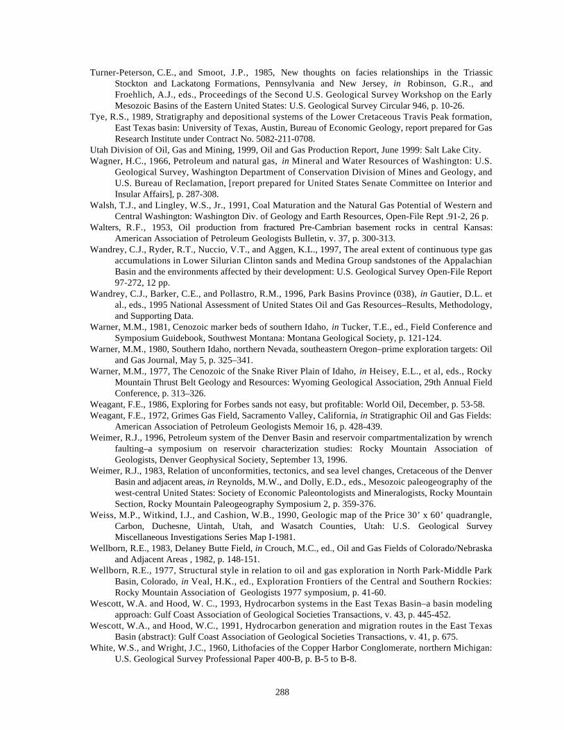
288
Turner-Peterson, C.E., and Smoot, J.P., 1985, New thoughts on facies relationships in the TriassicStockton and Lackatong Formations, Pennsylvania and New Jersey, in Robinson, G.R., andFroehlich, A.J., eds., Proceedings of the Second U.S. Geological Survey Workshop on the EarlyMesozoic Basins of the Eastern United States: U.S. Geological Survey Circular 946, p. 10-26.
Tye, R.S., 1989, Stratigraphy and depositional systems of the Lower Cretaceous Travis Peak formation,East Texas basin: University of Texas, Austin, Bureau of Economic Geology, report prepared for GasResearch Institute under Contract No. 5082-211-0708.
Utah Division of Oil, Gas and Mining, 1999, Oil and Gas Production Report, June 1999: Salt Lake City.Wagner, H.C., 1966, Petroleum and natural gas, in Mineral and Water Resources of Washington: U.S.
Geological Survey, Washington Department of Conservation Division of Mines and Geology, andU.S. Bureau of Reclamation, [report prepared for United States Senate Committee on Interior andInsular Affairs], p. 287-308.
Walsh, T.J., and Lingley, W.S., Jr., 1991, Coal Maturation and the Natural Gas Potential of Western andCentral Washington: Washington Div. of Geology and Earth Resources, Open-File Rept .91-2, 26 p.
Walters, R.F., 1953, Oil production from fractured Pre-Cambrian basement rocks in central Kansas:American Association of Petroleum Geologists Bulletin, v. 37, p. 300-313.
Wandrey, C.J., Ryder, R.T., Nuccio, V.T., and Aggen, K.L., 1997, The areal extent of continuous type gasaccumulations in Lower Silurian Clinton sands and Medina Group sandstones of the AppalachianBasin and the environments affected by their development: U.S. Geological Survey Open-File Report97-272, 12 pp.
Wandrey, C.J., Barker, C.E., and Pollastro, R.M., 1996, Park Basins Province (038), in Gautier, D.L. etal., eds., 1995 National Assessment of United States Oil and Gas Resources–Results, Methodology,and Supporting Data.
Warner, M.M., 1981, Cenozoic marker beds of southern Idaho, in Tucker, T.E., ed., Field Conference andSymposium Guidebook, Southwest Montana: Montana Geological Society, p. 121-124.
Warner, M.M., 1980, Southern Idaho, northern Nevada, southeastern Oregon–prime exploration targets: Oiland Gas Journal, May 5, p. 325–341.
Warner, M.M., 1977, The Cenozoic of the Snake River Plain of Idaho, in Heisey, E.L., et al, eds., RockyMountain Thrust Belt Geology and Resources: Wyoming Geological Association, 29th Annual FieldConference, p. 313–326.
Weagant, F.E., 1986, Exploring for Forbes sands not easy, but profitable: World Oil, December, p. 53-58.Weagant, F.E., 1972, Grimes Gas Field, Sacramento Valley, California, in Stratigraphic Oil and Gas Fields:
American Association of Petroleum Geologists Memoir 16, p. 428-439.Weimer, R.J., 1996, Petroleum system of the Denver Basin and reservoir compartmentalization by wrench
faulting–a symposium on reservoir characterization studies: Rocky Mountain Association ofGeologists, Denver Geophysical Society, September 13, 1996.
Weimer, R.J., 1983, Relation of unconformities, tectonics, and sea level changes, Cretaceous of the DenverBasin and adjacent areas, in Reynolds, M.W., and Dolly, E.D., eds., Mesozoic paleogeography of thewest-central United States: Society of Economic Paleontologists and Mineralogists, Rocky MountainSection, Rocky Mountain Paleogeography Symposium 2, p. 359-376.
Weiss, M.P., Witkind, I.J., and Cashion, W.B., 1990, Geologic map of the Price 30’ x 60’ quadrangle,Carbon, Duchesne, Uintah, Utah, and Wasatch Counties, Utah: U.S. Geological SurveyMiscellaneous Investigations Series Map I-1981.
Wellborn, R.E., 1983, Delaney Butte Field, in Crouch, M.C., ed., Oil and Gas Fields of Colorado/Nebraskaand Adjacent Areas , 1982, p. 148-151.
Wellborn, R.E., 1977, Structural style in relation to oil and gas exploration in North Park-Middle ParkBasin, Colorado, in Veal, H.K., ed., Exploration Frontiers of the Central and Southern Rockies:Rocky Mountain Association of Geologists 1977 symposium, p. 41-60.
Wescott, W.A. and Hood, W. C., 1993, Hydrocarbon systems in the East Texas Basin–a basin modelingapproach: Gulf Coast Association of Geological Societies Transactions, v. 43, p. 445-452.
Wescott, W.A., and Hood, W.C., 1991, Hydrocarbon generation and migration routes in the East TexasBasin (abstract): Gulf Coast Association of Geological Societies Transactions, v. 41, p. 675.
White, W.S., and Wright, J.C., 1960, Lithofacies of the Copper Harbor Conglomerate, northern Michigan:U.S. Geological Survey Professional Paper 400-B, p. B-5 to B-8.
289
Wickham, J.S., Roeder, D., and Briggs, G., 1976, Plate tectonics models for the Ouachita fold belt:Geological Society of America, Geology, v. 4, no. 3, p. 173-176.
Willis, G.C., 1999, The Utah thrust system-an overview, in Spangler, L.E., and Allen, C.J., Geology ofNorthern Utah and Vicinity: Utah Geological Association, Guidebook UGA-27, p. 2.
Wilson, M.S., Dyman, T.S., and Nuccio,V.F., in press, Is there a basin-center gas accumulation in theHanna basin, Wyoming?: in Nuccio, V.F., and Dyman, T.S., eds., Geologic Studies of Basin-CenterGas Systems: U.S. Geological Survey Bulletin 2184.
Winker, C.D., and Buffler, R.T., 1988, Paleogeographic Evolution of Early Deep-Water Gulf of Mexico andMargins, Jurassic to Middle Cretaceous (Comanchean): American Association of PetroleumGeologists Bulletin, v. 72, p. 318-346.
Winter, B.L., Valley, J.W., Simo, J.A., Nadon, G.C., and Johnson, C.M., 1995, Hydraulic seals and theirorigin–evidence from the stable isotope geochemistry of dolomites in the Middle Ordovician St. PeterSandstone, Michigan Basin: American Association of Petroleum Geologists Bulletin. v. 79, p. 30-48.
Wood, M.L., and Walper, M.L., 1974, The evolution of the Western Interior basins and the Gulf of Mexico:Gulf Coast Association of Geological Societies Transactions, v. 24, p. 31-41.
Wood, S.H., 1994, Seismic expression and geological significance of a lacustrine delta in Neogene depositsof the western Snake River plain, Idaho: American Association Petroleum Geologists Bulletin. v. 78,no. 1, p. 102-121.
Woodward, J., Meissner, F.F. and Clayton, J.L., 1984, eds., Hydrocarbon Source Rocks of the GreaterRocky Mountain Region: Rocky Mountain Association of Geologists, Denver, p. 365-368.
Woodward, L.A., and Snyder, D.O., 1976, Structural framework of the southern Raton Basin, New Mexico,in Ewing, R.C., and Kues, B.S., eds., Guidebook of Vermejo Park, Northeastern New Mexico: NewMexico Geological Society 27th Field Conference Guidebook, p. 125-127.
Wright, W.F., 1979, Petroleum Geology of the Permian Basin: West Texas Geological Society, Midland,Texas, Publ. No. 79-71, 98 pp.
Yerkes, R.F., McCulloh, T.H., Schoellhame, J.E., and Vedder, J.G., 1965, Geology of the Los AngelesBasin, California–an Introduction: U.S. Geological Survey Professional Paper 420-A, 57 pp.
Young, R.G., 1960, Dakota Group of Colorado Plateau: American Association of Petroleum GeologistsBulletin v. 44, p. 156-194.
Zieglar, D.L. and Spotts, J.H., 1978, Reservoir and source bed history of the Great Valley, California:American Association of Petroleum Geologists Bulletin, v. 62, no. 5, p. 813-826.
290
SELECTED BIBLIOGRAPHY
Allison, M.L. et al, 1993, Grassy Trail Oil and Gas Field of Utah: Utah Geological AssociationPublication 22, 4 pp.
Al-Shaieb, Z., Puckette, J.O., Abdalla, A.A., Tigert, V. and Ortoleva, P.J., 1997, The banded characterof pressure seals, in Gas Research Institute Workshop, Compartmentalization of OverpressuredReservoirs in the Anadarko Basin–Implications for Exploration and Development: Gas ResearchInstitute, Oklahoma City, p. 30-46.
Bahr, J.M., Moline, G.R., and Nadon, G., 1994, Anomalous pressures in the deep Michigan Basin, inOrteleva, P., ed., Basin Compartments and Seals: American Association of PetroleumGeologists Memoir 61, p. 153-166.
Bebout, D.G., White, W.A., Hentz, T.F., Grasmick, M.K., Woodward, M., Parham, K.D., Bingham,T.L., Brown, R.L., Campbell, J.A., Northcutt, R.A., Fisher, W.L., and Mendenhall, J.M.,1993, Atlas of Major Midcontinent Gas Reservoirs: Gas Research Institute Document No. GRI-93/0260.1, GRI Contract Number 5088-215-1771, University of Texas at Austin, Bureau ofEconomic Geology, Arkansas Geological Commission, Oklahoma Geological Survey, KansasGeological Survey, 91 pp.
Black, B.A. and Hiss, W.L., 1974, Structure and stratigraphy in the vicinity of the Shell Oil Co. SantaFe Pacific No. 1 test well, southern Sandoval County, New Mexico, Ghost Ranch (central-northern New Mexico), New Mexico Geological Society Guidebook, 25th Field Conference, p.365-370.
Blasko, D., Wegner, W., and Morris, J., 1972, Oil fields and crude oil characteristics, Cook InletBasin, Alaska: U.S. Bureau of Mines Report of Investigations No. 7688.
Bostick, N.H. and Pawlewicz, M.J., 1984, Regional variation of vitrinite reflectance of the PierreShale (Upper Cretaceous) in mountain basins and along the eastern Rocky Mountain front,Colorado, in Woodward, J., Meissner, F.F. and Clayton, J.L., eds., Hydrocarbon Source Rocksof the Greater Rocky Mountain Region: Rocky Mountain Association of Geologists, p. 393-399.
Bredehoeft, J.D., Wesley, J.B., and Fouch, T.D., 1994, Simulations of the origin of fluid pressure,fracture generation and the movement of fluids in the Uinta Basin, Utah: American Associationof Petroleum Geologists Bulletin v. 78, p. 1729-1747.
Brown, K.W., and Ritzma, H.R., 1982, Oil and Gas Fields and Pipelines of Utah: Utah Geological andMineral Survey, Map 61, scale 1:750,000.
Cardott, B.J., and Lambert, M.W., 1985, Thermal maturation by vitrinite reflectance of WoodfordShale, Anadarko Basin, Oklahoma: American Association of Petroleum Geologists Bulletin, v.69, no. 11, p. 1982-1998.
Carlton, B.E., Tepper, D.H., Goodman W.M., LoDuca, S.T., and Eckert, B-Y., 1995, Revisedstratigraphy and correlations of the Niagaran Provincial Series (Medina, Clinton, and LockportGroups) in the type area of western New York: U.S. Geological Survey Bulletin 2086, 66 pp.
Cobban, W.A., Erdmann, C.E., Lemke, R.W., and Maughan, E.K., 1976, Type sections andstratigraphy of the members of the Blackleaf and Marias River Formations (Cretaceous) of theSweetgrass Arch, Montana: U.S. Geological Survey Professional Paper 974.
Cramer, R.D., Gatlin, L., and Wessman, H.G., eds., 1963, Oil and Gas Fields of Oklahoma:Oklahoma City Geological Society, Reference Report, Volume 1.
Davis, F.D. and Doelling, H.H., 1977, Methane content of Utah coals: Utah Geological and MineralSurvey Open-File Report 24, 13 pp.
Durhnam, L.S., 1992, Horizontal action heats up in Louisiana: World Oil, v. 213, no. 6, p. 39-42.Dwights, 1999, Discover Rocky Mountain Well History Data Base (commercial).Freezon, S.E., and Finn, T.M., 1988, Map of Sedimentary Basins in the Coterminous United States:
U.S. Geological Survey Map OM-223.Gardner, M.H., and Cross, T.A., 1994, Middle Cretaceous Paleogeography of Utah, in Mesozoic
Systems of the Rocky Mountain Region, U.S.A.: Society of Economic Paleontologists andMineralogists, Rocky Mountain Section, p. 471-502.
291
Gribi, E.A., 1959, Oil developments and prospects of the south Sweetgrass Arch area, in Hammond,C.R., and Trap, H., Jr., eds., Billings Geological Society 10th Annual Field Conference.
Gross, T.L., and Keller, G.V., 1979, Geothermal energy in the Basin and Range Province, in Newman,G.W., and Goode, H.D., eds, Guidebook, 1979 Basin and Range Symposium: Rocky MountainAssociation of Geologists and Utah Geological Society.
Gryc, G., ed., 1988, Geology and Exploration of the National Petroleum Reserve in Alaska, 1974-1982: U. S. Geological Survey Professional Paper 1399, 940 pp.
Herbaly, E.L., 1974, Petroleum geology of the Sweetgrass Arch, Alberta: American Association ofPetroleum Geologists Bulletin, v. 50, p. 2118-2149.
Higley, D.K., Gautier, D.L., and Pawlewicz, M.J., 1992, Influence of regional heat flow variation onthermal maturity of the Lower Cretaceous Muddy ("J") Sandstone, Denver Basin, Colorado, inMagoon, L.B., ed., The Petroleum System Status of Research and Methods: U.S. GeologicalSurvey Bulletin 2007, p. 66-69.
Horan, E.P., 1990, Natural gas distribution, entrapment, and production phenomenon within the UpperCretaceous Forbes Formation depositional system, Northern Sacramento Basin, California:American Association of Petroleum Geologists Bulletin v.74, n. 5, p. 677 (abstract).
Howell, D.G., 1996, Kandik basin, in Gauthier, D.L., Dolton, G.L., Takahashi, K.I., and Varnes,K.L., eds., 1995 National Assessment of United States Oil and Gas Resources-Results,Methodology, and Supporting Data: U.S. Geological Survey Digital Data Series DDS-30,Release 2, p. 22-37.
Johnson, E., 1961, Joe’s Valley Gas Field, in Oil and Gas Fields of Utah: Intermountain Associationof Petroleum Geologists Symposium, 3 pp.
Joseph, R.A., 1993, Planning lessens problems, gets benefits of underbalance: Oil and Gas Journal,March 20, 1995.
Katich, Jr., P.J., 1954, Cretaceous and Early Tertiary stratigraphy of central and south-central Utahwith emphasis on the Wasatch Plateau area–geology of portions of the high plateaus andadjacent canyon lands, central and south-central Utah: Intermountain Association of PetroleumGeologists Fifth Annual Field Conference, p. 42-54.
Kearney, M.W., 1984, Subsurface stratigraphy of Medina Group (Lower Silurian), Clinton Group(Lower to Upper Silurian), and Lockport Group (Upper Silurian) of New York: AmericanAssociation of Petroleum Geologists Bulletin, v. 68, no. 12, p. 1921-1922.
Kluth, C.F. and Schaftenaar, C.H., 1994, Depth and geometry of the northern Rio Grande Rift in theSan Luis Basin, south-central Colorado: Geological Society of America Special Paper 291, p.27-37.
Laine, M.D. and Staley, D., 1991, Summary of oil and gas exploration and production in Carbon,Emery and Sanpete Counties, east-central Utah, in Geology of East-Central Utah: UtahGeological Association Publication 19, p. 227-235.
Libby-French, J., 1985, Play analysis of undiscovered oil and gas resources on onshore federal lands–Phase One, Atlantic Coastal Plain: United States Geological Survey Open-File Report 85-269,17 p.
Lucas, P.T., and Drexler, J.M., 1976, Altamont-Bluebell, a major, naturally fractured stratigraphictrap, Uinta Basin, Utah, in North American Oil and Gas Fields: American Association ofPetroleum Geologists Memoir 24, p. 121-135.
Mantheny, J.P. and Picard, M.D., 1985, Sedimentology and depositional environments of the EmerySandstone Member of the Mancos Shale, Emery and Sevier Counties, Utah: The MountainGeologist, v.22, no. 3, p.94-109.
McCulloh, R.P., and Purcell, M. D., 1983, Hydropressure tongues within regionally geopressuredLower Tuscaloosa Sandstone, Tuscaloosa Trend, Louisiana: Gulf Coast Association ofGeological Societies Transactions, v. 33, p. 153-159.
McGowen, M.K., and Harris, D.W., 1984, Cotton Valley (Upper Jurassic) and Hosston (UpperCretaceous) depositional systems and their influence on salt tectonics in the East Texas basin:University of Texas at Austin, Bureau of Economic Geology, Geological Circular 84-5, 41 pp.
292
Meissner, F.F., 1984, Cretaceous and Lower Tertiary coals as sources for gas accumulations in theRocky Mountain area, in Woodward, J., Meissner, F.F. and Clayton, J.L., eds., HydrocarbonSource Rocks of the Greater Rocky Mountain Region: Rocky Mountain Association ofGeologists, p. 401-431.
Meylan, M.A., 1997, Controls on the Distribution of Oil and Gas, Mesozoic and Cenozoic ofMississippi: American Association of Petroleum Geologists Bulletin, v. 89, no. 9, p. 1583.
Moore, D.W., 1991, Stratigraphy, sedimentology and provenance of the Lower Campanian Forbes andMarsh Creek Formations, southern Sacramento and northern San Joaquin Basins, California:Masters Thesis, San Jose State University, California (abstract).
Ortlieb, L., 1991, Quaternary vertical movements along the coasts of Baja California and Sonora, inDauphin, J.P. and Simoneit, B.R., eds, AAPG Memoir 47: American Association of PetroleumGeologists, p. 447-480.
Palmer, S.E., 1984, Hydrocarbon source potential of organic facies of the lacustrine Elko Formation(Eocene-Oligocene), northeast Nevada, in Woodward, J., Meissner, F.F., and Clayton, J.L., eds.,Hydrocarbon Source Rocks of the Greater Rocky Mountain Region: Rocky MountainAssociation of Geologists.
Peterson, J.A., 1987, Pre-thrusting regional stratigraphy and paleotectonics, northern RockyMountains and adjacent Cordilleran shelf, U.S., in Miller, W.R., ed., 1987, The Thrust BeltRevisited: Wyoming Geological Association, Casper, p. 17–26.
Pollastro, R.M., 1992, Natural fractures, composition, cyclicity, and diagenesis of the UpperCretaceous Niobrara Formation, Berthoud Field, Colorado, in Schmoker, J.W., Coalson, E.B.,Brown, C.A., eds., Geological Studies Relevant to Horizontal Drilling–Examples from WesternNorth America: Rocky Mountain Association of Geologists, p. 243-255.
Preston, D., ed., 1961, Oil and Gas Fields of Utah: Intermountain Association of PetroleumGeologists.
Quigley, D., 1961, Ferron Gas Field: Intermountain Association of Petroleum GeologistsSymposium, Oil and Gas Fields of Utah, 4 pp.
Reid, J.W., 1954, The structural and stratigraphic history of the Carboniferous (Mississipian andPennsylvanian) of the Wasatch Plateau and environs–geology of portions of the high plateausand adjacent canyon lands, central and south-central Utah: Intermountain Association ofPetroleum Geologists Fifth Annual Field Conference, p. 18-20.
Salyards, S.L. and Ni, J.F., 1994, Variation in paleomagnetic rotations and kinematics of the north-central Rio Grande Rift, New Mexico: Geological Society of America Special Paper 291, p. 59-71.
Shirley, K., 1995, An oil find that was good as gold: American Association of Petroleum Geologists,Explorer, v.16, no. 7, p. 1,8-9.
Skelton, J.H., 1992, Louisiana horizontal well taps oil in area of salt-related fracturing: Oil and GasJournal, v. 90, no. 27, p. 88-90.
Sohl, N.F., 1991, Upper Cretaceous, in Salvador, A., The Gulf of Mexico Basin, The Geology ofNorth America, Vol. J: Geological Society of America, p. 205-244.
Speiker, E.D., 1954, Structural history–geology of portions of the high plateaus and adjacent canyonlands central and south-central Utah: Intermountain Association of Petroleum Geologists FifthAnnual Field Conference, p. 9-14.
Suek, D.H., 1999, Personal communication, Black Coral, LLC, Denver, Colorado.Surdham, R.C., 1994, Detection and delineation of anomalously pressured gas accumulations in Rocky
Mountain Laramide basins: Gas Research Institute, Rocky Mountain Association of Geologists,Denver, Gas Forum Notes.
Tabet, D., 1996, Drunkard’s Wash oil and gas field of Utah: Utah Geological Association Publication22 (Addendum 1996), 2 pp.
Thomas, M.A., 1993, Subnormal fluid pressure in the Clinton sandstone of eastern Ohio: unpublishedPh.D. thesis, Kent State University, 111 pp.
United States Geological Survey National Oil and Gas Resource Assessment Team, 1995, 1995National Assessment of United States Oil and Gas Resources: U.S. Geological Survey Circular1118, 20 pp.
293
Villien, A., 1986, Thrusting and synorogenic sedimentation in central Utah–paleotectonics andsedimentation in the Rocky Mountain Region, United States: American Association ofPetroleum Geologists Memoir 41, p. 281-307.
Walton, P.T., 1954, Wasatch Plateau Gas Fields, Utah, in Geology of portions of the high plateausand adjacent canyon lands, central and south-central Utah: Intermountain Association ofPetroleum Geologists Fifth Annual Field Conference, p. 79-85.
Wang, H.F., Crowley, K.D., and Nadon, G.C., 1994, Thermal history of the Michigan Basin fromapatite fission-track analysis and vitrinite reflectance, in Orteleva, P., ed., Basin Compartmentsand Seals: American Association of Petroleum Geologists Memoir 61, p. 167-177.
White, H.G., 1986, Engineering and production characteristics of oil and gas wells located in the BlackWarrior Basin of Alabama: Geological Survey of Alabama, Tuscaloosa, Oil and Gas Report no.11.
Witkind, I.J. and Page, W.R., 1984, Origin and significance of the Wasatch and Valley Mountainsmonoclines, Sanpete-Sevier Valley area, central Utah: The Mountain Geologist, v. 21 no. 4, p.143-156.
Wolf, T., 1995, Colorado’s Sangre de Cristo Mountains, University of Colorado Press, 339 pp.Woodard, G.D., 1974, Redefinition of Cenozoic stratigraphic column in Split Mountain Gorge,
Imperial Valley, California: American Association of Petroleum Geologists Bulletin, v. 58, no.3, p. 521-539.
Zigler, J.L., and Nilsen, T.H., 1984, Geochemistry of coal from the Dutch Creek Siltstone Member ofthe Hornbrook Formation, Northern California, in Nilsen, T.H., ed. Geology of the UpperCretaceous Hornbrook Formation, Oregon and California: Society of Economic Paleontologistsand Mineralogists, Pacific Section, v. 42, p. 123-127.
294
APPENDIX I:
PHASE II ABSTRACTS
Potential for a Basin-Center Gas Accumulation in the Albuquerque Basin, New Mexico
The potential that a basin-center or continuous-type gas accumulation is present in the Albuquerque Basin incentral New Mexico was investigated. The Albuquerque Basin is one of the many rift basins that make up theRio Grand Rift system, an area of active extension from Oligocene to recent time. The basin is significantlydifferent from other Rocky Mountain basins that contain basin-centered gas accumulation because it is activelysubsiding and is at near maximum burial and heating conditions at the present time. Burial reconstructionssuggest that Cretaceous-age source rocks began to generate gas in the deeper parts of the basin about 20 millionyears ago and are still generating large amounts of gas. High mud weights are typically used while drilling theCretaceous interval in the deeper areas of the basin suggesting some degree of overpressuring. Gas shows arecommonly reported while drilling through the Cretaceous interval; however, attempts to complete gas wells inthe Cretaceous have resulted in sub-economic quantities of gas, primarily because of low permeability. Littlewater has been reported. All of these characteristics suggest that a basin-center gas accumulation of some degreeis present in the Albuquerque Basin.
Is There a Basin-Center Gas Accumulation In the Deep Anadarko Basin?
Well data, formation test results and published studies of abnormal pressures, methane isotopes and thermalmaturity were reviewed to evaluate the possibility that a basin-center gas accumulation might exist within theregionally overpressured Mississippian and Pennsylvanian-age Atoka, Morrow and Springer Groups or in theMississippian and Devonian-age Woodford Shale in the central Anadarko basin, Oklahoma.
The Woodford Shale is a laterally extensive, organic-rich source rock which has passed completely into the gasgeneration window in the deepest parts of the basin, but it does not appear to have developed overpressures on aregional scale. A review of drilling mud weights and pressure data indicate that the Woodford Shale-HuntonGroup interval has generally been drilled with 9 to 10.5 ppg mud and appears to be normally to subnormallypressured throughout most of the central basin. The underlying Hunton Group contains high permeability zoneswhich frequently produce subnormally or normally pressured salt water. Hydrocarbons expelled from theWoodford Shale may have migrated downward into the Hunton aquifer and then moved laterally into structuraland stratigraphic traps. Two isolated overpressured compartments were identified where high mud weights andunusual casing designs were used for the Woodford section. These appear to be uplifted fault blocks wherestructural juxtaposition of the Woodford Shale and overpressured Springer shales may have locally modified thetypical plumbing system. The Woodford Shale does not appear to fit the basin-center gas model on a regionalscale.
The Atoka-Morrow-Springer section has many characteristics of known basin-center gas accumulations,including mature, gas-prone source rocks, temperatures greater than 200° F, severe overpressures, tight sandstonereservoirs, and extensive gas production. However, formation test data and published descriptions of known gasfields reveal numerous examples of gas-water contacts and water production within the overpressured section.Most commercial gas accumulations have been found in traditional structural and/or stratigraphic traps, butmany of the known gas reservoirs are water-saturated below distinct gas-water contacts. The available porosity inthe reservoirs was apparently not fully charged with gas. Perhaps the source rocks were not rich enough, orperhaps they cooled down and ceased gas expulsion too early, so that the porosity available in the numeroussandstones was not completely gas-saturated. Depending on current interpretations of just how much moveablewater is allowable in a ‘continuous-type’ gas accumulation, the overpressured Atoka-Morrow-Springer sectiondoes not quite fit the basin-center gas model on a regional scale.
295
Several reservoir zones within the deep Anadarko Basin may be completely gas-saturated on a local scale. Welldata and formation tests at North Broxton Field (T. 6 N., R. 12 W., Caddo County, Oklahoma) and Elk CityField (T. 10 N., R. 20 - 21 W., Washita and Beckham Counties, Oklahoma) indicate severe overpressures, hightemperatures, prolific gas production and almost no water production from the Springer section at depths ofapproximately 18,500 to 20,500 ft. Further study of formation test results and detailed log analyses arerecommended to determine if the deep Springer section might contain a small-scale basin-center gasaccumulation.
Is There a Basin-Center Gas Accumulation in the Columbia Basin (Pasco Basin), CentralWashington?
Well data, vitrinite analyses and previous geologic literature were examined to determine if the sparsely drilledPasco basin in central Washington might contain a basin-center gas accumulation similar to those found inseveral Rocky Mountain basins. The limited geologic data available to the public show that many pre-requisitesare present, including abnormal pressure gradients, thermally mature source rocks, high temperatures, abundantshows of natural gas, and tight sandstone reservoirs. However the results of twenty formation tests conducted inseveral deep exploration wells indicate that water-bearing zones have been encountered frequently. With theexception of a 1,850 ft thick section in the Roslyn Formation in the Shell Yakima Mineral Co. No. 1-33 wellwhich might be gas-saturated, the test data indicate widespread occurences of gassy formation water, and severalzones which produced water at high rates (> 50 barrels of water per day). The sedimentary section does notappear to be extensively gas-saturated.
The Pasco basin appears to be almost, but not quite a basin-center gas accumulation, with adequatetemperatures, thermally mature, gas-prone source rocks, overpressure and gas shows. But the formation testresults indicate too much water and not enough gas to completely match the definition. The volume of gasexpelled from the source rocks may have been inadequate to effectively de-water the reservoir section. AMiocene-age regional hydrothermal event may have altered the plumbing of the basin.
Is There a Basin-Center Gas Accumulation in Cotton Valley Group Sandstones, GulfCoast Basin, USA?
In 1995 the USGS assessed one oil and two conventional gas plays and one basin-center gas play inCretaceous/Jurassic Cotton Valley sandstones in the onshore northern Gulf of Mexico basin. Detailed evaluationof geologic and production data provides new insights into these Cotton Valley plays.
Two Cotton Valley sandstone trends are identified based on reservoir properties and gas-productioncharacteristics. Transgressive blanket sandstones across northern Louisiana have relatively high porosity andpermeability and do not require fracture stimulation to produce gas at commercial rates. South of this trend, andextending westward into east Texas, massive sandstones of the Cotton Valley exhibit low porosity andpermeability and require fracture stimulation.
Pressure gradients throughout most of both trends are normal, which is not characteristic of basin center gasaccumulations. Presence of gas-water contacts in at least seven fields across the blanket-sandstone trend togetherwith relatively high permeabilities and high gas-production rates without fracture stimulation indicate that fieldsin this trend are conventional. Within the tight, massive-sandstone trend, however, permeability is sufficientlylow that gas-water transition zones are vertically extensive and gas-water contacts poorly defined. Withincreasing depth through these transition zones, gas saturation decreases and water saturation increases untileventually gas saturations become sufficiently low that, in terms of cumulative production, wells become non-
296
commercial. Interpreted presence of gas-water contacts within the tight, massive Cotton Valley sandstone trendsuggests that accumulations in this trend are also conventional, and that a basin center gas accumulation doesnot exist within the Cotton Valley Sandstone in the northern Gulf basin.
Is There a Basin-Center Gas Accumulation in the Ordovician-Age Glenwood Formationand St. Peter Sandstone, Central Michigan Basin ?
Well data, structure maps, previous studies of abnormal pressures and thermal maturity, and publisheddescriptions of gas fields were evaluated to determine if a basin-center gas accumulation might exist within theOrdovician-age Glenwood Formation and St. Peter Sandstone in the Michigan basin. The Glenwood-St. Petersection has several characteristics of typical basin-center gas accumulations, including thermally mature sourcerocks, low porosity sandstone reservoirs, extensive overpressure and extensive production of dry gas andcondensate.
Well histories and data from more than 100 drill-stem tests reveal that many wells recovered significant volumesof salt water or gassy salt water with high chloride content (230,000 – 270,000 ppm Cl-) from the Glenwood-St. Peter interval. Pressure gradients range from 0.4 to 0.56 psi/ft, indicating normal pressures to moderateoverpressures. Core descriptions indicate fair porosity (4 to 13 percent, average 9 percent) within the St. PeterSandstone. Permeabilities vary widely, ranging from <0.1 md to 750 md, with 11 to 88 md in some thinsandstone lenses. High permeabilities are also indicated by the large amounts of water recovered in some of thedrill-stem tests. Permeabilities as high as these are seldom found in typical basin-center gas accumulations.
The sixteen gas fields which produce from the Glenwood Formation and/or St. Peter Sandstone are all locatedwithin anticlinal structures. Most of these gas accumulations have distinct gas-water contacts, and many areflanked by abandoned wells which tested water from the Glenwood-St. Peter section in low structural positions.Some of the traps appear to be incompletely filled with gas. Significant water production and strong water driveshave been noted in many of the published field descriptions. Reservoir temperatures are generally lower than190° F. Reservoir pressure gradients range from near-normal (0.4 psi/ft) to moderately overpressured (0.56psi/ft).
Regional structure maps indicate a relatively uncomplicated basin structure lacking major transverse fault zonesor fault-bounded pressure compartments. The salt water system in the Glenwood-St. Peter interval probablyextends throughout the central basin. Perhaps the Cambrian-Ordovician source rocks were not thick or richenough and did not expel enough hydrocarbons to fully saturate the available porosity with gas, or perhaps theycooled down and ceased gas expulsion too early. The Glenwood-St. Peter section has not been completelysaturated with gas. Based on analysis of well data and field descriptions, the Glenwood-St. Peter gas system is not a basin-center gas accumulation.
Potential for a Basin-Center Gas Accumulation in the Raton Basin, Colorado and NewMexico
The Raton Basin appears to contain a significant continuous or basin-center type gas accumulation in sandstonesof the Upper Cretaceous Trinidad Sandstone and Vermejo Formation and Upper Cretaceous and Paleocene RatonFormation. The accumulation is underpressured and occurs at comparatively shallow (< 3,500 ft) depths. Thesandstones are interbedded with coal beds that are currently being developed for coalbed methane, and the coalsare the likely source for gas found in the sandstones. Based on analog comparisons with other Rocky Mountainbasins, relatively water-free production should occur where levels of thermal maturity in the coals exceed a
297
vitrinite reflectance value of 1.1 percent. This level of thermal maturity occurs over much of the central part ofthe Raton Basin. Because of the shallow depths, some of the accumulation has probably been degraded bysurface water invasion.
Does the Forbes Formation in the Sacramento Basin Contain a Basin-Center GasAccumulation?
Well data, structural cross sections and published studies of abnormal pressures, methane isotopes, vitrinitereflectance measurements and thermal maturity were evaluated to determine if a basin-center gas accumulationmight exist within the Cretaceous-age Forbes Formation in the Sacramento Basin, California. The ForbesFormation is a mud-rich turbidite system with thick marine shale deposits and discontinuous sandstone lenses.At least twenty-seven natural gas fields have been discovered in the Forbes Formation, mainly in traditionalstructural and stratigraphic traps with distinct gas-water contacts.
Previous studies of source rock and organic content show that the Forbes Formation contains low levels of gas-prone organic material, mainly dispersed fragments of lignite, wood and land plants. A recent study of theDobbins Shale notes extensive bioturbation and lack of laminations, indicating oxidizing conditions. Studies ofsource rock quality in outcrops along the western flank of the basin found low organic content throughout theUpper Cretaceous section. Thermal gradients and bottom hole temperatures are unusually low in the SacramentoBasin. Published vitrinite reflectance profiles show that the Forbes is immature to sub-mature throughout mostof the basin. All Forbes gas production comes from thermally immature sandstone reservoirs with lowtemperatures (< 190° F) and relatively high porosities (17 – 30 percent). The gas produced from most Forbesreservoirs is primarily methane, with variable amounts of nitrogen. Isotope analyses indicate that the methane isa mixture of immature, biogenic methane and overmature, thermogenic methane, which apparently migratedlong distances from a deep gas kitchen, probably dissolved in formation waters under high pressure.
The lower Forbes Formation and underlying Dobbins Shale are overpressured throughout the central andsouthern parts of the basin. Drill stem test data from the Grimes, Buckeye, Kirk, and Arbuckle Gas Fields andthe Rumsey Hills area indicate abnormal pressure gradients ranging from 0.5 to 0.92 psi/ft in the Forbes. Theoverpressuring fluid is usually gassy salt water, not hydrocarbons. No evidence of sub-normal pressure wasobserved. Previous authors have suggested that the primary causes of the overpressures in the Forbes are tectoniccompression and aquathermal pressuring, rather than hydrocarbon generation. The Forbes appears to beregionally water-saturated, except for localized structural/stratigraphic gas traps. The Forbes has not beenextensively de-watered by local gas generation. The basin-center gas model does not appear to fit the ForbesFormation in the central, northern and eastern parts of the Sacramento Basin.
Previous authors have suggested that the Delta Depocenter, a deep wrench basin in the southwestern SacramentoBasin, may be the deep gas kitchen where much of the basin’s gas was generated. Structural cross sections showthat the lower Forbes Formation and Dobbins Shale may be buried 18,000 to 20,000 ft deep in this structuraldepression. Older source rocks such as the Upper Cretaceous-age Funks and Yolo Shales may be buried as deepas 23,000 to 26,000 ft. A thermal maturity model was constructed for the Delta Depocenter, using Basin-Modsoftware, published cross sections, vitrinite profiles, thermal gradients and well log data. The maturity modelpredicts a deep gas generation window with Ro >0.9 percent at 15,000 ft and Ro > 3.0 percent at approximately26,000 ft. The lower Forbes, Dobbins, Funks and Yolo shales are probably within the gas generation window.If these source rocks are rich enough to generate large quantities of gas, a basin-center gas system might exist inthe deepest parts of the Delta Depocenter. Several exploration wells have been drilled to 14,000 to 15,059 ft inthis area. Well histories, well logs and drill stem test results were reviewed for evidence of basin-center gasconditions near total depth. High drilling-mud densities indicate overpressures, but high-pressure salt water wasrecovered in several formation tests; evidently, the Forbes Formation is still water-saturated at this depth. Theformation test data do not indicate basin-center gas conditions in the 14,000 to 15,000 ft depth range.
298
An ultra-deep basin-center gas system might exist below 16,000 ft in the Delta Depocenter, if gas expelled frommature source rocks has extensively saturated and de-watered the reservoirs. However, the complex Midland andKirby Hills Fault zones may provide permeable migration paths for gas to escape from this deep gas kitchen.The gas kitchen may have been breached by faulting, and thus failed to become a continuous, basin-center gasaccumulation. There have not yet been any wells drilled deep enough to evaluate this gas kitchen. Thepossibility of a basin-center gas accumulation in the Delta Depocenter should be considered highly speculative.
Is There a Basin-Center Gas Accumulation in the Travis Peak (Hosston) Formation, GulfCoast Basin, USA?
Potential of Lower Cretaceous Travis Peak sandstones in the northern Gulf Coast Basin to harbor a basin-centergas accumulation was evaluated by examining (1) depositional/diagenetic history and reservoir properties ofTravis Peak sandstones, (2) presence and quality of source rocks for generating gas, (3) burial/thermal history ofsource rocks and time of gas generation/migration relative to tectonic development of Travis Peak traps, (4) gasand water recoveries from drillstem and formation tests, (5) distribution of abnormal pressures based on shut-in-pressure data, and (6) presence or absence of gas-water contacts associated with gas accumulations in Travis Peaksandstones.
The Travis Peak Formation is a basinward-thickening wedge of terrigenous clastic sedimentary rocks thatunderlies the northern Gulf of Mexico Basin from east Texas across northern Louisiana to southern Mississippi.Clastic influx was focused in two main fluvial-deltaic depocenters located in northeast Texas and southeastMississippi/northeast Louisiana. Across the main hydrocarbon-productive trend in east Texas and northLouisiana, the Travis Peak Formation is about 2,000 ft thick. In east Texas, stacked, fluvial-channel sandstonescomprise the bulk of the formation. Channel sandstones grade upward from braided to meandering, and arecapped by a thin sequence of coastal-plain, paralic, and marine strata reflecting the overall transgression andrelative rise in sea level that occurred during Travis Peak deposition. In north Louisiana, sandstones deposited ininterdeltaic settings are separated by thicker shale intervals.
Most Travis Peak hydrocarbon production in east Texas comes from drilling depths between 6,000 and 10,000ft. Significant decrease in porosity and permeability through that depth interval results primarily from increasingamounts of quartz cement with depth. Reservoir properties of many Travis Peak sandstones, however, aresignificantly better than those characteristic of basin-center gas reservoirs in which inherent, ubiquitous, low-permeability provides an internal, leaky seal for thermally generated gas. Above 8,000 feet in east Texas, TravisPeak sandstone matrix permeabilities often are significantly higher than the 0.1 md cutoff that characterizestight-gas reservoirs. Below 8,000 ft, matrix permeability of Travis Peak sandstones is low because of pervasivequartz cementation, but abundant natural fractures impart significant fracture permeability. In east Texas, oil andgas seem to be concentrated in meandering-channel and paralic sandstones in the upper 300 ft of the Travis Peak.This probably occurs because these sandstones are encased in thick shales that provide effective seals. Theunderlying thick fluvial sequence lacks widespread shale barriers, and stacked, braided-channel sandstones providean effective upward migration pathway for gas. In north Louisiana, relatively thick shales throughout the TravisPeak provide effective seals for interdeltaic sandstones.
Because of significant variation with depth in both reservoir properties and occurrence of shale seals in theTravis Peak Formation in east Texas, inaccurate interpretations can be made by using pressure data or presenceof hydrocarbon-water contacts at a particular depth to characterize the entire Travis Peak at a given well location.Although pressure data within the middle and lower Travis Peak Formation are limited in east Texas, significantoverpressure caused by thermal generation of gas, which is typical of basin-center gas accumulations, is notcommon within the Travis Peak. Significant overpressure was found in only one Travis Peak sandstonereservoir in one of 24 oil and gas fields examined across east Texas and north Louisiana. Presence of a gas-watercontact perhaps is the most definitive criterion indicating that a gas accumulation is conventional rather than a“sweetspot” within a basin-center gas accumulation. Hydrocarbon-water contacts within Travis Peak sandstone
299
reservoirs were documented in 17 fields, and probably occur in considerably more fields, across theproductive Travis Peak trend in east Texas and north Louisiana. All known hydrocarbon-water contactsin Travis Peak reservoirs in east Texas, however, occur within sandstones in the upper 500 ft of theformation. Widespread presence of hydrocarbon-water contacts indicates lack of significant basin-centergas accumulations within the Travis Peak Formation throughout north Louisiana, and within the upper500 ft of the Travis Peak in east Texas. Although no gas-water contacts have been reported within thelower three-fourths of the Travis Peak Formation in northeast Texas, gas production from that intervalis limited. Best available data suggest that most middle and lower Travis Peak sandstones are water-bearing in northeast Texas. These data together with absence of significant overpressure suggest thatthe middle and lower Travis Peak section also lacks significant basin-center gas in northeast Texas.
Insufficient hydrocarbon charge relative to permeability of Travis Peak reservoirs might be primarilyresponsible for lack of overpressure and basin-center gas within the Travis Peak Formation. Shalesinterbedded with Travis Peak sandstones in east Texas are primarily oxidized floodplain deposits withinsufficient organic-carbon content to be significant sources of oil and gas. Most likely sources forhydrocarbons in Travis Peak reservoirs are two stratigraphically lower units, Jurassic-age Bossier Shaleof the Cotton Valley Group, and laminated, lime mudstones of the Jurassic Smackover Formation.Hydrocarbon charge, therefore, might be sufficient for development of conventional gas accumulationsbut insufficient for development of basin-center gas as a result of the absence of proximal source rocksand effective migration pathways from stratigraphically or geographically distant source rocks.Additionally, relatively high matrix and fracture permeability through significant portions of TravisPeak sandstone reservoirs might allow upward migration of gas to the degree that abnormally highpressure and basin-center gas cannot develop.