Basics on Biosignal Measurement with g.USBamp v3.16
10
Basics on Biosignal Measurement with g.USBamp v3.16.02 Multi-Channel System Setup Unipolar / Bipolar Biosignal Derivations Connecting External Sensors to g.USBamp Synchronization of devices
Transcript of Basics on Biosignal Measurement with g.USBamp v3.16

Basics on Biosignal Measurement with g.USBampv3.16.02
Multi-Channel System Setup
Unipolar / Bipolar Biosignal Derivations
Connecting External Sensors to g.USBamp
Synchronization of devices

Setup of a (32-, 48-) 64-channel g.USBamp-System (front side)
Common Ground Electrode
Common Reference Electrode
Fig. A: Common Ground / Common Reference
Note: Use blocks A, B or C for external sensors!
IMPORTANT:External sensors such as g.GSR, g.PULSEsensor, g.RESPsensor, snoring sensors, microphones, g.TEMPsensor, .... use interconnected REF and GND inputs! Do not use block D for such signals as the impedance check will not work properly for this case. Connect all external sensors to the same block(s) if possible.
Do not use a block for external sensors together with electrophysiological signals (EEG/EOG/EMG/ECG/ECoG/...).
Do not use the "Common Reference" function for blocks with external sensors connected. Sensor signals might interfere with biosignals recorded with other blocks.
Jumper cables with 1.5 mmsafety connectors
block A block B block C block D
page 1

Setup of a (32-, 48-) 64-channel g.USBamp-System (rear side)
Fig. B1: Power Supply and SYNC connection
MA
ST
ER
SL
AV
ES
LA
VE
SL
AV
E
SYNC cable(s)
Power Supply
page 2
specify this deviceas "slave" in the software
specify this deviceas "slave" in the software
specify this deviceas "slave" in the software
Power Supply
Power Supply
Power Supply
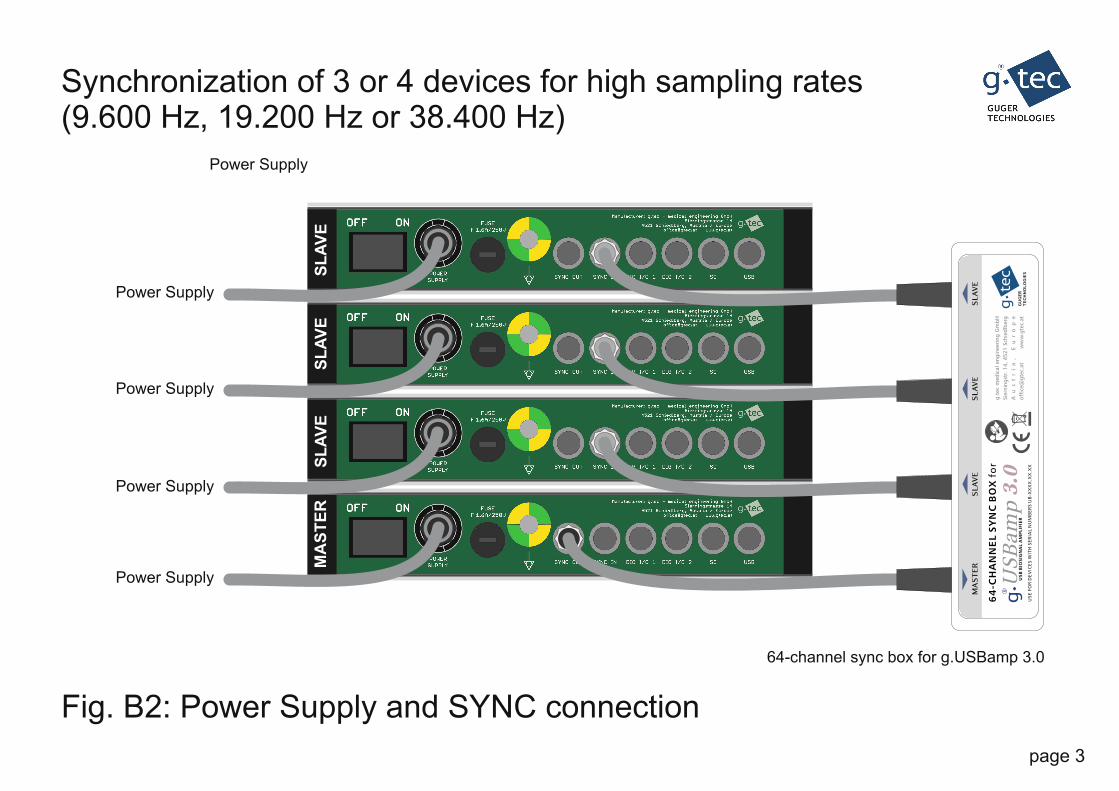
Synchronization of 3 or 4 devices for high sampling rates(9.600 Hz, 19.200 Hz or 38.400 Hz)
Fig. B2: Power Supply and SYNC connection
MA
ST
ER
SL
AV
ES
LA
VE
SL
AV
E
Power Supply
page 3
MA
ST
ER
SLA
VE
SLA
VE
SLA
VE
US
Ba
mp
3.0
US
B B
IOS
IGN
AL A
MP
LIF
IER
64
-CH
AN
NE
L S
YN
C B
OX
fo
r
GU
GE
R
TE
CH
NO
LO
GIE
S
R
g.t
ec
med
ical
en
gin
eeri
ng
Gm
bH
Sie
rnin
gst
r. 1
4,
45
21
Sch
ied
lberg
Au
st
ri
a,
E
ur
op
e
off
ice@
gte
c.at
w
ww
.gte
c.at
US
E F
OR D
EV
ICE
S W
ITH
SE
RIA
L N
UM
BE
RS U
B-X
XX
X.X
X.X
X
64-channel sync box for g.USBamp 3.0
Power Supply
Power Supply
Power Supply
Power Supply
MA
ST
ER
SL
AV
ES
LA
VE
SL
AV
E
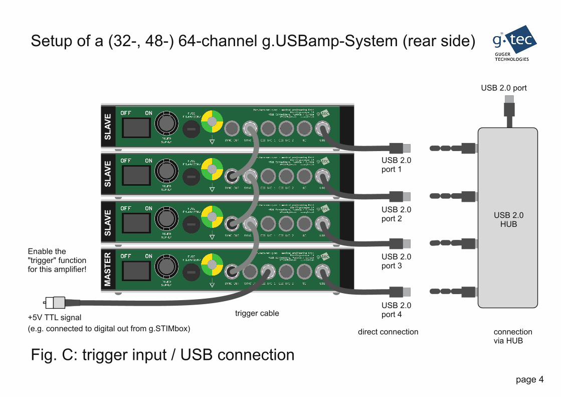
Setup of a (32-, 48-) 64-channel g.USBamp-System (rear side)
Fig. C: USB connection trigger input /
USB 2.0port 1
USB 2.0port 2
USB 2.0port 3
USB 2.0port 4
USB 2.0 port
USB 2.0HUB
direct connection connectionvia HUB
trigger cable+5V TTL signal
(e.g. connected to digital out from g.STIMbox)
Enable the"trigger" functionfor this amplifier!
page 4

Unipolar EEG recording with g.USBamp
block A block B block C block D
GND (connect to block D for impedance check !)
REF
Ch 1 (unipolar, monopolar derivation C3)
Ch 2 (unipolar, monopolar derivation C4)
Ch 3 (unipolar, monopolar derivation Pz)
Ch 4 (unipolar, monopolar derivation Oz)
USE THIS GND FOR IMPEDANCE CHECK !
page 5
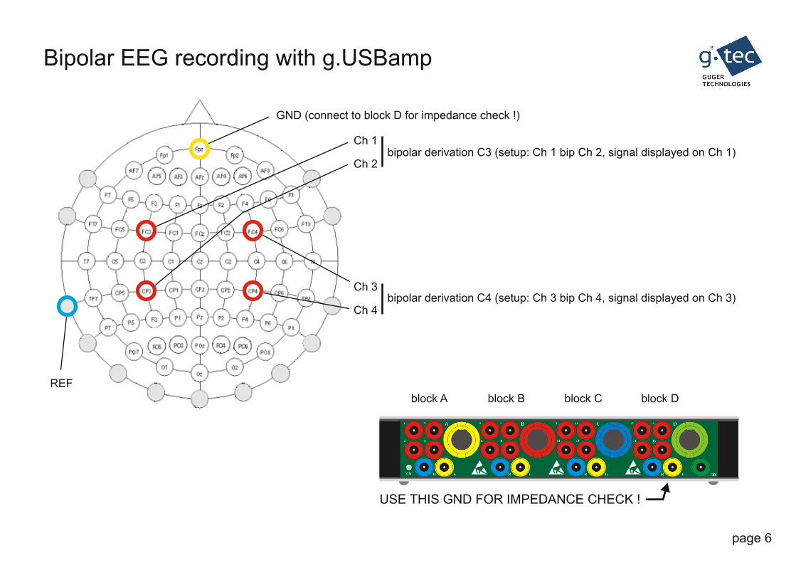
Bipolar EEG recording with g.USBamp
block A block B block C block D
GND (connect to block D for impedance check !)
REF
Ch 1
Ch 2
Ch 3
Ch 4
bipolar derivation C3 (setup: Ch 1 bip Ch 2, signal displayed on Ch 1)
bipolar derivation C4 (setup: Ch 3 bip Ch 4, signal displayed on Ch 3)
USE THIS GND FOR IMPEDANCE CHECK !
page 6

Bipolar ECG/EMG recording with g.USBamp
block A block B block C block D
bipolar EMG derivation (setup: Ch 3 bip Ch 4, signal displayed on Ch 3)
Ch 2
Ch 1
Ch 3Ch 4
REF
GND (connect to block D for impedance check !)
bipolar ECG derivation (setup: Ch 1 bip Ch 2, signal displayed on Ch 1)Ch 1
Ch 2
Ch 3
Ch 4
USE THIS GND FOR IMPEDANCE CHECK !
page 7
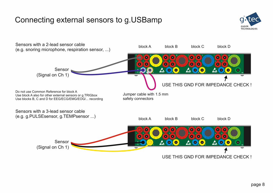
Connecting external sensors to g.USBamp
block A block B block C block D
USE THIS GND FOR IMPEDANCE CHECK !
block A block B block C block D
Sensors with a 2-lead sensor cable(e.g. snoring microphone, respiration sensor, ...)
USE THIS GND FOR IMPEDANCE CHECK !
Jumper cable with 1.5 mmsafety connectors
Sensor
Do not use Common Reference for block AUse block A also for other external sensors or g.TRIGboxUse blocks B, C and D for EEG/ECG/EMG/EOG/... recording
Sensors with a 3-lead sensor cable(e.g. g.PULSEsensor, g.TEMPsensor ...)
Sensor
(Signal on Ch 1)
(Signal on Ch 1)
page 8

page 9
Anti-Static Kit
Avoid or reduce artifacts in biosignal recordings resulting from electro-static chargesin a sub-optimal lab environment and protect sensible electronics.
Subject/Patient Operator
Earth Bonding Point
Wrist BandWrist Band
Earthing Cord
Earthing Cord
Others(if present)