Basics of Photoelasticity - ilis.de · Polarimeter –Sénarmont Measuring Principle •When viewed...
20
1 ilis gmbh | Henkestr. 91 | 91052 Erlangen | Germany | +49 (9131) 9747790 | [email protected] | www.ilis.de Basics of Photoelasticity Henning Katte ilis gmbh, Erlangen
Transcript of Basics of Photoelasticity - ilis.de · Polarimeter –Sénarmont Measuring Principle •When viewed...
1
ilis gmbh | Henkestr. 91 | 91052 Erlangen | Germany | +49 (9131) 9747790 | [email protected] | www.ilis.de
Basics of PhotoelasticityHenning Katte
ilis gmbh, Erlangen

2
© ilis gmbh, all rights reserved www.ilis.de
2
Refractive index?
Optical isotropic?
Birefringence?Polarized light?
Optical retardation?
Temper number?
Polarization angle?
Polarimeter?Polariscope?
Quarter-wave plate?
3
© ilis gmbh, all rights reserved www.ilis.de
3
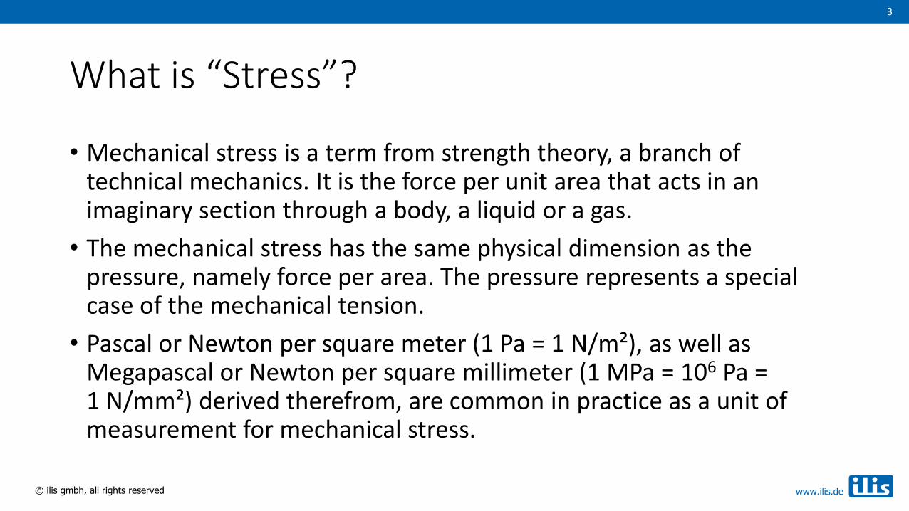
What is “Stress”?
• Mechanical stress is a term from strength theory, a branch of technical mechanics. It is the force per unit area that acts in an imaginary section through a body, a liquid or a gas.
• The mechanical stress has the same physical dimension as the pressure, namely force per area. The pressure represents a special case of the mechanical tension.
• Pascal or Newton per square meter (1 Pa = 1 N/m²), as well as Megapascal or Newton per square millimeter (1 MPa = 106 Pa =1 N/mm²) derived therefrom, are common in practice as a unit of measurement for mechanical stress.

4
© ilis gmbh, all rights reserved www.ilis.de
4
Light and Refractive Index
• Light is an electromagnetic wave that causes atomic shells to vibrate, which in turn generates light.
• The velocity of light in the material depends on the particle density.
• The refractive index is the ratio of the light velocities in the vacuum and in the material: n = c/v
• Ordinary glass: n ≈ 1.5
wavelength
zero-crossing

5
© ilis gmbh, all rights reserved www.ilis.de
5
Stress Birefringence
• Mechanical stress leads to deformation of the material structure and therefore changes the particle density and the velocity of light.
• If the velocity of light (and therefore the refractive index) varies in different directions the material is called birefringent.
• Glass normally is optically isotropic but becomes birefringent when put under mechanical load stress birefringence

6
© ilis gmbh, all rights reserved www.ilis.de
6
Linear Polarization of Light
• If the electric field of light oscillates only in one plane, this is called linearly polarized light.
• A (linear) polarizer lets pass only those light waves which are oriented parallel to its optical axis, thus producing linearly polarized light.

7
© ilis gmbh, all rights reserved www.ilis.de
7
Circular and Elliptical Polarization
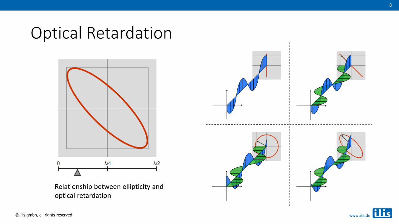
• In a birefringent material, the light waves propagate in horizontal and vertical directions at different speeds, resulting in an optical path difference or optical retardation.
• Linearly polarized light leaves a birefringent material as a superposition of two mutually perpendicular light waves of different phasing.
• If the optical retardation is exactly one quarter of the wavelength, the light is circularly polarized.
• In the general case, the emergent light is elliptically polarized.
• The ellipticity is a measure of stress birefringence.
8
© ilis gmbh, all rights reserved www.ilis.de
8
Optical Retardation
Relationship between ellipticity and optical retardation
9
© ilis gmbh, all rights reserved www.ilis.de
9
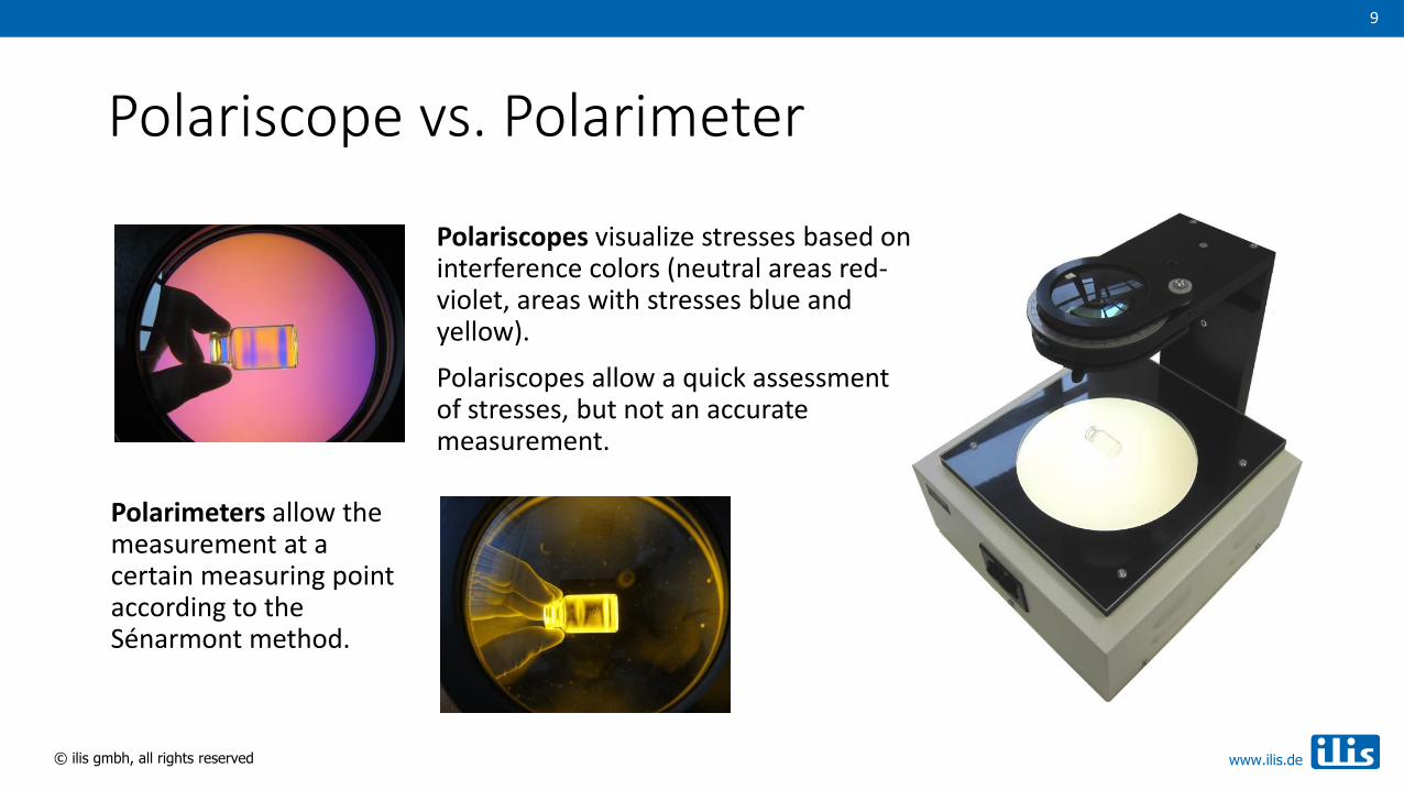
Polariscope vs. Polarimeter
Polariscopes visualize stresses based on interference colors (neutral areas red-violet, areas with stresses blue and yellow).
Polariscopes allow a quick assessment of stresses, but not an accurate measurement.
Polarimeters allow the measurement at a certain measuring point according to the Sénarmont method.

10
© ilis gmbh, all rights reserved www.ilis.de
10
Polariscope – Structure and Working Principle
Full wave plate
Light source
Polarizer
Specimen
Polarizer (crossed)
Detector• Polariscopes with two crossed polarizers
show colored images with birefringent materials and a white light source.
• Stress birefringence generates elliptically polarized light that partially passes the second polarizer. The degree of extinction depends on both birefringence and wavelength.
• If a color is filtered out of the spectrum, the remaining light assumes the complementary color. This interference color can be translated into retardations using color scales.
0 200 400 600 800 1000 1200 1400 1600 1800 nm

11
© ilis gmbh, all rights reserved www.ilis.de
11
Full Wave Plate (1st Order Red Tint Plate)
• At low retardations (<300 nm), the image is not colored; different delays cause different gray levels.
• By adding a full wave plate, the retardation can be shifted to a region that is more easily evaluated, e.g. around 550 nm.
• Negative retardation then appear in yellow and positive values in blue. Neutral areas are red-purple.
0 200 400 600 800 1000 1200 1400 1600 1800 nm
12
© ilis gmbh, all rights reserved www.ilis.de
12
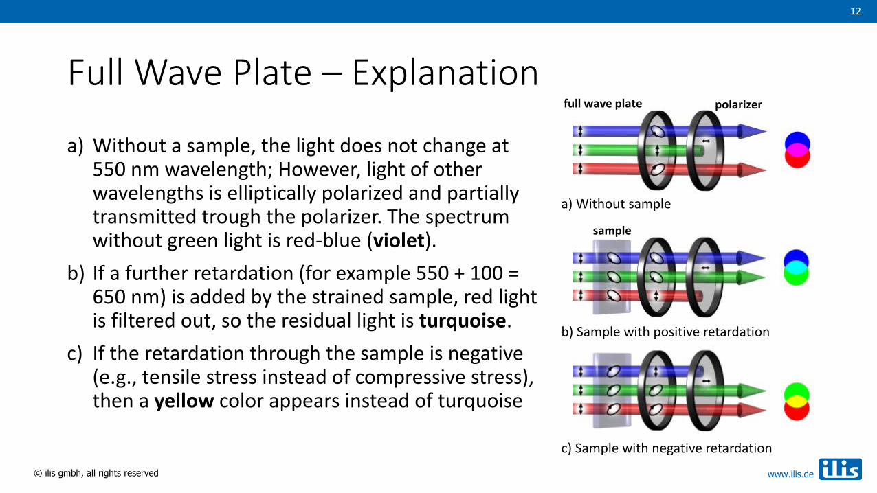
Full Wave Plate – Explanation
a) Without a sample, the light does not change at 550 nm wavelength; However, light of other wavelengths is elliptically polarized and partially transmitted trough the polarizer. The spectrum without green light is red-blue (violet).
b) If a further retardation (for example 550 + 100 = 650 nm) is added by the strained sample, red light is filtered out, so the residual light is turquoise.
c) If the retardation through the sample is negative (e.g., tensile stress instead of compressive stress), then a yellow color appears instead of turquoise
a) Without sample
b) Sample with positive retardation
c) Sample with negative retardation
polarizer
sample
full wave plate

13
© ilis gmbh, all rights reserved www.ilis.de
13
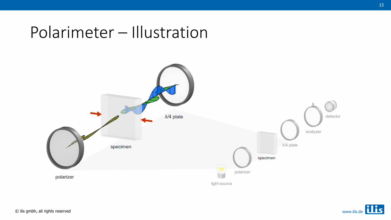
Polarimeter – Structure and Working Principle
• The polarimeter structure is very similar to the polariscope design, but instead of a full wave plate, a quarter wave plate is used and the second polarizer (analyzer) is rotatable.
• A quarter-wave plate consists of birefringent material and produces a path difference of one quarter of the wavelength (hence /4 plate).
• Linearly polarized light, which incidents at an angle of 45° to the optical axes, is converted into circularly polarized light.
• Conversely, elliptically polarized light is converted back into linearly polarized light by the /4 plate, but with a different polarization angle.
Quarter wave plate (retarder)
Light source
Polarizer
Specimen
Analyzer (rotatable)
Detector

14
© ilis gmbh, all rights reserved www.ilis.de
14
Polarimeter – Sénarmont Measuring Principle
• When viewed through a polarizer crossed to the original polarization direction, strained parts of the sample appear as brightened areas in the otherwise black field of view.
• The polarization angle describes the ellipticityof the light emerging from the sample, and is therefore a measure of the birefringence and thus of the stress in the material.
• The polarization angle is measured by turning the analyzer until the brightened area is darkest.
15
© ilis gmbh, all rights reserved www.ilis.de
15
Polarimeter – Illustration

16
© ilis gmbh, all rights reserved www.ilis.de
16
Common Measurements Units
• From the polarization angle , the optical retardation R in nm can be calculated according to the following formula:
R = · / 180° ( = used wavelength in nm)
• If the birefringence along the measuring beam is homogeneous, the normalized optical retardation N in nm/cm can be calculated:
N = R · (10 / d) (d = sample thickness in mm)
• In the case of membrane stresses (and only then), the optical retardation can be converted to stress S in MPa as long as the photoelastic coefficient (a material constant) is known:
S = R / (d · C) (C = photoelastic coefficient in TPa-1)
17
© ilis gmbh, all rights reserved www.ilis.de
17
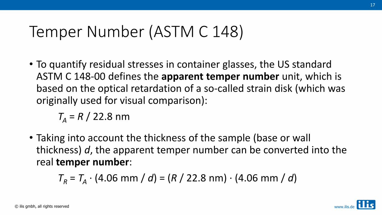
Temper Number (ASTM C 148)
• To quantify residual stresses in container glasses, the US standard ASTM C 148-00 defines the apparent temper number unit, which is based on the optical retardation of a so-called strain disk (which was originally used for visual comparison):
TA = R / 22.8 nm
• Taking into account the thickness of the sample (base or wall thickness) d, the apparent temper number can be converted into the real temper number:
TR = TA · (4.06 mm / d) = (R / 22.8 nm) · (4.06 mm / d)
18
© ilis gmbh, all rights reserved www.ilis.de
18
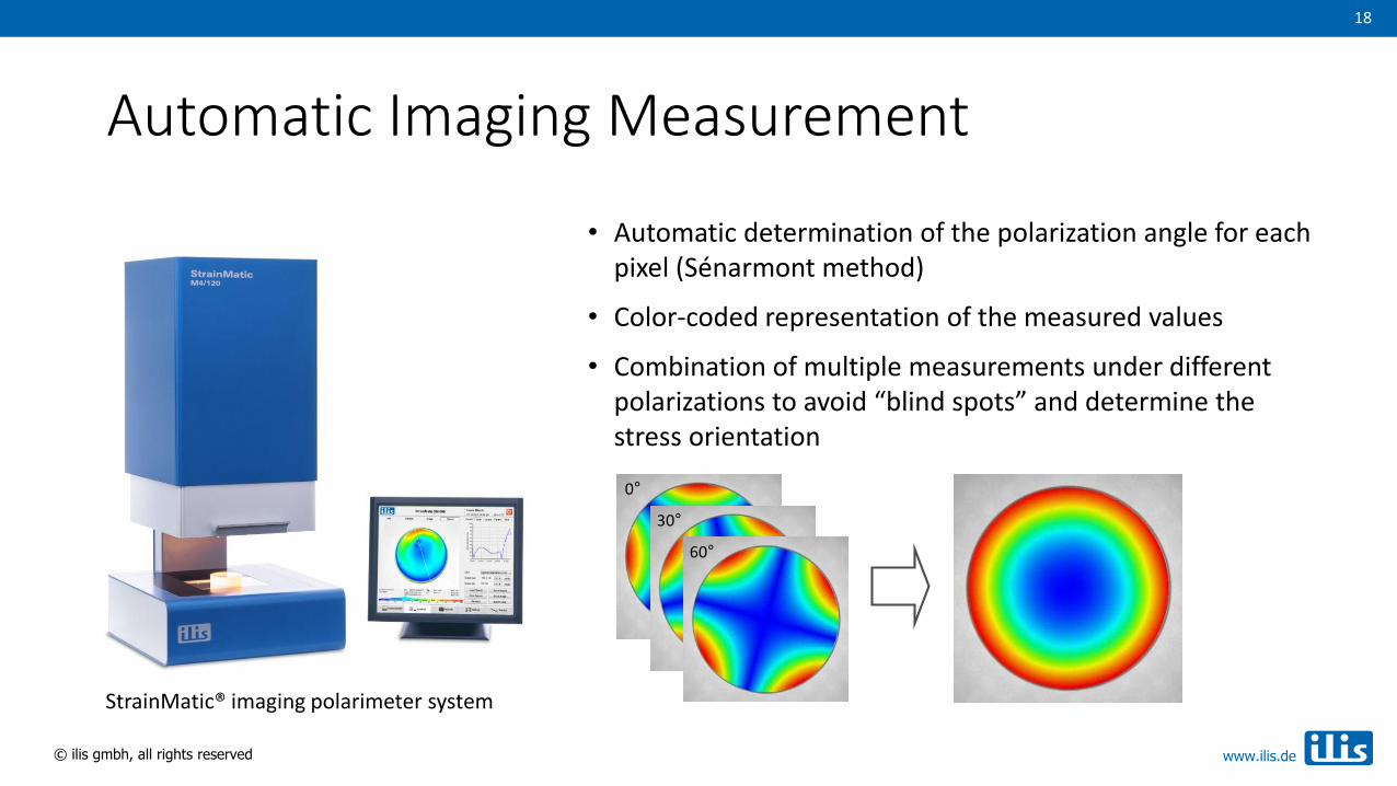
Automatic Imaging Measurement
• Automatic determination of the polarization angle for each pixel (Sénarmont method)
• Color-coded representation of the measured values
• Combination of multiple measurements under different polarizations to avoid “blind spots” and determine the stress orientation
StrainMatic® imaging polarimeter system
0°
30°
60°

19
© ilis gmbh, all rights reserved www.ilis.de
19
Continuous Measurement in Real Time
• Rotatable analyzer replaced by a special polarization camera with no moving elements
• Measurement in real time (20 Hz), also on moving objects and directly in the process
• Measurement with circularly polarized light allows determinationof correct magnitude and orientation of the stresses
StrainScope® real time polarimeterlinearly polarized circularly polarized
20
© ilis gmbh, all rights reserved www.ilis.de
20
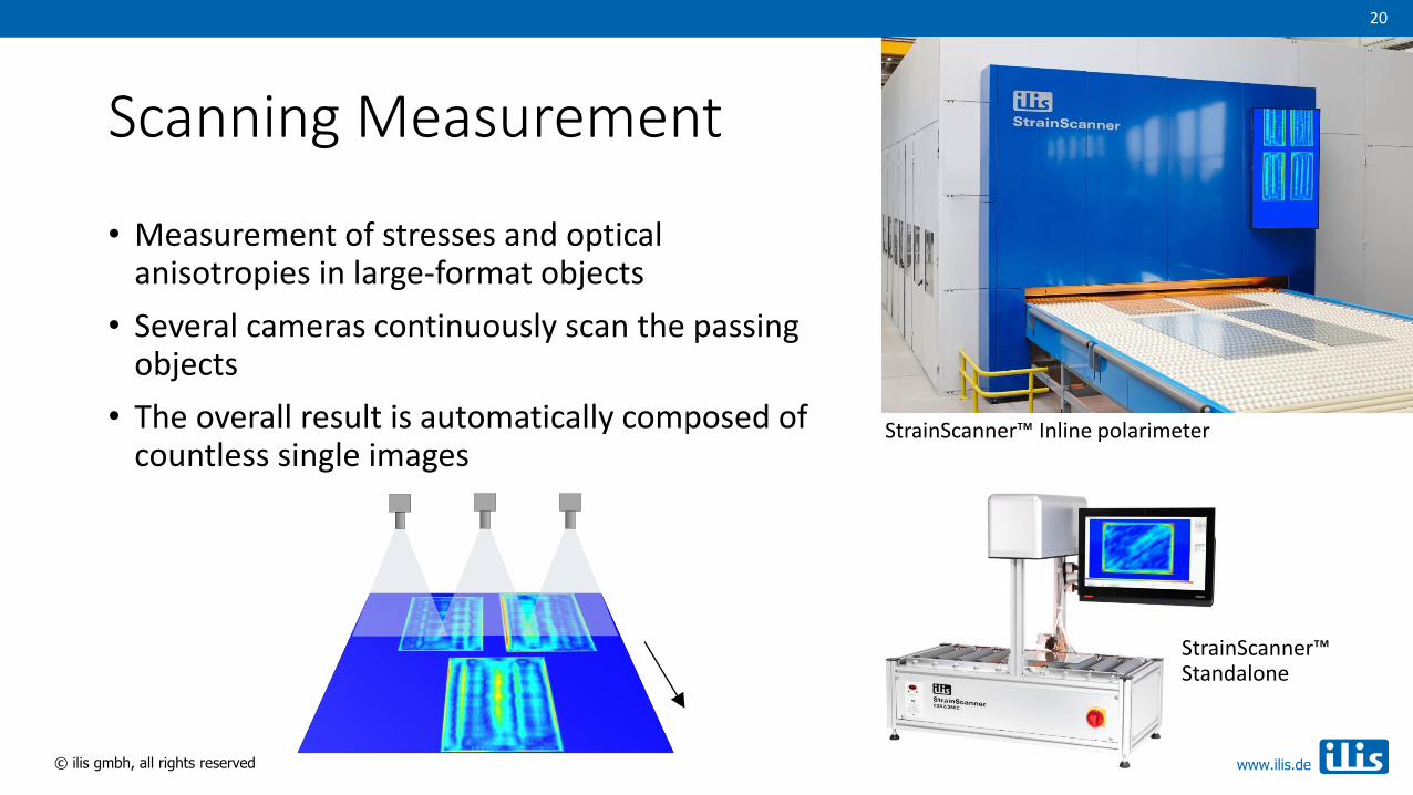
Scanning Measurement
StrainScanner™ Inline polarimeter
StrainScanner™ Standalone
• Measurement of stresses and optical anisotropies in large-format objects
• Several cameras continuously scan the passing objects
• The overall result is automatically composed of countless single images