© Fluent Inc. 9/8/20151 Fluent Software Training TRN-98-006 Welcome to Fluent Inc.

Basics of CFD and Operations in Fluent

Basic concepts of Numerical Calculations
Pre-processing in Fluent
Solutions
Post processing in Fluent
Programming: Journaling, Scripting, UDF

Analytical vs. Numerical Approach

Analytical Calculation vs. Numerical Calculation
• Analytical Results
• Available as explicit or implicit form of an equation such as a quadratic equation.
• It is a continuous equation, available at each point is space (Infinite Unknowns)
• Numerical Calculation
• Available at discrete location in space / time dimensions (Finite Unknowns)
• It is an inherently discontinuous approach with some averaging / blending to ensure
physical correctness
• Examples
• Simply supported beam - Analytical
• Plate temperature distribution - Numerical
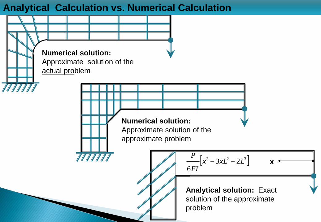
Numerical solution:
Approximate solution of the
actual problem
Numerical solution:
Approximate solution of the
approximate problem
Analytical solution: Exact
solution of the approximate
problem
Analytical Calculation vs. Numerical Calculation
x 323 236
LxLxEI
P

Traditional Design Methodology
Product
Requirement
Physical Prototypes
Physical Testing
Design Changes
• Long Product Development Cycle
• Many prototypes
• Very Costly
Modern Design Methodology
Product
Requirement
Virtual Prototypes
Virtual Testing
Design Changes
• Minimal Prototypes and Cost Effective
• Product Development Cycle Drastically Reduced
• Better Insight into various Design Aspects
Physical Prototype
Physical Testing
CAX:
CAD, CAE,
CFD, CAA
Traditional vs Virtual Design Evaluations

Pre-processing
Solver Setting &
Solution
Post-processing
Define Input / Output - Assumptions based on Engg. Judgment
Prepare CAD Model, De-featuring & Simplification for CFD meshing
Generate Mesh and Define Zones / Patches – inlet, outlet, wall, symmetry …
Define Thermodynamic and Transport Properties of Material
Specify Boundary and Initial Condition
Select flow model: Laminar, Turbulent, Single-phase, Multi-phase …
Select appropriate turbulence model based on flow type, wall function
Specify discretization schemes, time steps …
Analysis Run: Batch Mode (command line), GUI, Remote Server
Contour Plots, Velocity Vectors, Streamlines, Pathlines, Isolines …
Animations for Streamlines, Particle Tracks, Coefficients of Pressure …
Report Preparation
Typical Flow Chart for Numerical Analysis

Local Server: GUI-operations and their meaning

Starting Fluent
1. 2D or 3D, single precision or double precision (dp -> double precision)
2. Pre-processing, Solution and Post Process [Full Simulation] or just post-processing
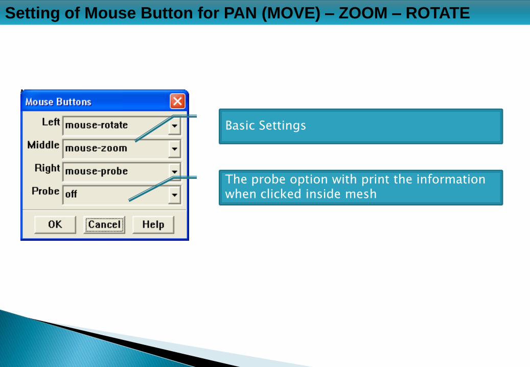
Setting of Mouse Button for PAN (MOVE) – ZOOM – ROTATE
Basic Settings
The probe option with print the information when clicked inside mesh

Reading Mesh: File Import Mesh, Read Case …
Select as appropriate
File GUI Menu

Reading Mesh: File Import Mesh, Read Case …
Top panel describes the summary of case file
Software operation summary. Note ‘done’ at the end! Any error will be reported here.
GUI Menu
TUI Menu

Check Mesh: Grid Check
Check at the bottom for error message

Check Mesh: Repair Shadow Zones in Periodic Mesh
TUI: grid modify-zones repair-periodic
1. The program will automatically try to detect the periodic distance or angles though will ask to user inputs as well
2. The command can be shortened as: grid mz rp
WARNING: node on face thread 2 has multiple shadows. This warning message appears only in case of periodic (translational of rotational) faces! These faces can be repaired only through the Text User Terminal (TUI)

Manipulate Mesh: Optional for ease of simulation
1. Merging Zones: combining multiple zones of similar type – process not fully
reversible (de-merging to previous state not possible): keep back-ups
2. Separating Zones: Opposite of “Merging Zones” – required if say there are
multiple outlets and all grouped into single zone in the meshing software.
3. Creating Periodic Zones, Slitting Periodic Zones: For periodic zones
4. Scaling the Grid – FLUENT is a metric solver. Scale the mesh appropriately to
convert into meters. E.g. if mesh was generated in inch, scale factor = 0.0254
5. Translating the Grid: Move the grid in required to move near origin
6. Rotating the Grid: Rotate the mesh to orient to particular axis

Manipulate Mesh: Optional for ease of simulation
Some other options for the sake of completeness
1. Fusing Face Zones: fuse boundaries (and merge duplicate nodes and faces)
created by assembling multiple mesh regions.
2. Slitting Face Zones: Not same as separating a face zone! Slit an internal wall or
coupled wall zone into two distinct uncoupled zones.
3. Extruding Face Zones: A face can be extruded to increase the domain size say
changing location of the outlet to prevent reverse flow.
4. Replacing, Deleting, Deactivating, and Activating Zones
5. Reordering the Domain and Zones

Manipulate Mesh: Separate Face Zones
This feature is most used among all the options described earlier
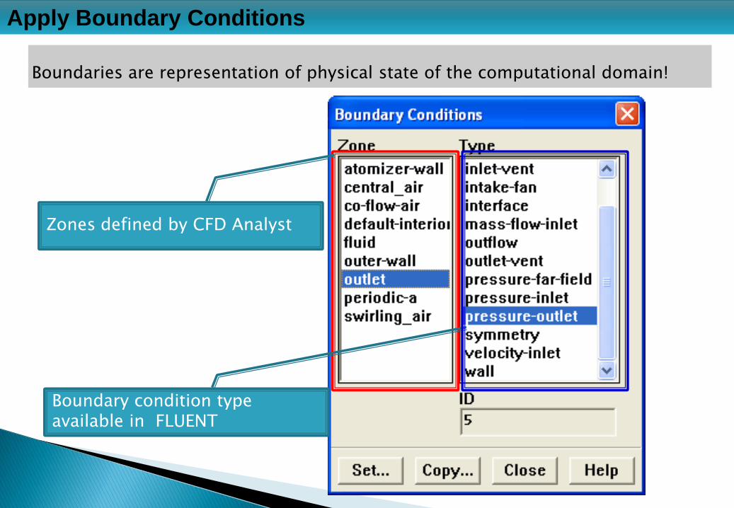
Apply Boundary Conditions
Boundaries are representation of physical state of the computational domain!
Zones defined by CFD Analyst
Boundary condition type available in FLUENT

Define Material Properties
Thermodynamic and transport properties of all the phases
Thermodynamics properties
Transport properties
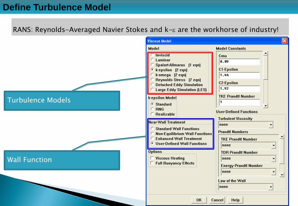
Define Turbulence Model
RANS: Reynolds-Averaged Navier Stokes and k-e are the workhorse of industry!
Turbulence Models
Wall Function

Solver running, monitor and convergence parammeters
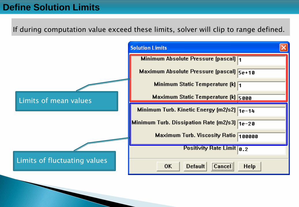
Define Solution Limits
If during computation value exceed these limits, solver will clip to range defined.
Limits of mean values
Limits of fluctuating values

Define Initial Values: solve Initialize Initialize …
A better guess helps improve the convergence sometimes!
Based on selected boundary
Calculated value

Define Convergence Criteria: Solve Monitors Residual …
When the solver should stop running? Either criterion-1 or criterion-2 is met!
Print in the console and plot as graphical chart
Criterion-2
Criterion-1

Qualitative plots, quantitative integration and averaging

Display Contour Plots: Display Contours …
Contour: coloured representation of field variables on a plane or surface
How to show the plot and interpolate the results?
Number of sub-divisions in legend
Criterion-1
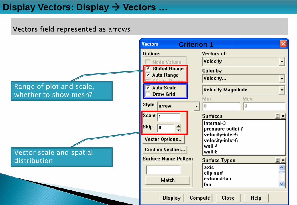
Display Vectors: Display Vectors …
Vectors field represented as arrows
Range of plot and scale, whether to show mesh?
Vector scale and spatial distribution
Criterion-1
Volumetric heat source, temperature dependent material properties …

UDF: User-Defined Function, Journals and Transcripts
1. FLUENT uses programming languages SCHEME (TUI), FORTRAN (back-end
mathematics) and Tcl/Tk (GUI)
2. UDF: FLUENT is a general-purpose CFD simulation program and cannot
address all the physical variations. UDF fills this gap.
3. Journals and Transcripts are similar recording of VBA scripts in EXCEL.
4. The details of this feature is covered under advance topic once you get
mastery of the topics covered so far!

Please visit http://www.cfdyna.com for explore more about CFD and related stuff.
You may write to me at [email protected] to get help on any advance topic!