BASIC PRINCIPLES FOR DESIGN AND CONSTRUCTION OF PHOTOVOLTAIC PLANTS Ing. Salvatore Castello ENEA -...
35
BASIC PRINCIPLES FOR DESIGN AND CONSTRUCTION OF PHOTOVOLTAIC PLANTS Ing. Salvatore Castello ENEA - Renewable Energy Technical Unit - Photovoltaic Lab TRAINING COURSE TRAINING COURSE
-
Upload
dwight-price -
Category
Documents
-
view
227 -
download
1
Transcript of BASIC PRINCIPLES FOR DESIGN AND CONSTRUCTION OF PHOTOVOLTAIC PLANTS Ing. Salvatore Castello ENEA -...

BASIC PRINCIPLES FOR DESIGN ANDCONSTRUCTION OF PHOTOVOLTAIC PLANTS
Ing. Salvatore CastelloENEA - Renewable Energy Technical Unit - Photovoltaic Lab
TRAINING COURSE TRAINING COURSE

Summary
• Criteria for selecting PV modules• Strings and PV generator• Supporting structures• Fire prevention • Power conditioning unit• The connection to the grid• Design documentation

THE INVERTER
• Converts the DC to AC
• It must be fit to transfer the power from the PV array to the distributor grid, in compliance with regulatory requirements, technical and safety standards.
• Features:• PWM technique• able to operate in automatic mode (on, off)• able of tracking the maximum power point (MPPT) of the PV generator
• typologies:• LINE-Commutated: for grid-connected systems• SELF-Commutaded: for stand alone or grid-connected systems
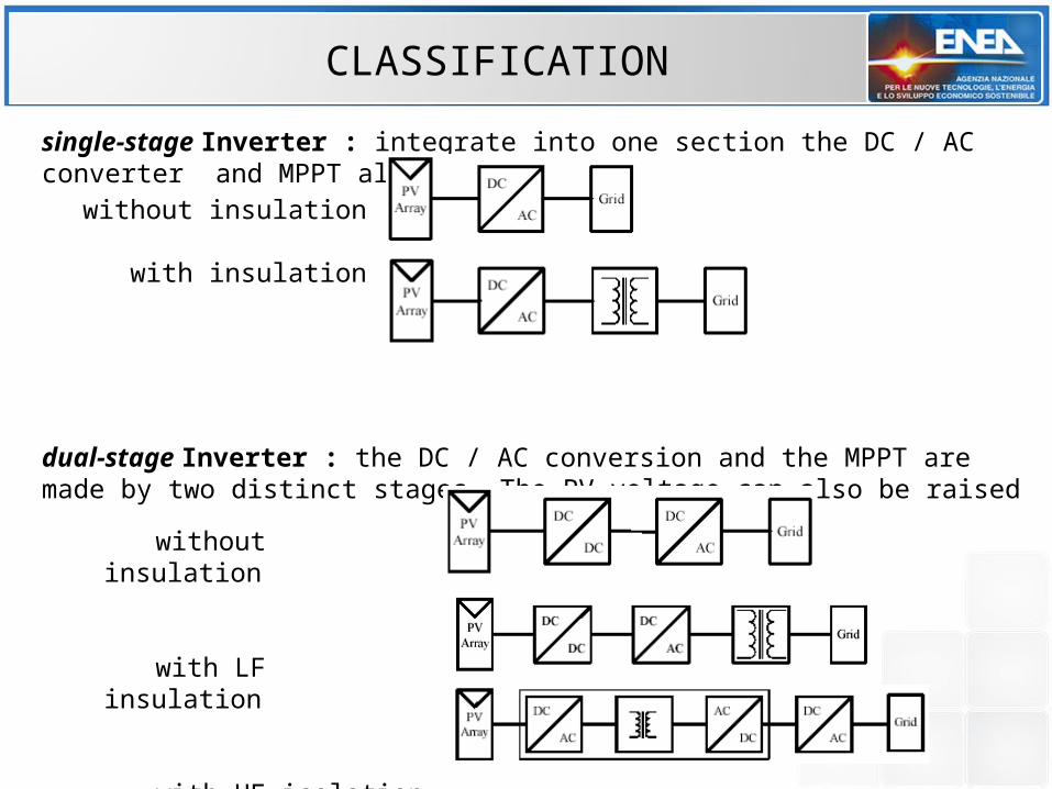
CLASSIFICATION
single-stage Inverter : integrate into one section the DC / AC converter and MPPT algorithm
dual-stage Inverter : the DC / AC conversion and the MPPT are made by two distinct stages. The PV voltage can also be raised
without insulation
with insulation
without insulation
with LF insulation
with HF isolation

DC/DC CONVERTER
• Converts the DC voltage at its input according to a variable conversion ratio : Vo = k Vi
• Formed by: chopper / HF trafo (optional) / rectifier
• Typical functions• Voltage regulator in systems with storage• Control and voltage regulation (grid connected)• Maximize the energy produced by the photovoltaic generator
(MPPT)
• Efficiency: 98-99% in a broad range of input power
• Basic circuits:• BUCK Vo < Vi• BOOST Vo > Vi• FLAYBACK Vo < > Vi

MAXIMUM POWER POINT TRACKING
Indirect method: try and testif P >0 then V’=V+V else V’=V-V
Multi Operating modes • Indirect (try and test)• Direct
• measurement of Irr and T• V scannering
P
V
Pm
VP
Starting point
MPPT point
Relative maximum

DC/AC INVERTER BASIC CIRCUITS
LOAD
LOAD
PUSH - PULL
BRIDGE
DC/AC BRIDGE
ConfigurationsPUSH-PULL BRIDGE
PWM MODULATION
The Output frequency and phase are generated electronically by controlling the width of voltage pulses
These techniques require switching power devices (transistors or IGBTs) in order to generate a proper voltage level

INVERTER SINGLE-STAGE WITH LF TRANSFORMER
advantages:- ability to manage the photovoltaic generator with one pole-to-ground limitations:- lower efficiency than systems transformerless;- high weight, dimensions and noise
Varistors DC filter DC/AC Bridge AC filter Trafo interface device EMC filter Var
Controller

INVERTER SINGLE-STAGE WITHOUT TRANSFORMER
advantages:- high efficiency - circuit simplicity- low weight and dimensionsdrawbacks:- photovoltaic generator necessarily "floating" (NO 1-pole to ground capability);- limited range of input voltage
Varistors DC filter DC/AC Bridge AC filter interface device dc protect. EMC filter

INVERTER DUAL-STAGE WITH HF TRAFO
advantages:- galvanic insulation- 1-pole to ground possibility- weight and overall dimensions smaller than with LF transformer- extended imput voltage range (dc / dc converter)limitations:- lower efficiency of transformerless (2 stages);
Varistors DC/DC isolated dc filter DC/AC Bridge AC filter interface device EMC filter
HF trafo
controller

THE INVERTER
• three-phase connection can be obtained using• three-phase inverter
• 3 single-phase inverters connected between one phase and neutral (maximum unbalance allowed is fixed by the Utility)
• The values of the output voltage and frequency must be consistent with those of the grid at which it is connected

INVERTER – ARRAY COUPLING
Vpv,min Voc @Tmin
Low voltage field (not sufficient
to startup)
Vpv,max
Vmin
Safety operation fieldpossibledamage
field
overvoltage protection
mode
Vmax
PV Generator
InverterInput
voltage
V0
startup threshold
(depending on grid voltage)
The voltage of the PV array must be compatible with the input voltage range of the inverter (Vmi, Vmax)

INVERTER
• The inverter is sized taking into account the rated power of the PV field (typically Pnom_inv = 0.85 * Pnom_pv)
• Typically equipped with • Grid interface protection device• device to check the insulation of the PV field• transformer to ensure the metal separation (LF or HF)
• In case of absence of the transformer (TL), the metal separation can be replaced by a DC overcurrent protection device
(which acts when the level of DC componed fed into the grid > allowed threshold)

INVERTER
• may be suited for indoor or outdoor installations, depending on the degree of protection
• is characterized by a range of ambient temperatures. Beyond which the inverter can limit the power output or shutdown
• electromagnetic interferences should remain within prescribed values. Are generated by switching devices and are• induced in the cables• air radiated
• To minimize the interferences is appropriate to comply manufacturer instructions• Grounding• Do not installed in proximity to sensitive equipment

INVERTER EFFICIENCY
Losses:• constant = power absorbed by the control circuitry + magnetic losses• proportional to Pi = switching losses• proportional to Pi2 = losses due to joule effect (inductors and transformer)
EU efficiency (weighted average over operation time at specific levels of Pi)
eur = 0,035% + 0,06 10% + 0,1320% + 0,130% + 0,4850% + 0,2100%

INVERTER EFFICIENCY
Typical average values of effiency: - 94-97% TL - 92-96% LF transformer - 92-94% HF transformer- 98,5% devices based on silicon carbide

INVERTER FEATURES• General
• Efficiency• ambient temperature range• Insulation level between the DC and AC• Protections for internal faults• Noise Level• EM emissions• Compliance standards for grid connection• Monitoring capability
• Input• Voltage range• Pnon, Pmax, Imax, Vmax, Pmin• # MPPT• Protections (over-voltage, inversion, array insulation)
• Output• Voltage, frequency and number of phases• Voltage and frequency ranges• Pnon and Pmax, Imax• Harmonic distortion total and single, power factor• Protections (islanding, over voltage and over-current)

INVERTER TIPOLOGIES
CENTRALIZED INV. STRING INVERTER MULTISTRING INV. MODULE INV.

CENTRALIZED LAYOUT
AuroraAuroraPVI-CENTRALPVI-CENTRAL
Example: Fonte Power One
PROS• Conten cost per unit • Speed and ease of installation (cabins
provided in turnkey solution)• connection directly in MV grid• Highest levels of efficiency - up to
98.6% (inverter)
DRAWBACKS• Low continuity of exercise (for inverter
fault);• Complex wiring of DC side
(switchboard and protections required)
• Reduced efficiency of the PV generator due to mismatch
• Constrained exposure and string configuration

CENTRALIZED SYSTEM ARCHITECTURE
Source: Elettronica Santerno

CENTRALIZED PLANT LAYOUT
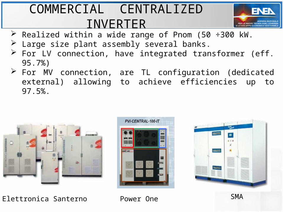
Realized within a wide range of Pnom (50 ÷300 kW. Large size plant assembly several banks. For LV connection, have integrated transformer (eff. 95.7%) For MV connection, are TL configuration (dedicated external) allowing to
achieve efficiencies up to 97.5%.
COMMERCIAL CENTRALIZED INVERTER
Elettronica Santerno Power One SMA

MODULAR CENTRALIZED INVERTER
The inverter consists of several modules (ranging from 30 to 300 kW) the number of modules in operation depends on array output power
(irradiation) In the event of a module failure the remaining modules configurate
their contribution performing also the function of the fault module
commercial solutions:
FRONIUS MIX™Power One

DISTRIBUTED LAYOUT
Source: Power OneADVANTAGES• Good flexibility
• Shadowing management• Strings differently oriented• “Mixed“ module technologies
• Simplified installation • Standard design
• High plant availability• In case of failure quick
replacement executable by unqualified personne
DRAWBACKS• Higher unit cost • AC side wiring more complex

• String Inverters: Each string has its own dedicated inverter• Multi-input inverter: DC side act like a string inverters, while the AC side
works as a central inverter.• Module inverter (microinverter): devices of small power (a few hundred
W), suitable for direct AC connection of modules• High unit cost• Technical rules still lacking for safety aspects
INVERTER FOR DISTRIBUTED LAYOUT

LAYOUT OF DISTRIBUTED SYSTEM
In economic terms, there are not definite advantages in favor of one or the other solution
In real operating conditions should be taken into account inverter faults and the consequent reduction of energy production This factor lean toward distributed solutions
However, with the modular technology applied to large size inverter is possible to balance pro and cons of centralized and distributed generation, ensuring an effective reduction of energy losses associated with the single
failure in centralized configurations
CENTRALIZED VS. DISTRIBUTED

Module DC/DC Buck converter:Raises the current of the shaded module to align it to that of the string (reducing the voltage, compatible with the power that can deliver the module)
THE OPTIMIZER

TL INVERTERS WITH ONE POLE TO GROUND
Typologies born to exploit the benefits of -higher efficiency of TL inverters and-allow the management of a PV array with one pole to ground
It is said that the inverter can operate in dual ground configuration (both in AC and DC side), even in absence of transformer
The grounding of one pole of the array is necessary in some technologies-thin-film modules; to prevent premature degradation-back contact modules: reduce efficiency- metal substrate thin-film: limit leakage currents

TL INVERTERS WITH ONE POLE TO GROUND
Are based on the principle of disconnecting the DC from the AC side of the inverter during the period of freeweeling, (when the grid could be put in short-circuit through the array pole to ground)
high efficiencies (up to 97 - 98%) ground connection is made using special kits For safety reasons, is continuously monitored the level of insulation of the PV
array

POLARIZZATION OF C-SI BACK CONTACT MODULES
If the cell contact are located on the same side, the electric field is not uniform
a static charge occurs on the surface of cells that cause a reduction of the efficiency
The effect is reversible, as soon as the charges are removed The removal of the charges is performed grounding the positive pole of the
PV array (during freeweeling period)

TCO CORROSION IN THIN FILM MODULES
Regards a-Si and CdTe modules in superstrate configuration (deposition on the cover glass).
The TCO corrosion is caused by the reaction between moisture (from the edges) and the sodium, present in the glass
The corrosion is proportional to the potential of PV generator poles to ground
with the grounding of the positive pole of the PV generator is generated an electric field that reject the positive ions of sodium from the TCO layer.
In this way it is possible to prevent corrosion

HIGH LEAKAGE CURRENTS
In TL inverter the grid alternate voltage reflect a fluctuation on the DC side The problem arise in metal substrate thin-film modules that have high
parasitic capacitance (large surfaces and small distance between electrodes)
The undulations generate a high leakage current that could shutdown inverter
grounding a pole of the array has a stabilizing action of the fluctuations
.
Inverter

INVERTER SELECTION AND MODULE TECHNOLOGY
Some manufacturers provide tables in order to facilitate the selection of the inverter suitable for the various module technologies
Module technology Compatible inverter
Cristalline silicon (c-Si) All (TL; HF; LF)
All back-contact With transformer (HF; LF)+ positive pole to ground
Thin Film (TF) - superstrate With transformer (HF; LF)+ pnegative pole to ground
CdTe (First Solar) All (subject to verification of FS)
Thin Film (TF) –substrate (Unisolar o affini, senza parti metalliche limitrofe)
All (TL; HF; LF)
Unisolar o similar on metal substrate
With transformer (HF; LF)+ TL in “quiet rail” technology