Basic Operation of a Small Gas Turbinegasturbineworld.co.uk/Small Gas Turbines 1 operation.pdf ·...
77
Chapter 1 Basic Operation of a Small Gas Turbine There has been many books written on the subject of gas turbine theory and it would be beyond the scope of this document to go into it in detail here. References will be given at the end of this document for those who need to pursue the theory further. A basic practical description relating to how a small gas turbine engine works follows. Heat engines all work by utilizing the resulting expansion of a fluid when it has become heated (Normally by the combustion of fuel and air), this fluid is usually found to be air or a gas. If this fluid is compressed before it is heated, then the amount of subsequent expansion will be increased (When the cycle is open to atmosphere). In a piston internal combustion engine, the expansion of gas is restricted as it is placed in the space enclosed by the combustion chamber cylinder and the piston carried by it; This causes the contained pressure to increase and act upon the piston crown thus creating a force upon it. As a result of this force the piston moves and turns a flywheel via a crank. A gas turbine is very similar although the combustion chamber strictly speaking is not enclosed; The expanding heated gas acts upon a turbine wheel that is used to provide power. In a piston engine, the flywheel (Or another piston power stroke) pushes the piston upwards (with energy from a starter or the previous cycle) to compress the ingested air ready for heating and expansion. In a gas turbine, air is compressed using a rotating impeller, which is driven by the turbine.
Transcript of Basic Operation of a Small Gas Turbinegasturbineworld.co.uk/Small Gas Turbines 1 operation.pdf ·...

Chapter 1
Basic Operation of a Small Gas Turbine
There has been many books written on the subject of gas turbine theory and it would be
beyond the scope of this document to go into it in detail here. References will be given at
the end of this document for those who need to pursue the theory further. A basic
practical description relating to how a small gas turbine engine works follows.
Heat engines all work by utilizing the resulting expansion of a fluid when it has become
heated (Normally by the combustion of fuel and air), this fluid is usually found to be air
or a gas. If this fluid is compressed before it is heated, then the amount of subsequent
expansion will be increased (When the cycle is open to atmosphere). In a piston internal
combustion engine, the expansion of gas is restricted as it is placed in the space enclosed
by the combustion chamber cylinder and the piston carried by it; This causes the
contained pressure to increase and act upon the piston crown thus creating a force upon it.
As a result of this force the piston moves and turns a flywheel via a crank. A gas turbine
is very similar although the combustion chamber strictly speaking is not enclosed; The
expanding heated gas acts upon a turbine wheel that is used to provide power. In a piston
engine, the flywheel (Or another piston power stroke) pushes the piston upwards (with
energy from a starter or the previous cycle) to compress the ingested air ready for heating
and expansion. In a gas turbine, air is compressed using a rotating impeller, which is
driven by the turbine.

The pressure in the combustion chamber of a piston engine rapidly increases when the
enclosed fuel/air mixture is ignited and heats up. The pressure developed across the
piston results in the force placed upon the piston crown. In as gas turbine engine
combustion chamber, the combustion process is continuous and takes place at constant
pressure. The combustion causes the gases to expand and flow with increased velocity
out of it and impinge on the turbine to drive the engine and an external load.
A very important application of a gas turbine was first suggested by the engineer and
pilot Sir Frank Whittle. Whittle did not invent (although he did contribute enormous
advances to it) the gas turbine or even jet propulsion but put forward the visionary
concept of putting the two principals together to create the turbo-jet engine (At that time
many others believed the gas turbine could best be used to drive a propeller or air screw).
A running gas turbine is a prime mover that naturally produces a high mass flow of
heated gas (consisting of a mixture of air and combustion products). The exhaust from a
gas turbine engine may be directed through a restricting nozzle to propel the engine
forward. A combination of the momentum increase of the mass of air flowing through the
engine and the pressure developed across the exhaust nozzle creates a reaction upon the
engine; this reaction produces what is known as thrust. This is how a turbo-jet engine
operates; the "load" on the gas turbine is created by the exhaust nozzle, the engine
"pumps" its own exhaust gases through it. All turbo-jet engines are gas turbines, but not
all gas turbines are used in this way and can be considered to be turbo-jet engines.
The principal difference between a piston engine and a gas turbine is that the processes in
a gas turbine are simultaneous and continuous; in a piston engine these processes occur
individually as a number of repeating cycles. If you study the temperatures and pressures
within heat engines, more detail differences between turbines and pistons become
apparent. Aerodynamics also play a key role in gas turbine operation, the flow of gases
through passages, around turbine blades and inside compressors is crucial to their
efficient operation. Throughout a gas turbine engine there are many passage-ways, ducts
and nozzles through which the working gases pass, the cross-sectional areas and profiles
of these components form much of the overall design.
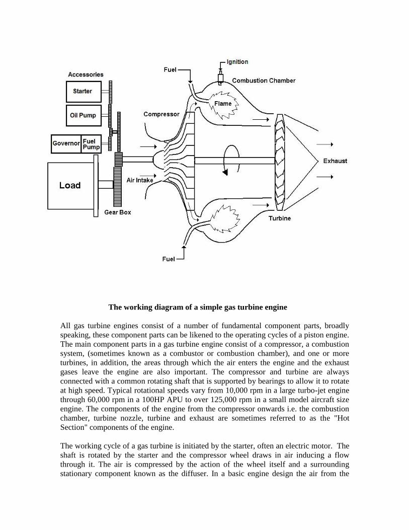
The working diagram of a simple gas turbine engine
All gas turbine engines consist of a number of fundamental component parts, broadly
speaking, these component parts can be likened to the operating cycles of a piston engine.
The main component parts in a gas turbine engine consist of a compressor, a combustion
system, (sometimes known as a combustor or combustion chamber), and one or more
turbines, in addition, the areas through which the air enters the engine and the exhaust
gases leave the engine are also important. The compressor and turbine are always
connected with a common rotating shaft that is supported by bearings to allow it to rotate
at high speed. Typical rotational speeds vary from 10,000 rpm in a large turbo-jet engine
through 60,000 rpm in a 100HP APU to over 125,000 rpm in a small model aircraft size
engine. The components of the engine from the compressor onwards i.e. the combustion
chamber, turbine nozzle, turbine and exhaust are sometimes referred to as the "Hot
Section" components of the engine.
The working cycle of a gas turbine is initiated by the starter, often an electric motor. The
shaft is rotated by the starter and the compressor wheel draws in air inducing a flow
through it. The air is compressed by the action of the wheel itself and a surrounding
stationary component known as the diffuser. In a basic engine design the air from the

compressor is passed to a combustion system. The combustion system is formed by a
chamber that mixes the air with fuel that is burned. The fuel air mixture is initially during
starting ignited by an electrical spark igniter, once lit it burns continuously until the
engine is shut down. The resulting combustion introduces heat in to the working cycle
creating gases that expand as they get hot and exit the combustion chamber with added
energy. The hot gases are directed through another stationary component a nozzle that
directs streams of hot gases that impinge on the turbine spinning it around. As the
compressor and turbine rotate, they accelerate under the combined action of the starter
and the hot gas stream, as speed increases the compressor discharge pressure also
increases overcoming losses and a point is reached where the cycle is self-sustaining and
no longer requires the assistance of the starter. The process continues and the rotor
eventually reaches a governed speed controlled by heat input and hence the fuel flow. A
load may then be applied to the engine and useful power extracted.
The gas turbine in its simplest concept may be likened to a windmill or turbine connected
to a fan or propeller. If this arrangement is rotated, wind from the fan would impinge on
the turbine and drive the whole thing around. This would be perpetual motion and of
course does not work! If heat is added (a source of external energy) between the fan and
the windmill then the air expands and hits the windmill with increased ferocity creating a
force that could assist in driving it around. In practice this still does not work as the losses
(air escapes and leaks around components) are very high and the net forces at
atmospheric pressure are very low. The individual component efficiencies could be
improved by enclosing them in a housing, making the fan in to an impellor shaped wheel,
sculpturing the turbine and tailoring the gas flow in to it. If this arrangement is spun
around by an external driving force (starter), and if it is spun fast enough with sufficient
heat added (but not too much as to melt the hot components), then the process will
become self supporting and the device runs on its own. This is the gas turbine principal, a
device has been created that drives itself and expels hot gases in its exhaust. If a
restricting nozzle is place in the exhaust, the gas velocity may be increased, a
combination of the pressure drop across the nozzle exit diameter and the accelerated mass
flow of gas though it creates a reaction on the whole engine assembly and it is known as
thrust. The gas turbine has become a simple jet engine.

Steps towards the realization of a working gas turbine

Cutaway view of a simple small gas turbine engine with can
combustor and radial turbine (Perkins Mars)

Air intakes
The air intake(s) on a small gas turbine engine may be found at the front or to the side of
the unit (the front in most cases is at the opposite end from where the exhaust gases
emerge). Air is guided into the engine by a simple bell-mouth shape or by one or two
converging ducts. Certain designs incorporate a partial enclosure built around the air
intake, this forms a plenum chamber or air box. A gearbox is often used to drive a
mechanical load and various engine accessories, this is normally placed at the front of the
engine (in the case of a single shaft engine) and the air is drawn in around it. The rear or
exhaust end of a gas turbine is generally hotter than the front, so all the temperature
sensitive devices are to be grouped towards the front. Certain designs use the intake air to
help cool the lubricating oil via an oil cooler radiator. Air intake filters are relatively rare
but certain models of ground based stationary engines come equipped with large
industrial type filter screens.
Gas turbine engine featuring side air intake (Rover 1S60)
A considerable amount of noise emerges from the air intake whilst a gas turbine operates;
it is possible to fit devices such as silencers and baffles to help reduce this noise. Gas
turbine silencers are often bulky and are generally only found fitted to ground based
stationary engines, compressors and generator sets where sufficient room is available to
construct an acoustic enclosure around them.
For their physical size and horse-power, gas turbine engines draw relatively large
amounts of air (compared to a piston engine of similar horsepower) into the compressor.

Considerable suction is present in the air intake that will create a hazard. There is also a
small pressure drop in the region of the compressor intake resulting from the converging
restriction and the acceleration of the air as it is induced into the compressor. The
addition of intake screens, enclosures or silencing devices may increase this pressure
drop through them and could adversely affect the operation of the engine. Attention
should be paid to their specification and design to prevent any significant loss of
performance. In the case of propulsion engines there is arguably a very small additional
thrust placed upon the engine due to the intake area static pressure being below that of
atmospheric.

Particle Separators
With curtain installations it may be necessary to fit a device known as a particle separator
to the gas turbine air inlet system. Particle separators consist of many small cells
approximately 30mm in diameter containing a vortex inducing arrangement. A small
screw helix type baffle mounted in a tube rotates the incoming air stream creating a
vortex. Heavy particles become "centrifuged" out to the outside diameter of the tube. Air
exits the tube from the centre via a snout arrangement, the unwanted heavier-than-air
particles pass out of the tube around the snout. Many individual tube separators are
placed in a box arrangement and the unwanted particles collect in the box and may be
extracted with a small blower unit or venturi excited with a compressed air nozzle.
A Particle Separator for fitment to a small gas turbine engine
The particle separator unit must be reasonably matched to the engine mass air flow, too
smaller a unit will result in excessive pressure losses and air intake drop reducing engine
performance. Two large a unit will result in poor filtration as the individual air flows in
the cells will not induce vortices of sufficient magnitude to separate the particles.

A particle separator cell showing the air flow paths
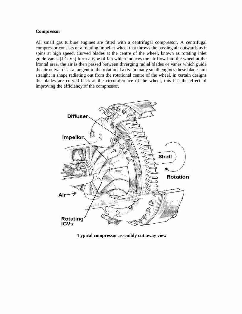
Compressor
All small gas turbine engines are fitted with a centrifugal compressor. A centrifugal
compressor consists of a rotating impeller wheel that throws the passing air outwards as it
spins at high speed. Curved blades at the centre of the wheel, known as rotating inlet
guide vanes (I G Vs) form a type of fan which induces the air flow into the wheel at the
frontal area, the air is then passed between diverging radial blades or vanes which guide
the air outwards at a tangent to the rotational axis. In many small engines these blades are
straight in shape radiating out from the rotational centre of the wheel, in certain designs
the blades are curved back at the circumference of the wheel, this has the effect of
improving the efficiency of the compressor.
Typical compressor assembly cut away view

Compressor diffuser showing divergent ducts (Casing removed)
The compressor impeller is surrounded by a ring of stationary vanes or blades which
receive vary fast moving air from it. The air is "expelled" from the compressor in to the
region of vanes surrounding it, the device that does this is called a diffuser. The diffuser
vanes slow down the air and remove some of the rotation from it, the effect of this is to
raise the static pressure of the air. The passages between the vanes form many small
divergent ducts through which the air passes, they slow down the movement of the air
and the static pressure is increased. Air leaving the compressor diffuser sometimes travels
between addition vanes, ducts or passages to further remove any rotational movement or
swirl before it is passed to the combustion system.

Typical small gas turbine engine compressor wheels
As the mass of air passes through the compressor system, the cross-sectional area through
which it passes becomes reduced, thus a given amount of air occupies a smaller volume
and hence the pressure has increased. The compressor can’t really be considered on its
own, it pressurizes the engine internal workings. A restriction on the compressor
discharge is essentially created by the turbine nozzle. The combined effect of the rotating
impeller and the stationary diffuser is to raise the air pressure by as much as four times
that of atmospheric pressure (The pressure at the engine intake). To do this, the
compressor has to rotate at very high speed, a wheel measuring about 5 inches in
diameter may spin as fast as 60,000 rpm and in doing so considerable power is required
to drive it. When the air is compressed inside the compressor mechanical work is done,
absorbing energy, as much as two thirds of the energy developed in a gas turbine is used
to drive the compressor. When air or any gas is compressed its temperature increases, this
is because mechanical work is carried out upon it, air leaving a gas turbine compressor is
raised in temperature for this reason. A typical compressor discharge pressure may be in
the region 40 PSI and at a temperature of 180 degrees C.
The compressor rotor operates inside a casing that is normally fabricated from aluminum
or magnesium alloy. The compressor case assembly may often incorporate a reduction or
accessory gearbox and may also form the air intake area as well. A smooth convergent
duct or bell-mouth is usually formed in front of the rotating central "eye" of the
compressor to aid the air-flow into it.
In order to get good efficiencies from small centrifugal compressors, the mechanical
running clearances have to be kept very small. The impeller has to function with
clearances of only a few thousandths of an inch between the rotating blades or vanes and
the surrounding casing in order to prevent air leakage. The circumference of the
compressor wheel runs close to the diffuser mounting assembly so that all the air flows
into the diffuser and does not leak out, passes between blades and reduces the through-
put efficiency. A gap exists between the actual diffuser blades tips and the tips of the
rotating compressor blade tips, this is to prevent turbulence and allow for a smooth

transition of air into the diffuser. In order to prevent unwanted resonance the numbers of
blades or vanes mounted on the compressor wheel and the diffuser assembly are arranged
to be dissimilar. A typical number of compressor blades may be 13 full blades and 12
half blades and 15 corresponding diffuser blades.
A type of compressor wheel exists called a shrouded compressor wheel. Here the issue of
small running clearances and leakage may be partially mitigated by placing a rotating
shroud around the compressor impellor vanes or around the rotating inlet guide vanes.
The compressor casing could then be described as “rotating with it”. A labyrinth seal may
also be employed to reduce air leakage. The shroud blocks air leakage between the
impellor vanes and helps maintain efficiency. Shrouded or partially shrouded
compressors may be found in some Garrett and early Rover gas turbine engines.
Shrouded compressor wheel

Compressor wheels are often made of grades of aluminum alloy, in many Garrett engines
they are manufactured from Titanium. The rotating inlet guide vanes are sometimes
manufactured from steel or stainless steel, in this case the compressor wheel is of a two
part construction. The rotating inlet steel guide vanes help guard against foreign object
damage (F.O.D.). F.O.D. is caused when the engine ingests foreign matter during
operation; particles ingested into the engine will cause damage to the compressor and
possibly cause the whole engine to catastrophically fail. Particles may also become
briefly trapped between the compressor and its housing as it rotates, this process can
damage the internal surface causing scratches and scoring. Scratches and scores will
increase the operating clearances of the compressor and hence reduce the efficiency of it.
Air intake grills or meshes normally protect against F.O.D. (And probing fingers!), they
should only be removed with caution. When a gas turbine engine is stationary and when
in storage, it is good practice to blank off the air intake areas and the exhaust to further
prevent the accidental ingress of foreign objects and contamination with dirt.
Aluminum compressor wheels are vulnerable to corrosion especially in older engines,
engines which have been standing in poor storage conditions or engines of unknown
history. It is always worth checking the compressor and intake area for corrosion and
evidence of damp storage conditions. When inspecting the air intake area of a small gas
turbine attention should be paid to the rotating inlet guide vanes, F.O.D may be indicated
by gouges, nicks or even missing portions of blades. A gas turbine engine should never
be operated with a damaged compressor as it may have become mechanically weakened
and is out of rotational balance.
Air compressors
The compressor system in many engine designs is deliberately made to operate at a larger
capacity than that which is required to run the engine efficiently, this feature enables the
engine to supply an external feed of compressed air. A portion of air flowing through the
engine is bled off from the compressor before it reaches the combustion chamber, the
feed of air delivered although at only moderate pressure (45 PSI) exhibits high mass flow
(Large volume of air per second flowing) and so contains high kinetic energy, this is
sufficient to drive a small external turbine. This supply of compressed air may be used for
aircraft engine starting or cabin air-conditioning. Many gas turbine engines are designed
to provide compressed air and shaft horsepower simultaneously, usually the shaft output
is de-rated during air bleeding. The engine is de-rated because less air flow is available
within the engine to keep it cool below safe limits.

The Blackburn Palouste engine discharges air as it runs and the air bleed is only shut off
during starting by a special valve. During starting, the compressor efficiency is very low
so the airflow through his engine has to be maximized to prevent it from overheating.
A gas turbine engine equipped with a compressor air bleed
Certain versions of the Rover 1S series gas turbine are equipped with an air valve which
is closed during starting and normal running, when an air supply is required the valve is
opened.
Small air compressor bleeds (A few percent of total mass flow) may be used with venturi
devices to induce greater quantities of air flow for the cooling of devices such as oil
coolers or electrical generators.
The Rover 1S60 fire fighting water pump unit employed an air bleed to aid in the priming
of the water suction hose.
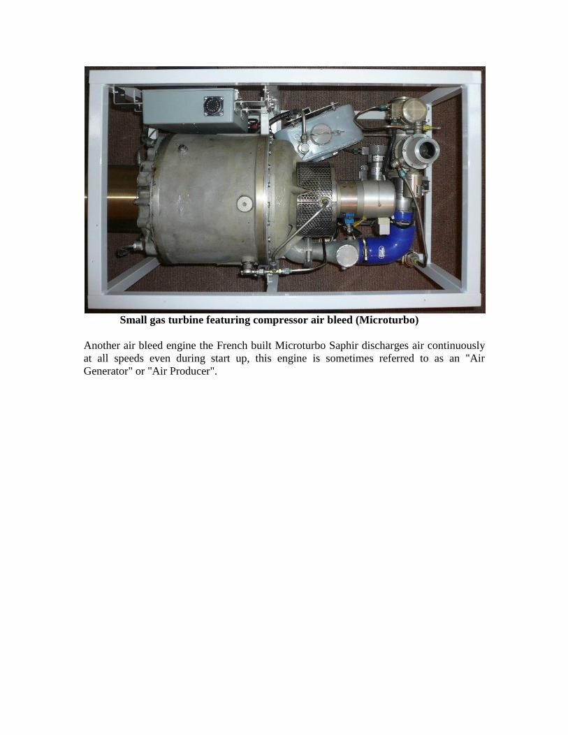
Small gas turbine featuring compressor air bleed (Microturbo)
Another air bleed engine the French built Microturbo Saphir discharges air continuously
at all speeds even during start up, this engine is sometimes referred to as an "Air
Generator" or "Air Producer".

Gas turbine compressor unit used for larger engine starting

Compressor surge-
The compressor of a gas turbine is designed to work within a range of operating
conditions and parameters. The engine must initially start, promote stable combustion,
accelerate to self-sustaining speed and obtain full load speed without the compressor
malfunctioning. The compressor “pumps” air through the engine, the passages and
components through which the air and combustion gases travel create a restriction and
hence a “back pressure” is placed upon the compressor outlet. The compressor is “loaded”
by these components. A situation may occur in a gas turbine where the compressor load
becomes too great for it to function correctly and aerodynamic failure occurs within it
and the pressure rise through it momentarily collapses. This condition is known as
compressor surge or stall and may also be likened to “cavitations” inside the compressor.
Compressor surge may occur during starting or acceleration phase if too greater amount
of fuel is supplied to the engine and the subsequent expansion in the combustion process
overloads the compressor as it fails to escape though the turbine nozzle. Compressor
surge is characterized as popping, sudden bangs, fluttering or low frequency buffeting
sounds. A small engine may recover from compressor surge as the operating parameters
fall back within the range of the compressor and stable running resumes. Severe cases
may cause the combustion to extinguish (Flame out) or the engine fails to recover
altogether and has to be shut down quickly and then restarted. Compressor surge rapidly
reduces the mass of air flowing into an engine, normally this will cause a loss in power
and the exhaust gas temperature to rise, if unchecked, this will cause damage to the
engine. Common causes of compressor surge include, malfunctioning fuel control
systems, incorrectly set up air bleed systems and dirty, damaged or fouled compressor
components. Sudden transient changes to compressor loading (i.e. opening and closing
bleed systems) may also give rise to compressor surge.

Individual compressor stage loading:
The tendency to compressor surge and stall may be reduced by decreasing the load and
variation placed upon the compressor stage or stages within the engine. Many small gas
turbines employ only one compressor stage. This stage is normally loaded close to its
surge limit, particularly in the case of air bleed engines which are required to deliver a
given mass flow and pressure for external use. It is possible to construct two tandem
centrifugal compressor stages (one feeding into another) and operate them at lower
individual stage load to reduce the tendency to surge. Some models of Garrett engine
(GTCP85) use a two-stage compressor to produce a pressure rise of some 45 PSI and
operate a simple on-off bleed valve arrangement. This engine is able to cope with the
changing air bleed demands. A similar bleed of air is obtained from a single stage
Palouste MK102 engine, due to the single stage, a calibrated regulating bleed valve
system is needed to manage the airflow through the engine and prevent surging.
Gas turbine engine featuring a twin stage compressor

Twin stage compressor: Garrett GTP70 APU
Compressor bleed valve (Palouste)
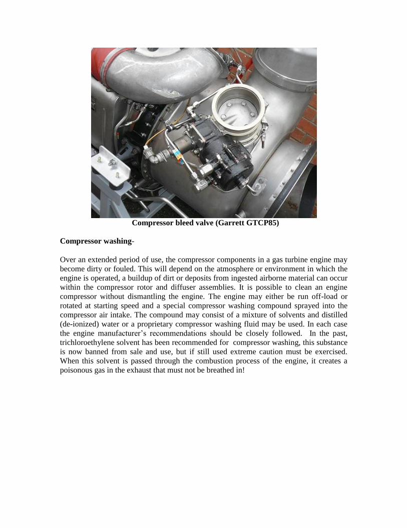
Compressor bleed valve (Garrett GTCP85)
Compressor washing-
Over an extended period of use, the compressor components in a gas turbine engine may
become dirty or fouled. This will depend on the atmosphere or environment in which the
engine is operated, a buildup of dirt or deposits from ingested airborne material can occur
within the compressor rotor and diffuser assemblies. It is possible to clean an engine
compressor without dismantling the engine. The engine may either be run off-load or
rotated at starting speed and a special compressor washing compound sprayed into the
compressor air intake. The compound may consist of a mixture of solvents and distilled
(de-ionized) water or a proprietary compressor washing fluid may be used. In each case
the engine manufacturer’s recommendations should be closely followed. In the past,
trichloroethylene solvent has been recommended for compressor washing, this substance
is now banned from sale and use, but if still used extreme caution must be exercised.
When this solvent is passed through the combustion process of the engine, it creates a
poisonous gas in the exhaust that must not be breathed in!

Compressor washing with fluid (Rover 1S60)

Combustion system
Air emerging from a gas turbine compressor diffuser is passed to the combustion system
where it is heated by the burning of fuel; this process provides the heat energy that drives
the working cycle of the engine. In the combustion chamber the heated air expands, gains
kinetic energy, and the pressure remains almost constant. It is the heat input to the gas
turbine cycle that propels the engine, normally a flame provides this heat, however if
some other form of heat input could be obtained e.g. an electric heater or heat exchanger
(Feed from an external heat source) with sufficient capacity the engine would run. In
practice the heat required in the small space of the combustion chamber is best provided
by a flame with a central temperature of over 2000 degrees C.
The combustion arrangements in small engines basically consist of three types, a can type,
an annular type or a radial type.

1. Can type combustion chamber (Combustor).
This is the simplest of combustion arrangement and consists of a cylindrical metal
can shaped housing containing a heat-resisting alloy metal liner or flame tube. Air
from the compressor is ducted to the combustion chamber by the casing surrounding
the compressor diffuser outlet. This casing may surround all the hot parts of the
engine and hence reduce the outside surface temperature to an acceptable level.
Small gas turbine engine incorporating a can-type combustion chamber
The combustion chamber liner consists of a heat resistant metal cylinder that is closed at
one end by a dome shaped cap. Fuel is admitted to the combustion chamber in the form
of a finely atomized spray from a nozzle at the closed end where it is ignited by a special

spark plug. Air from the compressor flows around the outside of the liner and between it
and the outer combustion chamber casing. A series of holes or orifices in the liner admit
the air into the central region of the liner where it mixes with the fuel, burns and sustains
combustion. The burnt exhaust gases exit through the open end of the liner and are ducted
to the turbine assembly. The holes in the liner are arranged to provide air for the
combustion of the fuel and also additional larger holes towards the open end admit more
air for cooling of the combustion products. The flame temperature inside the liner may
reach some 2000 degrees centigrade, this is too high for the hot section parts of the
engine (Turbine Nozzles, Turbine and supports) to cope with and so the additional
dilution cooling air is required to bring the temperature down. A typical turbine inlet
temperature may range between 400-900 degrees centigrade depending on the type of
engine and the load placed upon it. Only about 25% of the air entering a gas turbine is
burnt with the fuel, the rest is used for cooling. The detailed arrangements of the holes
becomes complex, they are required to produce swirl within the liner and stabilize
combustion over a range of operating conditions. The surface of the liner is also kept cool
by rings of very small holes that provide a protective boundary layer of cool air within
the combustion chamber liner. The hole or orifice sizes are arranged so that the pressure
drop between the outside and inside of the flame tube is kept to a minimum; any drop in
pressure at this point will reduce the efficiency of the engine and place an unnecessary
load upon the compressor.
The flame tube/liner arrangement holds a stable flame within the combustion chamber
which unlike a piston engine, burns continuously. The pattern of airflow around the fuel
nozzle is carefully arranged so that a turbulent recirculation motion thoroughly mixes the
air and fuel spray together and anchors a stable flame in place. Ignition of the fuel is only
required once during the starting of the gas turbine engine.
The flame tube is made of a corrosion and heat resistant metal such as stainless steel or a
high temperature nickel-alloy such as Nimonic. Over a period of time the tube may
became distorted due to thermal stresses and heat cycles. Small amounts of distortion
depending on the engine type may be permitted. Cracks due to thermal shock and fatigue
can also form in the flame tube and often between the holes and orifices, these may be
repaired by welding (detailed in the manufacturer’s overhaul or maintenance manual) if
not severe. The overhaul or maintenance manual for a particular engine will normally
detail acceptable limits of distortion and cracking for the combustion chamber and hot
section components.
The combustion chamber liner will be suspended at a number of points inside the engine.
The liner will normally be allowed to "Float" slightly and may appear loose, and rattle
slightly, this is to allow for thermal expansion and so prevent the liner from distorting
unnecessarily.
During the prolonged operation of the combustion chamber, carbon deposits may build
up in the flame tube and around the burner nozzle. Depending on factors such as fuel type
and burner design, carbon deposits will build up and the combustion process
detrimentally effected. Carbon formations around the burner upset the fuel spray pattern

and reduce the atomization quality. Carbon deposits may also block or modify the air
holes, this leads to less efficient air distribution. If the spray pattern is very poor the
resulting flame may continue outside the combustion chamber area and create an uneven
temperature distribution around the turbine and associated components, this will lead to
the eventual burning of these components and failure. It is possible to "De-carbonize"
combustion chamber components, great care is needed as devices such as fuel burner
nozzles and igniter plugs should be not brought into contact with abrasive materials or
tools.
Igniter plugs and burner nozzles should only be cleaned with soft materials soaked
mentholated spirit or electrical cleaning solvents.
A single can type combustion chamber exhibits a number of advantages over other types.
The main advantage is simplicity, a single burner is installed in the engine and the liner
can be easily removed for inspections and maintenance. In small engine designs,
achieving efficient and complete combustion becomes difficult as the internal dimensions
and burning length required are relatively small. A cylindrical can type chamber holds a
single relatively large flame for a given size of engine.
The disadvantage of a can combustor is that the engine may not be found to be as
compact as with other types. The engine will not be symmetrical about its axis, for some
small starter units that may be mounted on larger engines, compactness, weight and
minimum external dimensions are important.
Can type combustion chamber inc. Atomizer and igniter plug

A single can type combustion chamber is fitted to many Garrett engines and also the
Rover 1S series uses a single can combustion chamber. The Perkins Mars/Solar T41 is
another gas turbine which employs a single can type combustor. Occasionally engines
use two can type chambers mounted diagonally opposite each other, an engine once built
by the company Auto Diesels is constructed in this way.
Twin combustion can engine (H & S Stad 250)

Hants and Sussex STAD250

Can-type combustion chambers (Garrett)

2. Annular combustion chamber
An annular combustion chamber is required to do exactly the same function as a can-
type unit but is physically arranged in a different way to reduce the overall size and form
of the engine. The combustion chamber liner forms a toroid or “doughnut” shape and is
rapped around the axis of the engine. Instead of a single fuel burner nozzle a ring of
multiple fuel nozzles are deployed. The combustion chamber liner is often arranged to
curve the combustion gases back on itself, in which case it is referred to as a "reverse
flow combustion chamber". A reverse flow combustion chamber saves on the overall
length of an engine and provides a longer burning area for the gases to travel through.
Small Gas Turbine engine incorporating an annular reverse-flow combustion
chamber

The annular reverse flow combustion chamber arrangement requires a number of fuel
burner nozzles to be placed at the back of the engine around the exhaust circumference.
Fuel is distributed to the burners by a pipe manifold or by drillings in the combustion
chamber outer casing. The spray patterns from the individual burners are of a cone or fan
shape or in the case of a Lucas aerospace engine, five burners produce flat fan shaped
patterns that are arranged in the form of a pentagon. One or more igniter plugs are placed
next to the burners to initiate combustion, once one burner lights up the flame spreads to
the others rapidly.
Air holes are placed in the combustion chamber liner in a similar manner to that in the
can type system. Small holes in the nozzle/burner region provide air for combustion and
then larger holes down-stream provide cooling dilution air before the gases are passed to
the turbine system. Air that has been bled from the compressor may also be supplied to
the burners directly to assist in the atomization process.
The annular combustion chamber reduces the overall size of an engine but it is more
integrated into the engine construction and is therefore often more difficult to remove,
service and inspect.
The Rotax/Lucas Aerospace gas turbine starter/auxiliary power unit uses a reverse flow
combustion chamber with five burners. The Microturbo Saphir and the related Plessey
Dynamics "Solent" gas turbine starter also uses a reverse flow arrangement with eight
burners. The Solar T62 "Titan" unit is fitted with a reverse flow combustion chamber and
six vaporizing burners plus torch igniter.

Annular combustion chamber (Lucas)

3. Radial combustion chamber
A third type of combustion system consists of a radial layout. The radial combustion
chamber was pioneered by the French company Turbo-Mecca and can be found in a
number of their designs. The German company Man-turbo (MTU) formally BMW and
the Swiss company Saurer also used this combustion chamber layout.
Small gas turbine engine fitted with a radial disc type combustion chamber
(MAN6012)
The combustion chamber liner is arranged to form a radially disposed chamber around
the shaft that connects the compressor to the turbine, fuel is first passed into ducts inside
the shaft. The fuel is then admitted in to the combustion chamber through the turning
shaft from a series of radial drillings placed in it. As the shaft rotates at high speed, the
fuel is thrown outwards from the drillings and a fine disc shaped spray pattern results.

The fuel spray is ignited and burned with a similar combustion air and cooling air
distribution ratio to that of the other combustion chamber types. The air distribution is
created by holes and orifices forming rings in the combustion chamber liner walls around
the shaft axis. The hot gases from the combustion process are guided by the liner
outwards and along the engine axis or back towards the centre depending on the type of
turbine wheel used. The whole radial liner is enclosed in an outer casing that is
pressurized (and cooled) with air from the compressor.
Fuel has to be supplied to the combustion chamber through the engine shaft, this requires
a seal arrangement at the cold end near the compressor to ensure that it does not leak out
into the other engine systems i.e. the oil supply to the bearings.
The Blackburn Palouste, Artouste and Nimbus engines all use this arrangement, as do
other Turbo-Mecca engines and some Continental US built units. The radial layout makes
for a symmetrical engine around its axis similar to the annular combustion chamber
layout. The fuel pump required needs to maintain only moderate pressure, however due
to centrifugal force generated by the high rotational speeds, the actual injection pressure
into the combustion chamber is very high. A high fuel pressure helps to aid the
atomization process for a cleaner and more complete fuel burn.
Blackburn/Rolls Royce Palouste engine

Mechanical layouts
Most small APU size gas turbine engines adopt a simple single shaft layout, that is the
compressor turbine also drives the load. The overall mechanical layout is dependent on
the type of combustion chamber and turbine or turbine(s). A number of differing
configurations are possible with these components and various manufacturers favor
differing layouts.
Typical small gas turbine engine mechanical layouts

Working diagram of a simple turbo-jet engine
Gas turbines are often classified as “Turbojet”, Turbofan” or “Turbo-shaft” engines,
small APUs are generally considered to be turbo-shaft units. Small turbojets intended for
the propulsion of UAVs (Unmanned Aerial Vehicles) and drones are similar in design to
APUs and in some cases have been derived from them. The Rover TJ125 also known as
the Lucas CT3201 is a development of the twin shaft 2S100 series APU size unit.

Rover TJ125/Lucas CT3201 Turbojet
Lucas CT3201 layout (reverse flow combustor + radial turbine)

Turbines
The turbine wheel or wheels in a gas turbine serve a number of purposes, in all cases one
or more turbines are used to drive the compressor via the connecting shaft, this is what
sustains the engine operation. External power from the engine may also be obtained from
this shaft (via a reduction gearbox) or an additional turbine is used which is mechanically
free from the turbine driving the compressor.
There are two types of turbine that are used in small gas turbine engines, the radial-inflow
turbine and the axial-flow turbine. Depending on the design of engine either type can be
found, notably in the Lucas Aerospace GTS/APU and Rover 2S150 both types are used
in the same engine.
Types of turbine wheels found in small gas turbines

Axial flow turbine exhaust view
Radial flow turbine exhaust view

Axial flow turbine
The axial flow turbine wheel consists of a wheel with a number of small angled blades
mounted around its circumference. The hot expanding gases from the combustion
chamber are directed onto the blades by a ring of similar static blades or vanes forming a
nozzle. The passage between the blades form many small nozzles which ensure that the
gases impinge on the turbine blades in the direction of rotation of the wheel. The turbine
blades are a complex shape, the operating mechanism of the turbine is partly that of an
impulse turbine and partly as a reaction turbine. As the gas strikes the turbine blade it
gives up a portion of momentum to the blade causing it to move. The gas flow over the
blades is such that the pressures on each side are different causing a reaction on the blade
and forcing it two move. The blades can be considered to be airfoils or tiny wings, the
“lift” produced per blade results in rotational torque.
The combined effect of the stationary turbine nozzle and the rotating turbine wheel is to
reduce the pressure, velocity and temperature of the gases flowing through it. Work is
extracted by the turbine and so the energy in the gas stream is reduced. The turbine
assembly may be considered to be similar to that off the compressor but working in
reverse.
The axial flow turbine wheel turns inside a very close fitting shroud, the gap between the
shroud and the turbine blade tips must be kept as small as is practicable. A small
clearance between the blades and the shroud ensures no significant amounts of gas
bypass the turbine reducing the efficiency of the stage. In small engines gaps measuring
as little as 5 thousands of an inch are possible. The turbine wheel and associated nozzle is
manufactured from a high temperature alloy such as Nimonic or other high temperature
steels. The turbine has to withstand very high temperatures, resist corrosion, high
rotational forces and remain within very tight mechanical dimensional tolerances. Over
the operating life of the engine the wheel will experience many heat cycles when the
engine is started and stopped, these thermal cycles must not have a detrimental effect on
the wheel. Eventually over time the wheel may suffer cracking and the dimensions may
expand due to creep, periodically as part of an engine overhaul the wheel must be
checked and inspected. The blade tips may also become eroded and burnt on high life
turbine wheels that will reduce the efficiency.

Radial flow turbine
A radial flow turbine wheel may be described as an impellor type compressor wheel
working in reverse. A ring of tangentially arranged static vanes form nozzles through
which the hot gasses from the combustion chamber are directed on to the impeller shaped
wheel around its circumference. The gases initially flow in the direction of the wheel
rotation and impinge on the impellor radial vanes. The gases flow inward and additional
curved rotating blades then guide them out along the rotor axis and to the engine exhaust
outlet.
A radial flow turbine wheel is almost universally used in automotive turbo-chargers, it is
more efficient than a single stage axial flow wheel. It has the advantage that the running
tolerances are more relaxed, as the running clearances around the impellor blades are
found to be less critical on this type of wheel.
Many small engines use radial inflow turbine wheels, they are very common in Garrett
APUs, the German BMW 6012 uses this type, Saurer GT15 is equipped with this type
and they can also be found in some Lucas/Rover engines. The larger KG2 industrial gas
turbine is also fitted with a single radial inflow wheel.
Due to the favorable mechanical clearances that can be adopted with radial flow turbine
wheels, the configuration allows for a particular mechanical engine layout. The
compressor and turbine are mounted back to back on a common shaft and separated only
by a baffle and a seal around the shaft. The bearings supporting the shaft are both placed
outboard of the wheels in an "overhung or cantilever configuration". The advantage of
this arrangement is that the bearings are placed well away from the "Hot Section" of the
engine. This arrangement reduces the temperature of the bearings and exhibits advantages
in terms of life and heat build up. The turbine wheel is placed furthest from the bearings
and so any radial movement will be at a maximum at this point. To allow for a small
amount of radial movement the clearances around the turbine wheel are relatively large,
for this reason a radial inflow wheel is favored. The gas flow around the wheels is also
straight forward as it exits the compressor and enters the turbine around the
circumference, keeping the whole configuration as short as possible.
A second advantage of an overhung bearing arrangement is that the hot section
components do not carry a bearing system and so may be removed for inspection without
the rotor assembly, associated bearings and seals being disturbed.

Over-hung gas turbine rotor bearing support
Depending on the design of the engine one or more axial flow turbines or one radial
inflow turbine may be used to drive the compressor. Most small gas turbines consist of a
single shaft layout, i.e. the rotational horsepower developed by the engine is extracted
directly from this single shaft. A gearbox is used to reduce the rotational speed so that it
may be used to drive a suitable load. Mechanical loads on small gas turbines often consist
of electrical generators, pumps or in some cases air compressors. The gearbox is also
used to drive various engine accessories such as fuel and oil pumps. When using a single
shaft engine, care must be taken to ensure that no significant mechanical load is placed
upon the engine until it has successfully started and accelerated to governed speed.
Certain types of DC generators are relatively stiff to turn due to high current brush gear,
in this case a centrifugal clutch should be used so that the engine does not drive the
generator until it has gathered speed, this also relieves the load on the starting system.
One example of a single shaft gas turbine directly drives a second compressor, during
starting the second compressor is blocked off by a valve and effectively stalled to prevent
it absorbing power and loading the engine. Note: Compressors driven by free turbines
must never be stalled or an over-speed condition and failure may result.
A remarkable system adopted by the company Saurer uses a fluid coupling to engage a
load on to the GT15 engine. A fluid coupling connects the gas turbine to a compressor

unit, during starting and other operations the fluid coupling is drained of fluid and so does
not transmit drive to the compressor. When the compressor is required, fluid is passed
into the coupling, it fills up and the drive is transmitted. The fluid used is in fact the
kerosene type fuel, the Saurer GT15 gas turbine uses fuel for lubrication, the power
transmission and of course for combustion.
Hydraulic fluid coupling used to engage drive to a load compressor (Saurer GT15)

Gas turbine incorporating fluid drive coupling (Adolph Saurer GT15)

Free power turbine (twin-shaft) engine
A few small gas turbines adopt a twin shaft layout. Here a second turbine wheel
mechanically free from the compressor turbine is used to extract power from the engine.
Usually the engine accessories are driven from the compressor turbine to enable this part
of the engine to start up. A gas turbine engine that supplies its hot gases to turn a free
turbine is sometimes referred to as a "Gas Generator". As the gas generator runs up to
speed the hot exhaust acting upon the free turbine gradually accelerates it up to speed,
this may take place with a mechanical load already applied.
A small twin-shaft gas turbine engine incorporating a free power turbine stage

Twin shaft gas turbine engine incorporating a free power turbine stage
(Rover AAPP MK10401)
The main use for this arrangement is in gas turbine starter units (GTSs). A gas turbine
starter is basically a small turbo shaft engine which is used to provide direct mechanical
effort to spin up a much larger aircraft propulsion engine in a similar way to that of an
electric starter motor. The small gas generator section of the GTS is started electrically
which intern spins a free turbine, the free turbine is connected to the propulsion engine
through a reduction gearbox. As the main engine runs up to speed the starter can be shut
down by means of a centrifugal switch, this function is set to operate when the free
turbine reaches a pre-determined speed. A one way over-running type clutch prevents the
started propulsion engine from continuously back-driving the turbine wheel after the start
cycle is complete and the GTS has shut down.
Prototype Rover P6 with 2S150 engine subsequently developed into AAPP Units

The Plessey "Solent" gas turbine starter unit is an example of a small free turbine engine.
This unit was used to rotate the High Pressure spool in a RR Spey engine and was fitted
to the now obsolete MD Phantom F4 aircraft. The Solent carried an intermittent rating of
some 70 horsepower for the maximum duration of one minute. This rating is mainly due
to a one-shot oil lubrication system. The one shot system consists of a simple oil metering
Small 70HP twin shaft gas turbine (Plessey Solent MK101)
mechanism operated by air from the compressor. The Solent, gas generator section spins
at 60,000 rpm and the free turbine cut of speed is 50,000 rpm. A twin stage epicyclic
reduction gearbox with a ratio of 11:1 is used to provide a low speed output rotation to
drive into the RR Spey accessory gearbox.


A unit made by Lucas Aerospace is used to start the RR Pegasus engine in a Harrier
VTOL fighter jet. The engine was developed from the Rover twin-shaft car engine. This
unit drives through a free turbine and twin epicyclic gearbox to provide an output of
some 80 shaft horsepower. The free turbine is also used to drive a generator without it
turning the Pegasus engine over. The free turbine is disconnected from the main engine
and a power turbine governor is used to maintain an output speed of 12,000 rpm via an
additional train of gears. In this case the gas generator spins at about 55,000 rpm, during
the engine starting phase the gas generator speed is increased to 77,000 rpm to provide
the extra power needed to start the Pegasus engine. The GTS is able to convert from one
mode to another by making use of an elaborate system that applies a brake to the free
turbine before coupling it to the stationary Pegasus engine with a dog-type clutch.
Lucas Aerospace twin-shaft gas turbine engine (CR201)

Lucas twin shaft CR201 APU
Great care must be taken when operating many free turbine engines, if they are started
with no load applied to the free turbine, it will over-speed with potentially catastrophic
results. The Solent unit can only be operated in a stand alone mode only if the free
turbine and output gearbox are first removed. The engine then consists of a gas generator
which will govern itself at 60,000 rpm. GTSs are normally tested on a special rig, the
GTS mechanical output is used to rotate a large flywheel and brake or dynamometer
equipped load.
The Lucas engine is fitted with a governor driven from the free turbine, this allows the
unit to be operated complete with no external load applied. This mode of operation is first
selected by opening a solenoid valve that enables a power turbine governor. During a
Pegasus starting operation the GTS bypasses the governor, this must not be allowed to
happen if no load is applied to the output i.e. when the GTS is operated stand-alone.
Most larger gas turbines for use as helicopter and turbo-prop engines are also of the twin
shaft type, this allows the gas-generator to be started without the main rotor system or
propeller placing a load upon it. Common examples such as PW PT6, Turbomeca Arriel,
Arrius, GE T58, RR Gnome, Lycoming T53, Lycoming T55 all adopt this layout.

Lycoming T55 twin-shaft helicopter engine
There are exceptions to the twin shaft layout in both helicopters and airplanes. The
Turbomeca Artouste and Astazou engines drive helicopter rotors systems from just one
shaft. These engines are started conventionally whilst disconnected from the rotor
systems, a special centrifugal clutch is used to take up load once the engine has past self-
sustaining speed and is running at idle. The RR Dart turboprop and the Garrett TPE331
turbo-prop units also operate as single shaft engines. Starting is achieved by “feathering”
the driven variable pitch propellers so that they place minimal load upon the engine.
RR Dart single-shaft turbo-shaft engine

Exhaust systems
Once the hot gases contained within a gas turbine have passed through the turbine(s) they
are discharged to atmosphere. The exhaust emerges through a divergent duct that is
sometimes bent around to direct the exhaust in a particular direction. The exhaust is hot
and is traveling very quickly, it is potentially dangerous and must be is directed away
from airframes, equipment and people. In the case of gas turbine starters, power is
normally taken off rearward via a gearbox so the exhaust is ducted sharply around a 90
degree bend and out to the one side. Vanes or louvers are sometimes placed in exhaust
ducts to help guide the gases, reduce turbulence and eddies which could reduce the
efficiency of the engine.
Gas turbine exhaust ducts Left: APU Right: Turbojet Engine
An important operating parameter of any gas turbine engine is a measure of the emerging
exhaust gas temperature or EGT. The EGT of small gas turbine will vary considerably
from type to type and it also depends upon the load and operating conditions placed upon
the engine. The EGT is also a very important measure of the health and efficiency of the
engine. During start up there is an often an excess of fuel available for combustion and a
deficit of air emerging from the compressor, the engine will momentarily run hot until it
gathers speed and reaches self-sustaining speed when more air becomes available for
cooling. As a load is applied to a running engine, the airflow passing through it remains
almost constant but increased fuel is burned in order to maintain the same speed under a
load, this results in a higher exhaust temperature. All gas turbine engines have specified
limits for maximum starting and running exhaust temperatures, these limits should not be
exceeded. A typical starting temperature for a GTS could be as much as 750 degrees C,
this is because this type of unit is required to start and run up as quickly as possible. Off
load Garrett APU type engines run as cool as low as 280 degrees, off load the Rover
1S60 runs about 400 degrees, a Lucas GTS can run as hot as 500. As a gas turbine starts
the exhaust temperature normally rises rapidly after "Light Up", reaches a peak and then
settles back to a lower value when idle speed is reached.
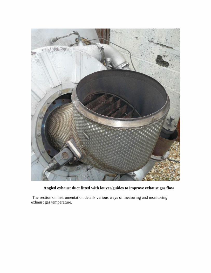
Angled exhaust duct fitted with louver/guides to improve exhaust gas flow
The section on instrumentation details various ways of measuring and monitoring
exhaust gas temperature.

Silencers
The operating principals of exhaust and air intake silencers is essentially the same.
Acoustic splitters consisting of absorbing glass fiber packing contained with perforated
metal sheet are placed in the intake air path and exhaust outlet. In the case of an exhaust
silencer the usual construction material is stainless steel to prevent corrosion and resist
the high exhaust temperatures.
Engine housings and enclosures may also contain acoustic lining consisting of perforated
sheet encapsulating glass fiber insulation. It is also possible to user acoustic expanded
foam and high density rubber foam materials such as “Insul-sheet” to line the enclosure
where the exposure to heat is minimal. High density rubber matting is also available to
provide vibration damping and absorption on enclosure panels and covers. A
disadvantage with many sound insulation materials is that they provide in most cases
unwanted thermal insulation enclosures should be well ventilated. Fans may be needed
after engine shut down as stored heat will remain in the enclosure for some time.
Insulation materials are available with a special layered construction of different density
and compositions to help augment sound reduction and damping.

The illustrations below show examples of silencer units fitted to gas turbines
rated up to 150BHP. Typical exhaust and intake noise attenuation 10dB.
Small gas turbine exhaust silencer units (Large unit approx 1.5m high)

Acoustic splitters in exhaust unit
Cylindrical exhaust silencer unit (L=750mm)

Air intake silencer unit featuring acoustic splitters

Cooling
Most types of internal combustion engine require cooling of some form or another, in the
case of a piston engine they are normally air or water cooled employing fans or radiators.
In the case of the gas turbine engine, it may be considered to be "Self cooled". The
working medium through out a gas turbine engine is air and there are large quantities of it.
The majority of the air will flow from the compressor into the combustion chamber, this
air is partly used for combustion and partly used to cool the combustion gases before they
enter the turbine. Air is also used to cool a number of other crucial areas within the
engine structure.
In certain designs of engine, the vanes or nozzles which divert the combustion gases onto
the turbine are actually hollow. Compressor air passes through the nozzles to cool them
and to ensure that they remain within an acceptable temperature range. The turbine
nozzle guide vanes are the first to receive gases from the combustion chamber, this is one
of the hottest part of the engine. As the gases pass through the turbine nozzles and turbine
they reduce in temperature and expand as energy is extracted from them.
Turbine Nozzle Ring (Stator) featuring air cooled guide vanes
Air bled from the compressor is also directed onto the surface of a turbine wheel to
reduce its temperature and prevent excessive heat reaching the shaft to which it is
attached. Air may also be ducted to the turbine end bearing to keep it cool.

Vibration and Balance
Compressors and turbines rotate at high speed, in the case of a Saurer GT15 APU the
maximum speed is some 85,000 rpm. Before assembly the high speed rotating
components of a gas turbine are accurately dynamically balanced. Dynamic balance
refers to the balancing of a wheel radially and also along its axis. It is possible to
statically balance a wheel so that the centre of mass lies on the rotational axis, however
the mass distribution may not be even on each side of the wheel. If the wheel is
considered as a whole it is balanced, but if each side of the wheel is considered separately
an imbalance can be found. If the wheel is rotated an out of balance force is created
which must be corrected.
Balancing of rotors
Turbine wheels and compressors should be balanced on a special dynamic balancing
machine or rig built for the purpose. The machine rotates the wheels at a few hundred
rpm and by means of a number of transducers; it detects the resulting vibration generated
by any imbalance. The transducer signal is displayed on an oscilloscope or other
indicating device. By placing small temporary weights on to the wheel (Often plasticine),
the balance may be improved and the vibration signal reduced. Once balanced with the
temporary weights, the wheel is machined at a position radially opposite the location of
the weights. The machining is carried out on both sides of the wheel and the balancing
weights removed; the balance of the corrected wheel is then re-checked on the machine.

Dynamic balancing machine
Turbine wheels and compressors are manufactured with regions of metal which are
intended for removal to aid balancing. A circular ridge is provided on each side of an
axial turbine disc, portions of which are ground off when the wheel is balanced. A similar
ridge is also provided on the rear face of a compressor wheel. Small holes may also be
drilled into the central boss near the front of the wheel and small chunks can also be
removed from the wheel circumference. When inspecting a wheel; missing portions
should be checked carefully to ensure that they are identified as balancing points and not
the result of damage.
Small gas turbine engines operate at such high speeds that the rotation of the main shaft
gives rise to a characteristic whine. As the engine spools up to speed, a distinctive whistle
is produced by the action of the compressor, at governed speed this is relatively high at
for instance a frequency of 10 KHz, a lower whine or audible tone may also be heard
which is proportional to the rotation of the shaft. An engine turning at 60,000 rpm
revolves 1000 times per second; this gives rise to an audio tone of 1 KHz. A running
engine exhibiting good balance will produce a note quieter than that of an inferior unit.
Poor balance may manifest itself as harmonic sounds and resonances as the engine spools
up and down. Bearing assemblies also play a part on the effects of balance; the bearings
support the rotational shaft and so aid in dampening vibration and resonances.
High-speed rotating shafts exhibit what is known as “critical” speeds. At certain speeds
interaction occurs between the bearings supporting the shaft, the shaft stiffness and the
rotating mass of the wheels. This interaction results in vibration and resonances, as the
rotor turns it does not spin true but instead whirls (revolves eccentrically) and distorts
slightly, many engines accelerate through these speeds and are carefully designed so that
they do not suffer any detrimental effects. A gas turbine should not be operated
continuously at a shaft critical speed as wear and damage to it will result.
If it is suspected an engine is out of balance due to rough running or vibration it should
overhauled and the balance of the rotor checked.

Fuel efficiency
Compared to many other prime mover power plants small gas turbines are not very
efficient sources of power. This is one of the reasons why there application is generally
restricted to aircraft where they find advantages in terms of size, weight and the fact they
burn the same fuel as the propulsion engines. Larger gas turbines rated at many thousands
of horsepower offer much improved efficiency.
The main reasons for poor overall fuel efficiency in small gas turbines can be attributed
to the following causes-
1. Small gas turbines that operate with only a single stage compressor or lightly loaded
two-stage compressor raise the air pressure by a maximum of about four times that of
atmospheric pressure. In heat engines the more the air is compressed the more it can
expand when heated, also the more energy is released. Engines with higher pressure
ratios burn less fuel as more energy is released during the increased expansion. The
pressure drops as the gases flow through the turbines and eventually becomes
atmospheric as it leaves the exhaust. More turbine stages (Extracting more power) are
possible with larger higher pressure ratio engines.
2. When the air is heated by combustion in a gas turbine the expansion is determined by
the temperature rise. The higher the inlet temperature to the turbine, the more expansion
can take place in the turbine and more power is released. If the gases are cooled before
entering the turbine then energy is lost which is not available to develop mechanical
power. Larger engines with more sophisticated cooled turbine nozzles will cope with a
higher turbine inlet temperature.
As a small gas turbine engine runs, much of the energy resulting from the burning of fuel
ends up as waste heat in the exhaust. It is possible to improve the efficiency of the engine
by re-cycling some of this waste heat. A heat exchanger is used to extract heat from the
exhaust and use it to raise the temperature of the air entering the combustion chamber.
Less fuel is required to be burnt in the combustion chamber for the same turbine inlet
temperature and so the engine burns less fuel for a given power output.
Heat exchangers that are fitted to small surplus gas turbines are rare, they are often
complicated and bulky. The difficulty in successfully producing a heat exchanger was
one of the reasons for the ultimate failure of several automotive gas turbine projects. Heat
exchangers may also have large thermal inertia (i.e. they store as well as transfer heat)
and so will limit the engine's response to load changes.

Small gas turbine fitted with heat exchanger/recuperator (Capstone C60)

Small gas turbine architectures
Typical small gas turbine engine (Garrett GTP30-67)
A typical small gas turbine engine rated at 40HP (25Kw) is shown above, here a
complete running unit is formed by mounting all the systems and accessories on to a
reduction and accessory gearbox housing. A hydro-mechanical fuel control system is
used here and a wet sump system is employed for lubrication.
Layouts and architectures in small gas turbine engines vary considerably from model to
model.

Disassembled small gas turbine engine employing externally mounted accessories.
(Microturbo)
The accessories of this small gas turbine producing up to 50HP equivalent of air delivery
are externally mounted and not driven by the engine but instead by an electric motor. All
the units shown are required to operate the engine in a self sufficient manner. The fuel
system is controlled by an electronic control unit (ECU).

Complete assembled 50HP gas turbine engine

Micro-turbine gas turbine engines
Simplified schematic of a typical micro-turbine gas turbine engine
The above diagram illustrates a typical micro-turbine gas turbine installation. Micro-
turbines occupy a gas turbine engine class of their own, they are not derived from aero
engines as they are generally small in comparison and constructed as stationary engines.
Micro-turbines compared to established large scale static power generation are very small
in size hence the name micro gas turbine. Micro-turbines are manufactured in range of
sizes from 30 to 200kw.
A micro turbine rotor consists of a small centrifugal compressor that is driven by a radial
inflow turbine wheel. The construction is similar to many medium size turbo-charger
components. The rotor assembly is directly connected to a high-speed alternator often
constructed as a permanent magnet generator. In some designs the air intake suction air
is utilized as cooling air for the generator as the generator is mounted in the intake area.
A combustion system is placed between the compressor and turbine and may be fired by
liquid or gaseous fuel. The combustor itself may take the form of a reverse flow type with
one or more burner nozzles.

The alternator output current flow is of a format that is unsuitable for direct connection to
a load so a sophisticated power conditioning unit is employed to convert the generated
current into a useful format typically 380V 60Hz 3 phase. The converted output is
suitable for connection to the grid system to supplement or augment a mains power if the
grid supply fails.
Combined micro-turbine generator unit and air intake (Capstone C30)

Micro-turbine control and power conditioning unit (Capstone DPC)

Micro-turbines are often fitted with an exhaust gas heat exchanger or recuperator unit.
This device extracts heat from the turbine exhaust and recycles it back into the
combustion system. The recovered heat energy supplements the heat generated by the
burning of fuel and so the overall fuel burn is reduced improving fuel consumption for a
given power output.
Heat exchanger exhaust outlet showing internal matrix (Capstone C30)
There are different types of heat exchanger design, the most common is formed by a
radiator style matrix of passages though which the compressor air flows, it is arranged
that the exhaust gas flows over these passage matrix and imparts much of its heat to them.
The matrix construction is not unlike an automotive style intercooler matrix. The matrix
must be constructed of heat resistant steels or stainless steel so that it may cope with the
high exhaust temperatures resulting from high loads placed upon the turbine when
working at max output. The metallic heat exchanger has a given thermal heat capacity
that results in thermal inertia when transients are experienced thus slowing the overall
response time (Acceleration and deceleration) of the turbine unit.

Many micro-turbine installations may also feature a waste heat recovery system that is
fitted to the system exhaust. This type of installation may be referred to as a combined
heat and power (CHP) system. Usually the exhaust heat is used to heat water as part of a
building heating and ventilation system (HVAC). The exhaust gas emerging from the
recuperator is simply passed through a second heat exchanger where water is normally
heated. Other systems also exist where it is possible to heat other fluids as part of an
absorption refrigeration system for instance.
Heat recuperator exchangers in small gas turbine systems pose a number of problems
particularly in terms of response times when changes in electrical load are experienced. It
is the function of the control system to ensure that a stable output power supply is
maintained and that the gas turbine and recuperator assembly are not subject to
unnecessary thermal transients. To deal with this problem there are a number of potential
solutions-.
1. A storage battery system may be used to “buffer” the flow of energy to and from
the gas turbine. The heat exchanger may have a large thermal inertia and so the
engine will be slow to accelerate and decelerate as load demand changes (As it
absorbs and releases heat). The battery via an inverter may be used to temporarily
take up the electrical load and the engine speed and load “ramped” up and down
to “catch up” with the demand and stabilize with it.
The storage battery system takes a form similar to that of an uninterruptable
power supply unit (UPS). When the turbine output cannot meet the power demand
then the battery bank takes up the task maintaining continuity of supply like a
UPS. The battery is also used for starting and cool-down cycles.
At shut-down a Capstone micro turbine engine actually runs on the stored energy
contained in the thermal capacity of the recuperator thermal mass. The control
system manages the flow of energy from the generator, as the recuperator cools
the generator becomes a motor and maintains a constant turbine speed (and hence
cooling air flow) until the exhaust temperature of the unit has reached an
acceptable figure for shut down. Careful thermal management of the recuporator
is essential to maintain a long service life and reduce thermal shocks to a
minimum.
2. A breaking resistance inside the power controller system may be used to dissipate
excessive electrical energy if the applied load is rapidly reduced. The control
system will throttle back the turbine fuel supply (And hence the heat input to the
working cycle) and it will decelerate reducing output as the heat in the recuperator
is expelled and the system stabilizes at a lower power condition. Unlike a simple
cycle gas turbine without a heat exchanger, this type of system cannot
instantaneously respond to load changes and so a management system must be
used.

3. The generator output may be fed into the electrical grid system that acts as a load
placed upon the turbine. The grid system may be considered an “infinite bus-bar”
system i.e. it has a low impedance and the excess generated power is allowed to
flow into the grid for use elsewhere. During start-up and cool-down the grid
system supplies energy to the turbine. This energy flow process requires precise
control by the micro-controller based system.
4. An additional way to rapidly dissipate unwanted energy in a micro-gas turbine is
to bleed air from the compressor of the micro-turbine. If the engine is supplying
high load and running at maximum rpm and then experiences a large load
reduction an air bleed may be employed to divert air and hence gas away from the
turbine reducing the spinning force and thus reducing rpm. A dump valve may be
fitted to a ducting system that collects air from the compressor diffuser and
exhaust it to atmosphere to temporarily stabilize engine rpm.
5. In order to operate under light load a micro-turbine may employ a burner
switching system that operates the combustion system on a reduced number of
burners during low load periods. This will promote stable burning and reduce the
risk of flameout when compared to operating multiple burners close to their lower
limit of stable operation. This will also improve the likely exhaust emissions as a
more precise burn occurs.
Starting of micro-turbine units is achieved by driving the generator unit as a synchronous
motor. The electronics used to convert the output current of the alternator are also used to
drive the alternator in a sequence necessary for it to rotate the micro-turbine at relatively
high speed. For start up, the rotor may first need to be “lifted off the bearing” in air
bearing systems typically at 25,000 rpm, the engine is then rotated at light up speed of
35,000 rpm and once lit, accelerated to idle of some 50,000 rpm. A maximum operating
speed may be in the order of 96,000 rpm. Once at idle the heat exchanger is allowed to
absorb the exhaust heat. During shut down, the engine may also be rotated by the
generator for a period necessary to bring down the heat exchanger temperature to an
acceptable minimum before a complete shut-down, this will ensure long life of these
components. This process may take up to 10 minutes depending on ambient conditions.
Stopping the engine with a hot heat exchanger is likely to reduce the life of this complex
component due to thermal shock and expansion/contraction fatigue.
Micro-turbine accessories are generally driven by separate electric motors for services
such as liquid fuel or lubricating oil. Many micro-turbines employ air bearings and

operate free of liquid lubricants. Micro-turbines are often fired from natural gas or waste
process gas, in these cases an external gas compressor unit will be required to raise the
gas fuel pressure sufficiently to operate the engine mounted burners.
Control and instrumentation of many stationary micro-turbine engines lends itself to
automated and computerized control. Also remote control of multiple units is possible
over data links such as modem networks, IP networks and the internet. A Windoze
graphical user interface (GUI) is used to access all engine controls and parameters. A
computer communicates with a local engine mounted microcontroller responsible for
interfacing commands and providing indications from the turbine. A manufacturer’s
proprietary protocol is used to pass data to and from the micro-turbine installation over
the data link. A single computer remote from the installation may be in charge of
hundreds of micro-turbine installations. An installation may also have an operator control
panel for “Local” control and diagnostics.
Typical Windoze GUI display controlling a Capstone C30 unit.

Capstone operator control panel
A microturbine generator may typically be controlled via a local user control panel such
as the one used by Capstone on the C30 model. All engine parameters and diagnostics are
accessible through a number of menu tiers. The system may be password protected to
prevent any unwanted tampering with the unit!

Hybrid electric vehicle (range extender) schematic employing micro-turbine
generator
Capstone micro-turbines incorporate a sophisticated GUI. Simultaneous windows
displaying basic engine parameters, communication protocol and advanced engine and
generator statistics. Devices that form the engine installation are identified with
“personality” modules so that the remote system may interrogate the hardware
installation and display the modules in use. Differing builds and installations will vary in
terms of hardware modules and so the microcontroller and software control adapts to the
specific configuration. Engine and power system health is continuously monitored, in the
event of a fault the system will alarm and if necessary shut down the engine. A fault and
event history log is kept on file for later analysis. The engine running hours and starts are
also recorded so a complete lifetime record is kept of the engine’s use. As well as standby
power and grid connect applications micro-turbines are able to be employed in vehicles.
Electric vehicles may be fitted with a micro-turbine in order to provide a means of
extending the useful range of the vehicle. The micro-turbine is used to provide power to
maintain the charge of batteries on-board the vehicle and also augment greater power
when cruising at high speed. The micro-turbine may be operated on a range of liquid
fuels including diesel. In the case of diesel the vehicle may emit lower emissions due to
the cleaner burning of the gas turbine compared to a diesel engine. Vehicles fitted with
micro-turbines may be referred to as “Hybrid” vehicles, however a “Hybrid” vehicle
generally uses electric motors and a piston engine to both drive the wheels. A vehicle
fitted with a micro-turbine power-plant may be considered to have electric only
propulsion as it is only electric motors that are physically connected to the wheels.
Micro-turbines are unsuitable for use with mechanical couplings to anything other than

high speed alternators. An electrically propelled vehicle fitted with batteries and a micro-
turbine may be considered to be an electric vehicle with a “Range Extender” fitted.
The current generation of micro-turbine generators are suited to commercial vehicles and
buses due to significant weight and bulk (Mainly due to the batteries and recuperator).
Vehicles used for public transport and deliveries particularly in big cities where the
authorities may impose exhaust emission regulations are able to exploit the advantages of
micro-turbine engines namely better exhaust emissions and lower noise pollution when
compared to diesel engines.
Faced with the prospect of fitting a micro gas turbine and associated hardware car size
represent more of a installation challenge. A complete system using current technology is
more bulky than the original piston engine set up. The batteries even if used for “peak”
power (e.g. acceleration) represent much weight and current micro-turbine designs are
also heavy and the vehicle still needs to carry liquid fuel in significant quantities.
Remarkable prototype cars powered by a Capstone micro-turbine (CMT380 and
LPE S-Max)