Basic of electrical
40
WELCOME TO BASIC ELECTRICITY TRAINING
-
Upload
hrishikesh-kulkarni -
Category
Engineering
-
view
298 -
download
11
Transcript of Basic of electrical
WELCOME
TO
BASIC ELECTRICITY TRAINING

OBJECTIVES
To be able to identify and implement. Theory of Ohms Law.
Define electrical terms.
To be able to describe the interrelationship between voltage, current and resistance in electrical circuits.
To be able to identify digital multimeter features and its capabilities.
To be able to correctly use the digital multimeter and understand your findings when taking electrical measurements,in normal and fault finding situations

Basics of electricity
Types of energy- - Electrical energy
- Heat energy
- Atomic energy
- Mechanical energy
- One form of energy can be converted into another
OIL - Heat , Water - Steam , Turbine - Mechanical energy
Generator - Electrical energy

What is ElectricityWhat is Electricity
Matter
Molecule
Atom
ALL FORMS OF MATTER ARE MADE UP OF MOLECULES
IN TURN THESE MOLECULES ARE MADE UP OF ATOMS
ATOMS ARE MADE UP OF PROTONS ,NEUTRONS AND ELECTRONS.ELECTRONS MAINTAIN A NEGATIVE POLARITY- ve
PROTONS MAINTAIN A POSITIVE POLARITY +ve
NEUTRONS DO NOT HAVE ANY POLARITY (are neutral)
The centre of the atom is called the Nucleus
and contains Neutrons and protons.
ELECTRONS IN ORBIT
PROTONS WITHIN NUCLEUS
NEUTRONS WITHIN NUCLEUS
ELECTRONS IN ORBIT
NUCLEUS
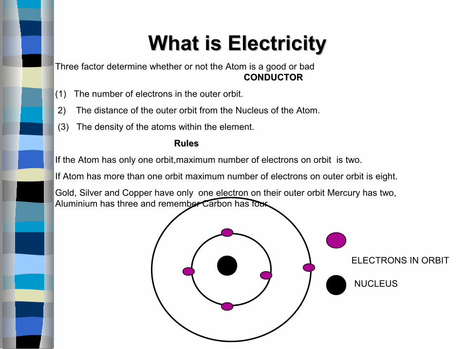
What is ElectricityWhat is ElectricityThree factor determine whether or not the Atom is a good or bad
CONDUCTORCONDUCTOR
(1) The number of electrons in the outer orbit.
2) The distance of the outer orbit from the Nucleus of the Atom.
(3) The density of the atoms within the element.
Rules Rules
If the Atom has only one orbit,maximum number of electrons on orbit is two.
If Atom has more than one orbit maximum number of electrons on outer orbit is eight.
Gold, Silver and Copper have only one electron on their outer orbit Mercury has two, Aluminium has three and remember Carbon has four.

ELECTRONS IN ORBIT
PROTONS IN NUCLEUSNUCLEUS
COPPER ATOM ( good Conductor)29 protons 29 electrons.
But only one loose electron On The outer orbit
CARBON ATOMCARBON ATOM. 4 ELECTRONS ON THE OUTER ORBIT (semi conductor)
What is ElectricityWhat is Electricity
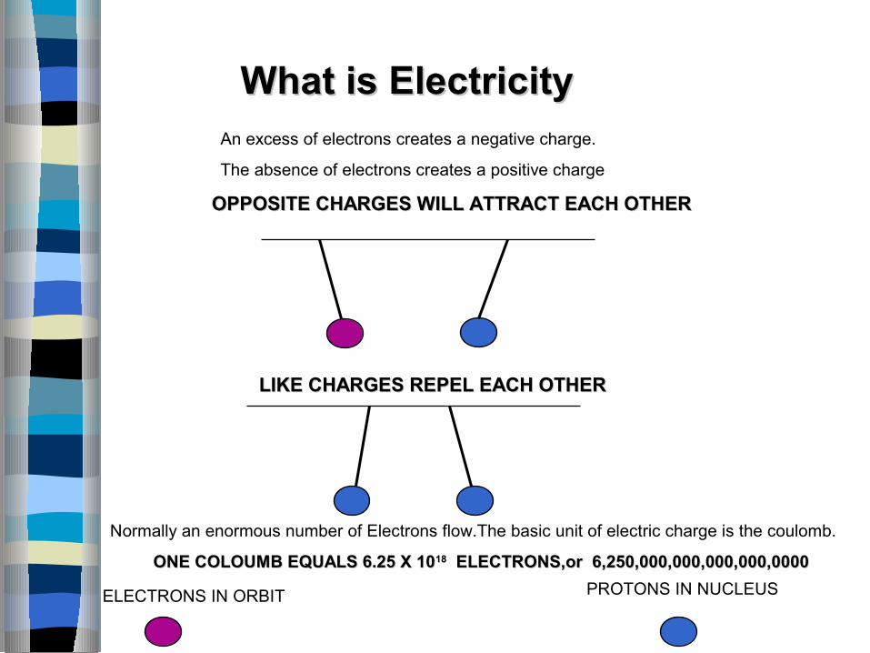
LIKE CHARGES REPEL EACH OTHERLIKE CHARGES REPEL EACH OTHER
What is ElectricityWhat is Electricity An excess of electrons creates a negative charge.
The absence of electrons creates a positive charge
OPPOSITE CHARGES WILL ATTRACT EACH OTHEROPPOSITE CHARGES WILL ATTRACT EACH OTHER
Normally an enormous number of Electrons flow.The basic unit of electric charge is the coulomb.
ONE COLOUMB EQUALS 6.25 X 10ONE COLOUMB EQUALS 6.25 X 101818 ELECTRONS,or 6,250,000,000,000,000,0000 ELECTRONS,or 6,250,000,000,000,000,0000
ELECTRONS IN ORBIT PROTONS IN NUCLEUS

Electron flow
Conventional flow
load
battery
switch
Anode\positive
battery post
What is ElectricityWhat is Electricity
+ -Cathode\negative

Electron flow
Conventional flow
load
battery
switch
Anode\positive
battery post
+ -
The loss of an electron by an atom makes it a positive ion, therefore it will attract an electron from a neighbouring atom,to again become balanced.
Basics of electricity
Electricity-
- There are variety of methods for producing electricity - Through chemical reaction in a battery.
- For large amount of electricity electromagnetic
generators are used.

Current -
- Flow of electron.
- Conventional current is in opposite direction.
- High voltage to low voltage.
- Unit of current is ampere.
- Current is measured by ammeter, Connected in
series.
- Polarity in DC
6
Basics of electricity-
Basics of electricity-
Potential - Ability to do work
Voltage - Potential difference.(work done in moving a unit +ve charge
from a point of lower to higher potential).
- Unit of voltage is volt (v).
- Measured by voltmeter,connected across source.
- Sources can be Battery,DC generator,alternator etc.
- Can be AC or DC.
- Polarity in DC
- Equivalent to two water tanks,connected by pipe water
flows.
8
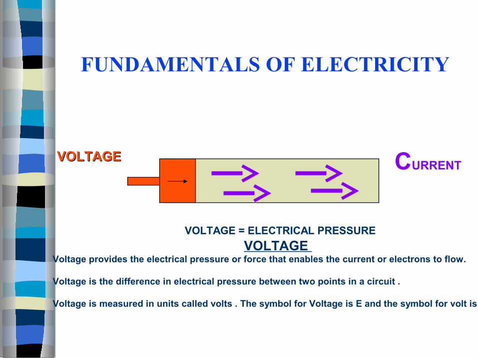
VOLTAGEVOLTAGE CURRENT
VOLTAGE = ELECTRICAL PRESSURE
FUNDAMENTALS OF ELECTRICITY
VOLTAGE Voltage provides the electrical pressure or force that enables the current or electrons to flow.
Voltage is the difference in electrical pressure between two points in a circuit .
Voltage is measured in units called volts . The symbol for Voltage is E and the symbol for volt is V.
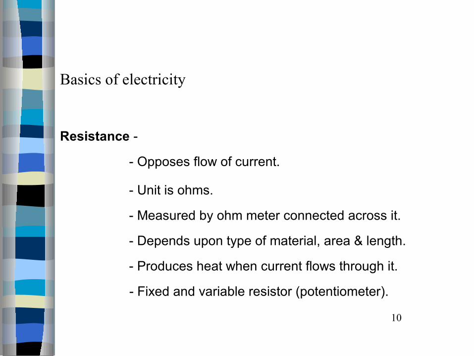
Basics of electricity
Resistance -
- Opposes flow of current.
- Unit is ohms.
- Measured by ohm meter connected across it.
- Depends upon type of material, area & length.
- Produces heat when current flows through it.
- Fixed and variable resistor (potentiometer).
10
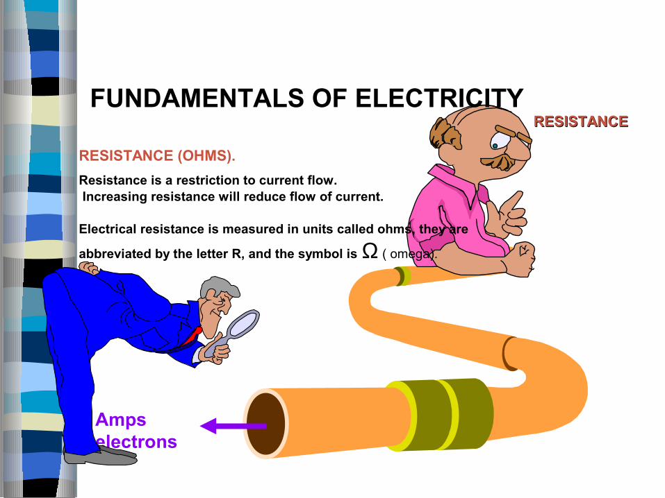
Amps electrons
RESISTANCE (OHMS).
Resistance is a restriction to current flow. Increasing resistance will reduce flow of current.
Electrical resistance is measured in units called ohms, they are
abbreviated by the letter R, and the symbol is Ω ( omega).
RESISTANCERESISTANCEFUNDAMENTALS OF ELECTRICITY
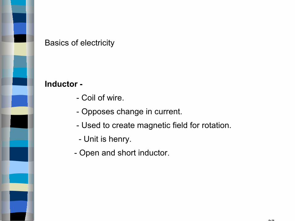
Basics of electricity
Inductor -
- Coil of wire.
- Opposes change in current.
- Used to create magnetic field for rotation.
- Unit is henry.
- Open and short inductor.
27
Basics of electricity
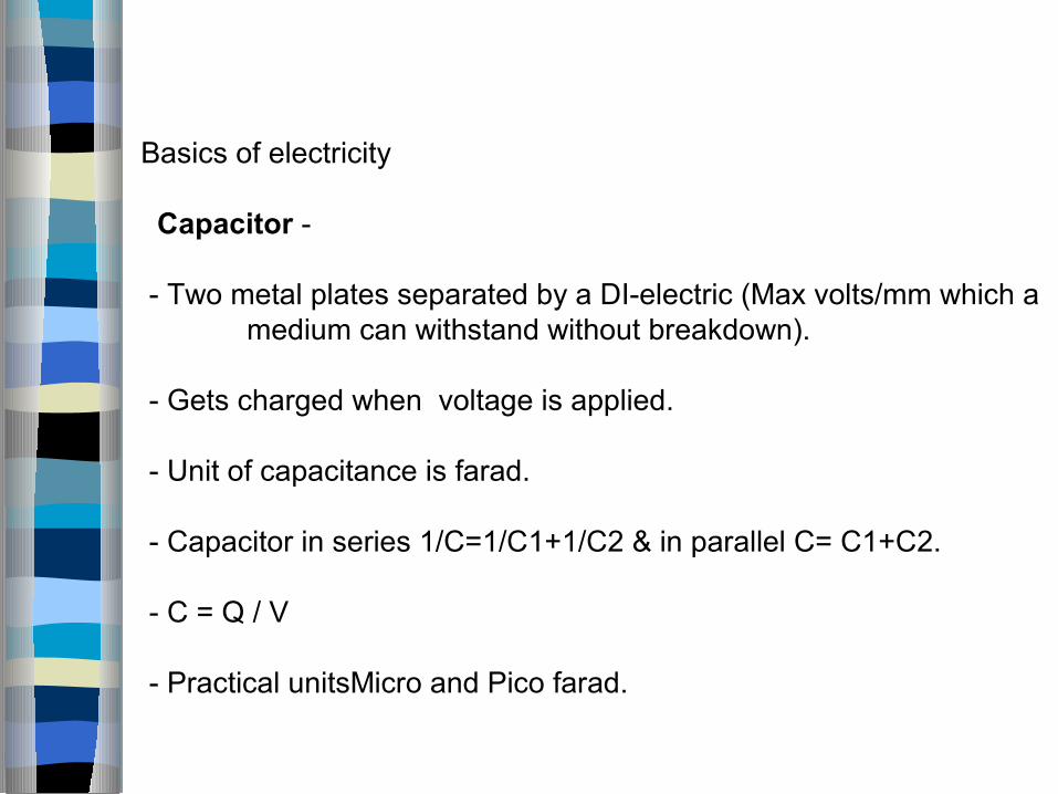
Capacitor -
- Two metal plates separated by a DI-electric (Max volts/mm which a medium can withstand without breakdown). - Gets charged when voltage is applied.
- Unit of capacitance is farad.
- Capacitor in series 1/C=1/C1+1/C2 & in parallel C= C1+C2.
- C = Q / V
- Practical unitsMicro and Pico farad.

Basics of electricity
Insulators and Conductors -Conductors -- Materials that have a low resistance to current flow are classified as conductors.- Copper and aluminium wires are conductors.- Conductors are used in electrical circuits to connect components to one another.- Conductors are wrapped in insulators to isolate from one another.Insulators -- Materials that have a high resistance to current flow are classified as Insulators.- Glass, rubber & dry air are insulators
13

Basics of electricity
Ohm’s law - Relation between three quantities learnt
V= I x R
I = V/ R
R = V / I
Where R = Resistance of circuit, in ohms.
V = Applied voltage, in volts.
I = Current, in amperes.

EE
II RR
EE
II R
EE E
I RR II RR
OHMS LAW
Ohms Law Pie Chart Resistance = Voltage over Current
Current = Voltage over Resistance voltage = Current times Resistance
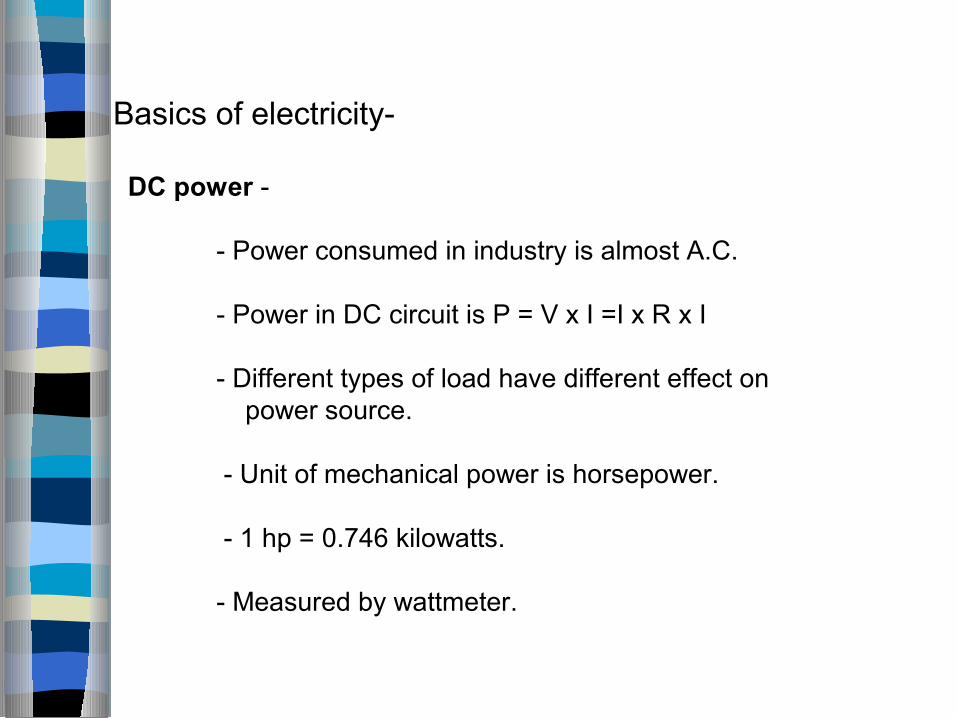
Basics of electricity-
DC power -
- Power consumed in industry is almost A.C.
- Power in DC circuit is P = V x I =I x R x I
- Different types of load have different effect on power source.
- Unit of mechanical power is horsepower.
- 1 hp = 0.746 kilowatts.
- Measured by wattmeter.
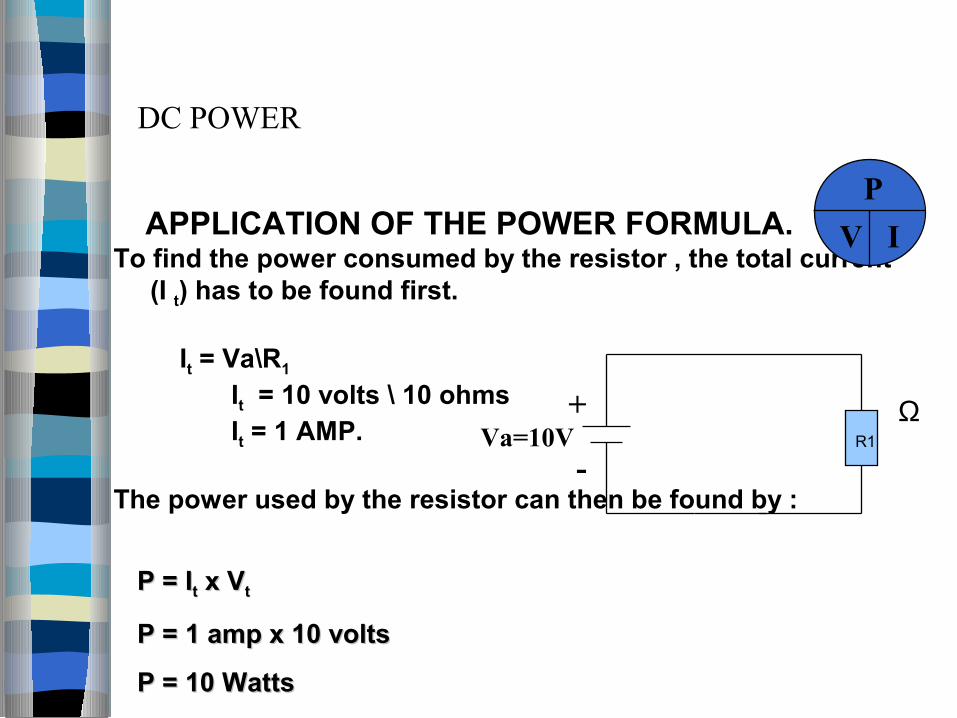
APPLICATION OF THE POWER FORMULA.To find the power consumed by the resistor , the total current (I t) has to be found first.
It = Va\R1
It = 10 volts \ 10 ohms It = 1 AMP.
The power used by the resistor can then be found by :
DC POWER
P
V I
+
-Va=10V
ΩR1
P = IP = Itt x V x Vtt
P = 1 amp x 10 voltsP = 1 amp x 10 volts
P = 10 WattsP = 10 Watts
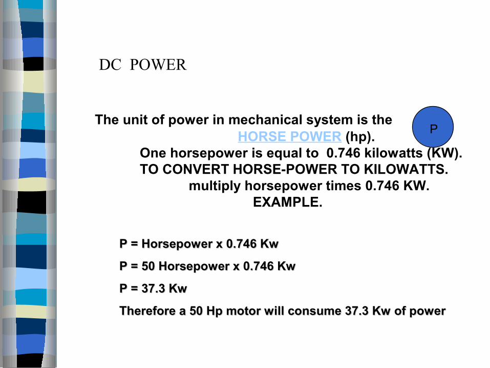
The unit of power in mechanical system is the
HORSE POWER (hp).One horsepower is equal to 0.746 kilowatts (KW).TO CONVERT HORSE-POWER TO KILOWATTS.
multiply horsepower times 0.746 KW. EXAMPLE.
P = Horsepower x 0.746 KwP = Horsepower x 0.746 Kw
P = 50 Horsepower x 0.746 KwP = 50 Horsepower x 0.746 Kw
P = 37.3 Kw P = 37.3 Kw
Therefore a 50 Hp motor will consume 37.3 Kw of power Therefore a 50 Hp motor will consume 37.3 Kw of power
P
DC POWER
Basics of electricity
AC Power-
- Alternating quantity is one which periodically passes through a definite cycle of changes.- In AC RMS values are used .- AC power is consumed by different types of load such as inductive , resistive & capacitive. - AC power is given by P= V x I x CosO- Symbol for AC source.- AC power is measured by Wattmeter.- Unit of power is Watts.
18

THE FOLLOWING TABLE SHOW SOME COMMON ELECTRICAL TERMS THEIR ABRIVIATION, UNITS OF MEASURE, SYMBOL
AND MEASURING INSTRUMENTS.
Term Abbreviation Unit Symbol Measuring Tool
Current I Ampere A Ammeter
Voltage E Volt V Voltmeter
Resistance R Ohm Ohmmeter
Power P Watt W Wattmeter
ELECTRICAL TERM

Basics of electricity
Series circuit -
- One path for current flow.
- Can have more than one load (e.g. resistance).
- Total load is sum of individual loads.
- Some voltage loss takes place across each load
and is called as voltage drop.
- Sum of voltage drops across each load is equal
to applied voltage.
- Current through each load is same.
- Open and short.
- Example - Chain of small bulbs.
20
OPEN AND SHORT CIRCUIT
R2
R3
R1
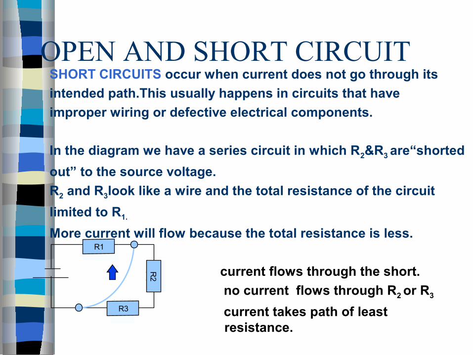
SHORT CIRCUITS occur when current does not go through its
intended path.This usually happens in circuits that have
improper wiring or defective electrical components.
In the diagram we have a series circuit in which R2&R3 are“shorted
out” to the source voltage.
R2 and R3look like a wire and the total resistance of the circuit
limited to R1.
More current will flow because the total resistance is less.
current flows through the short.
no current flows through R2 or R3
current takes path of least resistance.
OPEN AND SHORT CIRCUITS
+ R1
R2
R3
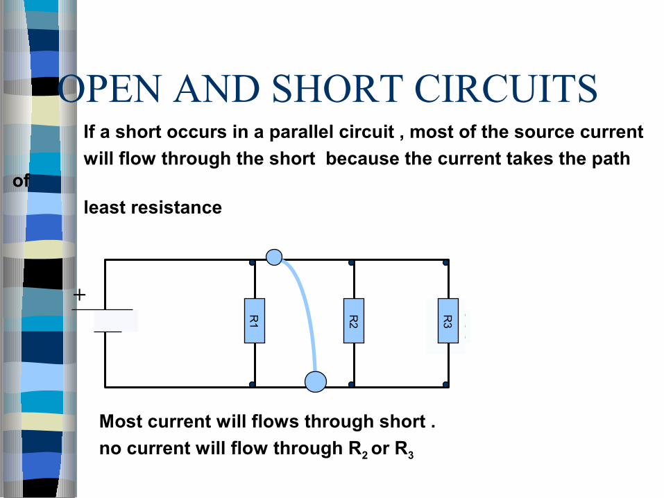
If a short occurs in a parallel circuit , most of the source current
will flow through the short because the current takes the path of
least resistance
Most current will flows through short .
no current will flow through R2 or R3
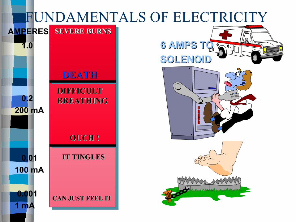
CAN JUST FEEL ITCAN JUST FEEL IT
DEATHDEATH
IT TINGLESIT TINGLES
OUCH !OUCH !
DIFFICULT DIFFICULT BREATHINGBREATHING
SEVERE BURNSSEVERE BURNSAMPERES
1.0 6 AMPS TO6 AMPS TO
SOLENOIDSOLENOID
0.2
200 mA
0.01
100 mA
0.001
1 mA
FUNDAMENTALS OF ELECTRICITY

DIGITAL MULTIMETER DESCRIPTION.DIGITAL MULTIMETER DESCRIPTION.
Measures Electrical Characteristics. Measures Multiple Types Of Electrical Characteristics with a
single device. Functions as a Ohmmeter,Ammeter and Voltmeter. Includes an AC, as well as DC Voltage range. Provides a Display “ Screen “. Includes option for an analog format.
The accuracy of the fluke meter is specified as of the reading + ( number of least significant digits.)
EG. Voltage dc

ROTARY SWITCH.
To turn the meter on , turn the rotary switch from the OFF position .
The meter performs a selftest , then starts taking readings.
DIGITAL MULTIMETER DESCRIPTIONDIGITAL MULTIMETER DESCRIPTION

VOLTAGE MEASUREMENT
Ranges
0 to1000 Volts dc
0 to 750 Volts ac
DIGITAL MULTIMETER DESCRIPTIONDIGITAL MULTIMETER DESCRIPTION
Measure in parallel across item to be measured
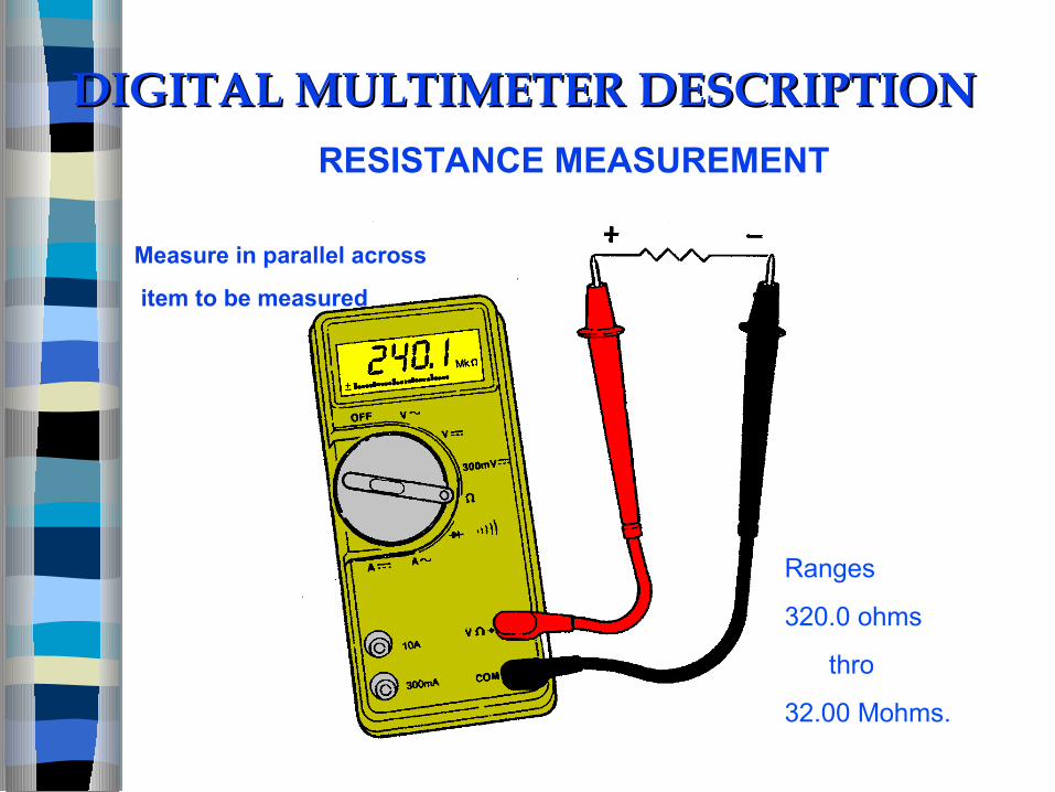
DIGITAL MULTIMETER DESCRIPTIONDIGITAL MULTIMETER DESCRIPTIONRESISTANCE MEASUREMENT
Measure in parallel across
item to be measured
Ranges
320.0 ohms
thro
32.00 Mohms.

CURRENT MEASUREMENT
Measure in series with
item to be measured
Ranges
AC. 320 mAmps &
10 Amps
DC. 320 mAmps &
10 Amps.

Range
2 Volts dc.
Continuity test.
Bleep while resistance is below 150 ohms
DIGITAL MULTIMETER DESCRIPTIONDIGITAL MULTIMETER DESCRIPTIONDIODE TEST
Measure in parallel across
item to be measured
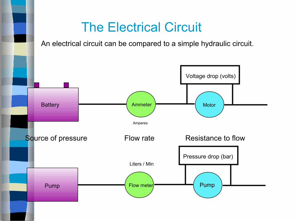
An electrical circuit can be compared to a simple hydraulic circuit.
Battery
Pump
Ammeter Motor
Voltage drop (volts)
Flow meter
Pressure drop (bar)
Source of pressure Flow rate Resistance to flow
Pump
Amperes
Liters / Min
The Electrical Circuit

Basics of electricity-
Types of loads - (Resistor,inductor& capacitor) Resistive load -
- In DC circuit (fig) the voltage and current waveforms are straight lines because voltage is constant. - In AC circuit with pure resistance,voltage and current are always in phase. - Power consumed in DC circuit is constant as voltage and current are constant. - An AC ckt. that has only resistance produces a positive power curve.
35

Basics of electricity-
Types of loads - (Resistor,inductor& capacitor) Resistive load -
- In DC circuit (fig) the voltage and current waveforms are straight lines because voltage is constant.
- In AC circuit with pure resistance,voltage and current are always in phase.
- Power consumed in DC circuit is constant as voltage and current are constant.
- An AC ckt. that has only resistance produces a positive power curve.
Basics of electricity
Inductive load -
- An inductor is a coil of wire. A common inductive
load is an electric motor.
- Current lag behind voltage by 900 since voltage
is max at 900 while current is zero.
- Produce both positive and negative power. These
powers are equal in amplitude so their sum will
equal to zero.
- The inductor does not use real power still generator
supply it with voltage and current .
- So efficiency is lowered.
37

Basics of electricity
Capacitive load-
- A capacitor opposes change in voltage.
- Current lead voltage by 900 since voltage across it
is zero and the current is maximum.
- Produce both positive and negative power. These
powers are equal in amplitude so their sum will
equal to zero.
- The capacitor does not use real power still generator
supply it with voltage and current .
- So efficiency is lowered. 39


![[] Basic Electrical Circuits](https://static.fdocuments.in/doc/165x107/55cf8cc45503462b138f9bb8/-basic-electrical-circuits.jpg)