Basic Networking Crash Course 2017 RVTEC Meeting · Basic Networking Crash Course 2017 RVTEC...
59
Basic Networking Crash Course 2017 RVTEC Meeting University of Minnesota Duluth, Large Lakes Observatory October 27 th - Duluth, Minnesota Britton Anderson, Office of Information Technology University of Alaska
Transcript of Basic Networking Crash Course 2017 RVTEC Meeting · Basic Networking Crash Course 2017 RVTEC...

Basic Networking Crash Course
2017 RVTEC Meeting
University of Minnesota Duluth, Large Lakes Observatory
October 27th - Duluth, Minnesota
Britton Anderson, Office of Information Technology University of Alaska

Objectives
• Describe basic networking components and operations
• Explain the fundamentals of network communication
• Define common networking terms • Analyze the OSI Model • Identify the functions of various network services • Describe functions and challenges of shipboard
networks • Overview of optimizing TCP throughput

An Overview of Computer Concepts
• Most of the devices you encounter when working with a network involve a computer
• Most obvious devices are workstations and network servers – These run operating systems such as Windows,
Linux, UNIX, and Mac OS • Also includes routers and switches
– These are specialized computers used to move data from computer to computer and network to network

Network Components
• Hardware components – Network interface card—A NIC is module that's built in to the
motherboard, or plugged into the motherboard’s expansion slot and provides a connection between the computer and the network.
– Network medium—A cable that plugs into the NIC and makes the connection between a computer and the rest of the network. Network media can also be the air waves, as in wireless networks.
– Interconnecting—Interconnecting devices allow two or more computers to communicate on the network without having to be connected directly to one another.

Fundamentals of Network Communication
• A computer network consists of two or more computers connected by some kind of transmission medium, such as a cable or air waves.
• In order to access the Internet, a computer has to be able to connect to a network.

A Typical Home Network
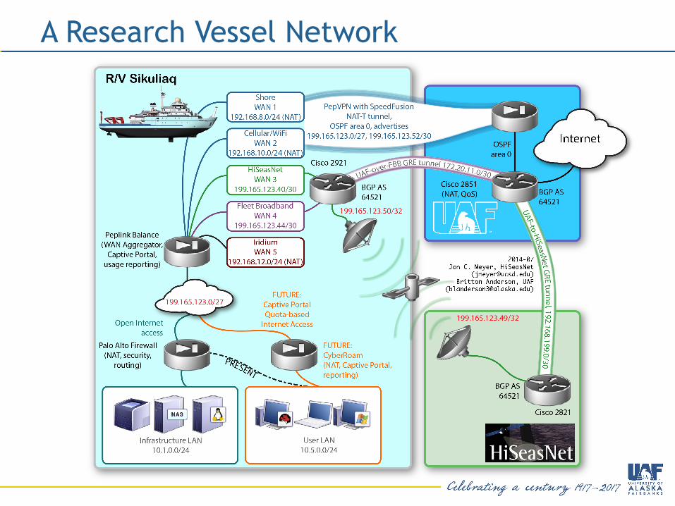
A Research Vessel Network

Network Components
• Software Components – Network clients and servers—Network client software
requests information that's stored on another network computer or device. Network server software allows a computer to share its resources by fielding resource requests generated by network clients.
– Protocols—Network protocols define the rules and formats a computer must use when sending information across the network. Think of it as a language that all devices on a network understand.
– Network interface—The network access interface that transmits and receives data from the network medium
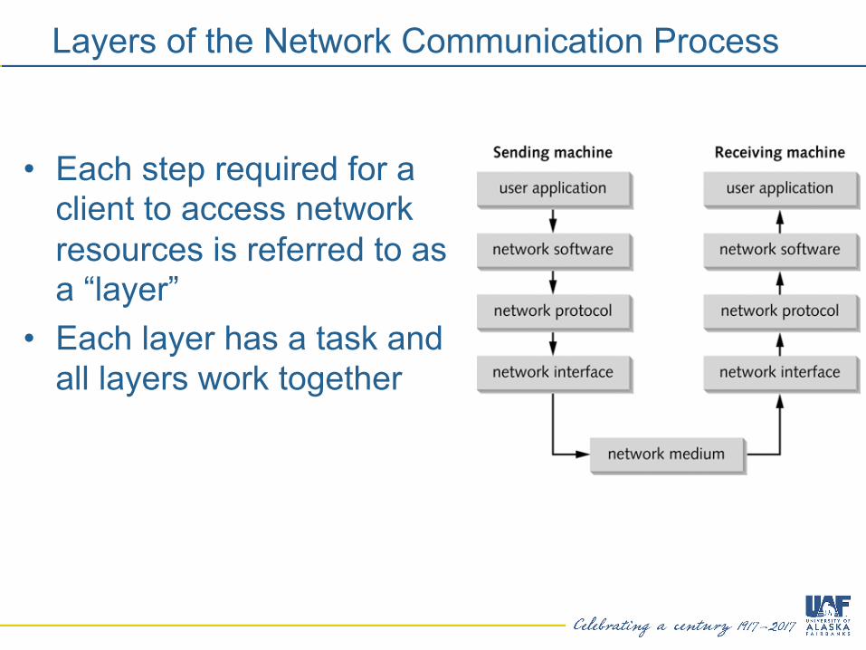
Layers of the Network Communication Process
• Each step required for a client to access network resources is referred to as a “layer”
• Each layer has a task and all layers work together

Network Terms
• Every profession has its own language and acronyms
• Need to know the language of networks to be able to properly communicate needs and issues off ship.

LANs, Internetworks, WANs
• Local area network (LAN) – small network, limited to a single collection of machines and connected by one or more interconnecting devices in a small geographic area
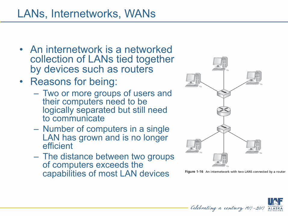
LANs, Internetworks, WANs
• An internetwork is a networked collection of LANs tied together by devices such as routers
• Reasons for being: – Two or more groups of users and
their computers need to be logically separated but still need to communicate
– Number of computers in a single LAN has grown and is no longer efficient
– The distance between two groups of computers exceeds the capabilities of most LAN devices

How Two Computers Communicate
• TCP/IP is the most common protocol (language) used on networks
• TCP/IP uses 2 addresses to identify devices on a network – Logical address (called IP address) – Physical address (called MAC address)
• Just as a mail carrier needs an address to deliver mail, TCP/IP needs an address in order to deliver data to the correct device on a network
• Think of the Logical address as a zip code and the Physical address as a street address
Packets and Frames
• Computers transfer information across networks in shorts bursts of about 1500 bytes of data
• Data is transferred in this way for a number of reasons: – The pause between bursts might be necessary to allow other
computers to transfer data during pauses – The pause allows the receiving computer to process received
data, such as writing it to disk – The pause allows the receiving computer to receive data from
other computers at the same time – The pause gives the sending computer an opportunity to receive
data from other computers and to perform other processing tasks
– If an error occurs during transmission of a large file, only the chunks of data involved in the error have to be sent again, not the entire file

Packets
• Chunks of data sent across the network are usually called packets or frames, with packets being the more well-known term
• Frames are packets with source and destination MAC addresses, and error checking added to it
• Using the USPS analogy, you can look at a packet as an envelope containing the data that has a street address on it.

Frames
• A frame is outside a packet with the source and destination MAC addresses added to it
• The frame is built with the MAC addresses on the beginning and an error-checking code on the end. In between them is the packet
• A frame is like the mail carrier moving your envelope and your letter from place to place
• The process of adding IP addresses and MAC addresses to packets and frames to chunks of data is called encapsulation
• Information added to the front of the data is called a header and information added to the end is called a trailer

Communication Between Two Computers
1. A user at Comp A types ping 10.1.1.2 at a command prompt
2. The network software creates a ping message
3. The network protocol packages the message by adding IP address of sending and destination computers and acquires the destination computer’s MAC address
4. The network interface software adds MAC addresses of sending and destination computers and sends the message
5. Comp B receives message, verifies that the addresses are correct and then sends a reply to Comp A using Steps 2 – 4

Clients and Servers
• A client can be a workstation running a client OS or it can also refer to the network software on a computer that requests network resources from a server
• The word “client” is usually used in these three contexts: – Client operating system: The OS installed on a computer – Client computer: Primary role is to run user applications
and access network resources – Client software: The software that requests network
resources from server software running on another computer

Clients and Servers
• A computer becomes a server when software is installed on it that provides a network service to client computers
• The term “server” is also used in three contexts: – Server operating system: When the OS installed on a
computer is designed mainly to share network resources and provide other network services
– Server computer: When a computer’s primary role in the network is to give client computers access to network resources and services
– Server software: Responds to requests for network resources from client software running on another computer

Network Models
• A network model is a framework to conceptually divide network functions progressively in a logical reference.
• Two major models exist – TCP/IP Model Often referred to as the DOD model
since it was originally designed for them – OSI Network Model developed by the International
Standards Organization as a standard called the Open Systems Interconnection (OSI) reference model.

Model Comparison
Layer 1 – The Physical Layer
• In networking, data is transmitted in bits – A pulse of 5 volts of electricity can represent a
1 bit and a pulse of 0 volts can represent a 0 bit
– With fiber-optic cable, a 1 bit is represented by the presence of light and a 0 bit by the absence of light
– WiFi transmits and receives radio wave pulses in either 2.4GHz or 5GHz frequencies.
• A “byte” is a collection of 8 bits

Layer 1 – Media
• Layer 1 is primarily known for the physical network cabling. While copper and fiber are the de facto standards, different types exist for each.
• Fiber optics – where the differences matter – Multimode
• 62.5um-–FDDI/OM1, 50um--OM2, OM3, OM4 – Singlemode
• OS1, OS2
• UTP/STP Copper Cabling – CAT5/5e/6/6A/7
• Coax

Layer 1 – Devices
• Layer 1 devices are purely electrical • Repeaters
– In line devices that repeat signals to overcome distance limitations.
– Versions exists for all types of media • Hubs
– Like a repeater, it repeats signals received from one source, but to all other connected destinations
• Network Interface Cards (NICs) – Also partially a layer 2 device

Layer 1 - Troubleshooting
• Link testers – Fluke Networks – NetScout – NetTool.io

Layer 2 – Data Link
• Standardized transmission/reception – Ethernet – MPLS – Frame Relay
• Standardizes hardware media access control (MAC) addresses – 48 bit addresses, consisting of a 24-bit Organizational Unit
Identifier (OUI), and a 24-bit unique address. – OUI identifies the originating manufacturer of the NIC.
• Error detection and correction • Spanning Tree
Layer 2 - Devices
• Switches – Maintains an internal table identifying MAC addresses
through corresponding ports. – Uses the Source/Destination MAC address in the frame to
make intelligent decisions to move frames. – Faster than routing, not as scalable. – Trunks/uplinks will commonly see many MAC addresses – Can segment networks into Virtual LANs (VLANs).
• Network Interface Cards (NICs) – Converts bits and data into signals for transmission on
network media. Converts signals back to bits for reception.

Layer 2 - Troubleshooting
• View the MAC table

Layer 2 - Troubleshooting
• View Spanning Tree

Layer 3 - Network
• The most complex layer in the OSI model. – Also one that presents the most problem areas.
• TCP – The most common protocol suite used in networking. UDP – Very prevalent in streaming data. – IPv4 – Still most common addressing suite in use, however
exhausted. 32-bit based addresses • 4.3 billion addresses globally
– IPv6 – Standardized for nearly two decades, not seeing wide adoption, but rollout gaining stream. 128-bit
• 3.4e38 addresses globally

Layer 3 – IP Addressing
• IPv4 – 32-bit addresses, dotted decimal octets. Most common. – Subnet mask delimiter segments IP networks. – Ex. Subnet mask of 255.255.255.0 and an IP address of
10.11.12.13 segments the first three octets for the network ID, and the last octet for hosts in the network.
– Private reserved IP ranges to preserve exhausted public ranges
• IPv6 – 128-bit addresses in 16-bit hexadecimal segments
• Subnet mask represented with the address. • Trailing zeros summarized with :: • Ex 2607:f318::/32 ==
2607:f318:0000:0000:0000:0000:0000:0000/32

Layer 3 - IP Addressing
• DHCP – Dynamic Host Control Protocol – Allows for automated IPv4 configuration to hosts
on your network. – Provisions IP address, subnet mask, default
gateway, DNS servers at a minimum. – Can also allow DNS registration, NTP
configuration, limited automated configuration parameters.
– DHCPv6 exists for IPv6 control • SLAAC – Stateless Automated Address
Configuration – Automated IPv6

Layer 3 - ARP
• Address resolution protocol binds IP addresses to MAC addresses.
• As a packet reaches a subnet, a broadcast message is sent to all connected hosts to discover what MAC address has the destination IP address.
• If the IP address does not match the network as designated by the subnet mask, an ARP request is sent for the address of the default gateway.
• ARP entries are stored in a cache table so broadcasts don’t have to continually be sent out for each frame.

Layer 3 – ARP Table
• Router – show ip arp
• Computer – arp -an

Layer 3 – Network Address Translation
• Private IPv4 ranges to preserve exhausted public IP space—RFC 1918 – 10.0.0.0/8 = 16.78 Million IP addresses – 172.16.0.0/12 = 1.04 Million IP addresses – 192.168.0.0/16 = 65,536 IP addresses
• Allows firewalls to associate a public IP to a private IP as needed – 1:1 – Host (Private IP) <> Firewall <> Public IP <>
Internet – As more traffic becomes internet dependant,
NAT becomes less useful as 1:1 relationship uses similar resources.
Layer 3 – Domain Name Service
• Domain Name Service (DNS) is a basic fundamental necessity of every day life.
• Brings accessibility by allowing internet navigation using text-based names (domains)
• Larger trusted structure worldwide indexes all names.
• DNS servers are responsible for translating domain names into IP addresses – First thing to occur when navigating to any
website

Layer 3 - Routing
• Makes up the internet – responsible for ensuring data moves through effective paths to its destination.
• Several standard routing protocols exist to automate the provisioning of network routes. – Interior Gateway Protocol (IGP)
• Open Shortest Path First (OSPF) • Enhanced Interior Gateway Routing Protocol (EIGRP) • Routing Information Protocol (RIP/RIPv2) • Primarily what we ship-going folks are concerned with
– Exterior Gateway Protocol (EGP) • Used to advertise routes to the public internet. Can
not advertise private IP addresses externally. • Border Gateway Protocol (BGP)

Layer 3 - Hardware
• Routers – Specialized hardware with few ports – Designed to table large route tables and
direct traffic efficiently – Peplink Balance appliance is a special type of
router with proprietary functions.
• Multilayer (Layer 3) Switching – Switches with beefier memory and cpu to
both switch and route traffic. – Designed for specific functions in a small
environment, like a ship!

Layer 3 - Routing
• Routing Table

Layer 3 - Troubleshooting
• Ping

Layer 3 - Troubleshooting
• Traceroute

Layer 3 - Troubleshooting
• nslookup

Layer 3 - Troubleshooting
• Host

OSI Model Recap
Layer 4 - Transport
• Where applications become identified – based on port numbers
• Standard set of port numbers for well-known applications (0-1024 reserved as standards) – TCP/22 – SSH – TCP/80 – HTTP – TCP/443 – HTTPS – UDP/53 – DNS – Many many many more (and many more after that)
• 65,535 ports per IP address • IP address and port together is a socket

Layer 4 - Transport
• Firewalls - application identification – Basis for securing networks to allow specific
applications in/out specific networks. – Allows for application specific rules to deny certain
applications but not others while allowing others. – Next-gen firewalls (NGFW) use packet inspection to
identify applications’ traffic pattern signatures and can identify those using non-standard ports.

Layer 4 – Port Address Translation
• Supplants the Network Address Translation function at Layer 3 to use ports to translate many IP addresses to one. – Common in home networking. – Only allows one inside server to be reachable on a given
port due to port forwarding. – Best at conserving public IP addresses when many hosts
access internet resources - most common on ships. • Host (rhp)<>Router<>FW<>internet host(dst p) • Firewall translates the rhp to another rhp
– Firewall tracks the connection state to forward outside port to inside port.

Layer 4 – PAT Example
Source: Wikibooks

Layers 5, 6 & 7
• Layer 5 – Session – Ensures both TCP sessions and any system or user network
sessions (ex logging into your bank) are timed out appropriately.
– Where port numbers are originated and synchronized for source and destination to Transport layer.
• Layer 6 – Presentation – Where data is collected and prepared for the application.
Also where encryption/decryption happens
• Layer 7 – Application – This pptx presentation file displayed in front of you.

OSI Model Recap
7. Application 6. Presentation 5. Session 4. Transport 3. Network 2. Data Link 1. Physical
7. Acumen 6. Palin’s 5. Sarah 4. Test 3. Not 2. Do 1. Please
7. At 6. Present 5. Some 4. Teachers 3. Needs 2. Dr. 1. Phil

Bandwidth Delay Product
• TCP is the original protocol of the internet as built in the late 80s-early 90s. – Not particularly efficient with today’s workloads or
today’s bandwidth. – TCP receive window (RWIN) scales via Slow Start
• Scaling occurs slowly, and latency fluctuations (jitter) often cause it to restart.
• Results in single flows crawling over highly latent and fluctuating links.

Bandwidth Delay Product
• The BDP is a formula that can both determine maximum possible throughput given latency and loss, as well as unscaled RWIN values to reach desired throughput. – Bandwidth (Kbps) * Latency (ms) = RWIN (b) / 8 =
RWIN (B) – For example: 2000Kbps * 500ms = 1,000,000 / 8 =
125,000 bytes = 122.07KB RWIN -> 128KB RWIN

Congestion Window
• Sender controlled • Window managed by congestion algorithm • Input is varied by system and algorithm

Initial Congestion Window
• How much data to send before expecting to see acknowledgements. – Basis of the bandwidth delay product – Coordinated values with the TCP RWIN on the
receiver end – RWIN and CWIN values should be set on both sides
for optimum performance.

Impact of Loss

Retransmission Timers
• Input as to when congestion control considers a packet lost. – Too low: Retransmit lots of things possibly for no
reason – Too high: Connections sit for a while timers expire
for data to come back
Considerations
• CWIN/RWIN are critical to tune over high latency links like satellites for best performance. – CWIN values should be slightly less than BDP – RWIN values should be slightly higher
• Consider maximum average latency to maintain speeds.
• Optimize retransmission timers if necessary to eliminate fake loss. – Loss should not be expected, but can be prepared
for.

Conclusion
Questions?

Thank You!