Basic Hydraulics and Pump Applications In Wastewater · Pump Types used in Wastewater ... The...
92
Basic Hydraulics and Pump Applications In Wastewater 9/24/2015
Transcript of Basic Hydraulics and Pump Applications In Wastewater · Pump Types used in Wastewater ... The...
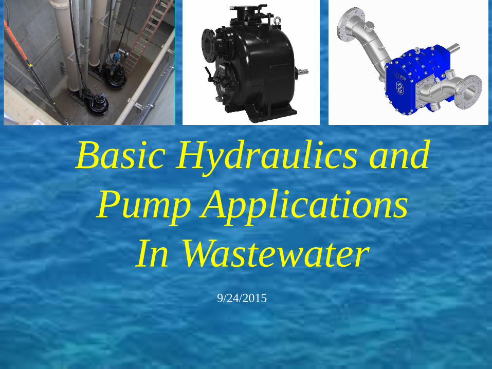
Basic Hydraulics and
Pump Applications
In Wastewater 9/24/2015

John Rogers EBARA International Corporation
Rock Hill, SC
Gary Rookstool, P.E. Winschel Environmental, LLC
Buchanan, VA
Matt Winschel, P.E. Winschel Environmental, LLC
Glen Allen, VA
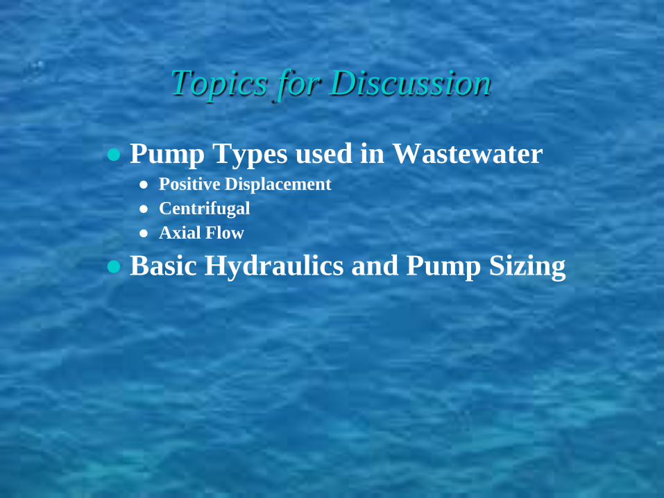
Topics for Discussion
● Pump Types used in Wastewater ● Positive Displacement
● Centrifugal
● Axial Flow
● Basic Hydraulics and Pump Sizing
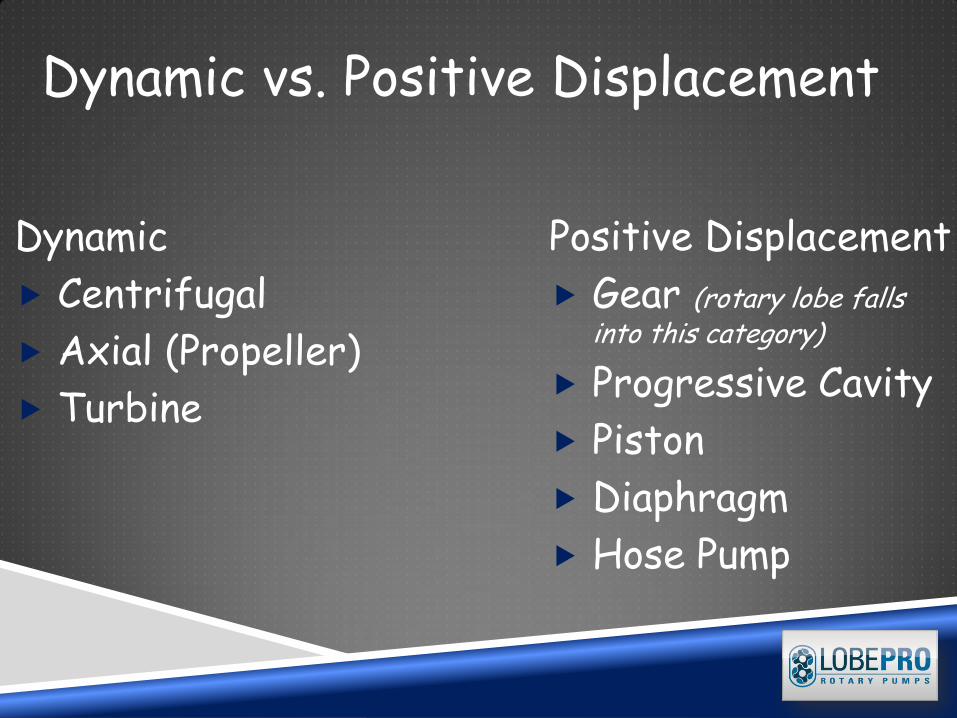
Dynamic
Centrifugal
Axial (Propeller)
Turbine
Positive Displacement
Gear (rotary lobe falls into this category)
Progressive Cavity
Piston
Diaphragm
Hose Pump
Dynamic vs. Positive Displacement
Reciprocating Rotary
Diaphragms Pistons Plungers

Lobes Screws
Peristalsis (gets its name from the muscular action of the human digestive tract.)
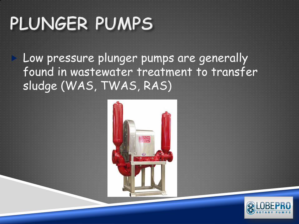
Low pressure plunger pumps are generally found in wastewater treatment to transfer sludge (WAS, TWAS, RAS)
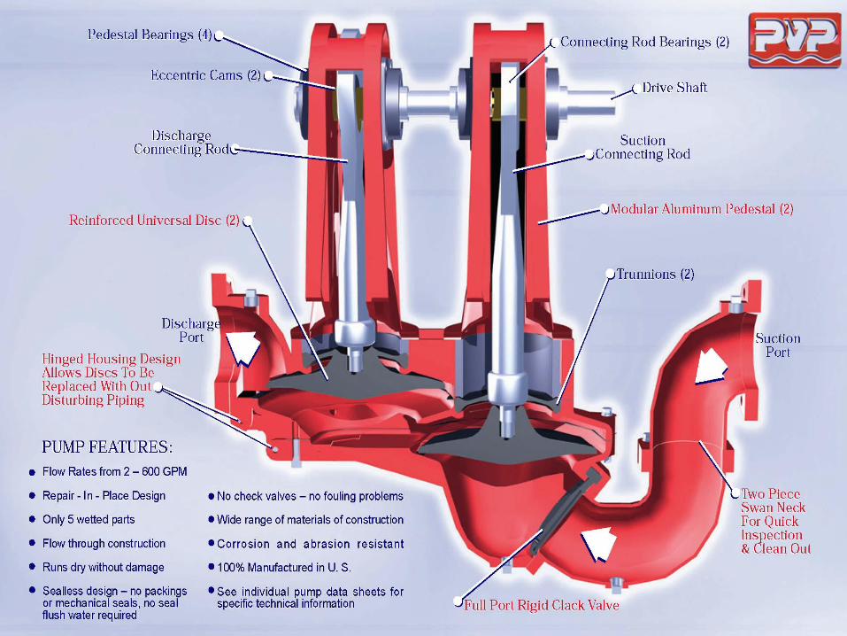
DIAPHRAGM PUMP
A diaphragm pump is a positive displacement pump that uses a combination of the reciprocating action of a rubber, thermoplastic or teflon diaphragm and suitable non-return check valves to pump a fluid. Sometimes this type of pump is also called a membrane pump.
CHARACTERISTICS
These pumps can handle sludges and slurries with a good amount of grit and smaller solids content.
Have good dry running characteristics.
Are low-shear pumps.
Can be used to make artificial hearts.
Have good self priming capabilities.
CHARACTERISTICS CONT.
Have good self priming capabilities Can handle highly viscous liquids Are available for industrial, chemical and
hygienic applications Cause a pulsating flow that may cause water
hammer (Water hammer is a pressure surge or wave caused when a fluid in motion is forced to stop or change direction suddenly)
Usually have limited capacities
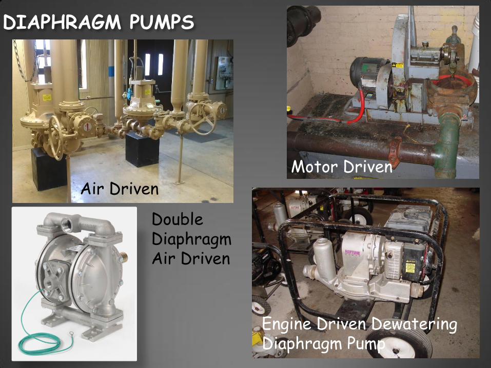
DIAPHRAGM PUMPS
Air Driven Motor Driven
Double Diaphragm Air Driven
Engine Driven Dewatering Diaphragm Pump
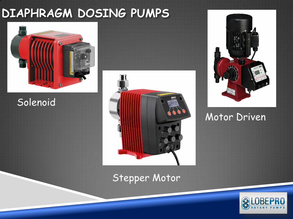
DIAPHRAGM DOSING PUMPS
Motor Driven
Solenoid
Stepper Motor
Gary
Typewritten Text
Photos Courtesy Lutz-JESCO
PERISTALTIC PUMP/HOSE PUMP
A peristaltic pump, or roller pump, is a type of positive displacement pump used for pumping a variety of fluids. The fluid is contained within a flexible tube fitted inside a circular pump casing (though linear peristaltic pumps have been made). A rotor with a number of "rollers", "shoes" or "wipers" attached to the external circumference compresses the flexible tube. As the rotor turns, the part of tube under compression closes (or "occludes") thus forcing the fluid to be pumped to move through the tube. Additionally, as the tube opens to its natural state after the passing of the cam ("restitution" or "resilience") fluid flow is induced to the pump.
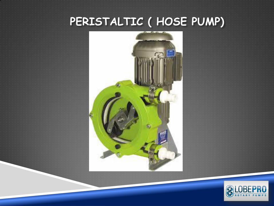
PERISTALTIC ( HOSE PUMP)
Gary
Typewritten Text
Photo Courtesy FLOMOTION SYSTEMS
Gary
Typewritten Text
Gary
Typewritten Text
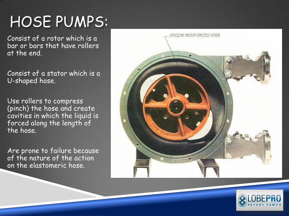
HOSE PUMPS: Consist of a rotor which is a bar or bars that have rollers at the end.
Consist of a stator which is a U-shaped hose.
Use rollers to compress (pinch) the hose and create cavities in which the liquid is forced along the length of the hose.
Are prone to failure because of the nature of the action on the elastomeric hose.
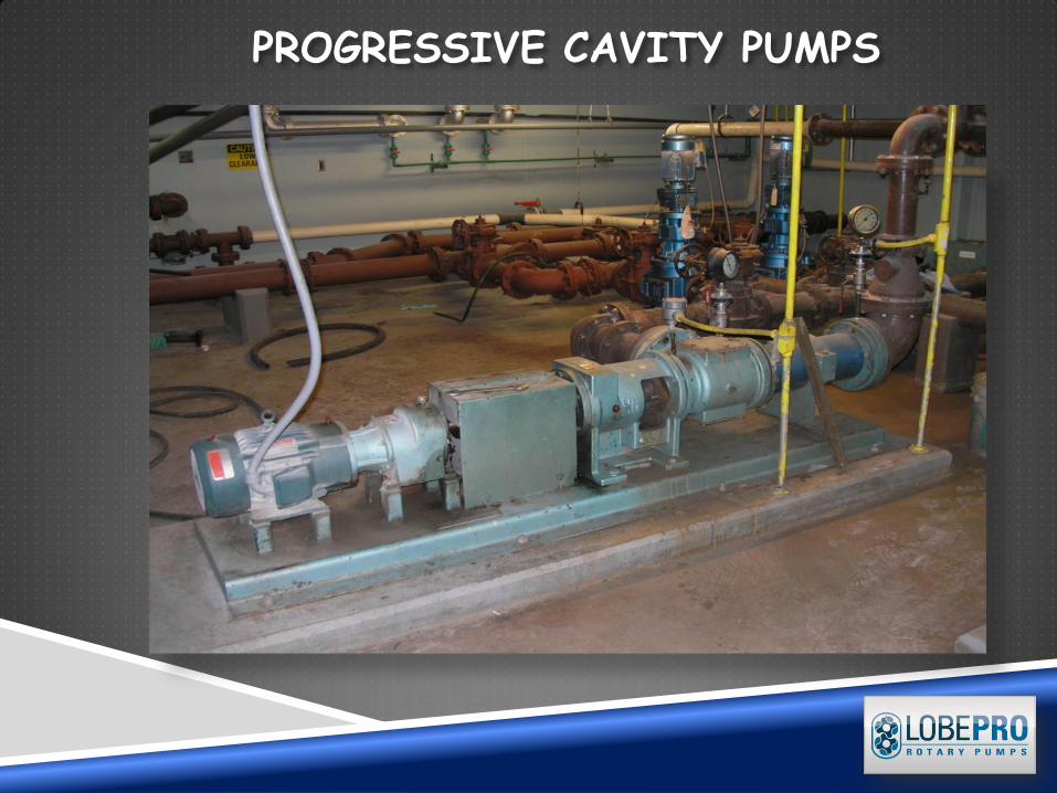
PROGRESSIVE CAVITY PUMPS
PROGRESSIVE CAVITY PUMPS
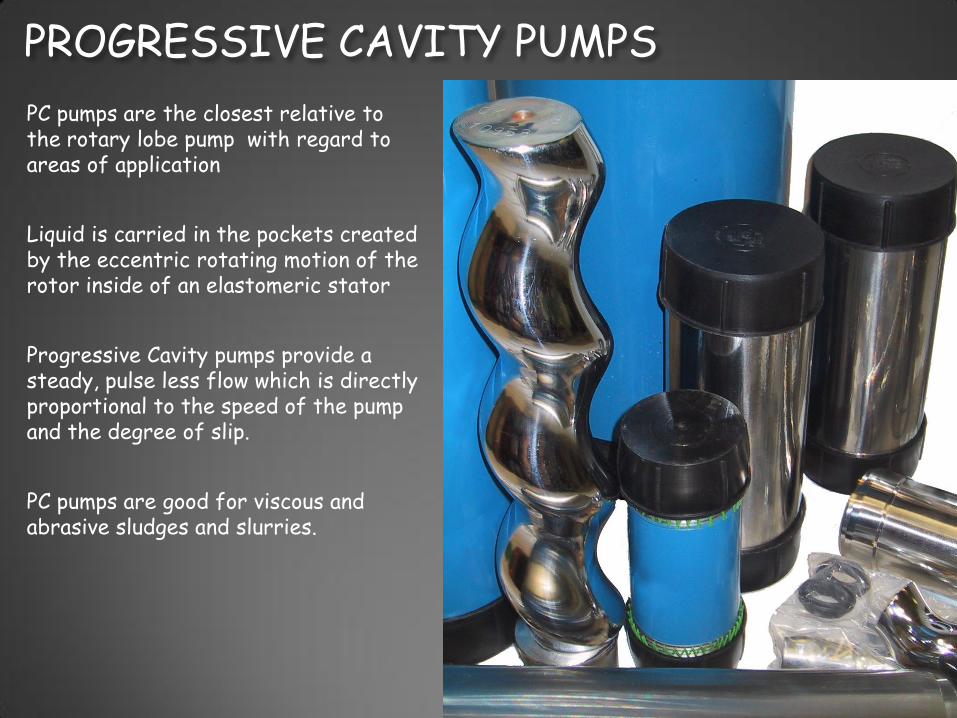
PC pumps are the closest relative to the rotary lobe pump with regard to areas of application
Liquid is carried in the pockets created by the eccentric rotating motion of the rotor inside of an elastomeric stator
Progressive Cavity pumps provide a steady, pulse less flow which is directly proportional to the speed of the pump and the degree of slip.
PC pumps are good for viscous and abrasive sludges and slurries.

How Lobe Pumps Work
Lobe pumps are similar to external gear pumps in operation in that fluid flows around the interior of the casing. Unlike external gear pumps, however, the lobes do not make contact. Lobe contact is prevented by external timing gears located in the gearbox. Pump shaft support bearings are located in the gearbox, and since the bearings are out of the pumped liquid, pressure is limited by bearing location and shaft deflection.
ROTARY LOBE PUMPS
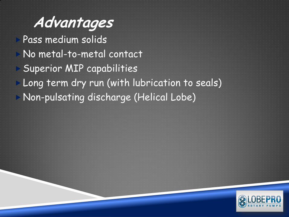
Advantages Pass medium solids
No metal-to-metal contact
Superior MIP capabilities
Long term dry run (with lubrication to seals)
Non-pulsating discharge (Helical Lobe)
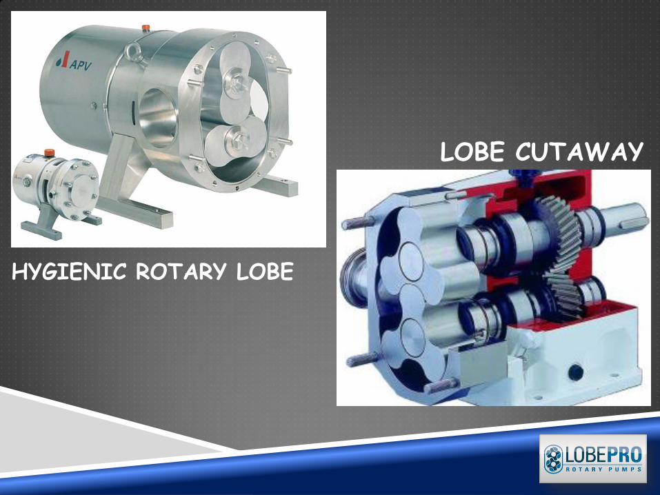
HYGIENIC ROTARY LOBE
LOBE CUTAWAY
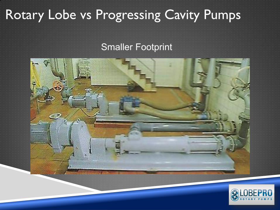
Rotary Lobe vs Progressing Cavity Pumps
Smaller Footprint

EBARA Fluid Handling | pumpsebara.com
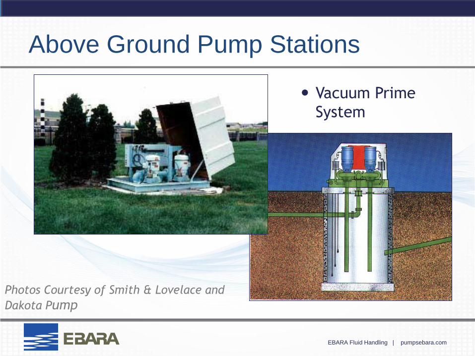
Above Ground Pump Stations
Vacuum Prime
System
Photos Courtesy of Smith & Lovelace and
Dakota Pump
EBARA Fluid Handling | pumpsebara.com
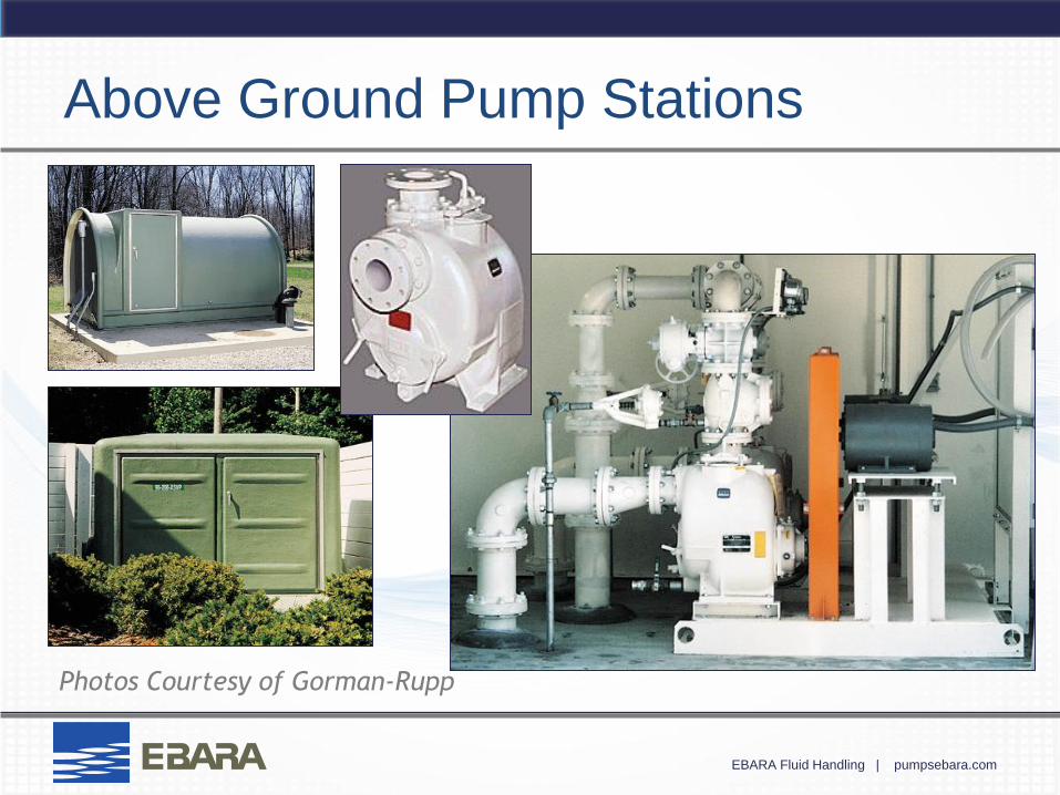
Above Ground Pump Stations
Photos Courtesy of Gorman-Rupp
EBARA Fluid Handling | pumpsebara.com
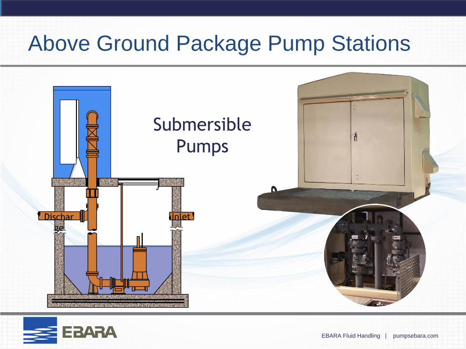
Above Ground Package Pump Stations
Inlet Dischar
ge
Submersible
Pumps
EBARA Fluid Handling | pumpsebara.com
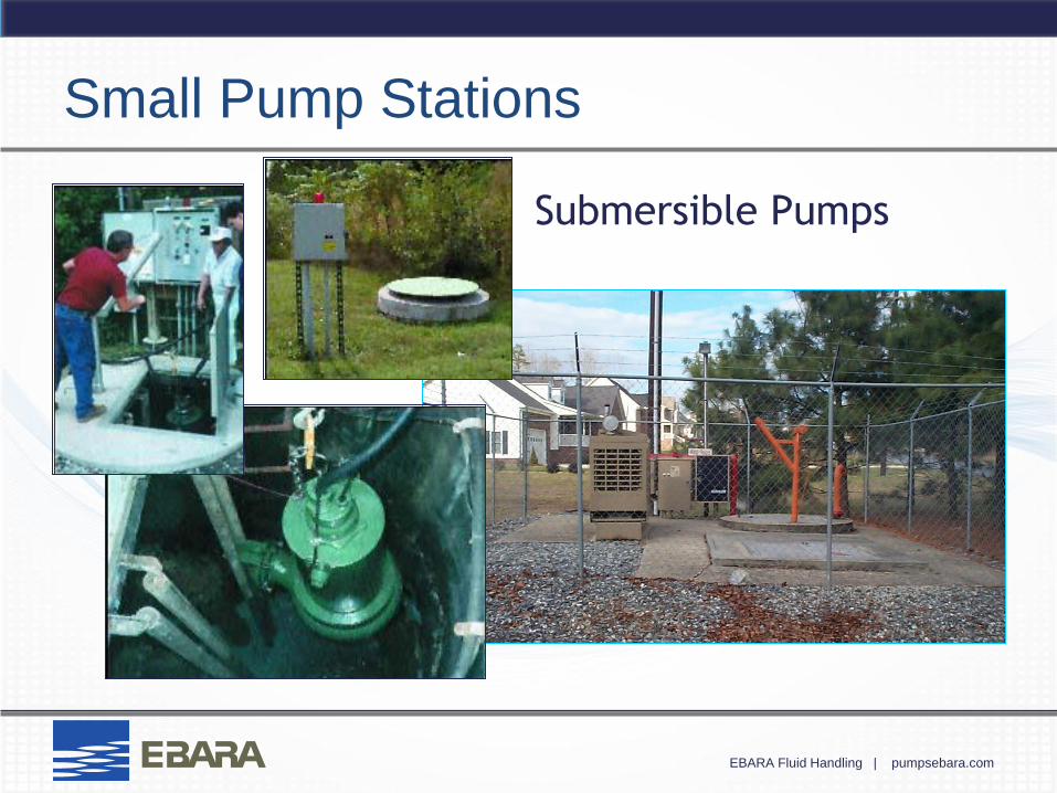
Small Pump Stations
Submersible Pumps
EBARA Fluid Handling | pumpsebara.com
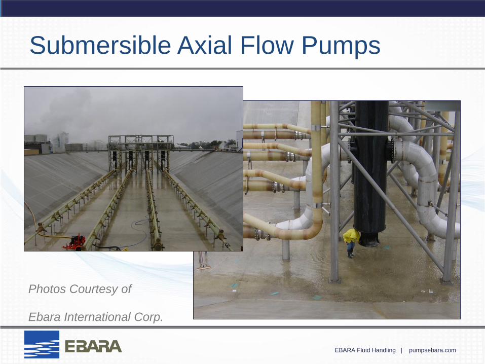
Submersible Axial Flow Pumps
Photos Courtesy of
Ebara International Corp.
EBARA Fluid Handling | pumpsebara.com
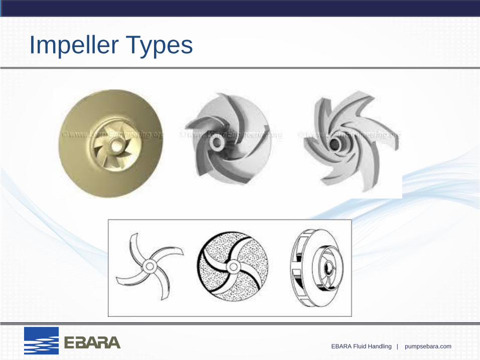
Impeller Types
Gary
Typewritten Text
Gary
Typewritten Text
Gary
Typewritten Text
Gary
Typewritten Text
Gary
Typewritten Text
Gary
Typewritten Text
Gary
Typewritten Text
Gary
Typewritten Text
Gary
Typewritten Text
Gary
Typewritten Text
Gary
Typewritten Text
ENCLOSED
Gary
Typewritten Text
Gary
Typewritten Text
Gary
Typewritten Text
SEMI OPEN
Gary
Typewritten Text
Gary
Typewritten Text
Gary
Typewritten Text
VORTEX
Gary
Typewritten Text
EBARA Fluid Handling | pumpsebara.com
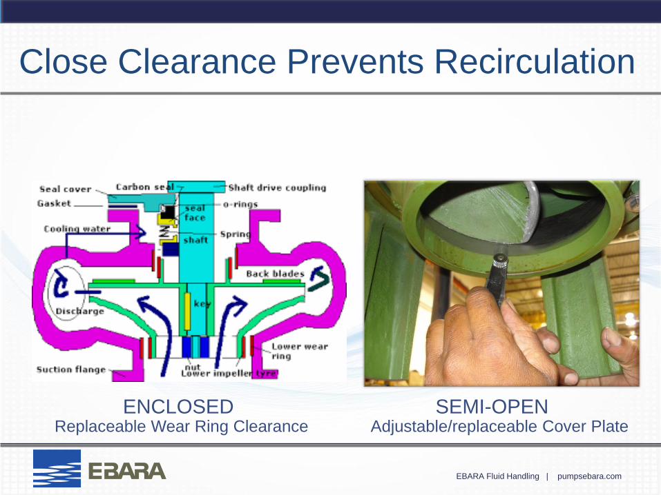
Close Clearance Prevents Recirculation
ENCLOSED SEMI-OPEN Replaceable Wear Ring Clearance Adjustable/replaceable Cover Plate

EBARA Fluid Handling | pumpsebara.com
Vortex (Recessed Impeller) Pumps
Gary
Typewritten Text
Gary
Typewritten Text
Gary
Typewritten Text

EBARA Fluid Handling | pumpsebara.com
EBARA
Submersible Pump
Installations
EBARA Fluid Handling | pumpsebara.com
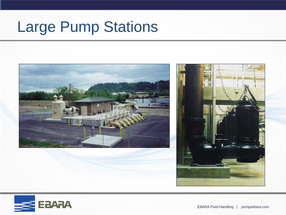
Large Pump Stations
EBARA Fluid Handling | pumpsebara.com
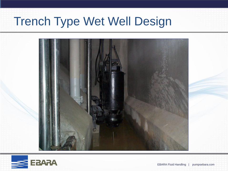
Trench Type Wet Well Design
EBARA Fluid Handling | pumpsebara.com
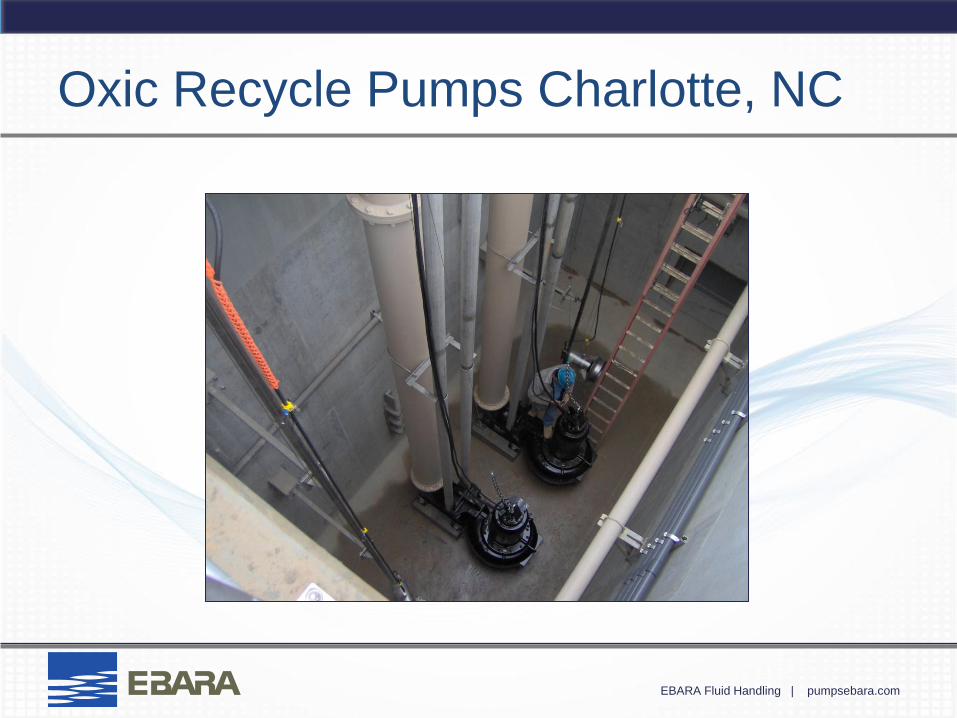
Oxic Recycle Pumps Charlotte, NC
EBARA Fluid Handling | pumpsebara.com
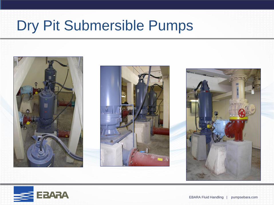
Dry Pit Submersible Pumps

EBARA Fluid Handling | pumpsebara.com

EBARA Fluid Handling | pumpsebara.com
Basic Hydraulics &
Pump Sizing
Ebara Fluid Handling Ebara International Corporation
1651 Cedar Line Drive
Rock Hill, SC 29730
(t) 803-327-5005 (f) 803-327-5097
www.pumpsebara.com
EBARA Fluid Handling | pumpsebara.com
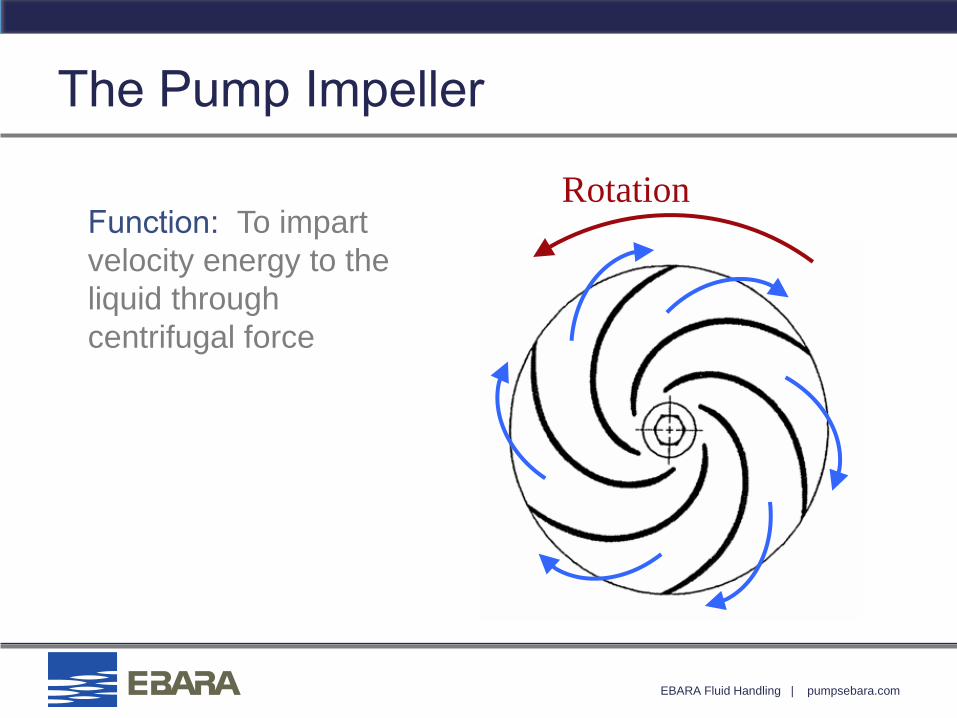
The Pump Impeller
Function: To impart
velocity energy to the
liquid through
centrifugal force
Rotation
EBARA Fluid Handling | pumpsebara.com
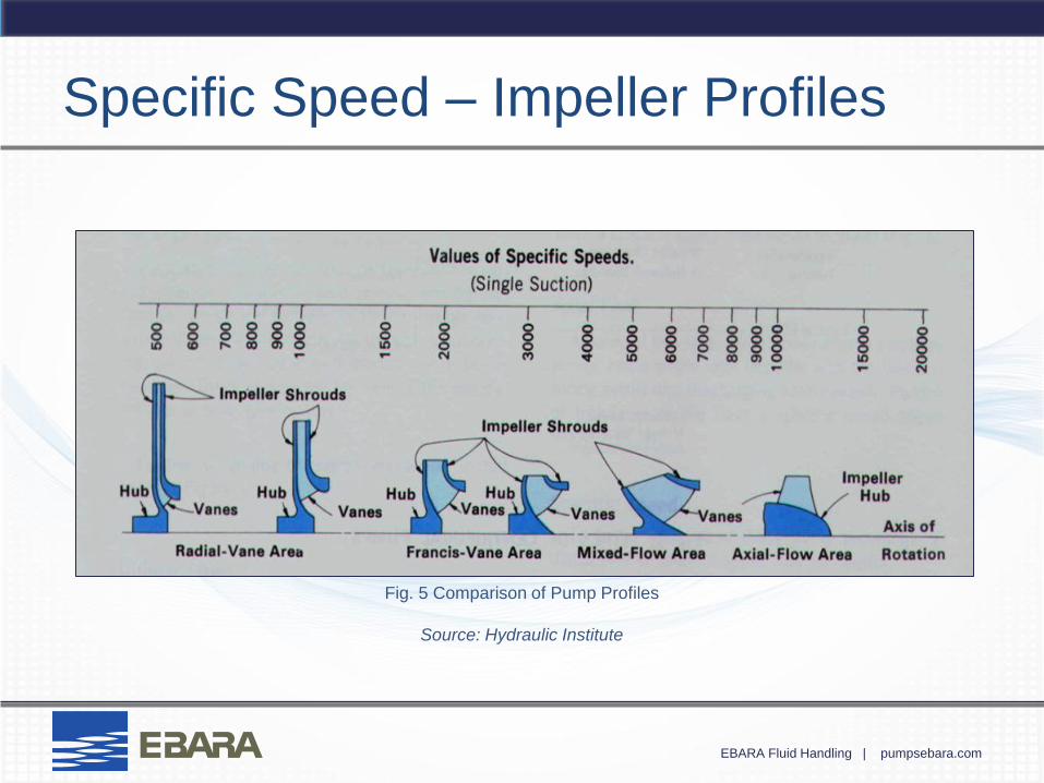
Specific Speed – Impeller Profiles
Fig. 5 Comparison of Pump Profiles
Source: Hydraulic Institute
EBARA Fluid Handling | pumpsebara.com
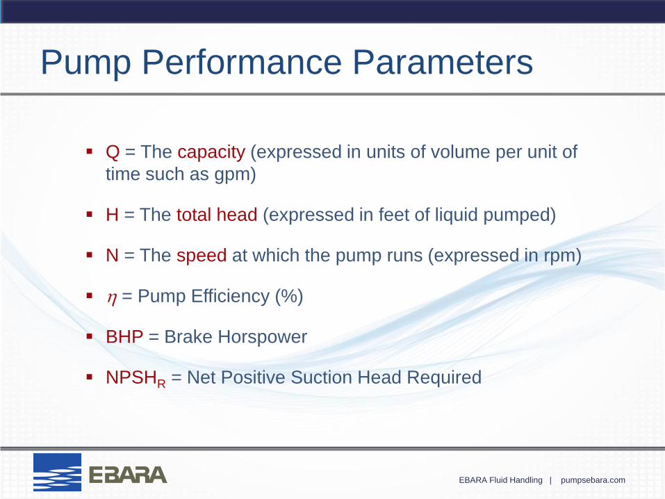
Pump Performance Parameters
Q = The capacity (expressed in units of volume per unit of
time such as gpm)
H = The total head (expressed in feet of liquid pumped)
N = The speed at which the pump runs (expressed in rpm)
h = Pump Efficiency (%)
BHP = Brake Horspower
NPSHR = Net Positive Suction Head Required
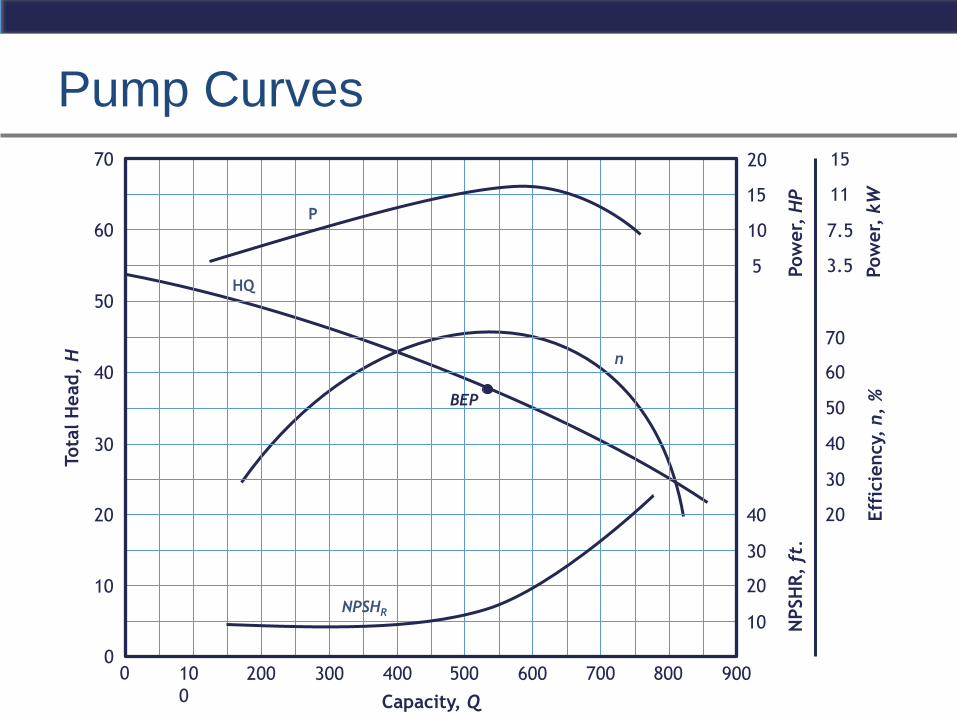
Pump Curves Tota
l H
ead,
H
Capacity, Q
HQ
0
10
20
30
50
40
60
70
n
P
NPSHR
BEP
200 300 10
0
500 600 400 800 700 0 900
Eff
icie
ncy,
n,
%
Pow
er,
HP
NPSH
R,
ft.
Pow
er,
kW
10
20
20
30
40
50
60
15
3.5
7.5
5
30
40
70
10
20
11
15
EBARA Fluid Handling | pumpsebara.com
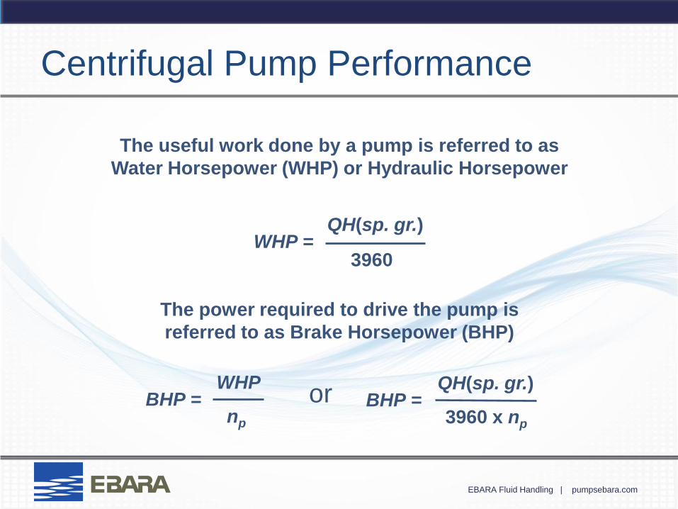
Centrifugal Pump Performance
The useful work done by a pump is referred to as
Water Horsepower (WHP) or Hydraulic Horsepower
WHP = QH(sp. gr.)
3960
The power required to drive the pump is
referred to as Brake Horsepower (BHP)
or BHP = WHP
np
BHP = QH(sp. gr.)
3960 x np
EBARA Fluid Handling | pumpsebara.com
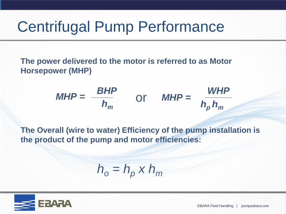
ho = hp x hm
The Overall (wire to water) Efficiency of the pump installation is
the product of the pump and motor efficiencies:
Centrifugal Pump Performance
The power delivered to the motor is referred to as Motor
Horsepower (MHP)
MHP = BHP
hm
_____ or MHP = WHP
hp hm
______
EBARA Fluid Handling | pumpsebara.com
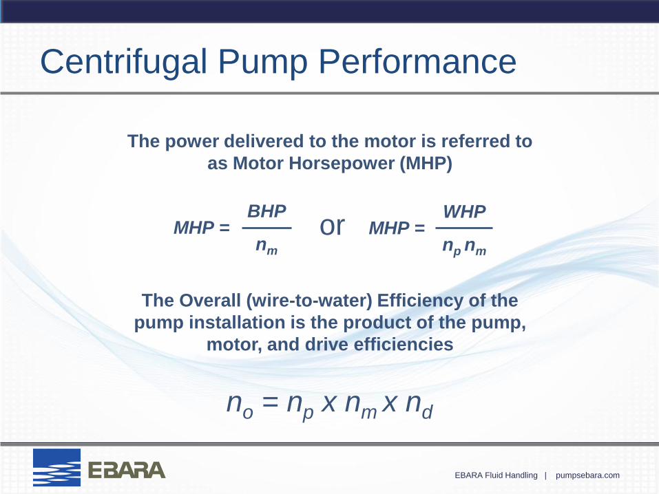
Centrifugal Pump Performance
The power delivered to the motor is referred to
as Motor Horsepower (MHP)
or MHP = BHP
nm
MHP = WHP
np nm
The Overall (wire-to-water) Efficiency of the
pump installation is the product of the pump,
motor, and drive efficiencies
no = np x nm x nd
EBARA Fluid Handling | pumpsebara.com
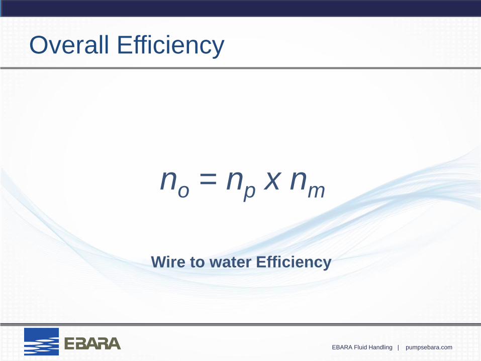
Overall Efficiency
no = np x nm
Wire to water Efficiency
EBARA Fluid Handling | pumpsebara.com
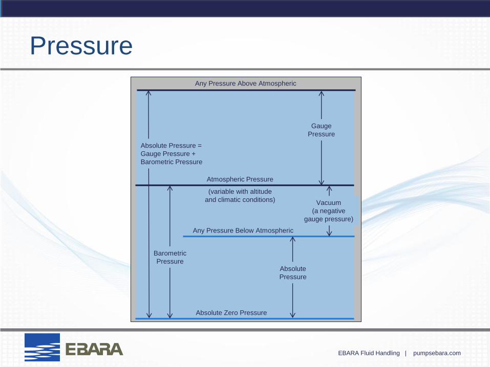
Pressure
Any Pressure Above Atmospheric
Gauge
Pressure
Atmospheric Pressure
(variable with altitude
and climatic conditions) Vacuum
(a negative
gauge pressure)
Any Pressure Below Atmospheric
Barometric
Pressure Absolute
Pressure
Absolute Zero Pressure
Absolute Pressure =
Gauge Pressure +
Barometric Pressure
EBARA Fluid Handling | pumpsebara.com
Pressure
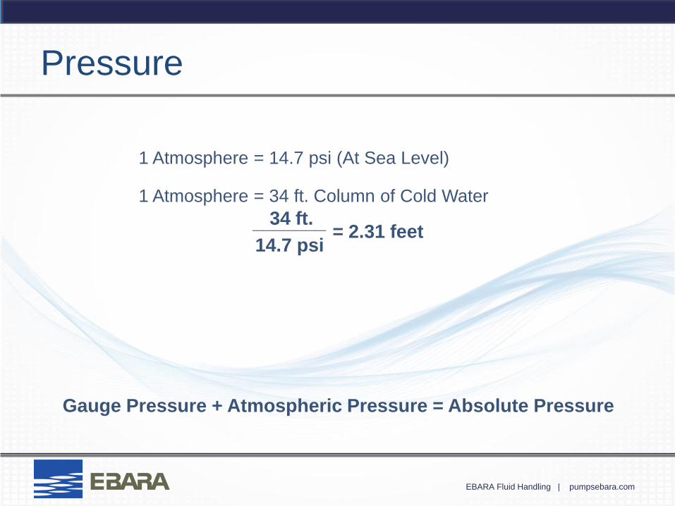
1 Atmosphere = 14.7 psi (At Sea Level)
1 Atmosphere = 34 ft. Column of Cold Water
= 2.31 feet 34 ft.
14.7 psi
_______
Gauge Pressure + Atmospheric Pressure = Absolute Pressure
EBARA Fluid Handling | pumpsebara.com
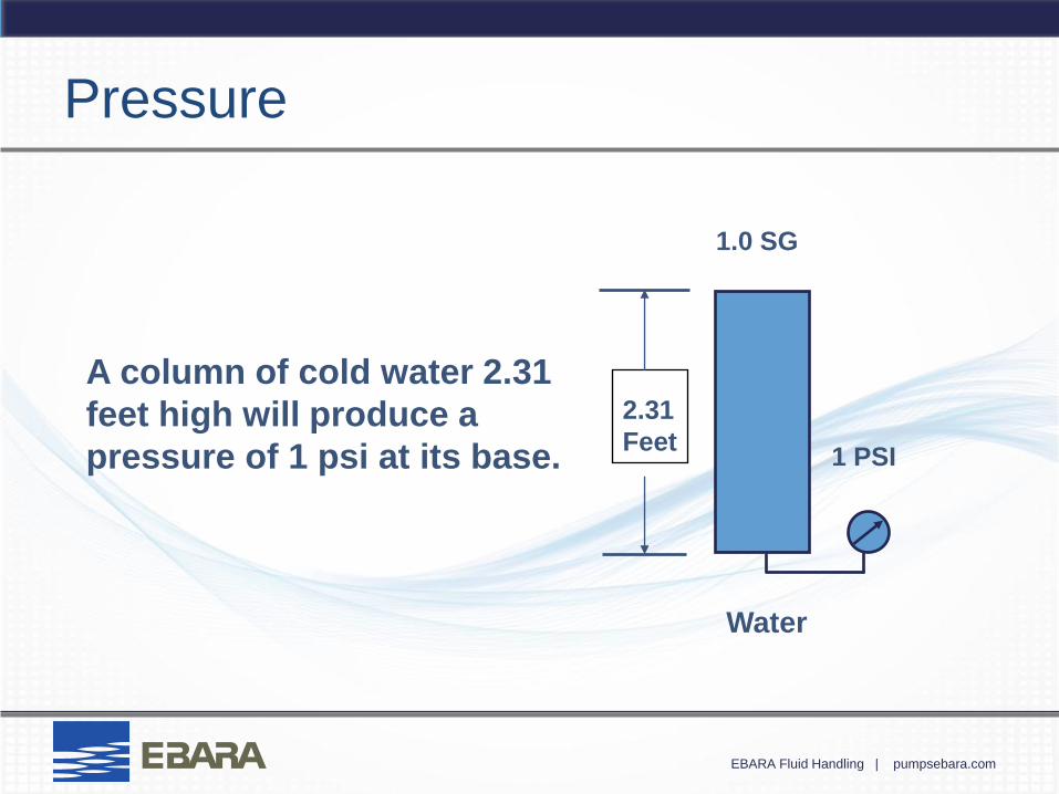
1.0 SG
2.31
Feet
Water
1 PSI
A column of cold water 2.31
feet high will produce a
pressure of 1 psi at its base.
Pressure
EBARA Fluid Handling | pumpsebara.com
Pressure
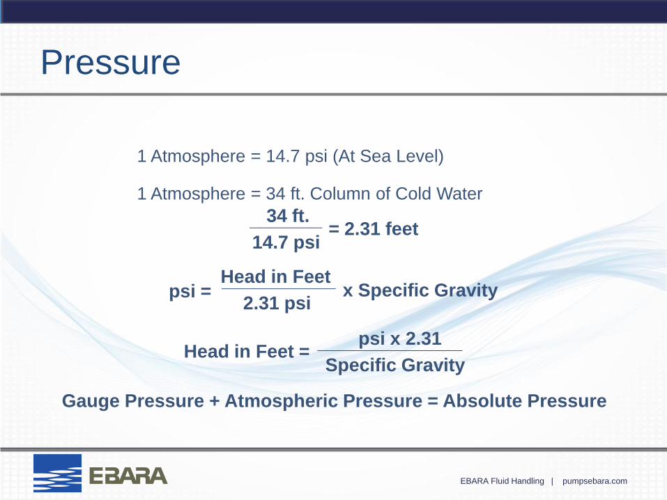
1 Atmosphere = 14.7 psi (At Sea Level)
1 Atmosphere = 34 ft. Column of Cold Water
Gauge Pressure + Atmospheric Pressure = Absolute Pressure
psi = Head in Feet
2.31 psi
___________ x Specific Gravity
psi x 2.31
Specific Gravity
______________ Head in Feet =
= 2.31 feet 34 ft.
14.7 psi
_______
EBARA Fluid Handling | pumpsebara.com
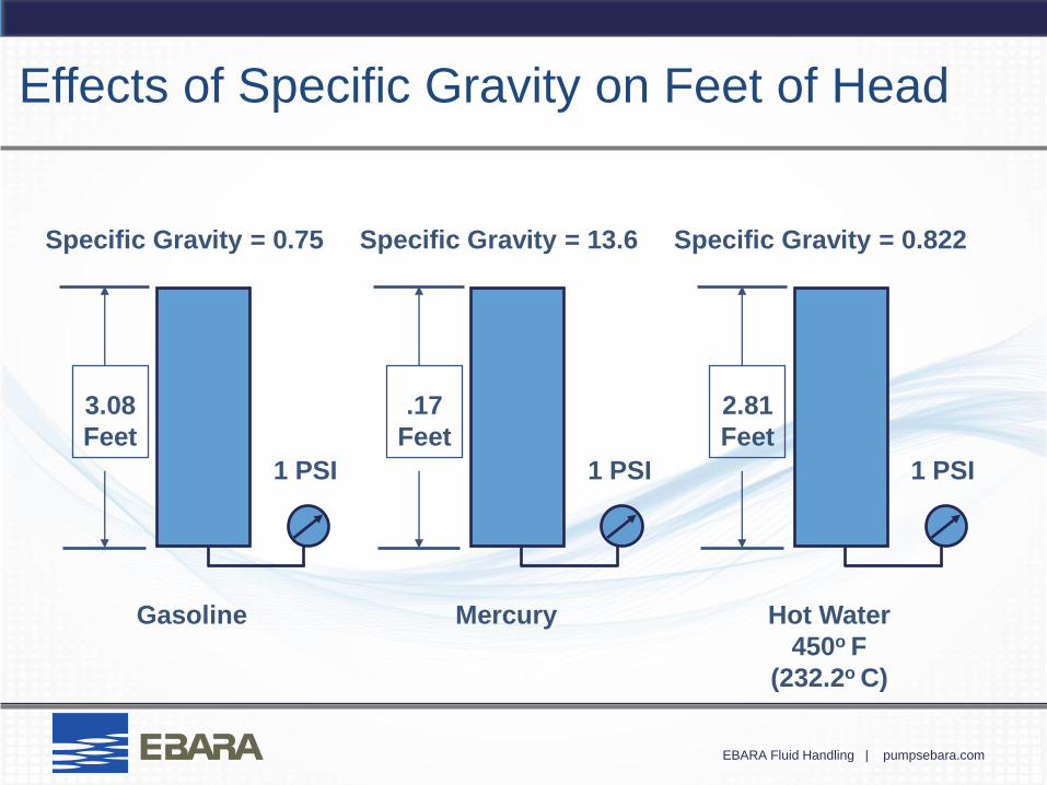
Specific Gravity = 0.75
3.08
Feet
Gasoline
1 PSI
.17
Feet
Mercury
1 PSI
Specific Gravity = 13.6
2.81
Feet
Hot Water
450o F
(232.2o C)
1 PSI
Specific Gravity = 0.822
Effects of Specific Gravity on Feet of Head

EBARA Fluid Handling | pumpsebara.com
Now let’s take a look at the
system…
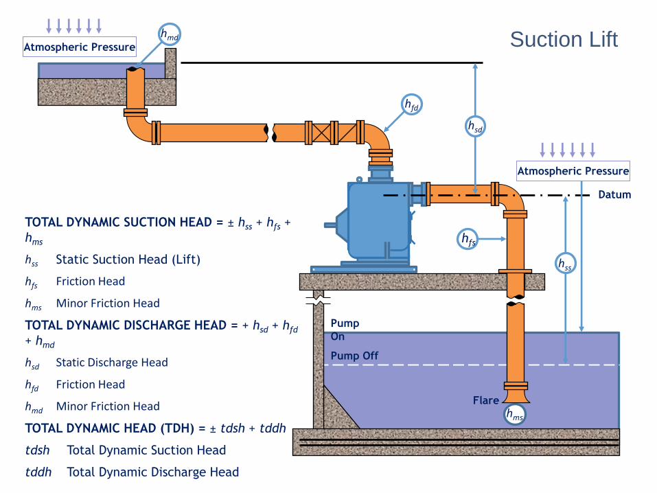
Atmospheric Pressure
TOTAL DYNAMIC SUCTION HEAD = ± hss + hfs +
hms
hss Static Suction Head (Lift)
hfs Friction Head
hms Minor Friction Head
TOTAL DYNAMIC DISCHARGE HEAD = + hsd + hfd
+ hmd
hsd Static Discharge Head
hfd Friction Head
hmd Minor Friction Head
TOTAL DYNAMIC HEAD (TDH) = ± tdsh + tddh
tdsh Total Dynamic Suction Head
tddh Total Dynamic Discharge Head
hsd
hfd
Atmospheric Pressure
hfs
hms
hmd
Flare
hss
Pump Off
Pump
On
Datum
Suction Lift
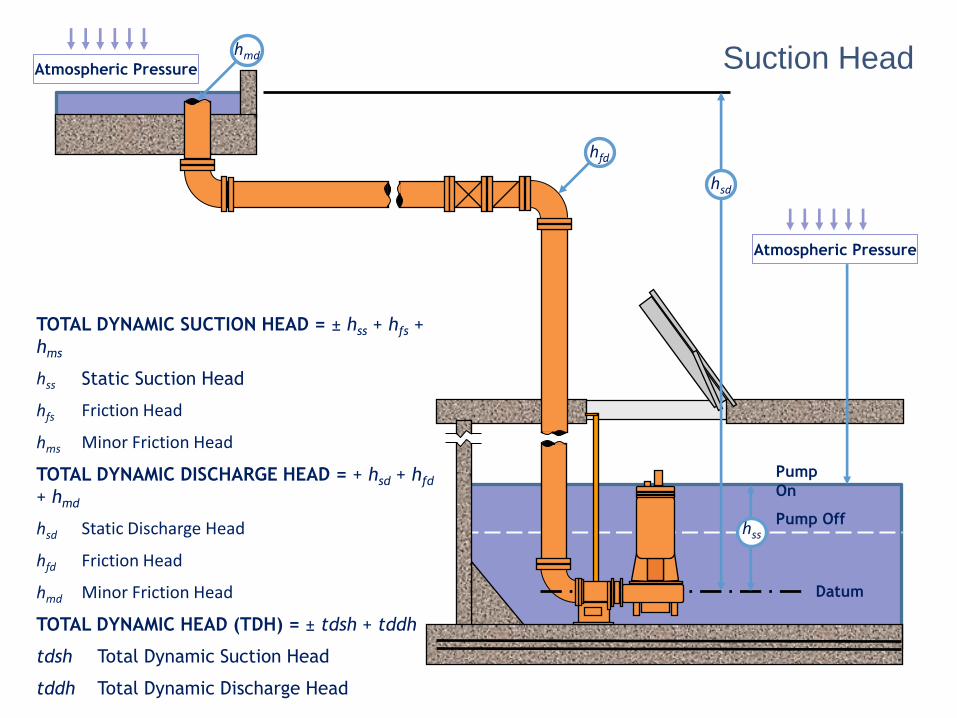
TOTAL DYNAMIC SUCTION HEAD = ± hss + hfs +
hms
hss Static Suction Head
hfs Friction Head
hms Minor Friction Head
TOTAL DYNAMIC DISCHARGE HEAD = + hsd + hfd
+ hmd
hsd Static Discharge Head
hfd Friction Head
hmd Minor Friction Head
TOTAL DYNAMIC HEAD (TDH) = ± tdsh + tddh
tdsh Total Dynamic Suction Head
tddh Total Dynamic Discharge Head
Atmospheric Pressure
hfd
Atmospheric Pressure
hmd
Pump Off
Pump
On
Datum
hsd
hss
Suction Head
EBARA Fluid Handling | pumpsebara.com
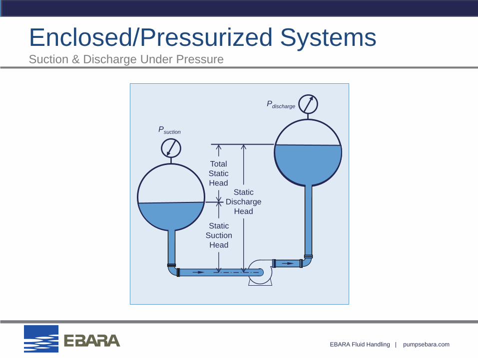
Enclosed/Pressurized Systems Suction & Discharge Under Pressure
Static
Discharge
Head
Total
Static
Head
Static
Suction
Head
Pdischarge
Psuction
EBARA Fluid Handling | pumpsebara.com
System Head
Static head
Difference in pressure on liquid surfaces
Friction head
Entrance and exit losses

EBARA Fluid Handling | pumpsebara.com
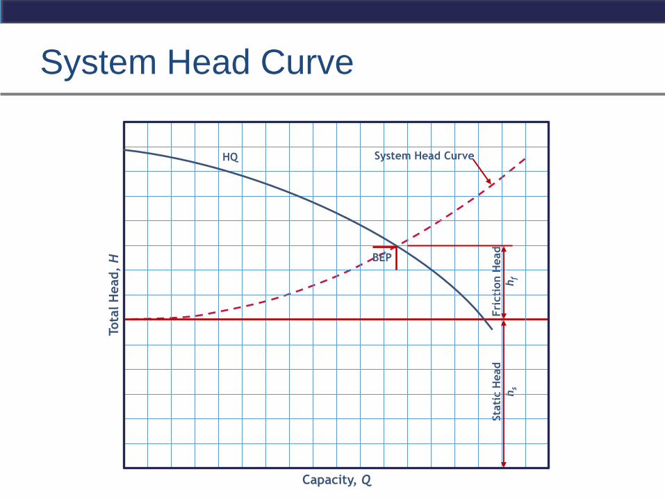
Total Head (Total Dynamic Head)
Static Discharge Head
+ Static Suction Lift or – Static Suction
Head
+ Friction Head (suction & discharge)
+ Differential Pressure (discharge vs.
suction)
Total Head (Total Dynamic Head)
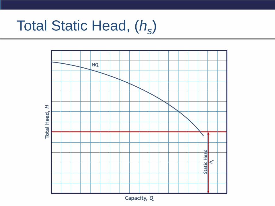
Total Static Head, (hs)
Tota
l H
ead,
H
Capacity, Q
Sta
tic H
ead
hs
HQ
EBARA Fluid Handling | pumpsebara.com
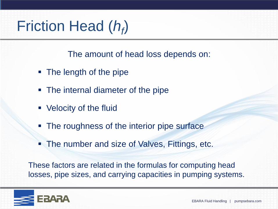
Friction Head (hf)
The amount of head loss depends on:
The length of the pipe
The internal diameter of the pipe
Velocity of the fluid
The roughness of the interior pipe surface
The number and size of Valves, Fittings, etc.
These factors are related in the formulas for computing head
losses, pipe sizes, and carrying capacities in pumping systems.
EBARA Fluid Handling | pumpsebara.com
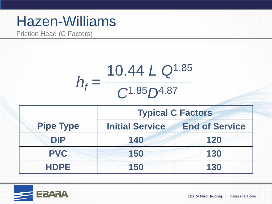
Hazen-Williams Friction Head (C Factors)
Pipe Type
Typical C Factors
Initial Service End of Service
DIP 140 120
PVC 150 130
HDPE 150 130
hf = 10.44 L Q1.85
C1.85D4.87
__________
EBARA Fluid Handling | pumpsebara.com
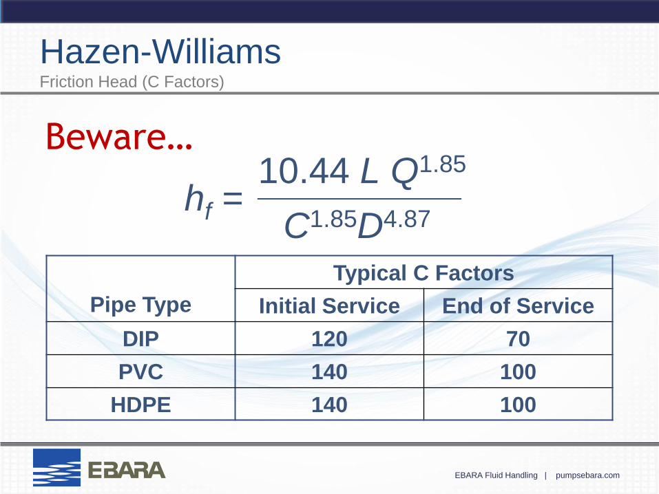
Pipe Type
Typical C Factors
Initial Service End of Service
DIP 120 70
PVC 140 100
HDPE 140 100
hf = 10.44 L Q1.85
C1.85D4.87
__________
Beware…
Hazen-Williams Friction Head (C Factors)
EBARA Fluid Handling | pumpsebara.com
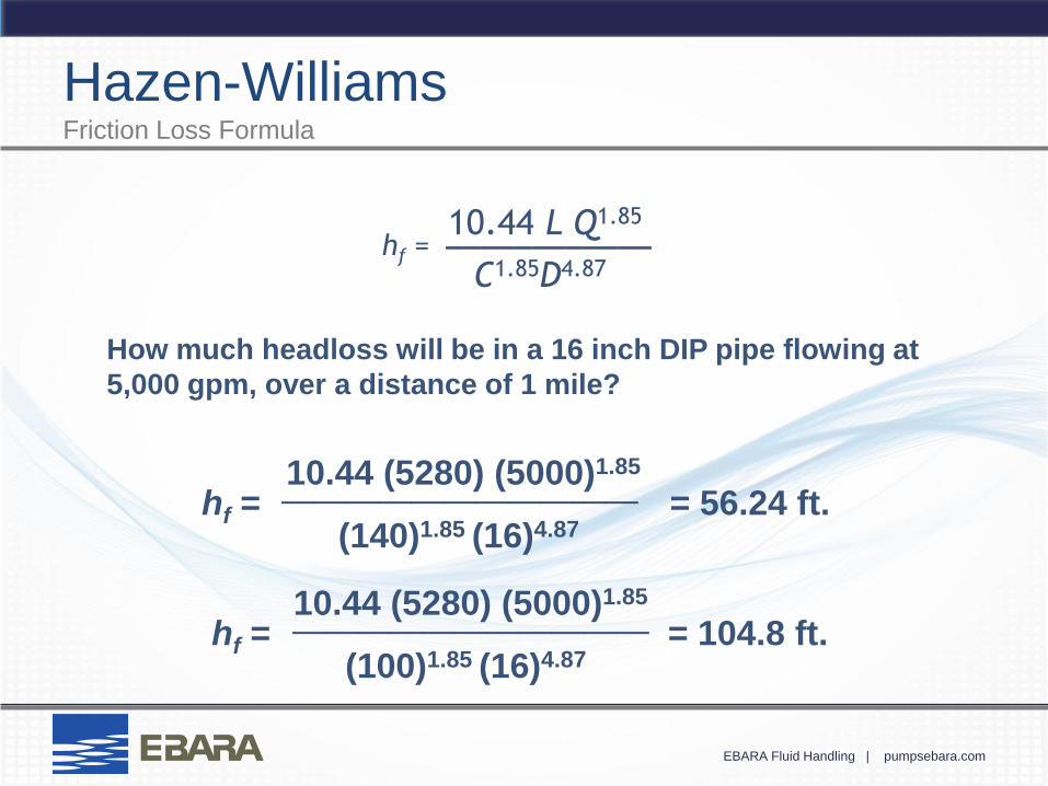
Hazen-Williams Friction Loss Formula
hf = 10.44 L Q1.85
C1.85D4.87
____________
How much headloss will be in a 16 inch DIP pipe flowing at
5,000 gpm, over a distance of 1 mile?
= 56.24 ft. 10.44 (5280) (5000)1.85
(140)1.85 (16)4.87
___________ hf =
= 104.8 ft. 10.44 (5280) (5000)1.85
(100)1.85 (16)4.87
___________ hf =
EBARA Fluid Handling | pumpsebara.com
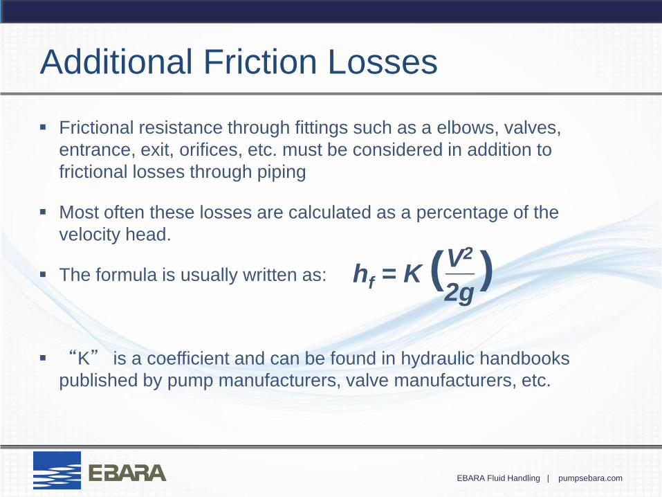
Additional Friction Losses
Frictional resistance through fittings such as a elbows, valves,
entrance, exit, orifices, etc. must be considered in addition to
frictional losses through piping
Most often these losses are calculated as a percentage of the
velocity head.
The formula is usually written as:
“K” is a coefficient and can be found in hydraulic handbooks
published by pump manufacturers, valve manufacturers, etc.
hf = K ( ) __ V2
2g
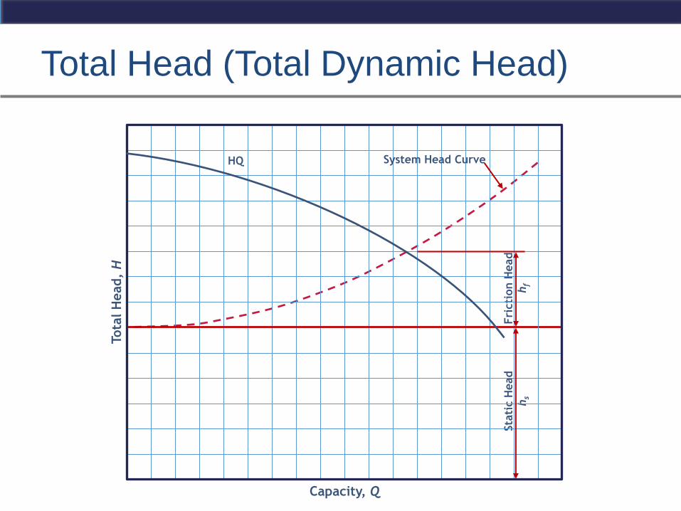
Total Head (Total Dynamic Head)
Tota
l H
ead,
H
Capacity, Q
Fri
cti
on H
ead
hf
Sta
tic H
ead
hs
System Head Curve HQ

Friction Head Effects of C Factor
HQ
C = 140
C = 100
Fri
cti
on
Head h
f
Sta
tic H
ead
hs
System Head
Curve
Capacity, Q
Tota
l H
ead,
H
The selection of C factor can have dramatic
effects on pump performance in the design
stage and over the life of the system.
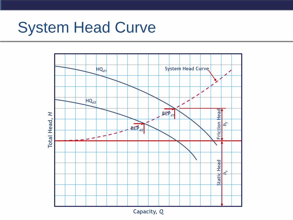
System Head Curve
Tota
l H
ead,
H
Capacity, Q
Fri
cti
on H
ead
hf
Sta
tic H
ead
hs
System Head Curve
BEPd1
HQd1
BEPd2
HQd2
System Head Curve
Tota
l H
ead,
H
Capacity, Q
Fri
cti
on H
ead
hf
Sta
tic H
ead
hs
System Head Curve
BEP
HQ
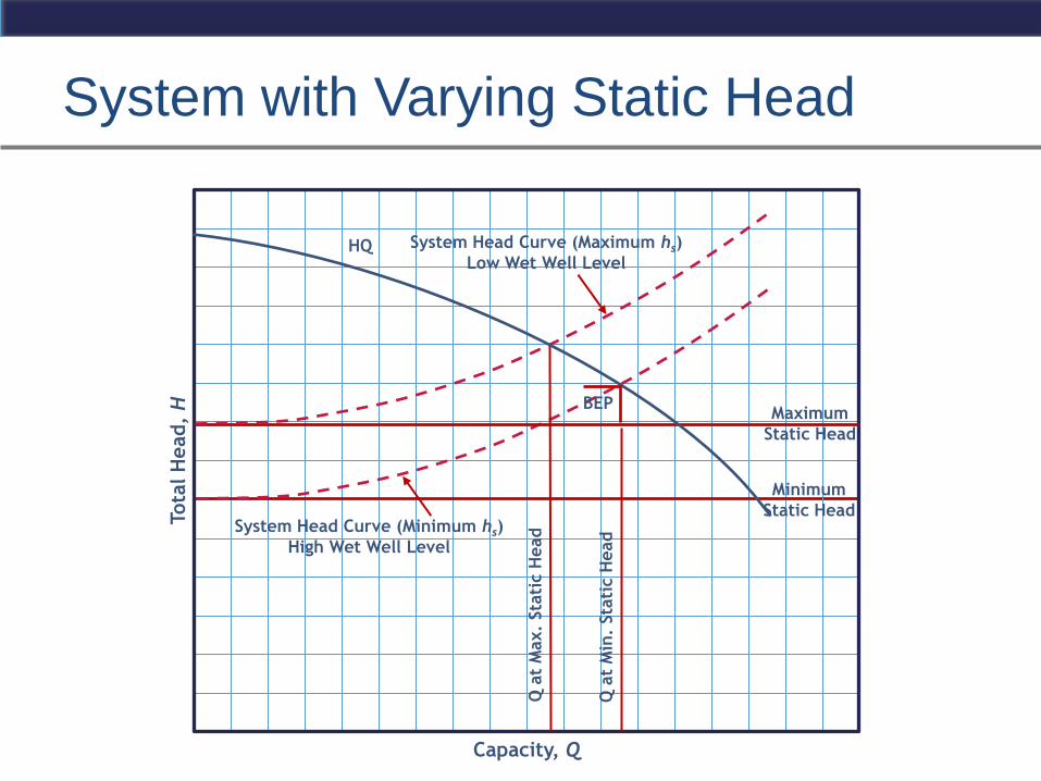
System with Varying Static Head
System Head Curve (Maximum hs)
Low Wet Well Level
Capacity, Q
Tota
l H
ead,
H
Minimum
Static Head
Maximum
Static Head
System Head Curve (Minimum hs)
High Wet Well Level
Q a
t M
in.
Sta
tic H
ead
Q a
t M
ax.
Sta
tic H
ead
HQ
BEP
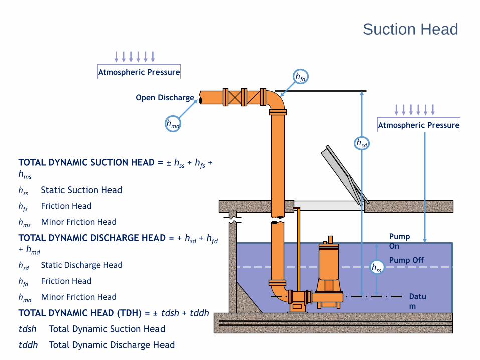
TOTAL DYNAMIC SUCTION HEAD = ± hss + hfs +
hms
hss Static Suction Head
hfs Friction Head
hms Minor Friction Head
TOTAL DYNAMIC DISCHARGE HEAD = + hsd + hfd
+ hmd
hsd Static Discharge Head
hfd Friction Head
hmd Minor Friction Head
TOTAL DYNAMIC HEAD (TDH) = ± tdsh + tddh
tdsh Total Dynamic Suction Head
tddh Total Dynamic Discharge Head
Atmospheric Pressure
hfd
Atmospheric Pressure
hmd
Pump Off
Pump
On
Datu
m
hss
Suction Head
hsd
Open Discharge
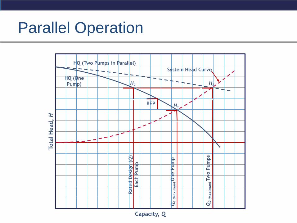
Parallel Operation
Capacity, Q
Tota
l H
ead,
H
Rate
d D
esi
gn (
Q)
Each P
um
p
Q1 (
Maxim
um
) O
ne P
um
p
HQ (Two Pumps in Parallel)
HQ (One
Pump)
Q2 (
Maxim
um
) Tw
o P
um
ps
System Head Curve
H1
H2 H2
BEP
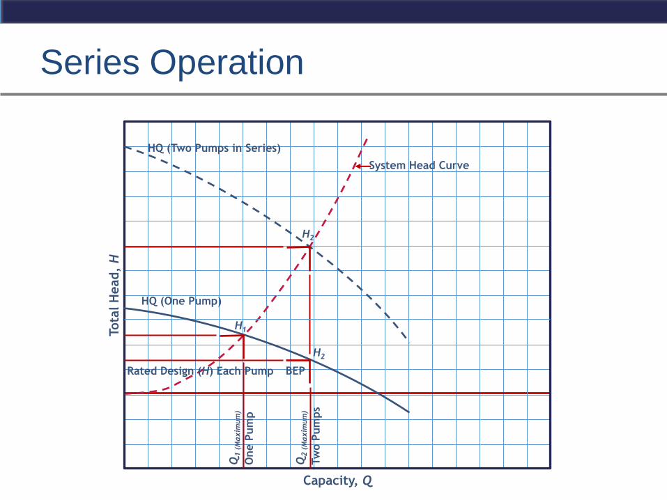
Series Operation
System Head Curve
Capacity, Q
Tota
l H
ead,
H
Q1 (
Maxim
um
) O
ne P
um
p
HQ (Two Pumps in Series)
HQ (One Pump)
Rated Design (H) Each Pump
H1
H2
Q2 (
Maxim
um
) Tw
o P
um
ps
H2
BEP
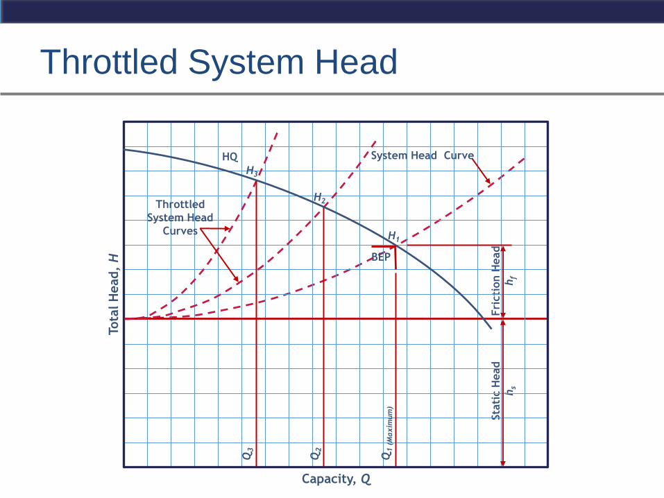
Throttled System Head
Tota
l H
ead,
H
Capacity, Q
Fri
cti
on H
ead
hf
Sta
tic H
ead
hs
System Head Curve HQ
H2
H1
BEP
H3
Q1 (
Maxim
um
)
Q2
Q3
Throttled
System Head
Curves
EBARA Fluid Handling | pumpsebara.com
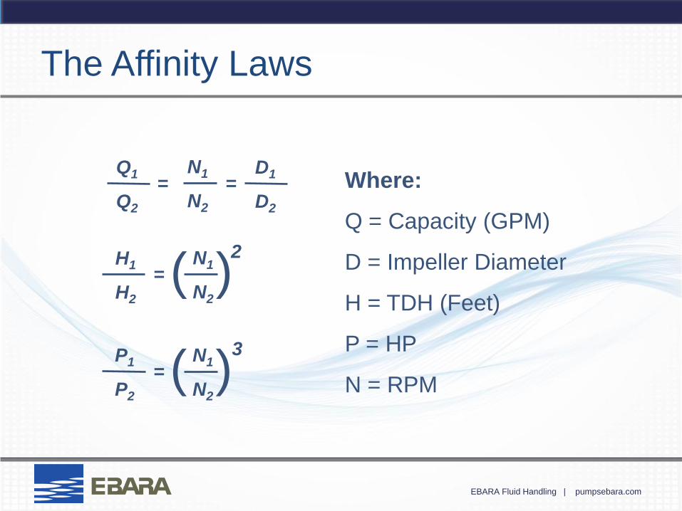
The Affinity Laws
Where:
Q = Capacity (GPM)
D = Impeller Diameter
H = TDH (Feet)
P = HP
N = RPM
= = D1
D2
N1
N2
Q1
Q2
= H1
H2
2
( ) N1
N2
= P1
P2
3
( ) N1
N2
EBARA Fluid Handling | pumpsebara.com
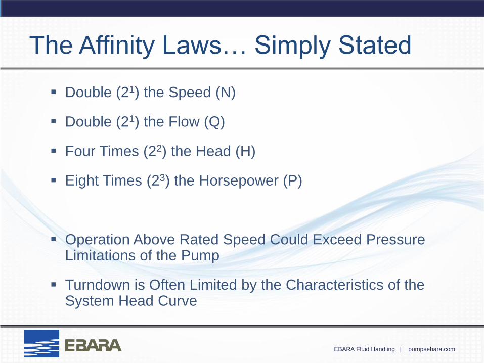
The Affinity Laws… Simply Stated
Double (21) the Speed (N)
Double (21) the Flow (Q)
Four Times (22) the Head (H)
Eight Times (23) the Horsepower (P)
Operation Above Rated Speed Could Exceed Pressure Limitations of the Pump
Turndown is Often Limited by the Characteristics of the System Head Curve
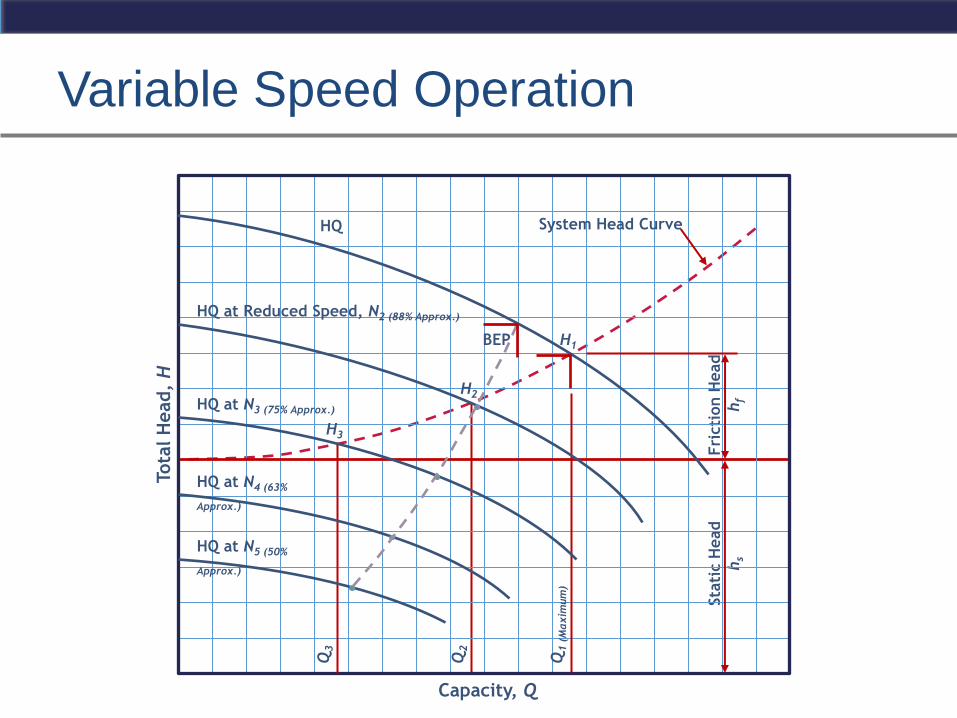
Variable Speed Operation
Tota
l H
ead,
H
Fri
cti
on H
ead
hf
Sta
tic H
ead
hs
System Head Curve HQ
H1
Capacity, Q
Q1 (
Maxim
um
)
Q2
H2
H3
Q3
HQ at Reduced Speed, N2 (88% Approx.)
HQ at N3 (75% Approx.)
HQ at N4 (63%
Approx.)
HQ at N5 (50%
Approx.)
BEP
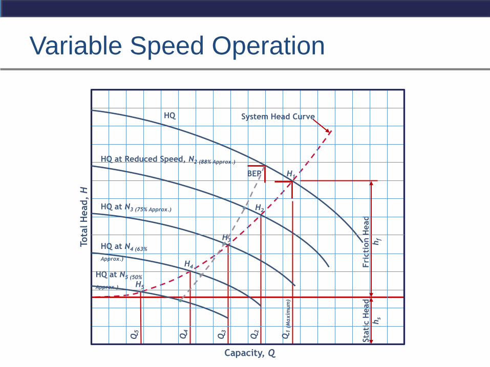
Variable Speed Operation
Tota
l H
ead,
H
Fri
cti
on H
ead
hf
Sta
tic H
ead
hs
System Head Curve HQ
BEP H1
Capacity, Q
Q1 (
Maxim
um
)
Q3
H2
H3
Q5
HQ at Reduced Speed, N2 (88% Approx.)
HQ at N3 (75% Approx.)
HQ at N4 (63%
Approx.)
HQ at N5 (50%
Approx.)
H4
H5
Q4
Q2
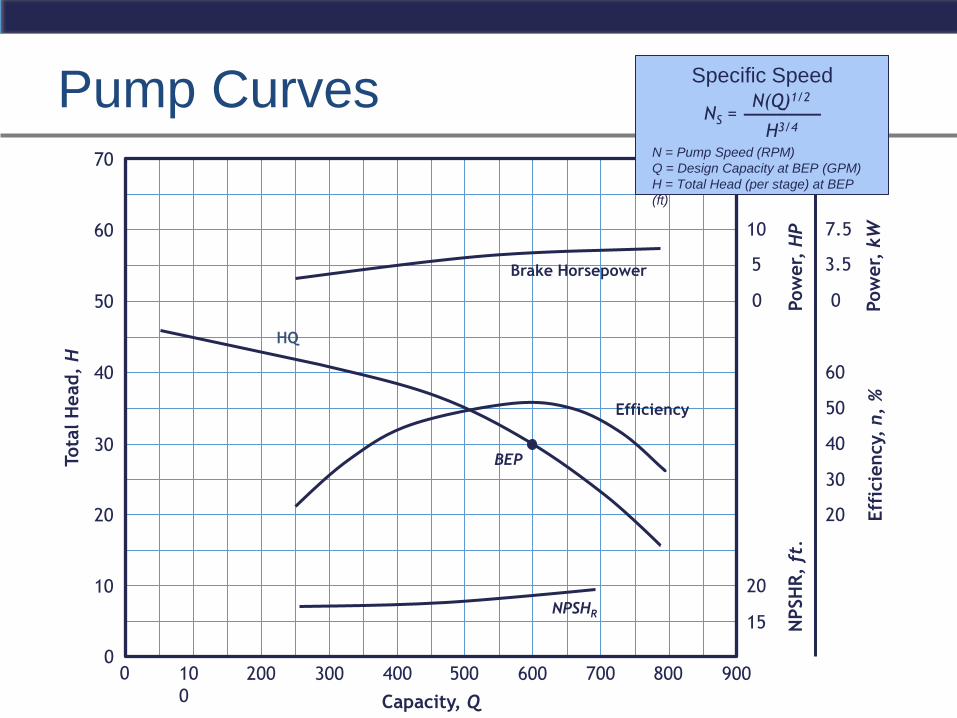
Pump Curves Tota
l H
ead,
H
Capacity, Q
200 300 10
0
500 600 400 800 900 700 0 0
10
20
30
50
40
60
70
Eff
icie
ncy,
n,
%
Pow
er,
HP
NPSHR
NPSH
R,
ft.
Pow
er,
kW
15
20
20
30
40
50
60
5
10
3.5
7.5
0 0
BEP
Brake Horsepower
HQ
Efficiency
NS = N(Q)1/2
H3/4
_______
N = Pump Speed (RPM)
Q = Design Capacity at BEP (GPM)
H = Total Head (per stage) at BEP
(ft)
Specific Speed
EBARA Fluid Handling | pumpsebara.com
Pump Operation & BEP Best Efficiency Point
Right of BEP (Cavitation)
Left of BEP (Internal Recirculation)
Shaft Deflection
Thrust Loads
Radial
Axial (Pump-out Vanes)
EBARA Fluid Handling | pumpsebara.com
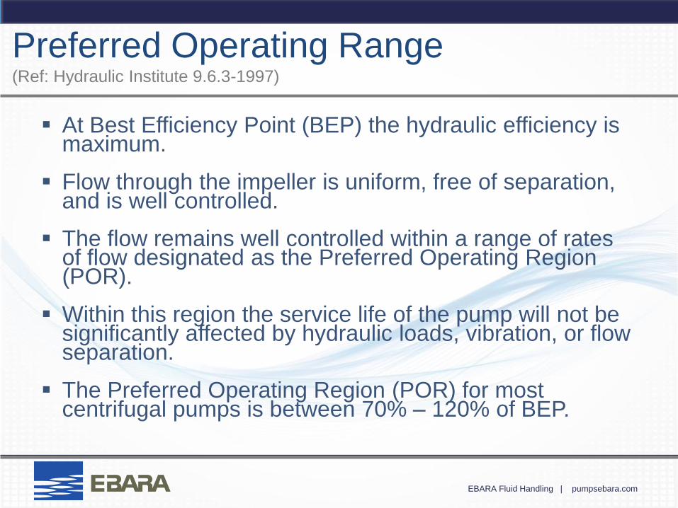
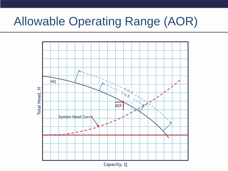
Preferred Operating Range (Ref: Hydraulic Institute 9.6.3-1997)
At Best Efficiency Point (BEP) the hydraulic efficiency is maximum.
Flow through the impeller is uniform, free of separation, and is well controlled.
The flow remains well controlled within a range of rates of flow designated as the Preferred Operating Region (POR).
Within this region the service life of the pump will not be significantly affected by hydraulic loads, vibration, or flow separation.
The Preferred Operating Region (POR) for most centrifugal pumps is between 70% – 120% of BEP.
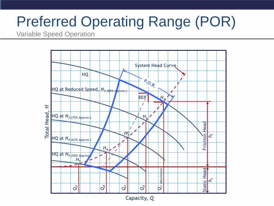
Preferred Operating Range (POR) Variable Speed Operation
Tota
l H
ead,
H
Fri
cti
on H
ead
hf
Sta
tic H
ead
hs
System Head Curve
HQ
BEP H1
Capacity, Q
Q1 (
Maxim
um
)
Q3
H2
H3
Q5
HQ at N3 (75% Approx.)
HQ at N4 (63% Approx.)
H4
H5
Q4
Q2
HQ at N5 (50% Approx.)
HQ at Reduced Speed, N2 (88% Approx.)
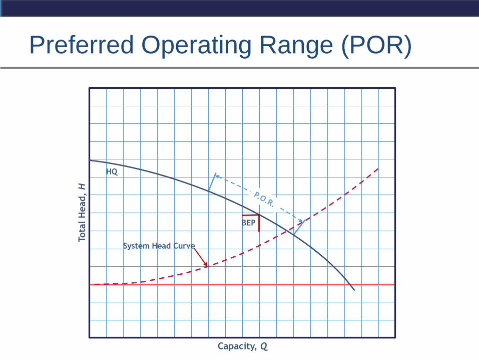
Preferred Operating Range (POR)
Tota
l H
ead,
H
Capacity, Q
System Head Curve
HQ
BEP
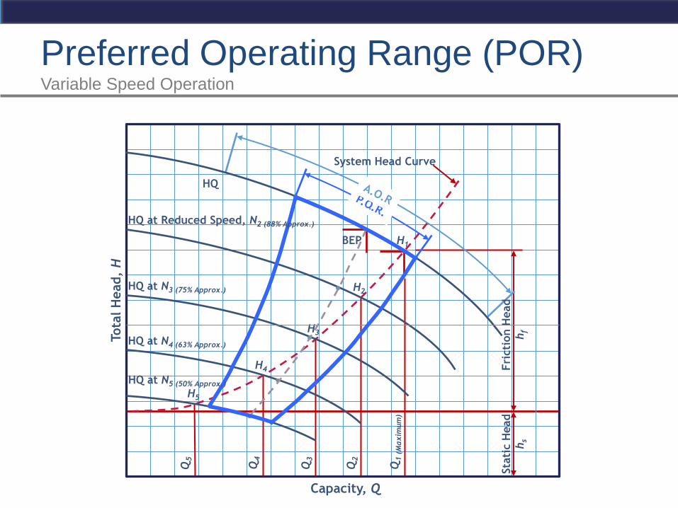
Preferred Operating Range (POR) Variable Speed Operation
Tota
l H
ead,
H
Fri
cti
on H
ead
hf
Sta
tic H
ead
hs
System Head Curve
HQ
BEP H1
Capacity, Q
Q1 (
Maxim
um
)
Q3
H2
H3
Q5
HQ at N3 (75% Approx.)
HQ at N4 (63% Approx.)
H4
H5
Q4
Q2
HQ at N5 (50% Approx.)
HQ at Reduced Speed, N2 (88% Approx.)
Allowable Operating Range (AOR)
Tota
l H
ead,
H
Capacity, Q
System Head Curve
HQ
BEP
EBARA Fluid Handling | pumpsebara.com
Cavitation
Occurs when the absolute pressure within
an impeller falls below the vapor pressure of
the liquid, and bubbles of vapor are formed.
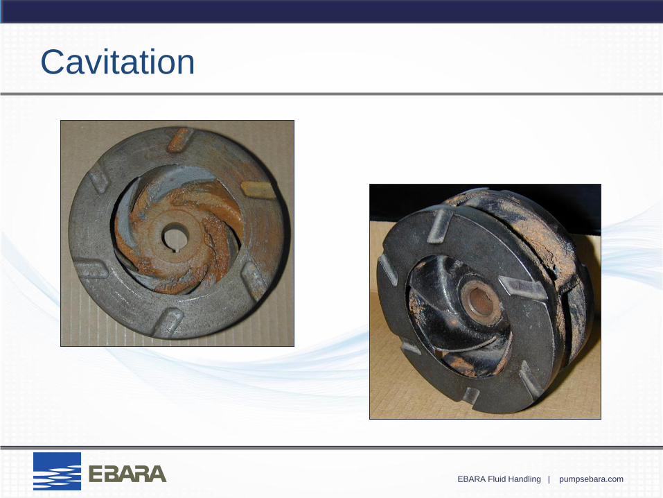
Signs include: noise, vibration, decreased
performance (head-capacity), increased
horsepower resulting from reduced efficiency,
and - over time - damage to the impeller by
pitting and erosion.
EBARA Fluid Handling | pumpsebara.com
Cavitation
EBARA Fluid Handling | pumpsebara.com
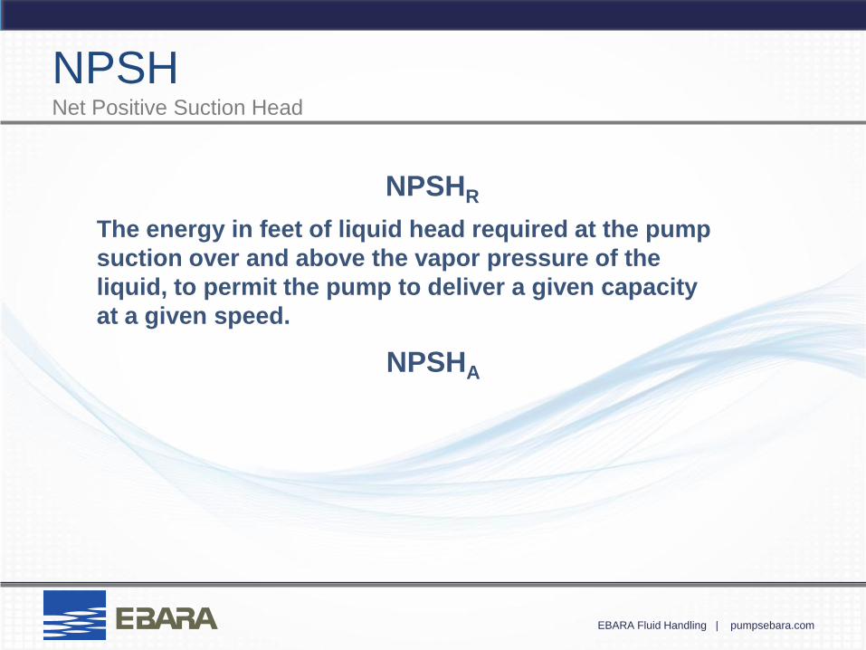
The energy in feet of liquid head required at the pump
suction over and above the vapor pressure of the
liquid, to permit the pump to deliver a given capacity
at a given speed.
NPSH Net Positive Suction Head
NPSHR
NPSHA
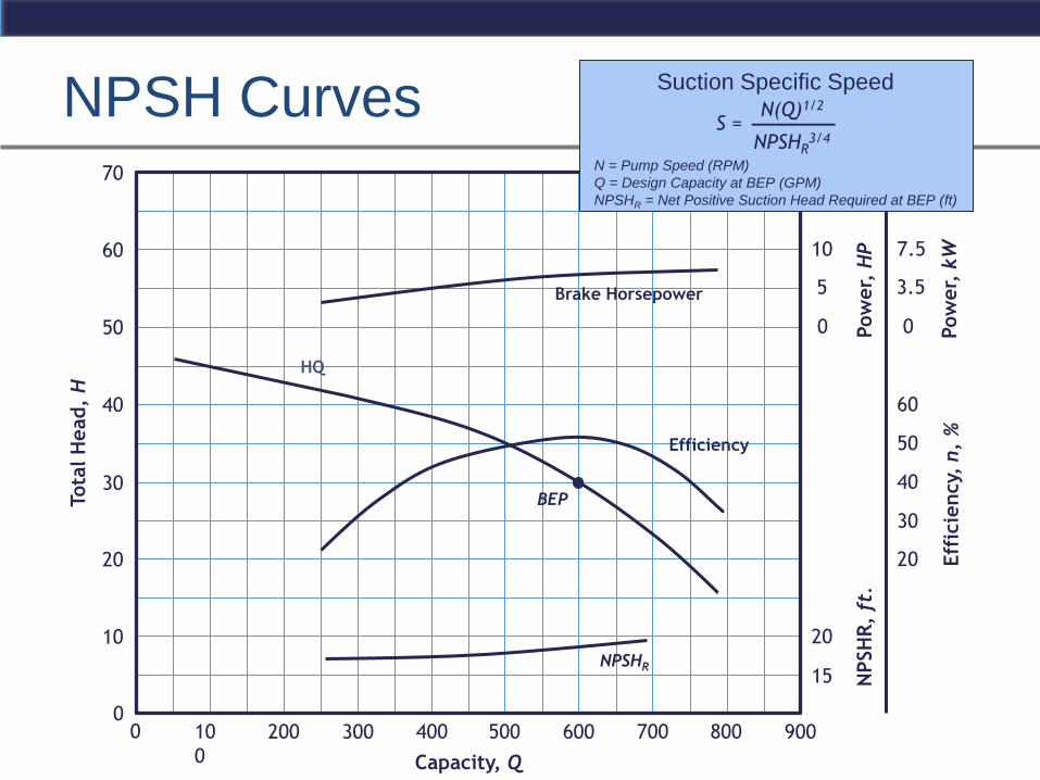
NPSH Curves Tota
l H
ead,
H
Capacity, Q
200 300 10
0
500 600 400 800 900 700 0 0
10
20
30
50
40
60
70
Eff
icie
ncy,
n,
%
Pow
er,
HP
NPSHR
NPSH
R,
ft.
Pow
er,
kW
15
20
20
30
40
50
60
5
10
3.5
7.5
0 0
BEP
Brake Horsepower
HQ
Efficiency
N = Pump Speed (RPM)
Q = Design Capacity at BEP (GPM)
NPSHR = Net Positive Suction Head Required at BEP (ft)
Suction Specific Speed
S = N(Q)1/2
NPSHR3/4
_______
EBARA Fluid Handling | pumpsebara.com
Net Positive Suction Head
NPSHR < NPSHA