
Basic Electronics - VTU · PDF filePHYS 401 Physics of Ham Radio 25 Basic Electronics Chapter...
31
PHYS 401 Physics of Ham Radio 25 Basic Electronics Chapter 2 Basic Electrical Principles and the Functions of Components Figures in this course book are reproduced with the permission of the American Radio Relay League. This booklet was compiled by John P. Cross AB5OX
-
Upload
truongphuc -
Category
Documents
-
view
220 -
download
1
Transcript of Basic Electronics - VTU · PDF filePHYS 401 Physics of Ham Radio 25 Basic Electronics Chapter...

PHYS 401 Physics of Ham Radio25
Basic Electronics
Chapter 2Basic Electrical Principles andthe Functions of Components
Figures in this course book arereproduced with the permission ofthe American Radio Relay League.
This booklet was compiled byJohn P. Cross AB5OX
PHYS 401 Physics of Ham Radio26
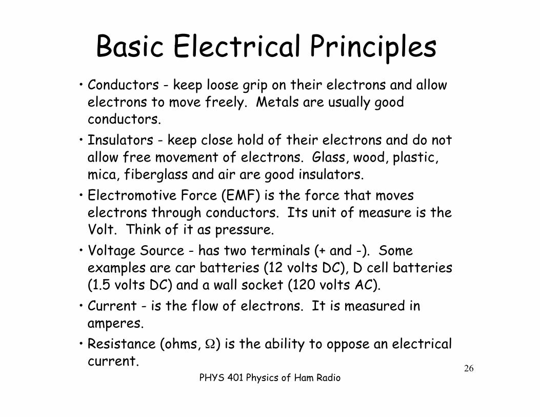
Basic Electrical Principles• Conductors - keep loose grip on their electrons and allow
electrons to move freely. Metals are usually goodconductors.
• Insulators - keep close hold of their electrons and do notallow free movement of electrons. Glass, wood, plastic,mica, fiberglass and air are good insulators.
• Electromotive Force (EMF) is the force that moveselectrons through conductors. Its unit of measure is theVolt. Think of it as pressure.
• Voltage Source - has two terminals (+ and -). Someexamples are car batteries (12 volts DC), D cell batteries(1.5 volts DC) and a wall socket (120 volts AC).
• Current - is the flow of electrons. It is measured inamperes.
• Resistance (ohms, Ω) is the ability to oppose an electricalcurrent.

PHYS 401 Physics of Ham Radio27

PHYS 401 Physics of Ham Radio28
Circuit DefinitionsA circuit must close to be complete!
PHYS 401 Physics of Ham Radio29
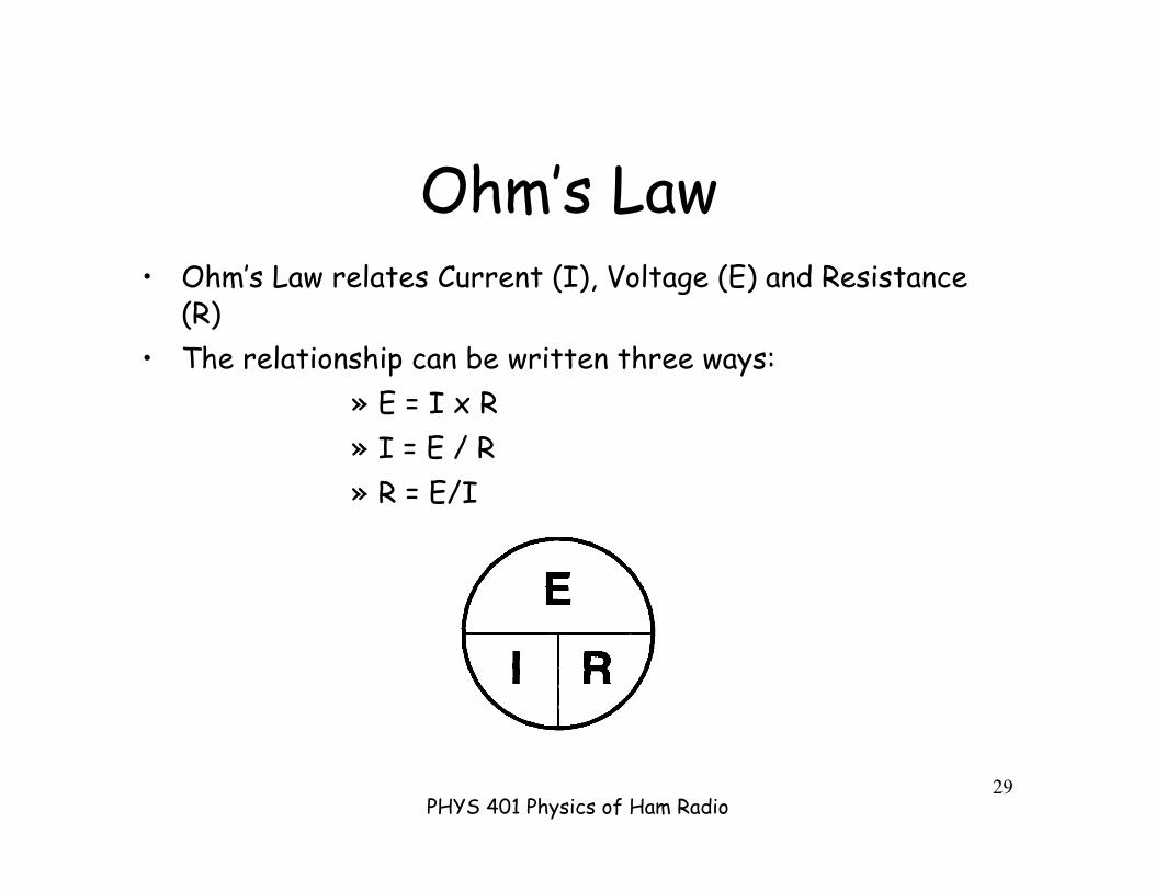
Ohm’s Law• Ohm’s Law relates Current (I), Voltage (E) and Resistance
(R)• The relationship can be written three ways:
» E = I x R» I = E / R» R = E/I

PHYS 401 Physics of Ham Radio30
PHYS 401 Physics of Ham Radio31
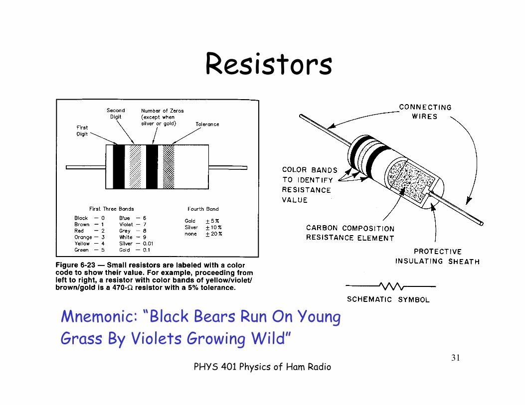
Resistors
Mnemonic: “Black Bears Run On YoungGrass By Violets Growing Wild”
PHYS 401 Physics of Ham Radio32
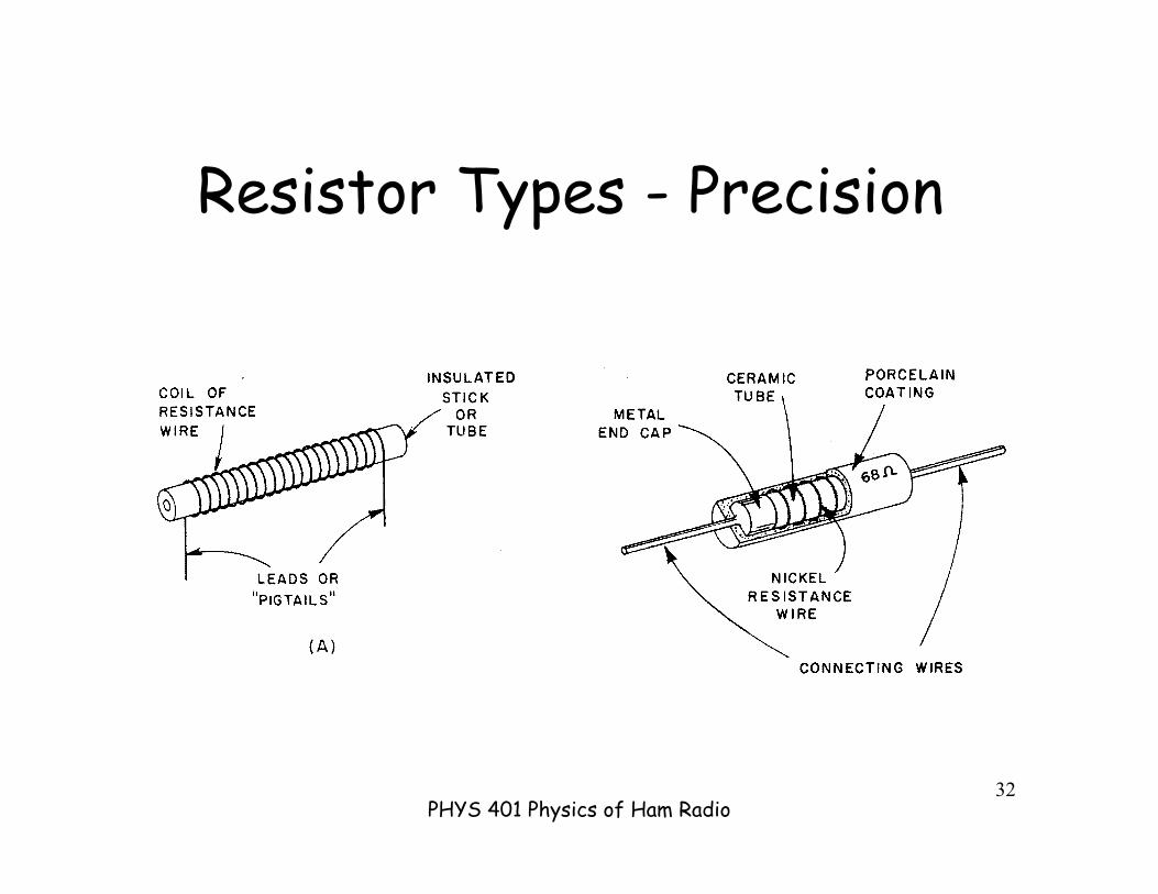
Resistor Types - Precision

PHYS 401 Physics of Ham Radio33
Resistors - Film Type

PHYS 401 Physics of Ham Radio34
Resistors - Variable
PHYS 401 Physics of Ham Radio35
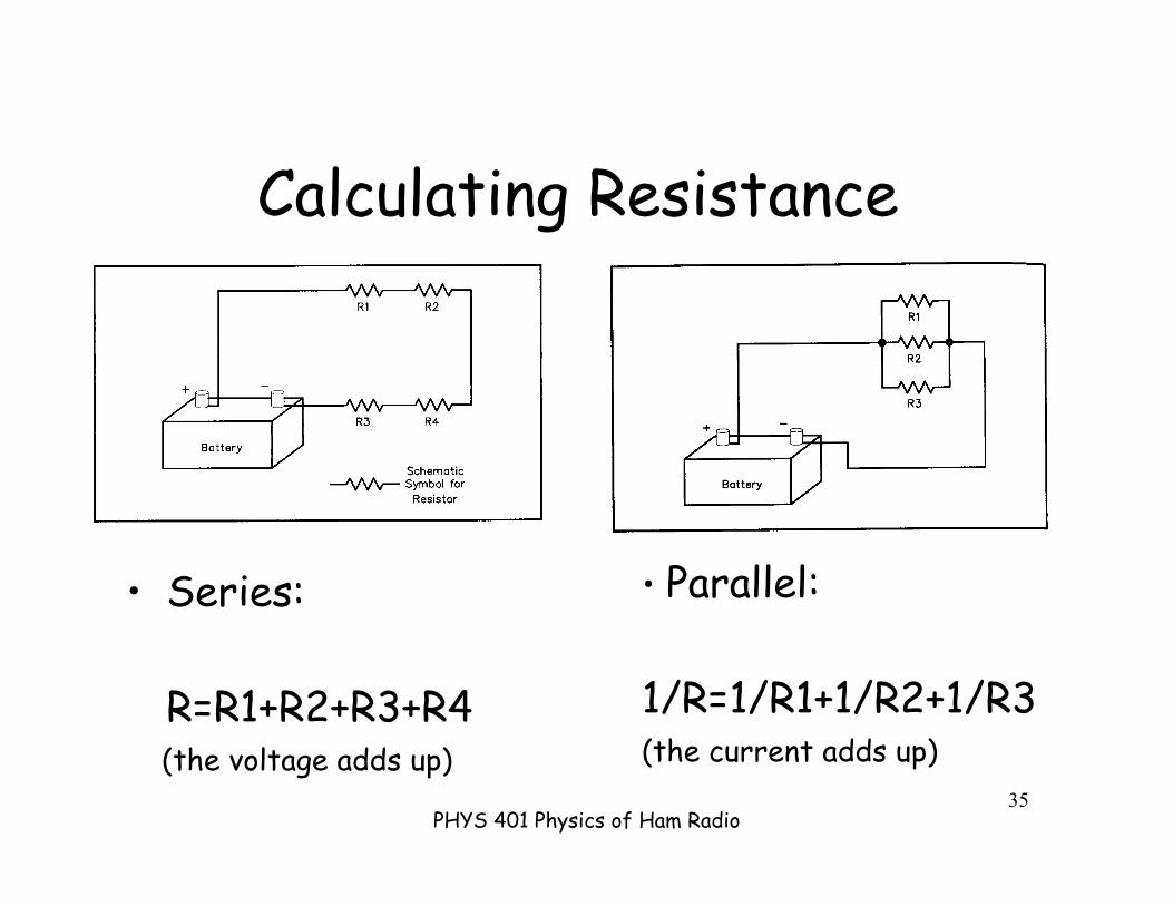
Calculating Resistance
• Series:
R=R1+R2+R3+R4 (the voltage adds up)
• Parallel:
1/R=1/R1+1/R2+1/R3(the current adds up)
PHYS 401 Physics of Ham Radio36
Capacitors
• Capacitors store energy in an electric field• Basic unit of capacitance is the farad (f)• Series: 1/C=1/C1+1/C2+1/C3• Parallel: C=C1+C2+C3• Capacitance is determined by 3 factors:
» plate surface area» plate spacing» insulating material (dielectric)

PHYS 401 Physics of Ham Radio37
Variables DeterminingCapacitance

PHYS 401 Physics of Ham Radio38
Parallel Capacitors Increase PlateArea; increase charge so C
PHYS 401 Physics of Ham Radio39
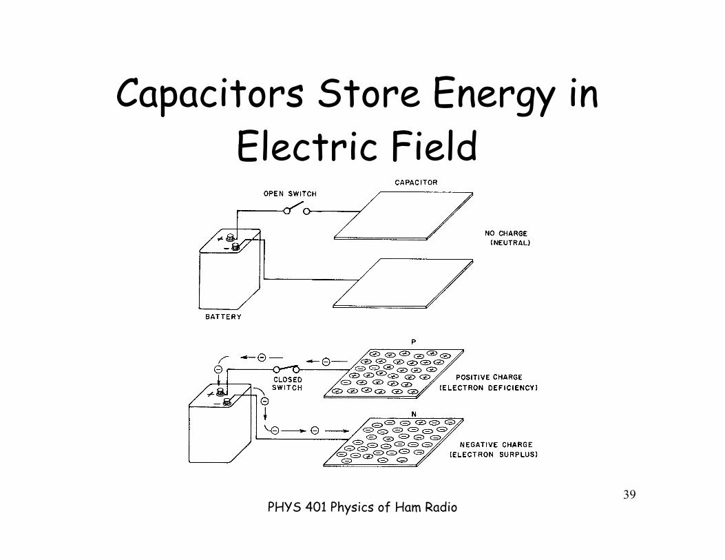
Capacitors Store Energy inElectric Field
PHYS 401 Physics of Ham Radio40
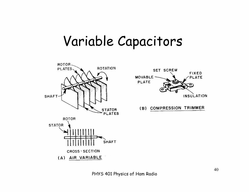
Variable Capacitors

PHYS 401 Physics of Ham Radio41
Inductors
• Inductors store energy in a magnetic field(like a little electromagnet)
• Basic unit of inductance is the henry (h)• Parallel: 1/L=1/L1+1/L2+1/L3• Series: L=L1+L2+L3• Inductance is determined by 4 factors:
» number of turns» permeability of the core» cross sectional area of the core» spacing of the turns

PHYS 401 Physics of Ham Radio42
Variables DeterminingInductance

PHYS 401 Physics of Ham Radio43
Inductors Store Energy inMagnetic Field
Current flow-->
Electron flow-->
Note: currentflows from + to -,but is carried byelectrons whichflow from - to +

PHYS 401 Physics of Ham Radio44
Types of Inductors
PHYS 401 Physics of Ham Radio45
Power
• Power is the rate of energy consumption.• The basic unit of power is the watt (W)• Power can be calculated as follows:
»P = I x E• Since E = I x R, you can also say:
»P = I2 x R• Since I = E / R, you can also say:
»P = E2 / R

PHYS 401 Physics of Ham Radio46
Meters - Measuring CurrentAmmetermust bepart of thecircuit tomeasurethe current
VOM -multimeterthatmeasuresE, I, R
PHYS 401 Physics of Ham Radio47
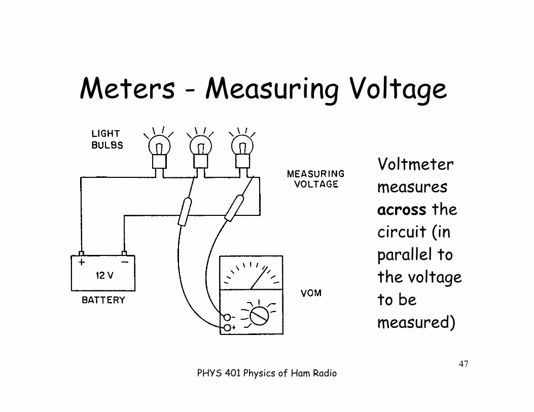
Meters - Measuring Voltage
Voltmetermeasuresacross thecircuit (inparallel tothe voltageto bemeasured)
PHYS 401 Physics of Ham Radio48
Meters - Measuring Resistance
Ohmmeter: measures across the resistor (butbe sure the circuit is not turned on “hot”).Puts in a known voltage and measures thecurrent, so it requires a battery. If thecircuit is energized, will give the wrong reading!
Never leave a multimeter set at “ohms” - willrun down its battery!

PHYS 401 Physics of Ham Radio49
Meters - Changing Range

PHYS 401 Physics of Ham Radio50
Schematic Symbol Examples
PHYS 401 Physics of Ham Radio51
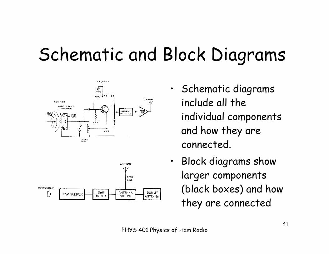
Schematic and Block Diagrams
• Schematic diagramsinclude all theindividual componentsand how they areconnected.
• Block diagrams showlarger components(black boxes) and howthey are connected
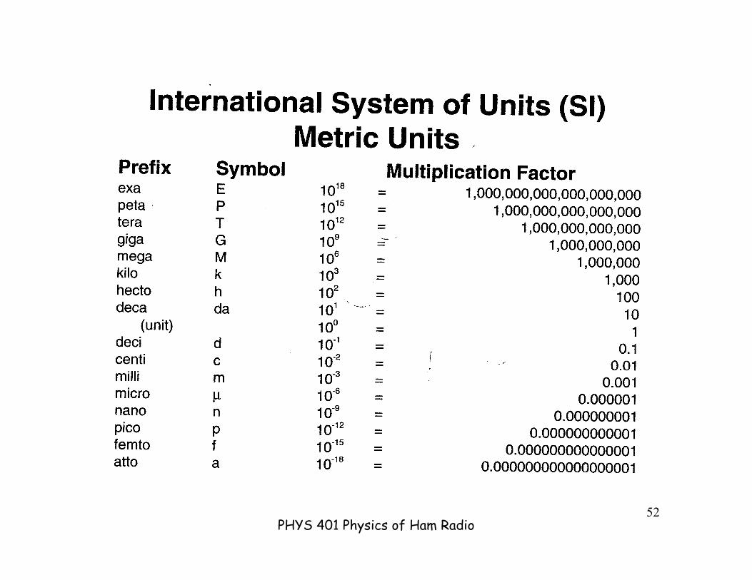
PHYS 401 Physics of Ham Radio52

PHYS 401 Physics of Ham Radio53

PHYS 401 Physics of Ham Radio54
Amplifiers• Tubes and transistors
amplify signals applied tobase or control grid.
• Transistors haveadvantages:
• size• power consumption• cooling• robustness
• Tubes have advantages:• high power

PHYS 401 Physics of Ham Radio55
Test Equipment• Voltmeter - an instrument that is used to measure voltage.
– It is used in parallel with a circuit to be measured.– a series resistor extends the range of the meter.
• Ammeter - an instrument used to measure amperage in a circuit.– It is hooked up in series with the circuit to be tested.– A shunt resistor (in parallel w/meter) extends the range of the meter.
• Multimeter - combines the functions above with resistance andothers to make a versatile piece of test equipment.
• Wattmeter - a device that measures power coming from atransmitter through the antenna feed line. A directionalwattmeter measures forward and reflected power. Wattmetersgenerally are useful in certain frequency ranges
• Signal Generator - a device that produces a stable, adjustable lowlevel signal (AF or RF). It can be used to tune circuits.


