Basic Electronics Part 5 - the-eye.euthe-eye.eu/public/Books/Electronic...
109
Transcript of Basic Electronics Part 5 - the-eye.euthe-eye.eu/public/Books/Electronic...


BASIC ELECTRONICS
Part 5
A Course of Training Developed for
THE UNITED STATES NAVYby the New York firm of
gement Consultants and Graphiological Engineers
S^ALKENBURGH, NOOGER & NEVILLE, INC.
(CENTRAL!1
T
'1RAHXJ
pted to J3r» and Commonwealth Usage
Special F i Training Investigation Team of
the Roy al & Mechanical EngigSj$£ 3?J
^ mm
LONDON
iHE TECHNICAL PRESS, LTDNEW YORK
THE BROLET PRESS

British and Commonwealth Edition first published 1959
©Copyright 1959 by
VAN VALKENBURGH, NOOGER & NEVILLE, INC.New York, U.S.A.
All rights reserved
American Edition first published 1955
©Copyright 1955 by
VAN VALKENBURGH, NOOGER & NEVILLE, INC.
New York, U.S.A.
U.S. Library of Congress Catalog Card No. 55-6984
All rights reserved
.'.'JAN
&rar;es
76/32. t
Made and printed by Offset in Great Britain by
William Clowes and Sons, Limited, London and Beccles

PREFACE
IN THESE six Manuals on BASIC ELECTRONICS and the five which have pre-
ceded them on BASIC ELECTRICITY, there lies the core of an illustrated
Course of Technician Training—carefully planned, brilliantly simplified, and radi-
cally new—which was developed some years ago at the request of the United States
Navy by a distinguished New York firm of management consultants and graphio-logical engineers, Messrs. VAN VALKENBURGH, NOOGER & NEVILLE, INC.The Course has since become standard in U.S. Navy Training Schools. More than50,000 men have taken it as an essential part of their training to technician level in
14 different Navy trades; their average training time has been cut by half; andsupplies of Course materials are now held as part of the Navy's official War Mobiliza-tion Stores.
The text of the Course was subsequently released in a condensed form to the
general public in the United States, where it has proved an outstanding success. In
addition to large sales to individuals, to schools and to technical institutions of all
kinds, more than a score of world-famous companies have taken the published
Manuals for use in their Apprentice Training Schemes, and have found that they
enable them to turn out qualified technicians both faster and at less cost than did
the old methods of text-book and lecture. Several American trade unions (who take
a keen interest in the "up-grading" of their members to more skilled and better-paid
jobs) have chosen the Manuals as the best available training materials for their
purpose.
This notable Series is now being made available, in a revised, reset, and suitably
re-worded edition, to users in Britain and the Commonwealth.
While negotiations with the American authors were still in progress, word reached
the British publishers that there had recently been set up, under command of Train-
ing Headquarters, Royal Electrical and Mechanical Engineers, at Arborfield in
Berkshire, a special "Electronics Training Investigation Team" whose task was to
devise solutions for some of the training problems which would face the British
Army when National Service ended, and when the Army's increasingly elaborate
electrical and electronics gear would have to be manned and serviced by recruits
entering the Army with none of the technical knowledge which many National
Servicemen had hitherto brought with them into the Forces.
It seemed possible that most of the REME requirements for a new-style, yet
technically sound, instructional approach could be met by a suitably edited British
version of the VVN&N Manuals. A visit to Arborfield was accordingly arranged,
where the reception given to the Manuals, with their attractive appearance andproved record of success, was enthusiastic; and after a careful evaluation of their
merits and potential suitability had been made, War Office consent was secured to
a proposal that the work of adapting text and illustrations to British notation andterminology should be undertaken by the Electronics Team at Arborfield.
Later, while this work was still proceeding, a decision was reached to adopt the
revised Manuals as basic texts for the training of future REME technicians, and anorder for large numbers of complete sets of the Manuals was placed. Early interest

was also shown by several other branches of the Armed Forces, notably the Royal
Corps of Signals and the Royal Air Force. Military Advisers to the High Com-missioners of at least six leading Member Nations of the Commonwealth submitted
early proofs of the English edition to their respective Ministries of Defence.
The original U.S. Navy Course was based on a novel technique of teaching
developed by the Authors after extensive research and practical experience with
thousands of students. Immense pains were taken to identify and present only the
essential facts about each new concept or piece of equipment. These facts were
then explained in the simplest possible language, one at a time; and each was illus-
trated by a cartoon-type drawing. Nearly every page in every one of the Manuals
carries one or more of these brilliantly simple "visualizations" of the concept
described.
The approach throughout is non-mathematical. Only the simplest equations
needed for working with the fundamental laws of electricity are employed. Yet
there has been no shirking of essentials, even when they are difficult; and students
with higher qualifications and educational background find nothing in the Manuals
to irritate or slow them down. They merely pass on to the next subject quicker
than the rest.
Despite their Services background, the Manuals have been proved suitable for
civilian use. Their purpose, however, is limited to the training of technicians, not
of engineers. They aim to turn out men capable of operating, maintaining, and
carrying out routine repairs to the equipment described—not men capable of invent-
ing or improving it.
They present a unique simplification of an ordinarily complex set of subjects—so
planned, written and illustrated as to become the best and quickest way to teach or
learn BASIC ELECTRICITY and BASIC ELECTRONICS that has ever been
devised.
In these Manuals, first things come first—and only the essentials come anywhere.
Their accuracy and thoroughness, combined with their extreme lucidity, will maketheir publication a landmark in technical education in Britain and the Common-wealth.

TABLE OF CONTENTS
Sectionpage
1 Introduction to Receivers 5 j
2 Receiver Aerials5 13
3 TRF Receivers—R.F. Amplifier Stage 5.21
4 TRF Receivers—Detector Stage 5 29
5 TRF Receivers—Audio Amplifier Stage 5.38
6 The Superheterodyne Receiver 5 43
7 Fault-finding5 j^
8 General Review of Receivers 5 92
9 Miscellaneous Electronic Circuits 5 95
10 Frequency Modulation : Transistors 5. 100
Index5J01

This Course in
BASIC ELECTRONICS
comprises 6 Parts
This is PART 5
It is preceded by a Course in
BASIC ELECTRICITY
comprising 5 Parts
all uniform with this volume.
Part 1 explained the General Principles of Electricity.
Part 2 described and discussed D.C. and D.C. Circuits.
Parts 3 and 4 described and discussed A.C. and A.C. Circuits.
Part 5 described and discussed A.C. and D.C. Machines.
BASIC ELECTRONICS
will be followed by a further Course in
BASIC SYNCHROS & SERYOMECHANISMS
in two Parts
also uniform with this volume

§ I: INTRODUCTION TO RECEIVERS 5.1
The History of Communications
Since the earliest days, Man has always tried to increase the distance over whichhe could send messages. The modern radio transmitter and receiver are merely
the latest and most efficient of a long series of devices which he has invented anddeveloped to the same end.

5.2 [§|
The History of Communications {continued)
Some of the more primitive methods of communication—human messengers andhoming pigeons, for instance—today have only limited application.
But we still use semaphore signals and interrupted flashes of light to conveymessages. Coloured lights, rockets and flares are only more up-to-date versions of
those warning hilltop fires which flashed news of the coming of the Spanish Armadaacross the length and breadth of England—from Plymouth to "the burghers of
Carlisle." Whistles and sirens are still used in ways differing only in degree fromthe uses to which they were put in the days of the Roman Empire.
SOME JJJDUilJj/] VERSIONS OF
rJiJJJJ J J J J£ METHODS ARE
Signal lamps
Sirens

§'1 5.3
The History of Communications (continued)
These simple signalling systems, however, are at best slow and unreliable. If the
wind is blowing from the wrong direction, sound signals may not be received. In
thick fog or heavy rain, visual signals fail to deliver their message. Runners and
pigeons are slightly more reliable; but their rate of travel is relatively slow.
The problem of rapid and reliable communication was only finally solved by
harnessing electricity to the task.
Improvements on the inventions of Morse, Bell and Marconi have led to the
development of modern telegraph, telephone and wireless communication systems
which are capable of transmitting messages almost instantaneously over thousands
of miles.
tfl*^DE COMMUTATIONSR^^^

5.4
The History of Communications (continued)
B
tSSCOMMUN.c^,^
Transmission by telephone and telegraph is, of course, still limited to placeswhich can be physically reached by a wire or cable; but with the advent of "wire-less" communication (or, as it is more commonly called, radio communication) theuse of electricity for transmitting messages has reached its most advanced stage.
This remarkable electronic system, radio, consists of two parts—the transmitterand the receiver. The transmitter, as you learnt in Part 4 of Basic Electronics,sends out the message in the form of radio waves. The radio receiver picks upthese radio waves, and converts them into the message which was originally put intothe transmitter.
This Part of Basic Electronics deals with the receiving end of radio communica-tion—the receiver.

§1]
The Jobs a Receiver Performs
5.5
The jobs which a receiver must perform are very much the same in radio, in
television, in radar and in echo-sounding equipment. Both the type of signal goinginto the receiver and the type of signal coming out of the receiver are different for
each type of equipment; but the stages which an incoming signal must go throughbefore it emerges as a useful output are almost identical whether the receiver is used
for radio, television, radar or echo-sounding.
The function of any receiver can be broken down into five separate steps, as
follows:
1 . Picking up incoming signals. In radio, television and radar, the incoming signals
are electro-magnetic carrier waves sent out by a transmitter. When these wavescut across the receiving aerial, a very weak current is caused to flow in the aerial.
This current varies in frequency and in amplitude in such a way as to duplicate
the signal radiated from the transmitter aerial.
In echo-sounding equipment, the "aerial" is an underwater microphone which^converts the incoming signal to a weak current flow, and so serves the samepurpose as the radio and radar aerials.
RADIO
MODULATEDCARRIER WAVE
UNDERWATER <2%t+*MICROPHONE A# ""-
m,^mm RADAR ECHO —
Selecting the desired signal. Manytransmitters are sending out sig-
nals which reach a receiver aerial,
however; and of these manysignals, the receiver must be able
to select the one desired. Every
transmitter uses a different fre-
quency, while the receiver contains
circuits which can be tuned to
any frequency the operator desires
to receive.
By tuning these circuits to the
frequency of the signal of one of
the transmitters, you can select that
desired signal and reject all others.
The more tuned-circuits used in a
receiver, the sharper is the tuning
of that receiver.

5.6 [§l
The Jobs a Receiver Performs (continued)
3. Amplifying the desired r.f. signal. The currents generated by the incoming
signals in the aerial are extremely weak. R.F. amplifiers similar to those you
have already studied are used to amplify these weak signals before they reach
the detector.
4. Detecting, or demodulating, the amplified signal. A detector stage follows the
last r.f. amplifier in a receiver. The detector does the important job of separat-
ing the "envelope" of the signal from the r.f. carrier. Because the envelope is
the modulation of the signal, a detector is sometimes called a "demodulator."
The signal, after demodulation, may be either a voice or code signal, as in
communications radio receivers; or else a rapid change of voltage, as in radar
or television receivers.
5. Amplifying the audio or video signals. In radio receivers, the audio signal
which comes from the detector undergoes further amplification. Audio voltage
amplifiers and power amplifiers similar to those you have already studied build
up the audio signal to a sufficient strength to operate a pair of earphones or a
loudspeaker, so that the signal may be heard.
In radar receivers, the signal will show up as a "pip" on an oscilloscope. In
these receivers, video amplifiers similar to those you have already learnt about
are then used to amplify the voltage "pips." The video amplifiers take the
signal from the detector, and build it up so that it can be seen on the radar screen.
AA
f1
2
TunedCircuit
COMMUNICATIONTYPE
RECEIVER
4 5
DetectorAudioAmp.
4—
¥
-H-Ajv JU RADAR
TYPERECEIVER
Y2 3 4 5
TunedCircuit
RFAmp. Detector
VideoAmp.

§ I]5 -7
Receiver Sensitivity
There are several characteristics of a receiver which can be determined simply
by comparing the receiver output with the input signal. These characteristics will
tell you how well your receiver is working.
The first of the characteristics—there are three in all—is sensitivity.
Sensitivity can be defined as the ability of a receiver to pick up weak signals, to
amplify them, and to deliver a useful output. No matter what type of equipment
the receiver is in, sensitivity is important because many input signals which the
receiver must amplify are extremely weak. And only a sensitive receiver can
develop a sizable output from a weak input.
Receiver Not Sensitive Enough
HI-YO
Very Sensitive Receiver

[§l5.8
Receiver Selectivity
Sensitivity by itself, however, will not make a receiver good enough for use. It
must also be selective.
Selectivity may be defined as the ability of a receiver to select a desired signal,
and to discriminate against all undesired signals.
Even if every signal which reached the aerial was amplified, the output—althoughstrong enough—would still be useless because of all the interference caused by thepresence of the unwanted signals.
M,#*fr$ny*R
y£& moon *„
Selective Receiver

Si] 5 -9
Receiver Fidelity
If the receiver can pick out one signal from the many which reach the aerial
(selectivity), and can amplify it so as to produce a useful output even though the
signal may be weak (sensitivity), the receiver is good enough to be used in quite
a number of applications.
For other applications, however, one more thing is important—the receiver must
be able to reproduce the original signal without distortion. A receiver which can
do this is said to have good fidelity; a receiver which cannot has "poor fidelity."
Home radio receivers usually have good fidelity, because they are made for the
enjoyment of the listener. Communications receivers are made to reproduce speech,
but only so that it shall be intelligible; they are therefore not usually designed with
good fidelity in mind.
Radar receivers, on the other hand, must have good fidelity because the operator
can get a great deal of information from the exact appearance of the received
signal as it is displayed on his oscilloscope.

5.10[§ |
The Crystal Receiver
The first receivers used in the early 1900s were called "crystal sets." In their
simplest form they consisted of an aerial, a tuned-circuit, a crystal detector, and a
pair of earphones.
The aerial picked up any signals there might be about—in those days there werevery few of them!—and the tuned-circuit selected the wanted one. The crystal
—
usually a piece of galena or carborundum with a "cat's whisker" contact device
—
"detected" the signal in a manner you will learn about later. The resulting audio-frequency signals were then used to energise the earphones.
Simple though these crystal sets were, a fair degree of skill was needed in the
adjustment of the "cat's whisker"; and, since their sensitivity was poor, consistently
good results could only be obtained in the neighbourhood of the transmitter.
Today these wireless sets are curiosities—but the crystal detector is used in manymodern equipments.
IN THE BEGINNING...
§1]
The TRF Receiver
5.11
RF AMPLIFIER DETECTOR AUDIO AMPLIFIER
By 1920 crystal sets were on their way out, and were being replaced by tuned
radio frequency (TRF) receivers which made use of valves.
The first one or two valves, and their tuned-circuits, make up the r.f. amplifier
which gives the TRF receiver better selectivity and sensitivity than had the old
crystal sets. The detector does the same thing as did the crystal detector, but
sometimes amplifies the signal as well.
After the detector, the audio signal is amplified in the audio amplifier. The
output of this audio amplifier is a fairly powerful signal, which can be used to
drive a loudspeaker or a pair of earphones.
TRF receivers are not very often used today, but some receivers are still of
this type.
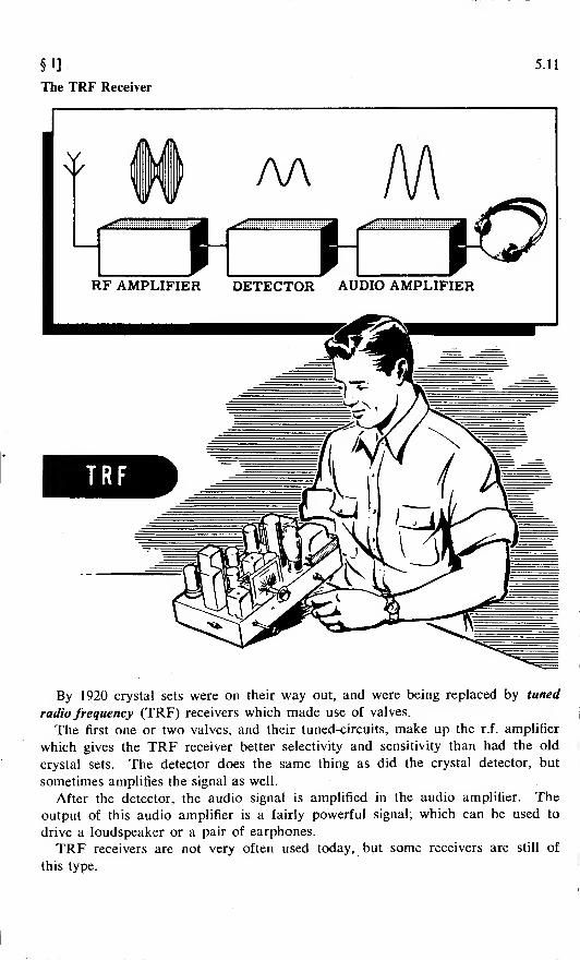
[§l5.12
The Superheterodyne Receiver
The most common type of receiver used in home radios and in other equipmenttoday is the superheterodyne receiver.
In this type of receiver, not all the r.f. amplification takes place at the incomingsignal frequency. Most of it is achieved after the incoming signal has been con-verted to an intermediate frequency (i.f.), which is always the same no matter whatthe frequency of the desired signal may be.
LocalOscillator
Detector AFAmplifier
SUPERHET
The only parts in a superhet which are additional to those in a TRF are thevariable-frequency local oscillator, the mixer and the i.f. amplifier. >
The variable-frequency local oscillator is similar to the oscillators which youhave already studied. The oscillator produces an r.f. signal which is "mixed" inthe mixer stage with the signal from the r.f. amplifier. The resulting i.f. frequencyis the difference between the input signal frequency and the local oscillatorfrequency.
The i.f. is a fixed frequency, and the i.f. amplifiers are therefore fixed-tuned.This allows them to be very accurately tuned, so that high gain and selectivity canbe obtained at the chosen frequency.
You will find out exactly how a superhet receiver works later in this Part. Forthe time being, it is enough for you to know that the advantage of the superhetover the TRF receiver is that the superhet has higher gain and greater selectivity.

§2: RECEIVER AERIALS 5.13
The Function of Receiver Aerials
The purpose of the receiver aerial is to intercept the electro-magnetic wavesradiated from the transmitter. When these waves cut across the aerial, they gener-ate a small voltage in it. This voltage causes a weak current to flow in theaerial-earth system.
This feeble current has the same frequency as the current in the transmitter. If
the original current in the transmitter is amplitude-modulated, the aerial currentwill vary in exactly the same manner.
This weak aerial current, flowing through the aerial coil, induces a correspond-ing signal voltage in the grid circuit of the first r.f. amplifier stage of the receiver.
Electromagnetic Waves
nWHCurrent
TRANSMITTER
VCurrent
RECEIVER
RECEIVER AERIALS INTERCEPT THE RADIO WAVES SENT OUT BYTHE TRANSMITTER
A receiving aerial should feed as much signal, and as little undesired interference,
to the receiver as possible. It should be constructed so that the signal is not lost
or dissipated before reaching the receiver. It should give maximum response atthe frequency or band of frequencies to which the receiver is tuned.
An aerial can also be "directional," which means that it will give best responsein the direction from which the operator wishes to receive.
The receiver aerial problem is easily solved when the receiver is operated inconjunction with a transmitter. Since the transmitting aerial is usually designedto incorporate the desirable features which have just been listed, the same aerialcan be used alternately for both transmitter and receiver.
A switch or relay is used to connect the aerial to whichever piece of equipmentis operating at any particular moment.However, wireless stations are frequently receiving-stations only; and it is then
necessary to erect a separate receiving aerial, paying attention to the four considera-tions of noise, signal loss, frequency response and directivity.
Before discussing these considerations of aerial design, you should get to knowsomething about a few of the more common types of receiving aerials.

5.14 [§2
Types of Receiver Aerials
One of the simplest and most commonly used aerials is the "inverted L." It
consists of a wire, known as a "flat-top," which is suspended horizontally between
two insulators.
The length of the wire should be from 50 to 75 feet for medium broadcast-band
reception, and from 20 to 40 feet for high frequency reception. The flat-top should
be suspended from 30 to 50 feet above ground.
A wire known as the "lead-in" is used as a transmission line from the aerial to
the receiver. It is connected near one end of the flat-top, and brought down to the
primary winding of the receiver aerial coil.
Flat-top
INVERTED L AERIAL
Another common type of aerial is the "doublet," or dipole aerial. It consists
of a horizontal wire divided into two equal sections by an insulator.
Each half of the aerial should ideally be a quarter-wavelength long, for the
frequency most commonly used.
The transmission line from the aerial is connected to the two ends of the primary
of the aerial coil.
This type of aerial will give excellent high-frequency reception, and will also give
comparatively noise-free reception on the broadcast band.
It may be of interest to note that most of the television receiver aerials with
whose appearance you are so familiar are little more than modifications of the
dipole aerial, with metal bars replacing the less rigid wires.
1/4 wavelength
i—eCUO-
1/4 wavelength
!~«JA
^
Transmissiony^\Line
DIPOLE AERIAL

§2]
Types of Receiver Aerials (continued)
5.15
Where lack of space makes horizontal
aerials impracticable, a vertical aerial is
used instead.
Vertical aerials, consisting of tele-
scoping metal masts from 3 to 14 feet in
length, are commonly used for cars and
portable receivers, and sometimes for
home broadcast receivers.
An ordinary lead-in wire is run from
the bottom of the aerial to the primary
of the aerial coil of the receiver. The
other end of the primary should be
earthed.
VERTICALAERIAL
Another type of aerial used for port-
able and home receivers is the "frame
aerial."
The aerial consists of a coil of wire
which is connected to the two ends of
the primary of the aerial coil. Manyportable broadcast-band receivers con-
tain a frame aerial within the cabinet.
The frame aerial is highly directional.
When it is pointed edgeways towards
a transmitter, the signal pick-up is
maximum; when its flat side is towards
the transmitter, the signal pick-up is
minimum. This property makes it ex-
tremely useful for radio-beacon and
direction-finding equipment.
When used in conjunction with
direction-finding equipment, the frame
aerial takes the form of a loop, and is
therefore called a "loop aerial."

5.16 .[§2
Selecting and Installing an Aerial—Noise
An important consideration in aerial installation is that of undesired radio noise(commonly called simply "noise").
Noise consists of radio waves of many frequencies, and is produced by bothman-made and natural electrical disturbances. Among the more important man-made noise producers are lifts, fans, refrigerators, vehicle ignition systems, vacuumcleaners, X-ray and diathermy equipment, and mains power lines.
No aerial can differentiate between desired signals and undesired radio noise,though steps can be taken to minimize the latter.
It is customary to compare the signal pick-up of the aerial with its noisepick-up. This relationship is known as the "signal-to-noise ratio."
A high signal-to-noise ratio is necessary for relatively noise-free reception.
DesiredSignal
WavesNOISE WAVES
AERIALS CANNOT DIFFERENTIATE BETWEEN SIGNALAND NOISE RECEIVER
NoisyReception

§2]*•»
Selecting and Installing an Aerial—Noise (continued)
There are various ways in which a high signal-to-noise ratio may be obtained.
The first is by locating the aerial as far as possible from power lines, and any
other electrical devices likely to produce noise.
Placing the aerial at right angles to the mains power lines will also reduce the
amount of noise.
HIGH SIGNAL-TO-NOISERATIO (Low Noise Pickup
LOW SIGNAL-TO-NOISE RATIO(Hi£h Noise Pickup)
The second method is by increasing the height above ground of the aerial as much
as practical considerations will allow. This tends to increase the signal strength,
and to reduce the amount of noise.
The third method involves using a good earth connection to the receiver when
provision is made for one. A poor earth lead may pick up noise; it should there-
fore be kept as short as possible, and away from noise-producing devices.
A good eartrrlead should use rubber-insulated wire, S.W.G. No. 16, or copper
braid. It should make good contact through a clamp to an earthed object, such as a
radiator or water pipe. Gas pipes should never be used for earthing purposes.
A good deal of noise may be picked up by the lead-in. If the lead-in uses two
wires, as in the case of the transmission line used with a dipole aerial, noise can be
reduced by using twisted wires, or by reversing the positions of the wires every
few feet.
Noise can also be reduced by using screened lead-in wires.
518 B 2
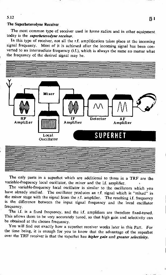
Selecting and Installing an Aerial—Signal Losses
The second factor to be considered in selecting and installing an aerial is thatof signal losses.
The aerial should be placed as far as possible from metal objects, chimneys,walls, and tree branches. These objects absorb radio waves, and thus reduce thestrength of the signal reaching the aerial.
A loose or swinging aerial may cause the signal to fade.
FACTORS THAT CAUSEAERIAL SIGNAL LOSSES. .
.
^r-
Aerial touchingtree branches
Aerial sur-rounded by tall buildings
Aerial swaying in the breeze
Signal losses will also be increased if a high resistance is present in the aerialcircuit. To reduce resistance, all joints and connections should be carefullysoldered; and, where possible, the aerial and lead-in should consist of a single pieceof wire with no joints.
Signal losses may be further increased by leakage of current through poor sup-porting insulators. Insulators should be made of materials such as glazed porce-lain or pyrex glass, which do not readily absorb moisture and thus provide a leakagepath for current.
Aerial Wire
Insulator
Lead-in
sant=
Tie-Wire
REDUCING AERIAL RESIST-ANCE BY ELIMINATING JOINTS

§2]5.19
Selecting and Installing an Aerial—Frequency Response and Directivity
The third consideration is that of frequency response, which is related to the aerial
length. A maximum signal, at a given frequency, will be induced in the aerial if
its length is either one-quarter or one-half the wavelength of the signal to be
received.
It is possible to change the effective length of an aerial by placing a coil or a
capacitor in series with it. Adding inductance increases the electrical length of the
aerial; while adding capacitance shortens it.
The front panel of certain receivers contains a control marked ae. tune (aerial
tuning). This control varies the size of a small capacitor, and is used to compen-
sate for variations in aerial length.
In general, however, adjustment of the aerial to the correct length is not nearly
as important for receiving equipment as it is for transmitters.
The final consideration is that of directivity. All aerials, except the vertical
type consisting of a single perpendicular wire, have directional properties, and
receive signals from certain directions better than they do from others.
A horizontal or inverted L aerial will receive best when the signal cuts the aerial
wire at right angles. For any one station, of course, the aerial may be turned so
that it produces the maximum signal pick-up. But since it is extremely unlikely
that all transmitters will be broadcasting from the same direction, the position of
the aerial will usually have to be a compromise for all stations.
Dipole aerials may be made highly directional by arranging them into systems
called "arrays," similar to those employed with television systems.
FACTORS TO BE CONSIDERED IN
SELECTING AND INSTALLINGAERIALS . .
5.20
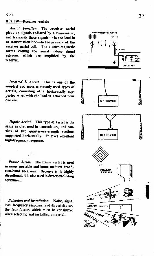
REVIEW—Receiver Aerials
Aerial Function. The receiver aerial
picks up signals radiated by a transmitter,
and transmits these signals—via the lead-in
or transmission line—to the primary of the
receiver aerial coil. The electro-magnetic
waves cutting the aerial induce signal
voltages, which are amplified by the
receiver.
[§2
Electromagnetic Waves
Hill Illli
Inverted L Aerial. This is one of the
simplest and most commonly-used types of
aerials, consisting of a horizontally sup-
ported wire, with the lead-in attached near
one end. RECEIVER
Dipole Aerial. This type of aerial is the
same as that used in transmitters, and con-
sists of two quarter-wavelength sections
supported horizontally. It gives excellent
high-frequency response.
Frame Aerial. The frame aerial is used
in many portable and home medium broad-
cast-band receivers. Because it is highly
directional, it is also used in direction-finding
equipment.
Selection and Installation. Noise, signal
loss, frequency response, and directivity are
the four factors which must be considered
when selecting and installing an aerial.
-•-<ca>p-
RECEIVER
TT*
\
§3: TRF RECEIVERS-R.F. AMPLIFIER STAGE 5.21
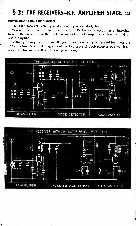
Introduction to the TRF Receiver
The TRF receiver is the type of receiver you will study first.
You will recall from the first Section of this Part of Basic Electronics, "Introduc-
tion to Receivers," that the TRF consists of an r.f. amplifier, a detector, and anaudio amplifier.
So that you may have in mind the goal towards which you are working, there are
shown below the circuit diagrams of the two types of TRF receiver you will learn
about in this and the three following Sections.
TRF RECEIVER WITH A DIODE DETECTOR

5.22' B 3
The R.F. Amplifier Stage
Every TRF receiver contains one or more stages of r.f. amplification preceding
the detector. The main purpose of these amplifiers is to provide additional selec-
tivity and sensitivity.
You will recall that selectivity indicates how well a receiver receives a desired
signal and rejects unwanted signals; and that sensitivity is a measure of the re-
ceiver's ability to pick up a weak signal. Up to a point, the more r.f. amplifier
stages there are in an equipment, the greater will be its selectivity and sensitivity.
Let us now briefly review some of the principal points you have learnt about r.f.
amplifiers.
VAerial
GREATER SELECTIVITY AND SENSITIVITYOBTAINED BY USING MORE TUNED
RF STAGES
1STRF
AMPLIFIER
2NDRF
AMPLIFIER
3RDRF
AMPLIFIER
* Since the r.f. amplifier stage is designed primarily for voltage amplification, any
valve suitable for voltage amplification may theoretically be used. But in practice
triodes are not considered satisfactory, because they have a strong tendency to
produce undesirable oscillations when employed in r.f. amplifier stages. Unless
the triodes are carefully neutralized to prevent feedback, these oscillations are likely
to cause trouble.
Valves containing a screen grid do not suffer from this disadvantage; and for
this reason most r.f. amplifiers used in receivers employ either tetrodes or pentodes.
The valve which is generally preferred as an r.f. amplifier is a variable-mu pen-
tode. This type of valve not only provides considerable voltage gain, but also
minimizes certain types of interference from powerful undesired signals. Since
varying the grid bias of a variable-mu pentode changes the amount of amplification,
this type of valve is very suitable for use in circuits involving either manual or
automatic gain (volume) control
Only screen grid
valves are usedin receiver RFamplifiers
Yet even when pentodes are used in r.f. amplifiers, the number of stages of
amplification is limited because of a tendency towards instability caused by inter-
action between the stages, which can cause oscillations. You will therefore rarely
meet r.f. amplifiers containing more than two stages.
§3]
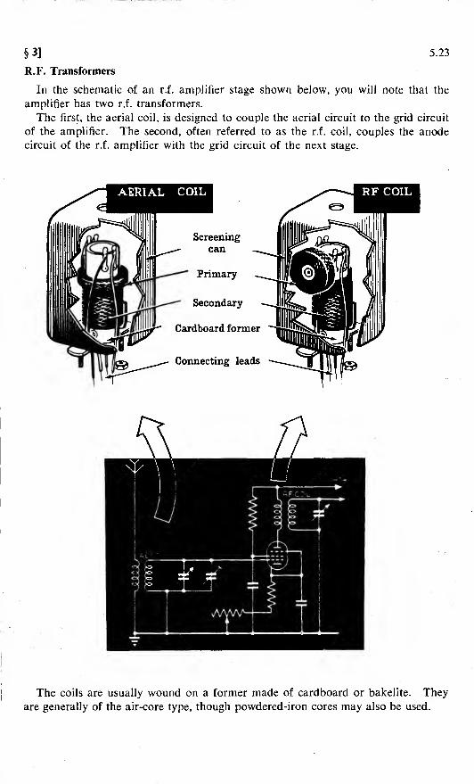
R.F. Transformers
5.23
In the schematic of an r.f. amplifier stage shown below, you will note that the
amplifier has two r.f. transformers.
The first, the aerial coil, is designed to couple the aerial circuit to the grid circuit
of the amplifier. The second, often referred to as the r.f. coil, couples the anode
circuit of the r.f. amplifier with the grid circuit of the next stage.
The coils are usually wound on a former made of cardboard or bakelite. They
are generally of the air-core type, though powdered-iron cores may also be used.
5.24 [§3
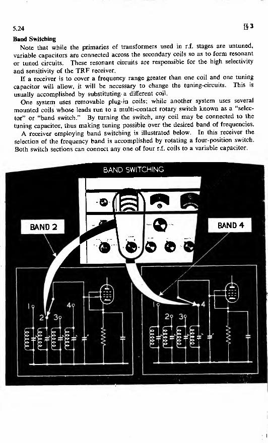
Band Switching
Note that while the primaries of transformers used in r.f. stages are untuned,
variable capacitors are connected across the secondary coils so as to form resonant
or tuned circuits. These resonant circuits are responsible for the high selectivity
and sensitivity of the TRF receiver.
If a receiver is to cover a frequency range greater than one coil and one tuning
capacitor will allow, it will be necessary to change the tuning-circuits. This is
usually accomplished by substituting- a different coil.
One system uses removable plug-in coils; while another system uses several
mounted coils whose leads run to a multi-contact rotary switch known as a "selec-
tor" or "band switch." By turning the switch, any coil may be connected to the
tuning capacitor, thus making tuning possible over the desired band of frequencies.
A receiver employing band switching is illustrated below. In this receiver the
selection of the frequency band is accomplished by rotating a four-position switch.
Both switch sections can connect any one of four r.f. coils to a variable capacitor.

§3]5.25
Ganged Capacitors
Every TRF receiver has a minimum of two tuned-circuits, one associated with
the r.f. amplifier and one with the detector.
In the early days of the TRF, every variable capacitor was connected to its own
individual tuning knob. In order to tune your radio to a station, you had to turn
each knob individually until each tuned-circuit was resonant at the frequency of
the desired station.
The later TRF receiver eliminated the need for individual tuning knobs by having
the variable capacitors of all the tuned-circuits mounted on one shaft. This allowed
the receiver to be tuned with a single control, which varied all the tuned-circuits
together and at the same time.
This is called "ganged" tuning. In a receiver having two r.f. amplifier stages,
plus a detector, a three-gang capacitor would be used.
Since all the tuned-circuits are varied together, all the variable capacitors should
have exactly equal capacitances at every setting of the gang spindle. All the tuned-
circuits would then be resonant at the same frequency at the same time—resulting
in maximum sensitivity and selectivity.
Unfortunately, no two capacitors can be manufactured exactly alike; so the
individual capacitor sections on a ganged unit will have slightly different capaci-
tances at every setting. If nothing were done to compensate for these differences
in capacitance, the tuned-circuits in a receiver would be resonant at slightly differ-
ent frequencies for every setting of the tuning knob—causing poor receiver selectivity
and sensitivity.
A receiver with such characteristics is said to be "out of alignment."
A = 200 pF
B= 195 pF
C=204pF
RESONANTTO 600 Kc/S
RESONANTTO 603 KQ/s
I3RD
RF
RESONANTTO 598 Kc/s
RECEIVER OUT OF ALIGNMENT

[§35.26
Trimmer Capacitors and Coils
The problem of misalignment can be solved by adding small variable capacitors,
called "trimmer capacitors," in parallel with the main variable tuning capacitors.
Sometimes the adjustment is made in the coil of a tuned-circuit, rather than onthe capacitors. In this case, an iron-cored slug is moved in and out of the coil,
causing the inductance to vary. This is called "permeability," or "slug tuning."In receivers covering only one band, the trimmers are usually located on the
ganged capacitors, one for each section. In receivers using band switching, thetrimmers for each range are usually mounted on, and in parallel with, the individualcoils.
These trimmer capacitors are adjusted after the main capacitors have been set
at minimum capacitance at the high end of the dial. They are adjusted to makethe total capacitance of the individual tuned-circuits the same at every setting ofthe tuning control.
The tuned-circuits will therefore be tuned to the same frequency, simultaneously,over the whole width of the band—the result being high receiver sensitivity andselectivity.
VARIABLECAPACITORS
RESONANTTO 600 Ke/s
RESONANTTO 600 Kc/s
RESONANTTO 600 Kc/S
RECEIVER IN ALIGNMENT
It sometimes happens that, although the circuits are properly adjusted at the highend of the dial, they do not tune to identical frequencies at the other end of thedial. A correction may be made for this, in some sets, if the end rotor plates areof the slotted type. Adjustments can be made by bending a portion of the slotted
plates either towards, or away from, the stator plates.
When all of the ganged circuits of a TRF receiver tune to the same frequency at
any particular dial setting, they are said to be "tracking," and the receiver is in
alignment.
§3]
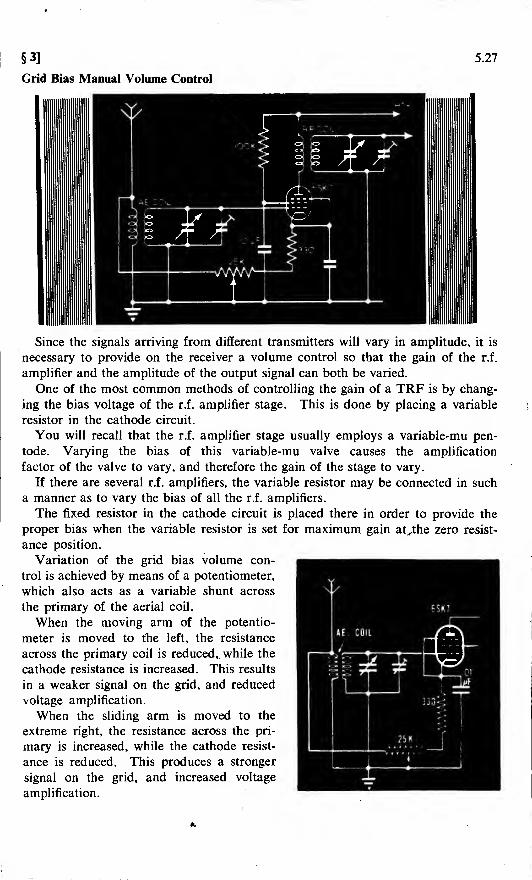
Grid Bias Manual Volume Control
5.27
Since the signals arriving from different transmitters will vary in amplitude, it is
necessary to provide on the receiver a volume control so that the gain of the r.f.
amplifier and the amplitude of the output signal can both be varied.
One of the most common methods of controlling the gain of a TRF is by chang-
ing the bias voltage of the r.f. amplifier stage. This is done by placing a variable
resistor in the cathode circuit.
You will recall that the r.f. amplifier stage usually employs a variable-mu pen-
tode. Varying the bias of this variable-mu valve causes the amplification
factor of the valve to vary, and therefore the gain of the stage to vary.
If there are several r.f. amplifiers, the variable resistor may be connected in such
a manner as to vary the bias of all the r.f. amplifiers.
The fixed resistor in the cathode circuit is placed there in order to provide the
proper bias when the variable resistor is set for maximum gain at^the zero resist-
ance position.
Variation of the grid bias volume con-
trol is achieved by means of a potentiometer,
which also acts as a variable shunt across
the primary of the aerial coil.
When the moving arm of the potentio-
meter is moved to the left, the resistance
across the primary coil is reduced, while the
cathode resistance is increased. This results
in a weaker signal on the grid, and reduced
voltage amplification.
When the sliding arm is moved to the
extreme right, the resistance across the pri-
mary is increased, while the cathode resist-
ance is reduced. This produces a stronger
signal on the grid, and increased voltage
amplification.

5.28
REVIEW—R.F. Amplifier Circuit
[§3
Now pause for a moment to examine the r.f. amplifier shown above, and to review
the purpose of each of its components.
The aerial coil couples the aerial to the control grid of the r.f. amplifier. Thevariable capacitor enables the operator to tune the amplifier to the frequency of the
desired signal, and thus provides selectivity. The 25-K variable resistor acts as a volumecontrol; while the 330-ohm resistor sets the lower limit of cathode bias. Thecapacitor between the cathode and earth is the bypass capacitor.
The 100-K resistor in the screen grid circuit is the screen grid voltage dropping resistor,
which serves to keep the screen grid at a lower positive potential than the anode. The0*01-(xF capacitor in the screen grid circuit is the screen grid decoupling capacitor,
which acts as a bypass for r.f. signals and enables the screen to act as a shield betweenthe anode and the control grid.
The r.f. coil in the anode circuit acts as the anode load. The secondary of this r.f.
coil is connected into the next stage.

§4: TRF RECEIVERS-DETECTOR STAGE 5.29
What the Detector Does
The primary purpose of the detector circuit is to change the r.f. signal into a
signal which can be reproduced as sound by the headphones or loudspeaker. With-
out the detector, radio reception is not possible.
The simplest radio receiver, reduced to its bare essentials, would consist of a
detector, an aerial, and a pair of headphones. All other stages which are found in
front of the detector in more complex receivers, such as the TRF or the "superhet,"
have been put there for the primary purpose of enabling the detector to do a
better job.
In order to understand the purpose of the detector, it is necessary to review briefly
the theory of radio-telephony transmission.
In Part 4 of Basic Electronics, which dealt with radio transmitters, you learnt
that radio-telephony transmission requires the generation of a radio-frequency
carrier wave. Intelligence is impressed on this wave, one method of doing so being
to vary the amplitude of the carrier wave.
A combination of audio-frequency waves superimposed on a carrier wave is
known as an amplitude-modulated signal; and it is this combination of waves whichis picked up by the aerial of the radio receiver.
When transmitted signals reach a receiver, the desired signal is selected by tuned-
circuits. The selected signal is rectified by a crystal or valve rectifier in the detector
stage. The r.f. component is filtered out of the rectified signal, and the audio
component is changed into sound waves by earphones or a loudspeaker.
The process of detection thus includes both rectification and filtering.
THE PROCESS OF... pfcTECTlO*
Reproduction

5.30 [§4
The Crystal Detector
The simplest of all detectors is the crystal type. If you understand how it works,
you will have very little trouble understanding the operation of the somewhat more
complicated valve detectors.
A CRYSTAL DETECTOR
The modulated radio waves which are radiated from the aerials of transmitters
induce corresponding signal voltages and currents in the aerial system of the radio
receiver. These signals are then transferred to the detector circuit by means of a
radio-frequency transformer, the secondary of which is a tuned-circuit. It is this
tuned-circuit which gives the detector some degree of selectivity.
The selected signal is rectified by the detector; and the result is a pulsating d.c.
signal containing two components, one of which is radio frequency and the other
audio frequency.
The a.f. component passes through the headphones, and produces sound waves
similar to those originally used to modulate the radio wave.
The r.f. component is bypassed round the headphones by the filtering action of a
small capacitor placed across the headphones.
HOW A CRYSTALDETECTOR WORKS
*- Audio Frequencies Path
• Radio Frequencies Path

§4] 5.31
The Crystal Detector (continued)
The crystal detector possesses the advantages of simplicity and economy. It
needs no batteries, nor other local sources of power. There are no filaments to
burn out, or to produce hum and noise. In applications requiring the detection of
ultra-high-frequency signals, moreover, the crystal possesses certain decided advan-
tages over the valve detector.
The ordinary crystal detector provides no amplification (though the recently
developed transistors are—as you will discover in Part 6—crystals which are capable
of amplifying signals).
The crystal detector is therefore characterized by low sensitivity, and is usually
preceded by one or more r.f. amplifier stages.
The crystals used in the earliest radio receivers had another disadvantage. Cer-
tain portions of the face of the crystal had better rectifying properties than had
others. This made it necessary to explore the face of the crystal with a wire probe
called a "cat's whisker," until a sensitive rectifying point was found. The wire
could easily be dislodged from this sensitive point, and reception was for that
reason likely to be erratic.
In addition, dirt, grease or air-borne dust could spoil the sensitive spot, and makeit necessary to search for another spot.
These difficulties have been overcome in the more modern germanium and silicon
crystal rectifiers. These consist of small sealed cartridges containing contact wires
which cannot be dislodged. They have an extremely long life, and resist shock
and vibration better than most conventional valves.
OPEN TYPE CRYSTAL DETECTOR
SEALED GERMANIUM CRYSTAL
5.32
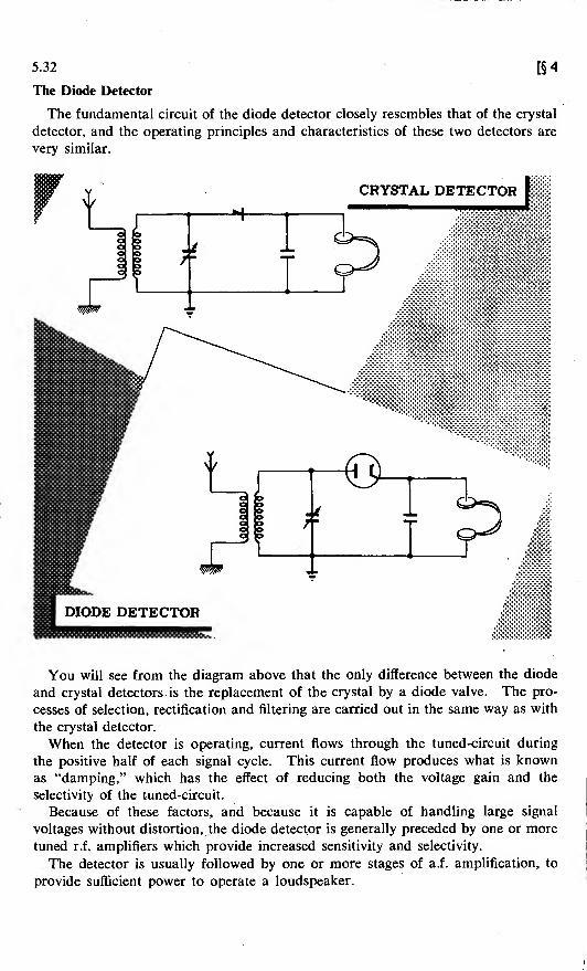
The Diode Detector
[§4
The fundamental circuit of the diode detector closely resembles that of the crystal
detector, and the operating principles and characteristics of these two detectors are
very similar.
CRYSTAL DETECTOR
Joo
I y
T
i
>h|—.—
,
t -i
You will see from the diagram above that the only difference between the diode
and crystal detectors. is the replacement of the crystal by a diode valve. The pro-
cesses of selection, rectification and filtering are carried out in the same way as with
the crystal detector.
When the detector is operating, current flows through the tuned-circuit during
the positive half of each signal cycle. This current flow produces what is knownas "damping," which has the effect of reducing both the voltage gain and the
selectivity of the tuned-circuit.
Because of these factors, and because it is capable of handling large signal
voltages without distortion, the diode detector is generally preceded by one or more
tuned r.f. amplifiers which provide increased sensitivity and selectivity.
The detector is usually followed by one or more stages of a.f . amplification, to
provide sufficient power to operate a loudspeaker.

§ 4] 5.33
The Grid-leak Detector
You have seen that since the diode detector cannot itself amplify, it is generally
used in a receiver which contains several separate stages of amplification. If,
however, you need a receiver in which the number of valves used has to be kept
low, you will have to use a more sensitive detector—one which amplifies as well
as detects.
In order to amplify, the detector must of necessity use a valve containing a control
grid, such as a triode, a tetrode or a pentode.
Of the triode detectors, the one which is easiest to understand is the grid-leak
detector. This is because the grid-leak detector is basically only a diode detector
followed by a stage of audio-frequency amplification.
Suppose that, to begin with, you examine the grid and cathode circuits of this
detector, and temporarily forget about the anode circuit. The result will be the
circuit shown below.
Note that this is basically the circuit of the diode detector. The control grid
of the triode is taking the place of the diode anode, the grid-leak resistor has
replaced the diode load or earphones, and the grid capacitor is acting as an r.f.
filter capacitor across the load.
When a modulated signal voltage is applied to this circuit, the grid will attract
electrons from the cathode during the positive half-cycles. The flow of current
through the grid-leak resistor to earth will produce a voltage drop across the grid-
leak resistor.
Because of the fact that current can flow in only one direction in the grid circuit,
this voltage will remain constant in polarity. The grid is thus biased, or kept at a
negative voltage with respect to the cathode.
The amount of bias will vary in accordance with the amplitude or the modulation
of the signal. In other words, the bias will vary at an audio-frequency rate.

[§45.34
The Grid-leak Detector (continued)
Now consider the complete grid-leak detector circuit.
Schematic ofagrid-leak detector
You will recall that the anode current of a triode is dependent on the grid voltage.
Consequently, the audio-frequency variations in bias should produce a correspond-
ing varying anode current.
Any radio-frequency component which there may be in the anode current is
filtered out by capacitors or by r.f. chokes placed in the anode circuit. As a result,
the voltage developed across the anode load is an amplified reproduction of the
audio-frequency voltage developed across the grid-leak resistor.
When there is no incoming signal, no bias is produced. Consequently, the anodecurrent is high when no signal is being detected. When a signal is received, the
grid becomes biased negatively, and the average amount of anode current decreases.
The amount of grief bias developed is equal numerically to the amount of grid
Current multiplied by the value of the resistance of the grid-leak. The larger the
grid-leak resistor, therefore, the greater will be the amplitude of the signal
developed.
For this reason, grid-leak detectors which were extremely sensitive would have to
use grid-leak resistors whose values were between one and five megohms.If, however, a strong signal comes in, it is quite possible that enough bias will
be created to cut off the flow of anode current during part of the cycle, thus pro-
ducing distortion.
In practice, therefore, the value of the grid-leak resistor has to be chosen so as
to be a compromise between the requirements of sensitivity and of minimumdistortion.

§ 4] 5.35
The Anode-bend Detector
The anode-bend detector employs a triode or pentode biased at, or near, cut-off.
The bias is usually provided by means of a cathode bias resistor; or, less frequently,
by means of a bias battery placed between grid and cathode. The anode current
will be at, or near, zero when no signal is being received.
*AnodeCurrent
Grid VoltageAverage value of anode current
^Signal value
applied to grid-cathode circuit
Action in anode bend detector|
When a modulated r.f. signal is impressed on the grid, there will be a pulse of
anode current during the positive half-cycle, and little or no anode current during
the negative half-cycle. The anode current will contain an amplified and rectified
version of the input signal.
The filtering of the r.f. component is accomplished by connecting a small capa-
citor between the anode and earth, and an r.f. choke in series with the anode load.
It is important that a small capacitor be used, since a capacitor which is too large
will tend to filter out the higher audio frequencies as well as the radio frequencies.

5.36 [§4
The Anode-bend Detector {continued)
In contrast to the action of the grid-leak detector, anode current in the anode-bend detector is at a minimum with no incoming signal.
Up to a certain point thereafter, the average anode current increases in direct
proportion to the amplitude or strength of the signal impressed on the grid.
Another important characteristic is that if care be taken not to drive the grid
positive, the anode-bend detector will consume no input power, and there will beno damping effect on the tuned-circuit. Consequently, the selectivity and fidelity
of the anode-bend detector is better than is that of the grid-leak detector.
On the other hand, one of the disadvantages of the anode-bend detector is thefact that its sensitivity to weak signals is much less than is that of the grid-leak
detector.
It also produces more distortion than does the diode detector; and it cannotdirectly provide a voltage to be used for automatic gain control. A typical anode-bend detector circuit is illustrated below.
Components Functions
R.F. coil and variable capacitor Provide selectivity, and couple detector topreceding r.f. amplifier stage
22-K resistor Provides cathode bias
0-5-(xF capacitor Bypasses signal round cathode bias resistor
001-jjt.F capacitor and r.f. choke Filter r.f. component of signal
270-K resistor Acts as anode load of detector
0-01-[aF capacitor Couples detector to following a.f. amplifierstage

§4]
REVIEW-
5.37
-Detectors
You have now learnt the basic principles of operation of four important types of
detectors. Let us review the basic circuits and operating characteristics of each type.
CIRCUITS
CRYSTAL DETECTOR
CHARACTERISTICSModerate sensitivity
Poor selectivity
Good fidelity
Capable of handling strong signals
Simple and economical to operate
High reliability (with modern
crystals)
s&T ..
O
DIODE DETECTORrWWA *-HT+
Low sensitivity
Poor selectivity
Good fidelity
High reliability
Capable of handling strong signals
Capable of supplying AGC voltage
GRID-LEAK DETECTOR
High sensitivity
Poor selectivity
Low fidelity
Moderate reliability
Easily overloaded by strong signals
Anode current decreases when a
signal is received
ANODE DETECTOR
Insensitive to weak signals
Good selectivity
Fair fidelity
Moderate reliability
Anode current increases when a
signal is received
ANODE-BEND DETECTOR
538 §5: TRF RECEIVERS-AUDIO AMPLIFIER
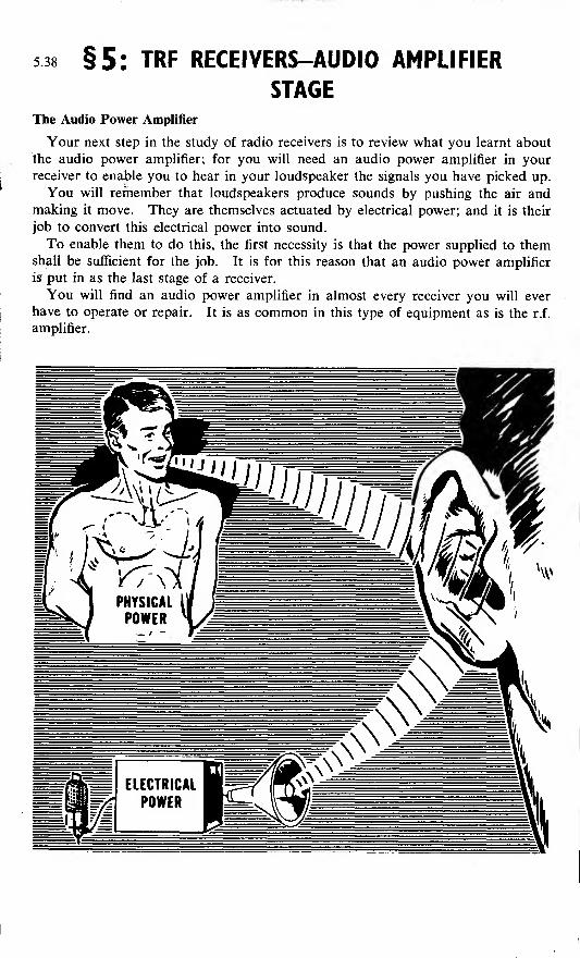
STAGEThe Audio Power Amplifier
Your next step in the study of radio receivers is to review what you learnt about
the audio power amplifier; for you will need an audio power amplifier in your
receiver to enable you to hear in your loudspeaker the signals you have picked up.
You will remember that loudspeakers produce sounds by pushing the air andmaking it move. They are themselves actuated by electrical power; and it is their
job to convert this electrical power into sound.
To enable them to do this, the first necessity is that the power supplied to themshall be sufficient for the job. It is for this reason that an audio power amplifier
is put in as the last stage of a receiver.
You will find an audio power amplifier in almost every receiver you will ever
have to operate or repair. It is as common in this type of equipment as is the r.f
.
amplifier.

§5] 5.39
A.F. Amplifier Tone Control Circuits
Now, unless something is done to correct the matter, it will frequently happen
that the sound emitted by a radio receiver will differ considerably from the original
sound applied to the transmitter.
The main reasons are that audio amplifiers do not amplify all frequencies by the
same amount, and that loudspeakers do not respond equally well tofall frequencies.
Other causes of distortion to the signal in transit are static and valve noise, both
of which are generally reproduced as high audio frequencies of a random nature.
Now, the tone or pitch of any sound depends on whether it contains a greater
proportion of high-frequency or of low-frequency waves. A high-pitched sound
has more high-frequency sound-waves; while a low-pitched sound consists mainly
of low-frequency sound-waves.
In order, therefore, to reduce the annoyance of interference by static and noise,
and to provide the deeper bass effect which most radio listeners prefer, many radio
receivers employ some means of tone control.
They accomplish this by eliminating from the signal some of the higher fre-
quencies which it contains—either shunting them to earth or bypassing them round
the output transformer.
The capacitor in the anode circuit shown above has a value such that it offers
a relatively easy path for the higher audio-frequencies; while the lower audio-
frequencies encounter a path of less opposition by travelling through the primary
coil of the transformer. In this way, the amount of high-frequency sound reaching
the loudspeaker is considerably reduced.
The variable resistor acts as a means of tone control. If the resistance is madevery high, the path through the capacitor to earth becomes one which offers high
opposition to the passage of high-frequency as well as to low-frequency signals.
Less high-frequency current will therefore flow through the bypass capacitor, and
there will be a rise in the pitch of the sound coming from the loudspeaker.

5.40 [§5
A.F. Amplifier Volume Control
You have already learnt one method of controlling the volume of a receiver.
This method involved varying the bias of the r.f. amplifier stage.
Now you will discover another commonly-used method of volume control, whichinvolves instead the detector and a.f. amplifier stages.
AFv., AMPLIFIER
DiodeDetector
ToLoudspeaker
7S»*
DETECTOR-OUTPUT VOLUME CONTROL
Notice that the detector in the circuit above is coupled to the a.f. amplifier by
means of an RC coupling circuit. The volume control is basically a voltage divider,
the moving arm tapping off the desired amount of signal voltage, which is then
applied—through the coupling capacitor—to the grid of the a.f. amplifier.
This type of volume control is also frequently employed in superhet receivers.
Some receivers employ a dual type of volume control. This type of control
regulates the gain in the first and second r.f. amplifier stages by varying the cathode
bias; and further controls the gain by varying the amplitude of the input signal
applied to the first a.f. amplifier.
GRID CONTROL OF RECEIVER

§5] 5.41
Comparison of R.F. and A.F. Amplifiers
Since most radio receivers you will encounter contain both r.f. and a.f . amplifiers,
you must possess a clear understanding of the differences between them, and of
the advantages and disadvantages of each.
Look carefully at the comparative table set out below.
R.F. Amplifiers
1. Designed to amplify frequencies
above 20,000 cycles.
2. Usually have tuned-circuits, thereby
adding selectivity.
3. Usually coupled to other stages by
r.f. transformers.
4. Precede the detector stage.
5. Designed for voltage amplification.
6. Triodes are rarely used, since they
lack stability and have to be neutral-
ised.
7. Generally employ variable-mu pen-
todes.
A.F. Amplifiers
1. Designed to amplify frequencies of
between 15 cycles and 20,000 cycles.
2. Untuned, and so do not add to selec-
tivity of set.
3. Coupled to other stages by a.f. iron-
core transformers, or by resistance-
capacitance coupling.
4. Follow the detector stage.
5. Usually designed for power ampli-
fication.
6. Very stable and not likely to oscillate.
If triodes are used, no neutralization
is required.
7. Generally employ triodes, beam-power tetrodes, or power pentodes.
5.42
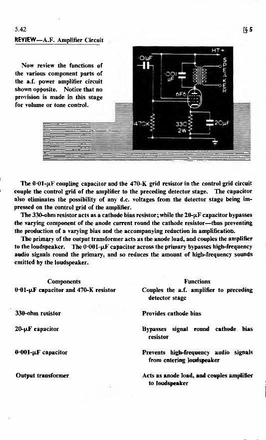
REVIEW—A.F. Amplifier Circuit
Now review the functions of
the various component parts of
the a.f. power amplifier circuit
shown opposite. Notice that no
provision is made in this stage
for volume or tone control.
[§5
The 0-01-fxF coupling capacitor and the 470-K grid resistor in the control grid circuit
couple the control grid of the amplifier to the preceding detector stage. The capacitor
also eliminates the possibility of any d.c. voltages from the detector stage being im-
pressed on the control grid of the amplifier.
The 330-ohm resistor acts as a cathode bias resistor ; while the 20-jaF capacitor bypasses
the varying component of the anode current round the cathode resistor—thus preventing
the production of a varying bias and the accompanying reduction in amplification.
The primary of the output transformer acts as the anode load, and couples the amplifier
to the loudspeaker. The 0*001-jaF capacitor across the primary bypasses high-frequency
audio signals round the primary, and so reduces the amount of high-frequency sounds
emitted by the loudspeaker.
Components
0*01-(iF capacitor and 470-K resistor
330-ohm resistor
20-fi.F capacitor
0*001-|aF capacitor
Output transformer
Functions
Couples the a.f. amplifier to preceding
detector stage
Provides cathode bias
Bypasses signal round cathode bias
resistor
Prevents high-frequency audio signals
from entering loudspeaker
Acts as anode load, and couples amplifier
to loudspeaker

§6: THE SUPERHETERODYNE RECEIVER 5.43
Introduction
The superheterodyne receiver is the most popular type of receiver in use today.
Practically all commercial home radios are of this type.
You will find a superheterodyne circuit in practically every piece of electronic
equipment which contains a receiver. This includes radar, echo-sounding and
communications equipment—any device, in short, which picks up and receives a
signal.
Your knowledge of the TRF receiver gives you a good start towards learning the
superheterodyne, because it uses all the basic components of a TRF—with three
additional units.
The block diagram of a superheterodyne below shows the three additional units
—a mixer, a local oscillator, and an intermediate frequency (i.f.) amplifier.
YV
fit)AA -
RFAmplifier
Detector AFAmplifier
THE TRF RECEIVER
RFAmplifier
LocalOscillator
IF Detector AFAmplifier Amplifier
THE SUPERHET RECEIVER

5.44 [§6
The Superhet at High Frequencies
At high frequencies, the TRF receiver does not work as well as it does at lower
radio frequencies. Above 20 Mc/s, the TRF circuit does not have the necessary
sensitivity and selectivity.
The superheterodyne receiver avoids the difficulties encountered with the TRFat high frequencies by converting the selected signal frequency to a lower (inter-
mediate) frequency (i.f.) which can be amplified more easily.
/HQSPIT-OAH OIT. **H
T(/fto-
GOOD• SENSITIVITY• SELECTIVITY• STABILITY
SUPERHETRECEIVER
TENDAYSLEAVEFORAll

§6] 5.45
How the Superhet Works
If you know why the superheterodyne was developed, you will easily learn
how it works.
TRF receivers use r.f. amplifiers with variable tuned-circuits to select and amplify
the received signal. If the receiver has three r.f. stages before the detector, it will
contain four tuned-circuits. You know that, if the best selectivity and sensitivity
are to be obtained, each of these four tuned-circuits must be tuned to the samefrequency.
But it is extremely difficult to make a multi-ganged tuning capacitor each section
of which will tune its circuit to exactly the same frequency as will the other
sections. Therefore, the gain and the selectivity of the TRF receiver are both
limited; for more r.f. stages cannot conveniently be added.
The superheterodyne receiver overcomes this problem by taking the incoming
signal and converting the carrier frequency to another frequency. This new fre-
quency is called the "intermediate frequency" (i.f.); and it is constant regardless
of the frequency to which the receiver is tuned.
The i.f. signal is amplified in a series of high-gain amplifiers which are pre-
tuned to this fixed i.f. frequency. Because it eliminates the many-ganged tuning
capacitor, the superhet with its fixed frequency i.f. amplifiers can be used to give
very large gains and very fine selectivity.
Here is how the signal frequency is changed in the superhet. The incoming
signal and the output of the local oscillator are fed into the mixer valve. Theanode current varies with both of these signals, which are of different frequencies.
A beat (or difference) frequency appears in the resulting signal.
This signal is then passed through the i.f. amplifiers, which are tuned to this
difference frequency.
The i.f. signal has exactly the same modulation as the r.f. carrier. The only
change has been the substitution of the i.f. frequency for the r.f.
THE SUPERHET RECEIVERS MAKE USE

5.46 [§ 6
Selectivity of the Superhet
When you tune a superheterodyne receiver to a station of 880 kc/s, you are
setting the tuned r.f. circuit to 880 kc/s, and at the same time you are automatically
tuning the local oscillator to 1345 kc/s.
Two signals—one of 880 kc/s, the other of 1345 kc/s—are thus fed into the
mixer stage. The output of this mixer stage contains a frequency of 465 kc/s,
which is the difference between the values of its two inputs.
If at the same time the aerial picks up another (unwanted) station at a frequency
of 1100 kc/s, the signal (if it were strong enough to get by the first tuned-circuit)
would be mixed with the local oscillator output in the mixer stage. This undesired
signal of 1100 kc/s would there produce a beat-frequency of 1345 minus 1100,
equals 245 kc/s.
The i.f. amplifier tuning is fixed at 465 kc/s, and only the "beat" signal at this
frequency will be amplified—i.e. only the required (880 kc/s) station will be heard.
Thus the superhet has selected the proper input signal on the basis of the frequency
of the beat signal produced in the mixer stage.
THE yaM4ped
KEEPS THE LOCAL OSCILLATOR
"TRACKING" THE TUNED RF
If you wanted to hear the 1100-kc/s station, the receiver would have to be re-
tuned. Turning the knob changes the frequency to which the r.f. amplifier is tuned,
and at the same time changes the local oscillator frequency. A two-section ganged
tuning capacitor is used for the purpose.
Tuning the receiver does not affect the i.f. stages. When the r.f. tuned-circuit is
set at 1100 kc/s, the oscillator will be generating a signal of 1565 kc/s. The i.f.
amplifier remains tuned to 465 kc/s.
Now it is the 1100-kc/s signal which produces the 465-kc/s beat-frequency. Thebeat produced by the 880-kc/s signal is the difference between its frequency and the
1565-kc/s local oscillator frequency—namely, 685 kc/s—and this frequency will
not be amplified by the i.f. stages.
For the superhet to work properly, the local oscillator must be adjusted so that
it will always tune to a frequency which is a fixed number of kilocycles different
from the desired r.f. frequency. Thus, as the receiver—that is, the r.f. tuned-
circuit—is tuned from 550 to 1600 kc/s, the local oscillator should tune from1015 to 2065 kc/s. Then any signal picked up at the frequency to which the
receiver is tuned will produce an i.f. frequency of 465 kc/s.
The designer's choice of i.f. depends on the nature of the equipment. In most
domestic radio receivers intended for medium- and long-waveband reception, the
i.f. lies between 450 and 480 kc/s.

§ 6] 5.47
R.F. Amplifier Stage
It is not essential for a superhet receiver to contain an r.f. amplifier stage. The
signal from the aerial would then be fed through an r.f. transformer to the signal
grid of the mixer or converter stage.
But you will encounter many receivers which do contain stages of r.f. amplifica-
tion preceding the mixer; so you will have a better understanding of the operation
of superhet receivers if you know the reasons which count in favour of including
an r.f. amplifier stage.
The primary reason for having an r.f. amplifier is to improve the signal-to-noise
ratio. The mixer stage usually produces more valve noise than does an r.f. stage
of amplification. The signal, plus this valve noise, is then amplified by the follow-
ing i.f. amplifier stage.
But if the signal strength is increased by placing an r.f. amplifier stage before the
mixer,, less amplification is required in the i.f. amplifier stage. And since valve
noise produced by the mixer is not amplified as much as it was when no r.f. stage
was present, a better signal-to-noise ratio is obtained.
A further advantage of having an r.f. amplifier stage is related to radiation from
the oscillator stage.
Do not forget that this oscillator is really a low-powered transmitter. If there
is no r.f. amplifier stage, the oscillator is connected through the mixer stage to the
aerial, which will radiate some energy from the oscillator.
This radiated signal may cause interference with reception in nearby receivers;
it may also divulge the location of the receiver.
This radiation may be reduced or prevented by using one or more stages of
r.f. amplification, and by carefully screening the oscillator stage.
RADIATION FROM A SUPERHETRECEIVER MAY REVEAL THELOCATION OF A SHIP

5.48 [§ 6
R.F. Amplifier Stage (continued)
The third advantage of having an r.f. amplifier stage is concerned with selectivity.
You will recall that in the TRF receiver the r.f. amplifier stages enabled the
operator to select the desired signal from a group of signals whose frequencies
were very close to one another. The r.f. amplifier in a superhet, on the other hand,
serves to prevent interference from a signal whose frequency may be several hundred
kilocycles above that of the desired signal.
This type of interference is called "image-frequency," or "second-channel," inter-
ference.
Let us assume that you have a superhet receiver without an r.f. amplifier stage,
and that the receiver is tuned to a station operating at a frequency of 600 kc/s.
The oscillator in the receiver will be tuned to 1065 kc/s, and the resulting i.f. signal
will have a frequency of 1065 kc/s minus 600 kc/s, or 465 kc/s.
If, however, there is a powerful station nearby broadcasting at a frequency of
1530 kc/s, some of the signal from this station will enter the mixer stage, where
it will beat against the signal from the oscillator. The resulting signal will be
1530 kc/s minus 1065 kc/s, or 465 kc/s—the same intermediate frequency as that
produced by the desired station.
The i.f. amplifier stage will amplify both signals equally well, since they are
both at the correct frequency of 465 kc/s.
This type of interference produces whistles, and a confusing mixture of sounds
coming out of the loudspeaker.
So, when the intermediate frequency is 465 kc/s, second-channel interference is
produced when there is a second station broadcasting at a frequency twice the
intermediate frequency, or 930 kc/s, above that of the desired signal.
, Second-channel interference can be reduced by the use of an r.f. amplifier stage
feefore the mixer.
In any receiver in which second-channel interference might present a problem,
however, one tuned-circuit is not enough to guarantee the elimination of this inter-
ference. There may be as many as two or three stages of r.f. amplification at the
signal frequency before the signal is fed into the mixer.
These stages are not made as selective as are those in a TRF receiver; but they are
selective enough to discriminate between the desired signal and the image frequency.
These stages do not present the alignment problems of the TRF, since none of
them needs to be sharply tuned to the signal frequency.

§6]5.49
The Local Oscillator
In a superhet receiver circuit, the local oscillator is tuned by a variable capacitor
ganged to those of the tuned r.f . circuits.
It is tuned to oscillate at a frequency which differs from that to which the r.f.
circuits are tuned by a fixed amount for every position of the tuning dial.
The local oscillator output is mixed with the r.f. carrier. The fixed frequency
difference (the i.f.) is part of the output of the mixer.
AFAmplifier
LocalOscillator
The process of mixing or beating two frequencies together to get a different
frequency is called "heterodyning."
The result of this mixing is a frequency which is above the audio-range—in other
words, a supersonic frequency. That is why the receiver was originally known as
the "supersonic heterodyne."
The particular superhet you will study will have a tuned-grid type oscillator
operating at 465 kc/s above the r.f. frequency. The i.f. is therefore 465 kc/s. The
variable capacitor in the oscillator tuned-circuit is ganged with the tuning capacitor
in the aerial tuned-circuit, as shown in the illustration on page 5.61.
As the receiver is tuned to an incoming signal, the local oscillator is also varied
to keep it at a frequency of 465 kc/s higher than the signal to which the aerial
circuit is tuned. The table below gives examples of typical operating frequencies.
SOME TYPICAL OPERATING FREQUENCIES FOR THE SUPERHET
Frequency to Frequency I.F.
which R.F. Circuits of Difference
are tuned Local Oscillator Frequency
in kc/s in kc/s in kc/s
550 1015 465
710 1175 465
880 1345 465
1440 1905 465

5.50 [§ 6
The Local Oscillator (continued)
There are several types of oscillators which can be employed as local oscillators.
But the types most frequently used are modifications of the Armstrong and of the
Hartley oscillators.
An ideal local oscillator should possess the following characteristics:
1. The frequency of its output should be stable, and free from drift at all settings.
2. It should be capable of delivering sufficient voltage to the mixer.
3. The amplitude of the output should be constant over the entire frequency range.
4. The oscillator should have minimum inter-action with other tuned-circuits. (If
the oscillator inter-acts with other tuned-circuits, there will be a change in
oscillator frequency every time the other circuits are tuned.)
5. The oscillator should radiate a minimum of energy into space.
The oscillators found in re-
ceivers used for medium broad-
cast band reception are usually
designed to produce a signal
whose frequency is higher than
the frequency of the incoming
radio wave.
The tuning capacitor of the
oscillator is ganged with the
capacitor of the r.f. tuned-
circuit so as to maintain a con-
stant difference in frequency as
the receiver is tuned across the
band. This is known as "track-
ing." A condition of perfect
tracking occurs when the oscil-
lator tuned-circuit is resonant
exactly the right number of kc/s
(i.f.) higher than the r.f. tuned-
circuits, for all settings of the
tuning dial.
The process of adjusting the
tuned-circuits so as to maintain
this constant difference at both degrees rotation of ganged capacitor
the high and low ends of the tuning bands is known as "aligning."
The process of adjusting a receiver to obtain good tracking will be dealt with
more completely in the Section later on in this Part dealing with the alignment and
adjustment of superhet receivers.

§6] 5.51
The Local Oscillator (continued)
There are two ways of designing the oscillator tuned-circuit so that it will produce
a signal the right number of kc/s higher than that of the r.f. circuit.
One method employs a special kind of ganged capacitor. The plates of the
oscillator section of this capacitor are made smaller than the plates of the r.f.
section. Since the capacitance of the oscillator section is less than that of the
r.f. section, the oscillator section will resonate at a higher frequency.
In addition, the plates of the oscillator section are so shaped as to produce correct
tracking as the plates are meshed or unmeshed.
© Ganged capacitors with
sections of differing sizes (DGanged capacitors with
identical sections
When both sections of the capacitor are identical, the total capacitance of the
oscillator tuned-circuit is reduced by placing a capacitor, called a "padder" capaci-
tor, in series with the oscillator tuning capacitor. This padder is often an adjust-
able mica capacitor. As a result of this reduction in capacitance, the oscillator
circuit resonates at a higher frequency. The capacitance of the padder is usually
between 500 and 1000 pF. In the process of alignment, the padder capacitor is
adjusted for best tracking at the low-frequency end of the band.
In order to align the superhet receiver at the high-frequency end of the band,
trimmers are placed in parallel with each section of the tuning capacitor, just as
they are in TRF receivers. These trimmers will usually have a capacitance varying
between 2 and 20 pF.
The end vanes of each section of the ganged capacitor are usually split to provide
tracking adjustment at intermediate points.
TYPICAL RFCIRCUIT
TYPICAL OSCILLATORCIRCUIT

5.52 [§ 6
How the Mixer Stage Works
The mixer works on the following principle. If two different frequencies are
mixed or combined in a valve, the output will contain many different frequencies,
of which the four principal ones are:
1. The modulated r.f. signal from the r.f. amplifier or the aerial.
2. The unmodulated local oscillator r.f. output.
3. The sum of 1 and 2.
4. The difference between 1 and 2.
The difference frequency is the desired i.f. signal.
The signals resulting from the mixing of a modulated carrier with the unmodulatedoutput from the oscillator will have exactly the same modulation shape as the
original carrier wave. The tuned-circuits of the i.f. amplifier are used to select the
desired signal, and to discriminate against the others.
V.+® Modulated RF Signal Input
Local Oscillator Output
Mixed Signal
V.-
® Modulated IF Signal (Desired Output From Mixer)

§6] 5.53
How the Mixer Stage Works (continued)
Of the several frequencies present in the anode circuit of the mixer valve—the
original signal, the oscillator signal, a signal whose frequency is the sum of the
first two signals, and another signal whose frequency is equal to their difference
—
only the latter, or i.f., signal must be passed on to the next stage.
This is accomplished by using the primary of a tuned i.f. transformer as the
anode load. The primary and secondary coils are tuned to the intermediate
frequency which, in the receiver you will consider in this Part, is 465 kc/s. In
this manner, maximum response is obtained for the i.f. signal.
This i.f. signal is passed on to the following i.f. amplifier stage, while the other
signals are rejected by the selective action of the tuned i.f. transformer.
HOW THEMIXER STAGE
WORKS . . -
1000 Kc/s
ToDetector
Oscillator OSCILLATOR SIGNAL1465 Kc/s

5.54 [§ 6
Mixer Valves and Frequency Changers
The three types of mixer circuit you will meet most frequently are illustrated
below.
The first employs a pentode as the mixer valve, and in the circuit illustrated the
r.f. signal is injected at the control grid and the oscillator signal at the suppressor
grid. The oscillator signal could equally be coupled inductively or capacitively
to the cathode, to the control grid, or to the screen grid of the mixer.
HEPTODEMIXERIsUPPRESSOR
(be
- OSCILLATOR *The second type of mixer circuit employs a heptode—a valve
with seven electrodes. Heptodes are of two kinds, one of whichis designed simply as a mixer valve; the other type combines
the functions of mixer valve and oscillator valve. Valves of
this latter kind are known as "frequency-changers."
In the heptode mixer, the r.f. and oscillator signals are injected
at grids G-l and G-3. In the heptode frequency-changer, the
cathode, G-l and G-2 act as a triode in an oscillator circuit, and
the r.f. signal is fed to the "injector grid" G-3.
-HT+ ..rf
- -^GRID
\&iiE-3
m¥OSCILLATOR
The third and most common type is a triode-hexode fre-
quency-changer valve circuit. The triode-hexode consists of a
triode and a hexode (six-electrode valve) enclosed in one en-
velope and sharing a common cathode. The triode portion is
used as the valve in the oscillator circuit, and the r.f. signal is
applied to G-l.
-HT+
RFAMP
I
Trl-Al"!
IFAMPZ=!~
TRIODE HEXODEHEXOOE ANOOE SCSEEN
s+ s. GRIDS
2HPSIGNALGRID E:
zk
OSCILLATORSECTION

§ 6] 5.55
The I.F. Transformer
I.F. transformers may be tuned to the correct frequency by adjusting small mica
trimmer capacitors. This process of adjustment will be described later.
The coils and capacitors are mounted in small metal cans which act as screens.
Small holes in the tops of the cans make it possible to vary the value of the capaci-
tors by turning adjusting screws without removing the screening-can.
AdjustingScrews
TrimmerCapacitor
SecondaryCoil
Primary Coil
Primary Leads
Secondary Leads
Many i.f. transformers have powdered iron-dust cores and fixed mica capacitors.
Tuning is accomplished by turning a set screw which moves the dust core in or
out of the coil. This type of transformer is known as a "permeability-tuned"
transformer.
No matter what method is used to tune the transformer, you will find that nearly
all ii. transformers are double-tuned. This means that both primary and secondary
are tuned to the intermediate frequency. This produces a very high degree of
selectivity. -

5.56 [§6
The I.F. Amplifier
The intermediate-frequency amplifier is permanently tuned to the theoretically
constant difference in frequency between the incoming r.f. signal and the local
oscillator.
The tuning of an i.f. amplifier stage is accomplished by means of two tuned i.f.
transformers. The one associated with the grid circuit of the amplifier is called
the "input" i.f. transformer, while the one associated with the anode circuit is called
the "output" i.f. transformer.
The valves employed in i.f. amplifiers are normally variable-mu pentodes.
Since this amplifier is designed to operate at only one fixed frequency, the i.f.
circuits may be adjusted for high selectivity and maximum amplification. It is in
the i.f. stage that practically all the selectivity and voltage amplification of the
superhet is developed.
Simple superhet receivers may contain only one i.f. amplifier, while more com-plex receivers contain as many as three i.f. amplifier stages.
The choice of intermediate frequency is a compromise between the desire for
high selectivity and the need to reduce the possibility of second-channel inter-
ference. Use of a low intermediate frequency, such as 175 kc/s, results in high
selectivity, but increases the possibility of second-channel interference. A high
intermediate frequency reduces the possibility of second-channel interference, but
reduces the selectivity.
The choice of 465 kc/s as the intermediate frequency for the receiver described
in this book represents a compromise between these two undesirable extremes.
-HT+
IF Output
Detector
IF Input

§6] 5.57
The Detector and First Audio Stage
The conversion of the i.f. signal into an audio signal is accomplished by means
of a diode or crystal detector.
The detector circuit in the superhet receiver will sometimes be combined in one
valve with the first stage of audio amplification. The receiver's manual volume
control and automatic gain control are also often included in this part of the circuit.
The valve employed for this purpose may be a double-diode triode. The diode
section acts as the detector, and the triode section as the audio amplifier.
Since a detailed explanation of the operation of diode detectors has already been
given, the operation of the diode detector which is shown in the accompanying
circuit diagram will be only briefly described.
HT+
The diode acts as a rectifier, and conducts current during that half of the signal
cycle in which the anode is made positive with respect to the cathode. During
the other half-cycle, when the anode is negative, no current flows.
This produces a pulsating d.c. which contains two components, one of which is
audio frequency and the other intermediate frequency. The filter circuit, consist-
ing of the 47-K resistor and the two 200-pF capacitors, filters out the i.f. component.
The audio component of the pulsating d.c. produces an a.f. voltage across the 47-Kfixed resistor and the 500-K potentiometer.
The a.f. voltage is applied to the grid of the first audio amplifier, and amplified
at the anode as shown. RL and C2 are part of the Automatic Gain Control (AGC)circuit which you will study later.
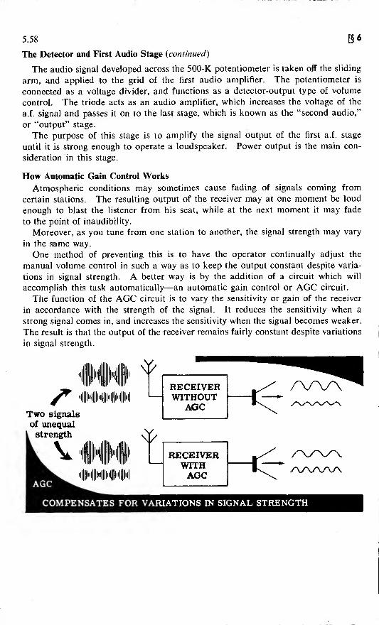
5.58 [§6
The Detector and First Audio Stage (continued)
The audio signal developed across the 500-K potentiometer is taken off the sliding
arm, and applied to the grid of the first audio amplifier. The potentiometer is
connected as a voltage divider, and functions as a detector-output type of volume
control. The triode acts as an audio amplifier, which increases the voltage of the
a.f. signal and passes it on to the last stage, which is known as the "second audio,"
or "output" stage.
The purpose of this stage is to amplify the signal output of the first a.f. stage
until it is strong enough to operate a loudspeaker. Power output is the main con-
sideration in this stage.
How Automatic Gain Control Works
Atmospheric conditions may sometimes cause fading of signals coming from
certain stations. The resulting output of the receiver may at one moment be loud
enough to blast the listener from his seat, while at the next moment it may fade
to the point of inaudibility.
Moreover, as you tune from one station to another, the signal strength may vary
in the same way.
One method of preventing this is to have the operator continually adjust the
manual volume control in such a way as to keep the output constant despite varia-
tions in signal strength. A better way is by the addition of a circuit which will
accomplish this task automatically—an automatic gain control or AGC circuit.
The function of the AGC circuit is to vary the sensitivity or gain of the receiver
in accordance with the strength of the signal. It reduces the sensitivity when a
strong signal comes in, and increases the sensitivity when the signal becomes weaker.
The result is that the output of the receiver remains fairly constant despite variations
in signal strength.
Two signals
of unequali strength
RECEIVERWITHOUT
AGC
'#'l|||l'i||IM||M|||.i
/\/\/\Ay\
COMPENSATES FOR VARIATIONS IN SIGNAL STRENGTH

§6] 5.59
How Automatic Gain Control Works {continued)
The AGC circuit most frequently encountered is incorporated in the diodedetector stage. It requires that at least one, and preferably all, of the precedingi.f
. amplifier, mixer, or r.f. amplifier stages employ the variable-mu type of valve.
It also requires some means of transferring the negative voltage which is de-veloped by the AGC circuit to the control grid of these variable-mu valves.
Ao*PlifU
In the diagram above, the resistor
R-l is the diode load, the i.f. filter
being omitted for clarity. When the
anode is positive with respect to the
cathode, current flows through R-l
from (a) to (b). Thus (a) becomes
negative with respect to (b).
The waveform appearing at the
negative end of R-l (a) is actually an
audio wave with a negative d.c. com-
ponent. The negative d.c. component varies with the signal strength.
The AGC filter circuit, consisting of R-2, C-2, filters out the audio, and C-2
charges up to the negative d.c. component. It is this negative voltage that is applied
through the AGC line to the grids of the variable-mu valves in the preceding stages.
The amount of negative voltage developed at (a) will vary with two factors. One
is the relatively rapid variation in strength and amplitude produced by the audio
signal at the transmitter during the process of modulating the carrier wave. The
second is the slower variation in negative AGC voltage produced by variations in
signal strength due to atmospheric conditions.
If the rapid variations produced by the audio modulating signals were allowed
to travel down the AGC line to the preceding i.f. or r.f. stages, undesirable effects
would be produced. The AGC filter circuit, consisting of R-2 and C-2, is added
to remove these audio frequency variations of the negative AGC voltage.
The slower variations in signal strength which show up as a slowly-varying
negative d.c. voltage are not bypassed, but pass down the AGC line to the grids
of the preceding amplifier stages.

5.60 [§6
How Automatic Gain Control Works (continued)
Since these preceding i.f. and r.f. stages employ variable-mu valves, the amount
of gain produced in each stage is dependent on the amount of bias present on the
control grid.
When the signal increases in strength, a high negative AGC voltage is developed
between one end of R-l and earth. This negative voltage is applied through the
AGC filter circuit and the AGC line to the control grids of the preceding stages,
thus increasing the negative bias on these valves.
Because of this increased bias, there is a considerable decrease in the amount of
amplification or voltage gain. In other words, the sensitivity of the receiver has
been reduced.
On the other hand, when a weak signal enters the receiver, a much smaller
negative AGC voltage is developed. The bias on the amplifier valves is reduced,
resulting in considerably greater receiver sensitivity and voltage amplification for
the weak signal.
As far as the human ear is concerned, these variations in receiver sensitivity as
the signal strength varies occur almost instantaneously, thus producing an output
whose volume is reasonably constant.
IF AMPLIFIER, DETECTOR AND FIRST AUDIO AMPLIFIER
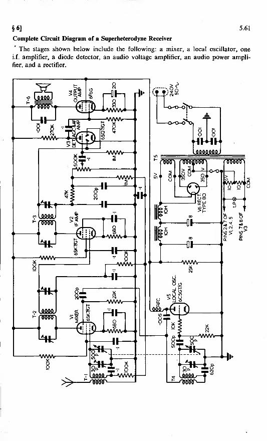
§6] 5.61
Complete Circuit Diagram of a Superheterodyne Receiver
* The stages shown below include the following: a mixer, a local oscillator, one
i.f. amplifier, a diode detector, an audio voltage amplifier, an audio power ampli-
fier, and a rectifier.
»

5.62 [§6
Receiving C.W. Signals
You may recall from your study of transmitters that there are several methods
of impressing intelligence upon a carrier wave. One of these methods is known as
"amplitude modulation." The superhet receiver we have considered up to this
point is designed for use with amplitude-modulated (AM) signals.
Another method of conveying intelligence involves the interruption of a carrier
wave in accordance with a code such as the Morse Code. These signals are called
"interrupted continuous wave" or "CW signals."
Since there is no modulation in this type of signal, it cannot be detected by crystal
or diode detector circuits. In order to hear the signal, it is necessary to use a
detector which employs the heterodyne principle.
The heterodyne principle involves mixing the CW signal with a signal obtained
from an oscillator. The result of this mixing is an AM signal which is interrupted
in the same manner as was the original CW signal.
This AM signal can then be detected, and the familiar "dit-dah" sound of code
will be heard in the earphones or loudspeaker.
NO SOUND DAH-DIT-DAH

§ 6] 5.63
The Heterodyne Principle
You may have observed that when two adjacent piano keys are struck at the
same time, a distinct throbbing sound can be heard. This throbbing sound, known
as a beat, has a frequency equal to the difference between the frequencies of the
two notes struck.
If the two notes struck have frequencies of 264 and 297 cycles respectively, the
beat frequency will be equal to the difference between them, or 33 cycles.
Similarly, when two alternating voltages of slightly different frequencies are com-
bined in a detector, the resultant voltage produced in the output will include a
frequency which is equal to the difference between the frequencies of the two original
voltages. This is the basis of the heterodyne principle.
For example, if two inaudible r.f. waves whose frequencies are 465 kc/s and
466 kc/s respectively are applied to a detector valve, the smaller wave (A) will
add and subtract from the larger wave (B) to make the amplitude of the larger
wave (B) vary in the manner shown below. The rate of variation of the amplitude
of wave B is the difference between the frequencies of the two waves—in this case
1 kc/s.
Observe that wave B, because of the introduction of wave A, has been trans-
formed into an amplitude-modulated wave. The audio modulation can be heard
by detection of this AM signal.
llllllliitiiiiiiiiiiiiiii______l____HKR!19K___wl
Wave A j\ A A A:\j\jv
+6 6KC/S
Wave Bf-f -f-4 -1— * t-
lKc s Difference Frequency
Wave B ' \/|Modulated i
J
/ ! 1 Volt
/ 1 Volt— -+- - *—
I A 1A ^ A iA A, r P\ * (\. )t\
\ U_U.j4.44-H -4-4-
!• i voit
s466 Kc/s

5.64 [§ 6
The Beat Frequency Oscillator
In superhet receivers the reception of CW signals is accomplished by means of a
separate oscillator called a "beat frequency oscillator" (BFO), capacitively coupled
to the diode detector or into the previous i.f. amplifier.
The BFO may be a Hartley oscillator tuned to a frequency 1 kc/s above or below
that of the intermediate frequency. Thus, if the i.f. is 465 kc/s, and the frequency
of the BFO is 466 kc/s, a 1-kc/s audio signal will be produced in the diode detector.
The frequency of the BFO is variable over a small range, making it possible to vary
the pitch of the resulting beat note until a satisfactory tone is produced.
Coupling between the BFO and the detector or i.f. amplifier is sometimes achieved
through the stray capacitance of the wiring, and the coupling capacitor is then
omitted.
HT+

Analysis of the Local Oscillator Stage
5.65
THE
To mixer grid
200p1I
HT+
005
500p
ll-wvwiok \—y
SOOp
LocalOscillator
V5 6C5GT/G
22K
620pPadder
Now that you have seen the complete circuit of a superhet, it will be worth
your while to spend a little time analysing the functions of the circuit components
used in the oscillator, the mixer, and the detector stages.
The local oscillator circuit is basically that of an Armstrong oscillator. Feedback
is accomplished inductively, using coil T-4. The variable tuning capacitor is
ganged to the variable tuning capacitor of the mixer stage. The 620-pF capacitor
is a padder capacitor, used to make adjustments in the process of aligning the
oscillator tuned-circuit. It also serves to reduce the total capacity of the oscillator
tuned-circuit so that the oscillator resonates at a frequency higher than that of the
incoming signal.
The 500-pF capacitor is a grid capacitor used to couple the tuned-circuit to the
grid, while the 22-K resistor is the grid-leak resistor. The r.f. choke is the anode load
;
it also prevents r.f. from going towards the power supply. The 005-fj.F capacitor
couples the r.f. output of the anode circuit back to the coupling coil, while effectively
blocking the flow of direct current.
Finally, the 200-pF capacitor is used to couple the output of the oscillator to the
suppressor grid of the mixer. The 10-K resistor connected to the valve grid helps to
keep the oscillator frequency stable.
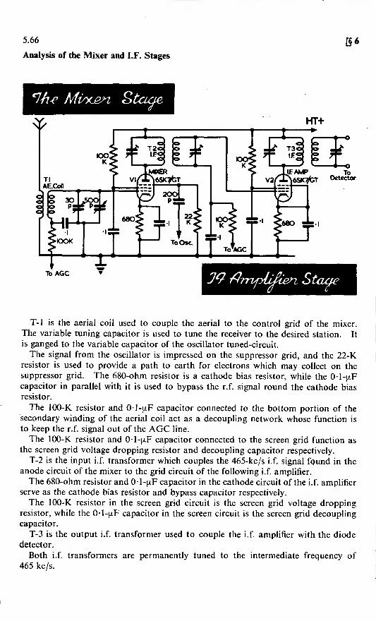
5.66
Analysis of the Mixer and I.F. Stages
[§6
*7/ie Mvxjgn Staae
To AGC 39 tfrnpLfden Stage
T-l is the aerial coil used to couple the aerial to the control grid of the mixer.
The variable tuning capacitor is used to tune the receiver to the desired station. It
is ganged to the variable capacitor of the oscillator tuned-circuit.
The signal from the oscillator is impressed on the suppressor grid, and the 22-Kresistor is used to provide a path to earth for electrons which may collect on the
suppressor grid. The 680-ohm resistor is a cathode bias resistor, while the 0-l-[xF
capacitor in parallel with it is used to bypass the r.f. signal round the cathode bias
resistor.
The 100-K resistor and 01-(xF capacitor connected to the bottom portion of the
secondary winding of the aerial coil act as a decoupling network whose function is
to keep the r.f. signal out of the AGC line.
The 100-K resistor and 01 -[xF capacitor connected to the screen grid function as
the screen grid voltage dropping resistor and decoupling capacitor respectively.
T-2 is the input i.f. transformer which couples the 465-kc/s i.f. signal found in the
anode circuit of the mixer to the grid circuit of the following i.f. amplifier.
The 680-ohm resistor and 0-1 -[xF capacitor in the cathode circuit of the i.f. amplifier
serve as the cathode bias resistor and bypass capacitor respectively.
The 100-K resistor in the screen grid circuit is the screen grid voltage droppingresistor, while the 1-[xF capacitor in the screen circuit is the screen grid decoupling
capacitor.
T-3 is the output i.f. transformer used to couple the i.f. amplifier with the diode
detector.
Both i.f. transformers are permanently tuned to the intermediate frequency of
465 kc/s.

§6]
Analysis of the Diode Detector and First Audio Stages
5.67
The two 200-pF capacitors function as the detector filter capacitors. Their purpose
is to bypass the i.f. component of the signal to earth round the 47-K and 500-K diode
load resistors.
The 47-K resistor is part of the filter network, while the 500-K potentiometer also
acts as a bleeder resistor across the filter. It controls the amount of detector output
delivered through the 01-jxF coupling capacitor to the grid of the first audio
amplifier, and thus serves as a volume control.
The 1-meg. resistor and 1 -[xF capacitor in the AGC line filter out the relatively
rapid variations in AGC voltage produced by the audio component of the signal.
They allow the slower variations in AGC voltage produced by variations in signal
strength to pass unimpeded down the AGC line.
The 1-meg. resistor connected to the control grid serves as a path to earth for any
electrons that may accumulate on the grid. The 270-K resistor acts as the anode
load of the first audio stage, while the 001-(xF capacitor in the anode circuit couples
the ouipui of the first audio amplifier to the grid of the audio power amplifier.
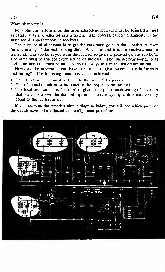
5.68 [§6
What Alignment Is
For optimum performance, the superheterodyne receiver must be adjusted almost
as carefully as a jeweller adjusts a watch. The process, called "alignment," is the
same for all superheterodyne receivers.
The purpose of alignment is to get the maximum gain in the superhet receiver
for any setting of the main tuning dial. When the dial is set to receive a station
transmitting at 980 kc/s, you want the receiver to give the greatest gain at 980 kc/s.
The same must be true for every setting on the dial. The tuned-circuits—r.f., local
oscillator, and i.f.—must be adjusted so as always to give the maximum output.
How does the superhet circuit have to be tuned to give the greatest gain for each
dial setting? The following aims must all be achieved:
1. The i.f. transformers must be tuned to the fixed i.f. frequency.
2. The r.f. tuned-circuit must be tuned to the frequency on the dial.
3. The local oscillator must be tuned to give an output at each setting of the maindial which is above the dial setting, or r.f. frequency, by a difference exactly
equal to the i.f. frequency.
If you examine the superhet circuit diagram below, you will see which parts of
the circuit have to be adjusted in the alignment procedure.

§ 6] 5.69
Sensitivity Measurements
Sensitivity measurements are used to determine how sensitive a receiver is. Areceiver may be operating normally as far as your ear can detect; but if the overall
gain of the set is low, you may not be able to receive some weak signals.
This failure would only show up by measuring the overall gain of your receiver,
and comparing the results with the specification laid down by the manufacturer.
If a receiver was tested and found to have low sensitivity, the cause would be
determined by checking the gain of each amplifier stage and comparing the results
with the specification, thereby determining which stage has the low sensitivity.
Consider a typical medium broadcast-band receiver. Broadcast receivers are
not designed to be very sensitive, since very powerful stations are relatively close to
the receivers. In these receivers, a loss of sensitivity would mean that you would
turn up the volume control and nothing more. Therefore, sensitivity measurements
are not necessary.
Only when reception becomes so poor that it is uncomfortable or impossible to
hear a station would you attempt to repair the receiver.

5.70 [§6
Sensitivity Measurements (continued)
In some receivers, sensitivity measurements are very important. In a radar
receiver, lack of sensitivity would mean that distant targets which should be detected
would not be noticed at all. Decreased gain in a communication receiver wouldmean that weak signals could not be heard.
If any of these devices have low sensitivity, you could not (unless you are a very
experienced operator) discover the fact merely by operating them, since you usually
have no way of obtaining all the necessary data. You cannot tell that a distant
target is present unless you pick it up; you cannot tell that a weak, distant trans-
mitter is calling you unless you hear the message.
The best check on the performance of the receiver is through sensitivity checks.
Here is a typical way sensitivity measurements would be made with receiving
equipment.
An output meter is used to measure the output of the last stage of the receiver.
The instruction book for the piece of equipment will tell how many micro-volts are
required as the input to this receiver for a standard output as measured on the
output meter. Using a signal generator which has a calibrated output, you inject
a signal of the proper frequency into the receiver input. You adjust the signal
generator output until you read the standard amount of output on the output meter.
By comparing the input you needed with the instruction book's data, you can tell
if the receiver is up to specification.
If the input you used is larger than that stated in the instruction book, yourreceiver has too low a sensitivity. You would then take stage-by-stage sensitivity
measurements to determine the weak stage.
Starting with the last stage of the receiver, you inject a signal of correct frequency,
and adjust the audio signal generator output until the standard receiver output is
obtained. If the input you used compares well with the instruction book data,
the last stage of the receiver is working properly.
You repeat this procedure for each stage, working backwards from the last stage.
That stage which requires a larger input than that specified in the instruction bookis the stage which has too low a gain.
DIRECTION OFSIGNAL INJECTION
(I&fH *f ifadU
TABLEA-F INPUTS
INPUT TO VOLTS
OUTPUT2ndAF
^ 1st AF
1.5
0.8
0.15
* 1,000 CYCLES OF^RDDOEj
ttZT INSTRUCTION BOOK^- DATA

§6] 5.71
Aligning the I.F. Section
If the gain of the i.f. amplifier is low, realignment may be necessary. The
procedure for this is as follows.
First stop the oscillator from oscillating by removing the valve, or by shorting
its grid to earth. This prevents any signal other than that of the signal generator
from entering the i.f. amplifier. You must also short the AGC line to earth, since
the AGC circuit, if operative, would tend to broaden the receiver response and thus
make it more difficult to align the receiver sharply.
The output meter leads are then connected across the speaker, and the signal
generator test leads are applied to the various test points in the i.f. section.
With the manual volume control at maximum, a modulated 465-kc/s signal is
injected into point 1, the grid of the i.f. amplifier. Using a trimming tool, adjust
the trimmers on the i.f. output transformer for a maximum output.
Next, inject the i.f. signal into point 2, the grid of the mixer stage, and adjust
the trimmers of the i.f. input transformer for a maximum output.
The trimmers on both the i.f. transformers are then again retrimmed slightly to
obtain optimum alignment of the i.f. section.
A further test which would also be carried out at this stage is the measurement
of the i.f. amplifier bandwidth.

5.72[§ 6
Aligning the Mixer and Oscillator
With the i.f. amplifier aligned, the r.f. tuned-circuits in the grid of the mixer andthe local oscillator are the next to be aligned.
Replace the oscillator valve (or remove the short from grid to earth), but leave
the AGC circuit shorted to earth. Then apply signal generator output betweenthe aerial terminal and earth (chassis); and set the signal generator to give a modu-lated r.f. output of 1500 kc/s.
The receiver dial is then set to 1500 kc/s, and a signal is observed on the outputmeter. With the trimming tool adjust the oscillator and r.f. trimmers to give maxi-mum output.
Now the r.f. circuit is tuned to resonate at 1500 kc/s, and the oscillator is tuned to
oscillate at 1965 kc/s.

§ 6] 5.73
Aligning the Mixer and Oscillator {continued)
The mixer and oscillator tuned-circuits must now be aligned at the low end
of the band.
Set the signal generator to 600 kc/s and the receiver dial to 600 kc/s. Thenadjust the oscillator padder capacitor to give maximum output. Now adjust the
oscillator to oscillate 465 kc/s above the incoming signal of 600 kc/s.
Although the dial is set at 600 kc/s, there is no assurance that the r.f. tuned-
circuit is tuned to 600 kc/s. The ideal alignment for maximum output is to have
the r.f. tuned-circuit exactly resonant at 600 kc/s, with the oscillator tuned to 465
kc/s above 600 kc/s.
First note the reading of the output meter, and then tune the receiver in one
direction slightly away from a receiver dial reading of 600 kc/s. Now readjust
the padder for maximum output. If the output reading is greater than it wasbefore, you have changed the setting of the tuning dial in the right direction. If the
output reading is less, you must tune the receiver in the opposite direction from the
600-kc/s dial reading.
Having found the right direction, continue to vary the setting of the tuning dial
and to adjust the padder until a maximum output is obtained. At this point the
r.f. circuit is tuned exactly to 600 kc/s, with the local oscillator tuned to 1065 kc/s.
Even so, however, the pointer on the tuning dial may not yet be opposite the
600-kc/s mark on the dial. It is necessary, therefore, to move the pointer relative
to the dial without moving the tuning capacitor spindle. The pointer is loosened
(e.g., unscrewed) and moved until it is opposite the 600 kc/s mark on the dial. It
is then re-tightened.
The final step in the alignment procedure is to re-check the alignment at the highend of the frequency band, and to re-adjust where necessary.

5.74
REVIEW—Superheterodyne Receiver
Superheterodyne. A type of re-
ceiver in which the r.f. signal is con-
verted to a lower frequency r.f., and
then amplified before detection. It
has much higher sensitivity, selectivity
and stability than has the TRF.
[§6
Mixer. This is the circuit in a
superhet which takes the r.f. signal
and beats it against the signal gene-
rated by a local oscillator. The resul-
tant constant-frequency signal is lower
in frequency than the r.f., and is thus
easier to amplify.
Local Oscillator. This circuit is
tuned simultaneously with the r.f.
tuned-circuits in such a way that its
output frequency is always a fixed
amount greater or less than the fre-
quency of the signal being received.
Its output is combined with the r.f.
signal in the mixer.
I.F. Amplifier. This is the section
of the superhet which selects and
amplifies one of the signals coming
from the mixer. Its input and output
are usually coupled by transformers of
which the primary and secondary are
both tuned. This results in high
selectivity.
Detector and A.F. Amplifier. These
circuits perform the same functions as
in the TRF receivers. In the superhet,
the diode detector is often combined
with the first a.f. amplifier stage.
30p" "JSOOp ^22K
Local
Oscillator
620p
IFInput
kz:200 200
S MIXER GRIDS AGC LI*

§«1
REVIEW—Superheterodyne Receiver (continued)
Automatic Gain Control (AGC).
This circuit compensates for variations
in signal strength. A diode rectifies
the signal, and the negative d.c. com-
ponent is applied to the r.f. and i.f.
amplifier grids. When the signal in-
creases, the diode output increases
—
thus putting more negative bias on the
r.f. and i.f. amplifiers and lowering
their gain.
Tracking. When the difference
between the local oscillator frequency
and the r.f. signal frequency is con-
stant over the entire tuning range of
the superhet, it is said to have perfect
tracking. This, however, is never
achieved in practice.
Beat Frequency Oscillator (BFO).
This is an oscillator used when it is
desired to receive CW signals with the
superhet. Its output is tuned close to
the frequency of the i.f., and is fed into
the detector or i.f. amplifier. It beats
with the incoming signal, producing a
beat note in the audio range. With a
BFO, a CW signal is heard as a pure
tone. Without a BFO, CW signals
are heard as a soft hiss, or not at all.
Amplifier
5.75
Diode Detector
AGC /± R-2 /t '
jC-2+_/
To first
AF amplifier
RF / Oscillator
Padder
O Trimmer
V ^#TRACKING : 465 Kc/s difference
over entire tuning range
I DFO
Signal
Second Channel Interference. If
the i.f. is 465 kc/s, then two signals
(one 465 kc/s above, and the other
465 kc/s below, the oscillator fre-
quency) will both send a signal through
the i.f. amplifier and to the loud-
speaker. One of them is the desired
signal; the other is an image. The
purpose of a tuned aerial coil and
tuned r.f. amplifiers is to eliminate this
second channel interference.
550KC/8

5.76 §7: FAULT-FINDING
Introduction
It is now time for you to tackle the problems of finding the various types of fault
which are likely to occur in electronic equipment.
Before you begin to practise fault-finding of any kind on actual equipments, how-
ever, there are two matters of the utmost importance to which you must give your
careful attention.
(i) You must learn to develop a logical approach to the whole problem of fault-
finding in general,
(ii) You must learn how to select and how to use various types of test instrument.
THINK ABOUTFAULTFINDING. . . .
A LOGICALPROCEDURE
LEADS TO AQUICK SOLUTION
Though you will learn how to set about the logical finding of faults on an actual
piece of equipment—the superhet—which you have already studied, remember that
the general priciples of fault-finding which you will learn can also be applied to
electronic equipments of any other kind. Fault-finding is merely problem-solving.
Learning how to use test instruments properly, however, is essentially a matter
of practice, and cannot be satisfactorily learnt from a book. Full instructions on
how to use any particular test instrument, however, are given in the appropriate
manufacturer's handbook.

5.77§7]
Fault-finding Procedure
Step I—Collate the SymptomsThe first step in fault-finding is to ascertain the symptoms of the fault.
Before you can do this, you must obviously be in a position to recognize thenormal state of the equipment. In the case of the superhet on which you will doyour fault-finding practice, for example, the equipment is considered to be in thenormal state when signals can be received over the whole of the tuning range, andwhen the volume of the output can be varied without causing noticeable distortion.Under service conditions, you will either be told the symptoms of a fault by the
operator of the equipment, or you will have to find them for yourself. In the lattercase you find out how the equipment differs from its normal state by operating it,
and by using built-in metering facilities where they exist.
In more complicated and larger equipments, extensive metering and monitoringfacilities are normally provided—for example, a switched meter or meters may bebuilt into a large transmitter which can be used to measure various currents in thecircuit. On radar equipments it is often possible to use one of the cathode raytubes of the set to display waveforms at different points in the circuit.
I"1
!Ih.'llll.
Step 2—Decide which Stage is Faulty
It may be possible at this point, from, your knowledge of the symptoms, todecide in which stage or group of stages the fault is likely to be.
Always, however, think carefully about the symptoms before you actually doanything to remedy them.

5.78 B 7
Fault-finding Procedure (continued)
Step 3—Inspect the Equipment
Many defects can be found at once by using your senses of sight, hearing, touch,
and smell. Once you have heard a transformer sizzle and smelt the smoke, you
will be able to spot a burned-out power transformer without even turning the chassis
over
!
Loose ,.. _ _„ _.vajve JUtSsT/5^?^ Discoloured
resistor
SSSi«« Leaking transformerconnection
Visual inspection does not take long. In about two minutes you should be able
to see the trouble, if it is the kind that can be seen at all.
Start your inspection with the equipment switched off, and look for:
(i) Loose Valves—A valve which is not properly seated in its socket may not be
making proper contact with the rest of the circuit. Push all valves firmly
into place,
(ii) Shorts—Any terminal or connection which lies close to the chassis or to another
terminal should be examined for the possibility of a short. Look for and
remove any stray blobs of solder, bits of wire, nuts or screws.
It sometimes helps to give the chassis a not-too-vigorous shake (if that be
possible), listening for any tell-tale rattle.
Remember to correct any condition which may cause a short circuit. If it isn't
causing trouble now, it will begin to do so in the future.
(iii) Loose, broken or corroded connections—These could quite easily be the source
of the trouble.
(iv) Damaged Components—Look for discoloration, melting insulations, leaks from
oil-filled transformers. Remember, however, that these components may have
been damaged by the fault, and may not necessarily be the cause of it.
The component may be protected by a fuse. Check whether the fuse has
blown—and if it hasn't, find out why it hasn't. A fuse with too high a rating
may have been fitted, or there may be a short across the fuse holder.
After inspecting the switched-off equipment and remedying all obvious defects,
switch on and continue your inspection.
After switching on the equipment, look for:
(i) Overheating parts—If any part smokes, or if you hear anything which sounds
like boiling or spluttering, switch off immediately. There is a short circuit
somewhere which you have missed in your first inspection.

§7] 5.79
Fault-finding Procedure (continued): Step 3—Inspect the Equipment (continued).
Use your ohmmeter, if necessary, to locate it, beginning in the neighbour-hood of the smoking part,
(ii) Cold Valves—In some valves it is possible to see the glow of the heater fila-
ment; with others it is necessary to wait until the filament has had time to
warm up, and then to touch the valve to see if it is warm.If there is no heater glow and the valve is cold, either the valve is unservice-
able or there is a break in the heater connections.
Remove suspect valves, and test for continuity across the heater pins. If theohmmeter reading is very high, or infinity—the valve is unserviceable.
If the ohmmeter indicates continuity through the heater, the fault lies in theheater supply circuit. Check that the valve is making proper connection withits socket, and then use an a.c. voltmeter to find the break in the path fromthe heater voltage source to the valve base,
(iii) Sparking—Tap or shake the chassis. If you see or hear sparking you havelocated a loose connection or a short.
Smoking parts
Sparking
Cold valves
Remember that even though you do find and repair a defect, you must still proveto yourself that the equipment is operating properly and that there are no otherdefects. Usually, there will be only one fault in a piece of equipment, unless thefaulty component has become unserviceable because of some other fault.
When you find a fault by inspection, try to imagine another fault which couldhave caused the one you have located. If you merely replace the faulty componentand then turn the equipment on, the replacement part itself will very likely bedamaged. The most obvious example of this is a fuse which burns out, is re-placed, and then the replacement burns out.
You must locate the cause of the trouble before you replace faulty parts.
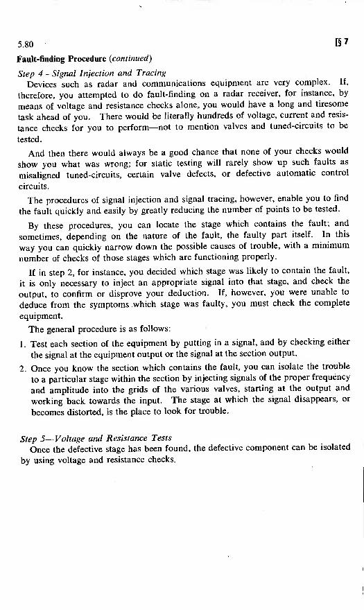
5.80 B 7
Fault-finding Procedure (continued)
Step 4—Signal Injection and Tracing
Devices such as radar and communications equipment are very complex. If,
therefore, you attempted to do fault-finding on a radar receiver, for instance, by
means of voltage and resistance checks alone, you would have a long and tiresome
task ahead of you. There would be literally hundreds of voltage, current and resis-
tance checks for you to perform—not to mention valves and tuned-circuits to be
tested.
And then there would always be a good chance that none of your checks would
show you what was wrong; for static testing will rarely show up such faults as
misaligned tuned-circuits, certain valve defects, or defective automatic control
circuits.
The procedures of signal injection and signal tracing, however, enable you to find
the fault quickly and easily by greatly reducing the number of points to be tested.
By these procedures, you can locate the stage which contains the fault; and
sometimes, depending on the nature of the fault, the faulty part itself. In this
way you can quickly narrow down the possible causes of trouble, with a minimum
number of checks of those stages which are functioning properly.
If in step 2, for instance, you decided which stage was likely to contain the fault,
it is only necessary to inject an appropriate signal into that stage, and check the
output, to confirm or disprove your deduction. If, however, you were unable to
deduce from the symptoms which stage was faulty, you must check the complete
equipment.
The general procedure is as follows:
1 Test each section of the equipment by putting in a signal, and by checking either
the signal at the equipment output or the signal at the section output.
2. Once you know the section which contains the fault, you can isolate the trouble
to a particular stage within the section by injecting signals of the proper frequency
and amplitude into the grids of the various valves, starting at the output and
working back towards the input. The stage at which the signal disappears, or
becomes distorted, is the place to look for trouble.
Step 5—Voltage and Resistance Tests
Once the defective stage has been found, the defective component can be isolated
by using voltage and resistance checks.

§7] 5.81
Fault-finding by Signal Tracing
Signal tracing and signal injection are basically the same thing. Each has someadvantages over the other for the testing of different types of circuit.
The basic purpose of both these methods is to locate the exact area of trouble.
Any break or short in the signal path can be located, because the signal will dis-
appear at that point. If the trouble is due to an incorrect voltage on a valve, or to
a faulty valve, the signal will not pass (or will be distorted) between the grid andanode circuit of the valve. If the trouble is of this nature, it can be localized
immediately to the specific valve; and then the exact fault can be located by voltage
and resistance checks, or by trying a valve known to be a good one.
In the procedure for signal tracing, the normal signal input for a piece of equip-
ment is connected to the input terminals. An oscilloscope or meter is then used to
trace the signal from the input towards the output. The point at which the signal
disappears or becomes distorted is the point to look for the fault.
Signal tracing can be used with practically every type of circuit that you will
come across; but in receivers, the tracing of signals is difficult because of the lowvoltage r.f. signals present in the early stages of the circuit.
Sequence U4ed Ut Su^ud *7*actHy
Fj
H Signal S3GeneratorH H
| Input |
O
/
±11
N| 1 Meter H3 B tn-
^H 1 Oscilloscope M

5.82 [§ 7
Fault-finding by Signal Injection
In the procedure for signal injection, an oscilloscope or output meter is perma-
nently connected to the output of a piece of equipment.
A signal generator is used to inject a signal of the proper amplitude and fre-
quency into the various test points, starting at the output and working towards
the input.
Signal injection is used mainly with receivers, and with other similar equipment
containing high frequency amplifiers whose output cannot easily be checked.
Signal injection solves this problem by using a signal generator to inject signals
into various parts of the equipment. The amplifiers in the equipment under test
will give a large enough gain so that the signal can be observed at the output.
The first stage to check is the last stage of the piece of equipment. If this last
stage is operating normally, the next-to-last stage is checked by feeding a signal
into that stage, and then by checking the output at the same point as before.
It is because you are always observing the output of the equipment as a whole in
signal injection that the last stage in the equipment is the first one to be checked.
Just as in signal tracing, the point where the signal becomes distorted or dis-
appears is the point to look for the fault. The last stage, for example, may be
checked and found correct. So the signal is put on the next-to-last stage; and if
the output of the equipment as a whole then ceases to be normal, you can be sure
that the trouble is in the next-to-last stage.

§ 7] 5.83
Testing Within Stages
Having localized the fault to a single stage, the last step in fault-finding pro-cedure is to make detailed checks within the stage to find the faulty component..The types of test made within stages are:
(i) Voltage and Current Measurements. Equipment handbooks and data sheets
will give correct operating voltages and currents for the stage,
(ii) Resistance and Continuity Tests. Resistances from various points in the stageto earth may be quoted in the equipment handbook. If such information is notgiven, it may be deduced from the circuit diagram.
Where a resistor lies in one of a number of parallel paths, it is better to
disconnect one end before measuring its resistance.
Where the wiring of the stage is suspect, continuity tests with an ohmmetercan be used to find the fault,
(iii) Substitution. It is sometimes more convenient to check whether a componentis fulfilling its function by substituting a known good component.The best example of this is the valve of a suspect stage. Where voltage or
current checks indicate the valve as a possible source of trouble, the substitu-tion of a known good valve will quickly confirm or refute your suspicion.

5.84 [§7
Fault-finding in the Superhet Receiver
Y
V
Detector AFAmplifier
LocalOscillator
a nHeater Voltage HT+Voltage
PowerSupply
1. The Power Supply
A power supply unit consists of at least three stages; mains transformer, rectifier,
and filter. Your procedure for fault-finding should therefore be either:
(i) Check the input and output of each stage, beginning with the a.c. mains input
to the primary; or preferably
(ii) Check from the d.c. output back towards the a.c. mains input.
2. The Audio Amplifier
When fault-finding in the audio amplifier stages of a receiver, it is better to use
the signal injection method, because you will have to use that method for the rest
of the receiver. The 'scope or output meter should be connected across the loud-
speaker at the output transformer secondary. An audio signal is injected into the
various test points from the loudspeaker towards the detector. The point at which
the signal disappears or becomes distorted is the place to look for the fault.
3. The Detector
The detector takes a modulated r.f. (or i.f.) signal and separates the audio from
the r.f. component. The high-frequency component is bypassed to earth and the
audio signal is connected to the audio amplifier.

§7] 5.85
Fault-finding in the Superhet Receiver (continued)
When checking a detector, therefore, the procedure is to inject a modulated r.f.
(or i.f.) signal into the detector input. If an audio signal corresponding to the
modulation does not appear at the output, there is a fault in the detector.
4. The I.F. Amplifier
The i.f. amplifier is an r.f. amplifier operating at a fixed frequency of 465 kc/s.
The operation of the i.f. amplifier is similar to that of the r.f. amplifier described
in the amplifier section—the only difference being that the i.f. amplifier operates at
a fixed frequency, and may for this reason be designed for a much higher gain.
By injecting a modulated 465-kc/s signal, you can first test the i.f. output trans-
former, then the valve, and finally the input transformer. In all cases an audio
signal should appear at the output.
5. The Mixer and the Oscillator
The mixer stage selects the desired modulated r.f. signal from the aerial, andmixes it with the unmodulated signal from the local oscillator. The local oscillator
and the mixer tuning circuit have mechanically-ganged tuning capacitors whichkeep the frequencies of the selected signal and of the oscillator 465 kc/s apart. Asa result of the mixer valve action, a modulated 465-kc/s signal is fed into the i.f.
amplifier no matter what the frequency of the selected r.f. signal.
The mixer is tested by first injecting a modulated 465-kc/s signal into the grid.
If this signal passes through the mixer and appears as an audio signal at the final
output, the mixer valve is operating correctly.
Then a modulated r.f. signal is injected at the same point, and the receiver is tuned
to this signal. An audio signal should appear at the output. If no signal appears,
there is a fault in the oscillator circuit.
The methods of testing an oscillator stage to verify that it is oscillating are
described on page 5.90.
6. The Aerial Input Circuit
If the mixer and oscillator stages are proved correct, the final step is to test the
aerial circuit by injecting a modulated r.f. signal at the aerial input terminal andtuning the receiver. If no audio output is obtained, the fault lies between the input
terminal and the grid of the mixer valve.

5.86 [§ 7
Test Instruments
In the fault-finding procedures described in the preceding pages, a number of
requirements for test instruments have been mentioned. You need not at this stage
know the circuits and principles of the test instruments you will use; but you should
be familiar with the facilities they offer.
Before you attempt to use test instruments in fault-finding, you must be familiar
with the operating instructions issued by the maker, and also know how to inter-
pret the results indicated by the instrument.
The facilities offered by the more common test instruments are summarized below.
R.F. Signal Sources. These are called Signal Generators, and give an r.f. output
whose frequency is variable over a wide range. The output is accurately calibrated
in terms of voltage, but the instrument should not be regarded as an accurate
frequency standard.
The instrument also includes facilities for modulating its own output—either by
amplitude modulation (AM) or by frequency modulation (FM), for which see Part 6.
Frequency Standards. The instrument used to check the frequency of a trans-
mitter or to inject a signal at a precise r.f. frequency into a receiver is called a
Wavemeter or a Frequency Meter. Such an instrument normally has a built-in
calibration checking system.
The wavemeter does not usually provide modulated r.f.
A.F. Sources. The instrument which provides an a.f. signal is called an Audio
Signal Generator. One source of a.f. commonly used is the Beat Frequency Oscil-
lator (BFO).
The output of such instruments can be varied in amplitude and frequency over
the whole of the a.f. range.
Instruments for Tracing Signals. The three instruments most commonly used for
tracing signals are the CRO, the Output Meter, and the Valve Voltmeter. Thefacilities offered by a CRO have already been described in Part 4 of Basic Electricity.
Output Meters. In an output meter, a.f. power is dissipated in a fixed impedance
within the instrument. The a.f. voltage across this fixed impedance is measured
by a meter across a rectifier bridge. The meter is calibrated to read power directly.
The fixed impedance is matched to the output impedance of the circuit in which
the power is being measured by a tapped transformer incorporated in the instrument.
The AVO Model 7, when switched to the power range, can be used as an output
meter of this type.
Valve Voltmeters. Voltmeters of the kind described in Part 1 of Basic Electricity
cannot be used to measure accurately the voltage across very high impedances or
resistances, because of the shunting effect of the meter. In such cases (for example,
when measuring the voltage on the grid of a valve) a valve voltmeter, which itself
has a very high input impedance, is used instead.
#o<> #oooooooo

§ 7] '5.87
Valve Testing
Although it is sometimes convenient to find out whether a valve is functioning
properly in a circuit by substituting for it a known good valve, there will be timeswhen it will be necessary to test valves. For this purpose you will use instrumentsknown as "valve testers."
Since burned-out filaments cause the majority of valve failures, it is usuallypossible to discover such defective valves by removing them from the equipmentand testing them with an ohmmeter.
In general, however, the most satisfactory method of determining whether someof the valve electrodes are shorted, and whether the emission or mutual conductanceare normal for its type, is to use a tester.
Note, however, that the valve tester cannot always be looked on as a final
authority for determining whether or not a particular valve will operate satis-
factorily in a given equipment. This is because the valve might be operating in
the equipment on a portion of its characteristic curve which is not covered in thetester; or it might be operating in the equipment with voltages much higher or muchlower than those used in the tester.
The check for filament continuity and for shorted valve electrodes is generallyperformed as the first part of the testing procedure. If the filament is found to beopen-circuited, it is useless to attempt further testing of that valve. If shortedelectrodes are discovered, it is not advisable to test further, as the shorted electrodesmay blow fuses or damage the tester.
Filament continuity and shorted electrodes are indicated by the lighting of asmall neon or pilot lamp on the instrument panel, or by an indication on a meter.The next step is to test the mutual conductance of the valve. When doing this,
the tester simulates the normal operation of the valve by applying a known signalto the grid, and measuring the strength of the amplified signal in the anode circuitby means of an output meter. Since this procedure is performed under conditionswhich resemble the actual operating of the valve in an equipment, the results ob-tained give a good indication of the valve's serviceability.
Outputmeter
Valve conductance indicated bystrength of amplified signal
Manufacturers supply, in addition to instructions on the use of a valve testertesting data for a very wide range of valves.

5.88 [§7
Some Examples of Fault-finding in the Superhet
Let us now go through the correct procedure to locate four typical faults in the
superhet receiver.
The first fault is an open-circuited coupling capacitor between the anode of the
first a.f. amplifier and the grid of the output valve.
When an audio signal is applied to the grid of V-4, an output will be observed
on an oscilloscope or output meter. When an audio signal is applied to the grid
of V-3, no output signal is observed.
Using a 001 -pF blocking capacitor in the lead from the audio signal generator
(in order to prevent H.T. being fed back and damaging the a.f. generator), apply the
signal to the anode of V-3. No signal is observed at the output. The fault area is
therefore between the anode of V-3 and the grid of V-4.
The coupling capacitor is immediately suspected, as it is the only a.c. connecting
link between anode and grid. Substitution of a known good capacitor will show
that the fault has been cleared.
AUDIO SIGNAL SCOPE PICTURE
POINT©POINT (2
C/RCUITJ CONCLUSION
The second fault is a short to earth (chassis) from the slider of the volume control.
Using signal injection, an output is observed when an audio signal is placed on
the grid of V-4 and the anode of V-3. The same signal applied to the grid of V-3
also produces an output.
SCOPE PICTURE

§7] 5.89
Some Examples of Fault-finding in the Superhet (continued)
It is as well at this point to check the action of the volume control. Injecting
the a.f. signal at the top-end of the volume control results in no output, and rotating
the control has no effect. With the receiver switched off, a resistance check from
the potentiometer slider to earth reads zero with the control in any position. This
proves that the slider is shorting to earth.
A visual inspection of the component may reveal the fault, or failing that a
replacement volume control will restore the receiver to a working condition.
The third fault is a short-circuited i.f. trimmer capacitor.
By injecting modulated signals, it is found that when a 465-kc/s signal is applied
to the detector anodes of V-3 an output is observed. Injecting a modulated signal
of 465 kc/s on to the grid of V-2, however, gives no output. Applying a signal to
the anode of V-2 (through a d.c. blocking capacitor) still gives no output. The
fault has then been isolated to the i.f. amplifier stage V-2.
The valve is replaced, but the fault still remains.
Next, d.c. voltage readings are taken, which appear quite normal. Suspicion is
now localized to the i.f. transformer.
The receiver is switched off, and a resistance check is made from anode to
H.T.(+). The result is a reading of zero, instead of the correct reading of 6 ohms.
This confirms that the i.f. transformer is faulty.
A replacement transformer, after being correctly aligned to 465 kc/s, would cure
the fault; but if a new ii. transformer is not available, it is necessary to remove the
screening can from the faulty one and (by disconnecting the trimming capacitor from
the coil) to check by resistance measurement whether the capacitor or the coil is
short circuited.
In this case it is a faulty capacitor—and replacement of this component is much
cheaper than is the cost of a complete i.f. transformer.
RB RF SIGNAL SCOPE PICTURE
0®Us!
IRfl 465k<ys
kSS powt (2)
B SI RESISTANCE READING
^^.^ ^PT@TO PT(3) On
m ^ coN(FUSION

5.90 [§7
Some Examples of Fault-finding in the Superhet {continued)
The fourth fault is an unserviceable local oscillator valve.
Signal injection shows that a modulated 465-kc/s signal applied to the control
grid of the mixer valve V-l gives an output. A modulated 1000-kc/s signal applied
to the same point, however, gives no output when the tuning capacitor is varied
over its range.
If the oscillator V-5 were working properly there would be a point, as its tuning
capacitor was varied over the tuning range, at which the difference between the
oscillator frequency and the applied modulated signal of 1000 kc/s would be465 kc/s; and this would pass through the superhet and be observed at the output.
Since no signal appears, however, the oscillator stage is suspect.
Three methods which can be employed to verify if an oscillator stage is
oscillating are:
1. Disconnect the earthy end of the grid resistor and check if there is any d.c.
grid current, using a suitable milli- or micro-ammeter.
2. Check if there is any d.c. voltage on the grid of the valve.
3. Check if there are a.c. oscillations present at the grid or anode of the valve.
Checks (2) and (3) above have to be carried out with a valve voltmeter. Theimpedances from grid to earth, and from anode to earth, in an oscillator circuit are
high. The input impedance of a meter such as the AVO 7 is comparatively low;
and if such a meter were connected to an oscillator circuit, it would shunt the anodeor grid circuit—thus seriously impairing the performance of the oscillator, or even
stopping it oscillating altogether.
The valve voltmeter, however, has a high input impedance; so it can be connected
to an oscillator circuit without these adverse effects.
Using any of the three methods given, the result in the case we are considering
would be:
The most likely
1. No grid current.
2. No d.c. voltage on the grid.
3. No oscillations at the anode; so the stage is not oscillating,
cause is a faulty valve.
A change of valve will therefore make the receiver operative in this particular case.
RF SIGNAL 1 SCOPE PICTURE
POINT(J)
465 kc/S
POINT (T)lOOOkc/s
DC VOLTAGECHECK
POINT (2
READNG
OV
CONCLUSION

§7]
REVIEW—Fault-finding
5.91
The correct sequence of steps in fault-finding is as follows:
(i) Collate the symptoms of the fault.
(ii) Consider the symptoms and deduce a possible cause,
(iii) Inspect the equipment for obvious defects.
(iv) Test the suspect stage (or every stage in the equipment if the symptoms
do not lead you to suspect one particular stage).
(v) Having located the faulty stage, make voltage, current and/or resistance
checks to detect the faulty component.
(vi) Replace the faulty component and check that the equipment is operating
normally.
Steps in Fault Finding
1. Isolate defective staqe by siqnal injection.2. Check d.c. voltaqes from valve pins to earth.3. Check resistance from valve pins to earth.
As you gain experience in fault-finding, you will be able to make more use of the
evidence and will have to test fewer stages before you find the faulty one.
Fault-finding is not a matter of gambling on a chance—it is a matter for logical thought.

5.92 §8: GENERAL REVIEW OF RECEIVERS
Aerial. The purpose of a receiving aerial
is to pick up electro-magnetic waves radiated
by transmitting aerials. These waves, in
cutting the aerial, induce voltages in it, causing
currents to flow. The currents flow into the
input of the receiver, where they generate
signals which are amplified by the receiver
circuits.
Electromagnetic Waves
lllllli»M|||ll
V)) jvy
TRANSMITTER
Directional Characteristics. The position
of a receiving aerial relative to the transmitting
aerial will determine the strength of signal
picked up. If the frame aerial of a receiver
is parallel to the frame aerial of a transmitter,
the signal picked up will be of maximumamplitude. If the receiving aerial is turned so
that its edge faces the broad side of the trans-
mitting aerial, a very weak signal will be picked
up. Therefore, the aerial is said to have
directional characteristics.
R.F. Amplifier Stage. An r.f. amplifier
stage in a receiver improves the sensitivity and
selectivity of the receiver. The added sensi-
tivity results from the amplification of the
desired signal, and the added selectivity
results from the use of tuned-circuits which
discriminate between the desired and undesired
signals.
Audio Amplifier Stage. An audio amplifier
stage in a receiver amplifies the detected audio
signal. Audio stages, which precede the last
stage, are voltage amplifiers whose sole
function is to increase the amplitude of the audio
to the level where it is large enough to drive the
last stage. The last stage, called the "power out-
put stage," supplies the large current variations
necessary to drive the loudspeaker.
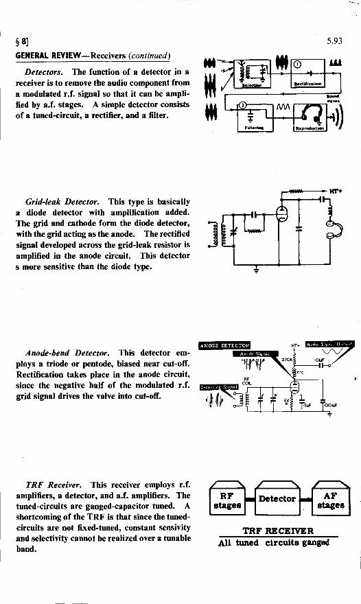
§8]
GENERAL REVIEW-
5.93
-Receivers (continued)
Detectors. The function of a detector in a
receiver is to remove the audio component from
a modulated r.f. signal so that it can be ampli-
fied by a.f. stages. A simple detector consists
of a tuned-circuit, a rectifier, and a filter.
Grid-leak Detector. This type is basically
a diode detector with amplification added.
The grid and cathode form the diode detector,
with the grid acting as the anode. The rectified
signal developed across the grid-leak resistor is
amplified in the anode circuit. This detector
s more sensitive than the diode type.
Anode-bend Detector. This detector em-
ploys a triode or pentode, biased near cut-off.
Rectification takes place in the anode circuit,
since the negative half of the modulated r.f.
grid signal drives the valve into cut-off.
TRF Receiver. This receiver employs r.f.
amplifiers, a detector, and a.f. amplifiers. The
tuned-circuits are ganged-capacitor tuned. Ashortcoming of the TRF is that since the tuned-
circuits are not fixed-tuned, constant sensivity
and selectivity cannot be realized over a tunable
band.
' s y \ / \RF
stagesDetector AF
stages
rrRF RECEfVEFAll tuned circuits ganged
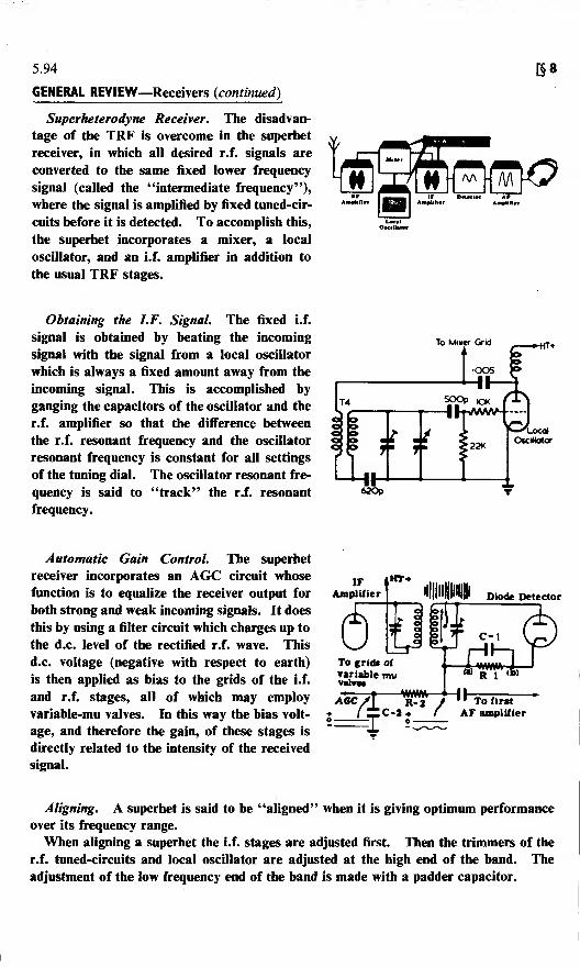
5.94
GENERAL REVIEW—Receivers (continued)
Superheterodyne Receiver. The disadvan-
tage of the TRF is overcome in the superhet
receiver, in which all desired r.f. signals are
converted to the same fixed lower frequency
signal (called the "intermediate frequency"))
where the signal is amplified by fixed tuned-cir-
cuits before it is detected. To accomplish this,
the superhet incorporates a mixer, a local
oscillator, and an i.f. amplifier in addition to
the usual TRF stages.
[§8
1*1....
\Wnr
AmptafUr imlH
Obtaining the I.F. Signal. The fixed i.f.
signal is obtained by beating the incoming
signal with the signal from a local oscillator
which is always a fixed amount away from the
incoming signal. This is accomplished by
ganging the capacitors of the oscillator and the
r.f. amplifier so that the difference between
the r.f. resonant frequency and the oscillator
resonant frequency is constant for all settings
of the tuning dial. The oscillator resonant fre-
quency is said to "track" the r.f. resonant
frequency.
To Mixer Grid
620p
Automatic Gain Control. The superhet
receiver incorporates an AGC circuit whose
function is to equalize the receiver output for
both strong and weak incoming signals. It does
this by using a filter circuit which charges up to
the d.c. level of the rectified r.f. wave. This
d.c. voltage (negative with respect to earth)
is then applied as bias to the grids of the i.f.
and r.f. stages, all of which may employ
variable-mu valves. In this way the bias volt-
age, and therefore the gain, of these stages is
directly related to the intensity of the received
signal.
IFAmplifier
iHT*
Diode Detector
;—Lj
c-'t fTo first
AF amplifier
Aligning. A superhet is said to be "aligned" when it is giving optimum performance
over its frequency range.
When aligning a superhet the i.f. stages are adjusted first. Then the trimmers of the
r.f. tuned-circuits and local oscillator are adjusted at the high end of the band. The
adjustment of the low frequency end of the band is made with a padder capacitor.

§9: MISCELLANEOUS ELECTRONIC CIRCUITS 5.95
Most of the very large number of electronic circuits which have been devised to
perform an almost bewildering variety of duties in modern industry and modern
defence equipment employ principles already familiar to you from your study of
the three-stage transmitter and the superhet receiver.
They can nearly all be understood if you remember the principles of the three
basic valve circuits—the rectifier, the amplifier, and the oscillator.
THESE ARE BASIC TO ALL ELECTRONIC EQUIPMENT
glliliS^*^
Here are three particular circuits you are likely to meet in working with electronic
equipment:
(i) The cathode follower,
(ii) A typical time-base generator,
(iii) A typical voltage stabilizer.

5.96
The Cathode Follower
The circuit of the cathode follower is illustrated below:
-HT+
B»
*-HT-
The input signal is applied between grid and earth, and the output taken fromacross the resistor in the cathode of the valve. The undecoupled cathode intro-duces negative feedback; so the output signal (which is the fluctuating componentof the cathode current) is in opposition to the incoming signal.
Fout is a faithful reproduction of KiN , but is of lower amplitude.In other words, the cathode follows the grid—hence the name of the circuit.
A cathode follower has the following properties:
1. The voltage gain is always less than one (normally of the order of 0-9). That is
to say, the cathode follower does not amplify the input signal.
2. The circuit has a low output resistance and a high input resistance.
You will find cathode followers in use where it is necessary to match a highimpedance into a low impedance without the need of amplification. Such a systemwould be required if the output of an amplifier of, say, 1-megohm output impedancewas required to feed into a cable of 300-ohm impedance. The .cathode followerwould be inserted between the amplifier and the cable.
You saw, when you were learning about video amplifiers, how important it wasto maintain a good square or rectangular waveform. One use of the cathodefollower is to maintain a waveform shape while at the same time matching twoimpedances.

§9]5.97
A Typical Time-base Generator
A time-base generator generates the voltage which is applied to the X plates of a
CRO, with the object of causing the spot to move from left to right across the tube,
and then to fly back again. The voltage waveform required for this purpose is
illustrated in the first diagram below.
Voltage applied j)k
to X plates
Time«« *^v^-| /^Fly back time
Time occupied by sweep \J_/
Now consider the simple circuit illustrated below:
-&**£ »-HT+
Voltage
applied to
X plates
*-HT-
The valve is a gas-filled triode, similar to the gas-filled diode described in Part 1
of Basic Electronics except that its striking voltage can be controlled by varying
the negative potential on its grid.
When H.T. is applied to the circuit, the capacitor C begins to charge through
the resistor R. It continues to charge until the voltage across C—and therefore
across the gas-filled triode—reaches the valve's striking voltage, which is in turn
controlled by the negative potential on the grid.
Once the valve has struck, its resistance becomes negligible; and C discharges
through resistor r and the valve.
This process is repeated, the gas-filled valve remaining cut-off until its striking
voltage is reached again.
The time-constant for charging the capacitor (RC) and the time-constant for dis-
charging the capacitor (rC) are very different; and the output waveform across C is
as illustrated below.
*-T
You can see that the waveform of this voltage is not identical with the ideal
time-base voltage waveform illustrated above. A circuit whose output approaches
more nearly to the ideal is described on the next page.

5.98
A Typical Time-base Generator {continued)
the cir<
[§9
The output voltage of the circuit illustrated below is the voltage across thecapacitor C.
-*~HT+
Synch
*~HT-
When H.T. is applied to the circuit, C begins to charge, its charging currentflowing through the pentode V-l.
You have already learnt that the current through a pentode is constant over awide range of anode voltages. The magnitude of the current through the pentodeis determined by the voltages applied to the control grid and screen of the valve.Therefore the pentode acts as a constant current device, and C charges at a linearrate.
When the voltage across C reaches the striking voltage of the gas-filled triode V-2,this valve strikes; and C discharges rapidly.
The process is repeated, producing the "saw-tooth" output illustrated below.
The control P varies the grid voltage of V-l, and therefore controls the currentthrough V-l and through capacitor C. It therefore controls the slope of the saw-tooth waveform.
The control Q varies the striking voltage V-2, and therefore the amplitude ofthe saw-tooth waveform.

§9] 5.99
A Typical Voltage Stabilizer Circuit
In Part 1 of Basic Electronics you learnt how gas-filled diodes could be used to
stabilize the output of a power-supply unit.
The output voltage of a power supply unit using gas-filled diodes as stabilizers
is, however, only stable within narrow limits—principally because of the current
limitations of gas-filled valves.
A stabilizer circuit which will operate between wider limits is illustrated below.
+ 6UnstabHiscd
6 +Stabilised
dc output
voltage
If the output voltage in the above circuit increases, the voltage at the grid of V-2
will increase also, since it is taken from a resistance-chain across the output. This
will cause an increase of current through V-2, and the voltage at its anode will
decrease. This anode is connected directly to the grid of V-l, which acts as a
variable resistance.
As the voltage on the grid of V-l is decreased—that is to say, made more negative
—the current through V-l is reduced, and the output voltage is restored to its
previous value.
Similarly, if the output voltage falls, the "resistance" of V-l is decreased, current
through the valve increases, and the output voltage attains its correct value.
The variable control VR-1 determines the voltage applied to the grid of V-2, and
hence determines the value of the stabilized d.c. output voltage.
The gas-filled diode V-3 keeps the cathode V-2 at a constant potential, so that
only changes at the grid of V-2 affect the current through V-2—and therefore the
"resistance" of V-l.
You will learn more about these and other special circuits when you get on to
your study of Basic Radar.

s.100 §10: FREQUENCY MODULATION:TRANSISTORS
You have now completed your study of the basic circuits used in electronics:
namely, rectification and amplification. You have also learnt how the valve ampli-
fier can be used as an oscillator, and you have seen how all these circuits can be
combined to form an AM wireless communications system.
Before you leave what may be called the "Basic Fundamentals Area" of this
fascinating subject, however, and pass on to the study of such practical applications
as Telecommunications Equipment, Radar, Echo-sounding, Fire Control Equip-
ments, Missile Guidance Systems, or Servo-mechanisms, you should first learn
something of two other subjects: Frequency Modulation and Transistors.
Frequency Modulation (or FM, as it is usually abbreviated) can be simply
described as another method of modulating wireless waves in order to transmit
intelligence. In this method of modulation, the frequency of the carrier wave is
varied at a rate depending on the frequency of the modulating wave, and to an
extent depending on the amplitude of the modulating wave. This method of modu-lation offers some advantages over AM, particularly in the matter of freedom fromstatic interference; and it is being increasingly used in commercial and military
communication networks.
Transistors were invented as recently as 1948—by three American scientists,
Shockley, Brattain and Bardeen. They are being used to replace valves in manyelectronic circuits; since they
offer economies in space,
weight and power output
which make them very suitable
for use in equipments where
these factors are of import-
ance.
It is these two new topics
—
Frequency Modulation and
Transistors—which form the
subject-matter of Part 6 of
Basic Electronics.
Part 6
FREQUENCY MODULATION
AND
TRANSISTORS

INDEX TO PART 5
(Note: A cumulative index covering all six Parts in this series will be found at the end of
Part 6)
Aerials, receiver, 5.13, 5.20
selecting and installing, 5.16
types of, 5.14
A.F. amplifier, 5.41
in the superhet receiver, 5.57, 5.67
in the TRF receiver, 5.38, 5.42
tone control, 5.39
volume control, 5.40
Alignment, 5.68, 5.71, 5.72
Anode-bend detector, 5.35
Automatic gain control (AGC), 5.58
Band switching in receivers, 5.24
Capacitors
gauged, 5.25
padder, 5.65, 5.73
trimmer, 5.26, 5.72
Cathode follower, 5.96
Crystal detector, 5.30
Crystal receiver, 5.10
Detector, 5.37
anode-bend, 5.35
crystal, 5.30
diode, 5.32
grid-leak, 5.33
in the superhet receiver, 5.57, 5.67
in the superhet receiver for CWworking, 5.64
in the TRF receiver, 5.29
Diode detector, 5.32
Fault finding, 5.76, 5.91
in the superhet receiver, 5.84
procedure, 5.77
signal injection, 5.82
signal tracing, 5.81
testing within stages, 5.83
Fidelity, in a receiver, 5.9
Frequency changing valves, 5.54
Grid leak detector, 5.33
Heterodyne principle, 5.63
].F. amplifier, 5.56, 5.66
I.F. transformer, 5.55
Local oscillator, 5.49, 5.65
Mixing, 5.52
mixer stage in the superhet receiver, 5.53,
5.66
mixer valves, 5.54
Oscillator, beat frequency, 5. 64
Oscillator stage in the superhet receiver,
5.65
Receiver, 5.92
crystal, 5.10
fidelity, 5.9
introduction to, 5.1
selectivity, 5.8, 5.46
sensitivity, 5.7
superhet, 5.12, 5.43, 5.61, 5.74
the jobs performed by, 5.5
TRF, 5.11, 5.21
R.F. amplifier, 5.41
in the superhet receiver, 5.47
in the TRF receiver, 5.22, 5.28
R.F. transformer, 5.23
Selectivity in a receiver, 5.8, 5.46
Sensitivity in a receiver, 5.7
measurements, 5.69
Superhet receiver, 5.12
complete circuit of, 5.61
fault-finding in, 5.84
Test instruments, 5.86
Time base generator, 5.97
Tone control, 5.39
TRF receiver, 5.11, 5.21
Valve testing, 5.87
Voltage stabilizer circuit, 5.99
Volume control
automatic (AGC), 5.58
manually operated, 5.27, 5.40
WIGANCENTRAL]LIBRARY.

621