Basic Design Controls - Connecticut · Basic Design Controls 1.2‐1 SECTION 1, CHAPTER 2 Basic...
42
Basic Design Controls 1.2‐1 SECTION 1, CHAPTER 2 Basic Design Controls 2.1 Introduction Basic design controls serve as the foundation for establishing the physical form, safety, and functionality of the transportation facility. Some design controls are inherent characteristics of the facility (e.g., its physical context and the existing transportation demands placed upon it). Other basic design controls are selected or determined by the designer, working with communities and users to address a project’s purpose and need. Selecting appropriate values or characteristics for these basic design controls is essential to achieve a safe, effective, and context sensitive design. This chapter illustrates these basic design controls and their influence on the physical characteristics of a roadway or other transportation facility: Roadway Context (Section 2.2) Roadway Users (Section 2.3) Transportation Demand (Section 2.4) Measures of Effectiveness (Section 2.5) Speed (Section 2.6) Sight Distance (Section 2.7) 2.2 Roadway Context The context of a roadway is a critical factor to consider in developing a project’s purpose and need, making fundamental design decisions such as cross‐section determination, and selecting detailed design elements such as street light fixtures or other construction materials. Development of a roadway design that is sensitive to, and respectful of, the surrounding context is important for project success. As described in Chapter 1, context‐sensitive design refers to both the process and its results. An open community process that begins early in project development is needed to ensure that there is consensus about a project’s purpose and need. This process needs to continue through the design phase so that the features of the project are assembled to
Transcript of Basic Design Controls - Connecticut · Basic Design Controls 1.2‐1 SECTION 1, CHAPTER 2 Basic...

Basic Design Controls 1.2‐1
SECTION 1, CHAPTER 2
Basic Design Controls
2.1 Introduction
Basicdesigncontrolsserveasthefoundationforestablishingthephysicalform,safety,andfunctionalityofthetransportationfacility.Somedesigncontrolsareinherentcharacteristicsofthefacility(e.g.,itsphysicalcontextandtheexistingtransportationdemandsplaceduponit).Otherbasicdesigncontrolsareselectedordeterminedbythedesigner,workingwithcommunitiesanduserstoaddressaproject’spurposeandneed.Selectingappropriatevaluesorcharacteristicsforthesebasicdesigncontrolsisessentialtoachieveasafe,effective,andcontextsensitivedesign.Thischapterillustratesthesebasicdesigncontrolsandtheirinfluenceonthephysicalcharacteristicsofaroadwayorothertransportationfacility: RoadwayContext(Section2.2) RoadwayUsers(Section2.3) TransportationDemand(Section2.4) MeasuresofEffectiveness(Section2.5) Speed(Section2.6) SightDistance(Section2.7)
2.2 Roadway Context
Thecontextofaroadwayisacriticalfactortoconsiderindevelopingaproject’spurposeandneed,makingfundamentaldesigndecisionssuchascross‐sectiondetermination,andselectingdetaileddesignelementssuchasstreetlightfixturesorotherconstructionmaterials.Developmentofaroadwaydesignthatissensitiveto,andrespectfulof,thesurroundingcontextisimportantforprojectsuccess.AsdescribedinChapter1,context‐sensitivedesignreferstoboththeprocessanditsresults.Anopencommunityprocessthatbeginsearlyinprojectdevelopmentisneededtoensurethatthereisconsensusaboutaproject’spurposeandneed.Thisprocessneedstocontinuethroughthedesignphasesothatthefeaturesoftheprojectareassembledto
1.2‐2 Basic Design Controls
produceanoverallsolutionthatsatisfiestheproject’spurposeandneed,respectssurroundingresources,andisconsistentwithcommunityvalues.Historically,thehighwayorintersectiondesignprocesshasfocusedonaproject’stransportationelements,particularlythoseassociatedwithmotorvehicletravel.Acontext‐sensitivedesignshouldbeginwithanalysisofthecontextualelements,suchasenvironmentalandcommunityresources,oftheareathroughwhicharoadwaypasses.Asdescribedlaterinthischapter,theconceptofareatypeshasbeendevelopedtohelpthedesignerunderstandtheusers,constraints,andopportunitiesthatmaybeencounteredindifferentsettings.Oncethedesignerhasanunderstandingoftheareasurroundingtheroadandtheroad’susers,thedesignershouldconsiderthetransportationelementsoftheroadway,itsfunctionwithintheregionaltransportationsystem,andtheappropriatelevelofaccesscontrol.Thus,threemainelementsofcontextareconsideredindesign: AreaType—thesurroundingbuiltandnaturalenvironment
RoadwayType—theroletheroadwayplaysintermsofprovidingregionalconnectivityandlocalaccess
AccessControl—thedegreeofconnectionorseparationbetweentheroadwayandthesurroundinglanduse
2.2.1 Area Types
Thecontextofaroadwaybeginswithitsenvironmentalcontext,whichincludesnearbynaturalresources,terrain,andthemanmadeenvironment(developmentpatterns,historic,cultural,andrecreationalassets).Theenvironmentalcontextcanbeadeterminantofthedesiredtypeofaccommodationfordifferentusers.Thiscontextoftenestablishesthephysicalconstraintsoftheroadwayalignmentandcross‐section,andinfluencestheselectionofmotorvehicledesignspeed.ThroughoutthisPlan,thisenvironmentalcontextisgeneralizedasareatype.Aroadwayfrequentlytraversesavarietyofchangingenvirons.Additionally,thevolumeandcharacterofpedestrian,bicycle,publictransit,andmotorvehicleactivitycanchangeconsiderablyalongitsroute.Landuseisthefundamentaldeterminantinthefunctionofaroad;aslandusechangesalongaroad,theroad’sfunctionsalsochange.Roadwaysmustbedesignedinamannerthatservestheexistinglandusewhilesupportingthecommunity’sfuturelandusegoals.Traditionally,roadwayshavebeenclassifiedeitheras“rural”or“urban.”Itisimportanttorecognizethataroadway’sformalclassificationasurbanorrural(whichisdeterminedfromcensusdatausingperiodically‐adjustedcriteriaadoptedbytheUnitedStatesOfficeofManagementandBudget)maydifferfromactualsitecircumstancesorprevailingconditions.Anexampleincludesanurbanarterialroutepassingthrougha

Section 1, Chapter 2
Basic Design Controls 1.2‐3
portionofNorwalk.Theroutemaynotnecessarilybeclassifiedassuburban,buttheremaybeasignificantlengthoverwhichthesurroundinglanduse,prevailingspeeds,andtransportationfunctionsaremoresuburbanthanrural.Forthisreason,itisimportantforthedesigner,workingwiththecommunityandprojectreviewers,todetermineanappropriateareatypeortypesforaprojectearlyintheplanningprocess.AsmentionedinChapter1,theCityofNorwalkisverydiverseinitscharacter.AreatypesareillustrativeofthebroadrangeofenvironmentsthatthedesignermayencounterthroughouttheCity.Thedesignershouldalsoidentifyuniqueorproject‐specificcontextualelementsthatwillinfluencethedesignbeyondthosegeneralizedforthefollowingareatypes.Thesemightinclude,asexamples,schools,churches,historicfeatures,environmentalresources,areabikefacilities,beachandrecreationalareas,sidewalks,andbusstops.
2.2.1.1 Rural Area Types
Ruralareasaregenerallyundevelopedorsparselysettledwithdevelopmentatlowdensitiesalongasmallnumberofroadwaysorclusteredinsmallvillages,asillustratedinExhibit2‐1.Ruralareasareoftendistantfromlargemetropolitancenters.Therearenotverymany‘rural’areaswithintheCityofNorwalk.
2.2.1.2 Suburban Area Types
Suburbanareasvarywidelyincharacterandareusuallyfoundoutsidethecoreofametropolitanarea.Somecomponentsofsuburbanzonesmayappearruralincharacter,whileothersaredenselypopulatedandmorecloselyresembleurbanareas,asillustratedinExhibit2‐2.Threedifferentareatypescharacterizethesuburbancontextzone.MuchofNorwalkcanbeconsidered‘suburban’innature.
2.2.1.3 Urban Area Types
Urbanareasaretypicallyfoundatthecoreofametropolitanarea.Inmanycases,theurbanareaincludesacentralbusinessdistrict(CBD)withhighdensitycommercialandresidentialdevelopmentsurroundingtheCBD.WhileNorwalkdoesn’thavemany,ifany,traditionalurbanlocationstherearesomeareaswhichexhibit‘urban’characteristics.Openspaceisgenerallyfoundinformalparksorurbanpreserves,asillustratedinExhibit2‐3.Althoughindividualareatypesaredescribedbelowtoillustratethelandusevariationsfoundintheurbanarea,theroadwayelementsdescribedinthesubsequentchaptersrecognizethataconsistentdesignapproachistypicallyappliedtourbanareasgiventhesimilaritiesinparcelaccess,pedestrianactivity,bicycleactivity,andtransitavailabilityacrosstheselandusevariations.

1.2‐4 Basic Design Controls
Exhibit 2‐1 Rural Area Types
Source: MassDOT

Section 1, Chapter 2
Basic Design Controls 1.2‐5
Exhibit 2‐2 Suburban Area Types
Source: MassDOT

1.2‐6 Basic Design Controls
Exhibit 2‐3 Urban Area Types
Source: MassDOT

Section 1, Chapter 2
Basic Design Controls 1.2‐7
2.2.2 Roadway Types
Thetransportationnetworkiscomposedofseveraldifferenttypesofroadwaysthatprovidedifferentfunctions,traditionallyreferredtoasait’sfunctionalclass(orclassification).Theprimarypurposeofsomeroadsistofacilitatemovementofvehicles(bicycles,cars,trucks,busesandlightrail)betweenpartsofthecommunity.Theprimarypurposeofotherroadsistoprovideaccesstotheadjoiningland.Mostroadsprovideacombinationofthesepurposes,asillustratedinExhibit2‐4.Roadwaytype,definedbythefacility’sroleinthestateandregionaltransportationsystem,togetherwithitsareatype,isanimportantcontextualconsiderationfordesign.Theroadwaytypeshouldbeselectedtoreflecttheactualrolethattheroadwayplaysinthetransportationsystem,asdefinedthroughtheprojectdevelopmentprocess.Atypicaltripwilloftenentailtravelingalongavarietyofroadwaytypes,eachofwhichprovidesadifferentdegreeoflocalaccessandadifferentdegreeofregionalconnectivity.Norwalkisnoexceptiontothiswithmultipleregionalandlocalroadwayscriss‐crossingthecommunity.TheroadwaytypereflectsitsdegreeoflocalaccessandregionalconnectivityasillustratedschematicallyinExhibit2‐5anddescribedbelow: Freewaysareprimarilyforinterstateandregionaltravel(highregional
connectivityathighspeedswithlimitedaccesstoadjacentlandandlimitedaccessforpedestriansandbicyclists).Interstate‐95,theMerrittParkway,andpartsoftheRoute7corridorarethreeexamplesoffreeway‐typeroadwayswithinNorwalk.
Majorarterialsservicestatewidetravelaswellasmajortrafficmovementswithinurbanizedareasorbetweensuburbancenters(highregionalconnectivityatawiderangeofspeeds,andalowerleveloflocalaccessthanthefollowingroadwaytypes).Route1andpartsofRoute7bothserveasmajorarterialsthroughNorwalkastheyconnectthecommunitywithbothregionalandnearbycommunities.
Minorarterialslinkcitiesandtownsinruralareasandinterconnectmajorarterialswithinurbanareas(hightomoderateregionalconnectivityatawiderangeofspeeds,andmoderatedegreesoflocalaccess).
Majorcollectorslinkarterialroadwaysandprovideconnectionsbetweencitiesandtowns(moderatetolowregionalconnectivityatawiderangeofspeeds,andhigherdegreeoflocalaccessthanarterialsandfreeways).
Minorcollectorsconnectlocalroadstomajorcollectorsandarterials(lowerregionalconnectivityatlowerspeedsandhigherdegreesoflocalaccessthanthepreviousroadwaytypes).
Localroadsandstreets—Notintendedforregionalconnectivity(lowspeedswithahighdegreeoflocalcirculationandaccess).

1.2‐8 Basic Design Controls
Exhibit 2‐4 Conceptual Framework of Roadway Type
Source: Adapted from Safety Effectiveness of Highway Design Features, Volume 1, Access Control, FHWA, 1992
Exhibit 2‐5 Schematic Representation of Roadway Type
Source: MassDOT

Section 1, Chapter 2
Basic Design Controls 1.2‐9
2.2.2.1 Relationship to the Formal Functional Classification System
ThefunctionalclassificationsystemdevelopedbytheFederalHighwayAdministrationandappliedtoallroadwaysintheUnitedStatesremainsakeyelementofsystemplanningsothatasafeandefficienttransportationnetwork,providingthedesiredlevelofregionalconnectivityandlandaccess,isdevelopedandmaintained.Thisclassificationsystemisalsousedasadeterminateoffederalfundingeligibility.Formalfunctionalclassificationsinclude:Interstate,PrincipalArterial,RuralMinorArterialorUrbanPrincipalArterial,RuralMajorCollectororUrbanMinorArterial,andRuralMinorCollectororUrbanCollector.Thisformalclassificationoftenservesasausefulstartingpoint,butthedesignershouldnotsimplyrelyonthisformaldesignationasadesigncontrol.Theroadwaytypeshouldbeselectedtoreflecttheactualrolethattheroadwayplaysinthetransportationsystem,asdefinedthroughtheprojectdevelopmentprocess.Forexample,aroadwaymayserveahighnumberofregionaltrips,butmaypassthroughaportionoftownwithfrequentdriveways,closeintersectionspacing,andhighlevelsofpedestrianactivity.Inthiscase,theroadwayservesasbothanarterialANDalocalroad.Thedesignershouldworkcloselywiththecommunitytodeterminetheroadwaycharacteristicsandappropriatedesignconsiderationstoserveboththeregionalpurposeoftheroadwayanditsroleinthelocalsetting.
2.2.3 Access Control
Accesscontrolisatermusedtodefinehowaccesstoadjacentpropertiesisregulatedanddesignedalongaroadway.Accesscontrolisamongthemostusefultoolsavailabletomaintainsafeandefficientroadwayoperationsforallusers.Judicioususeofmediantreatments,drivewaypermits,drivewayconsolidationandsafedrivewaygeometrycanimproveroadwaysafetyandenhancetheoperationoftheroadwithoutundueburdenonaccessingborderingproperty.Thedegreeofaccesscontrolisinfluencedbytheroadwaytypeandareatype.Forexample,accesscontrolsareusuallymorestringentonarterialsthanoncollectorsandlocalroads,reflectingthemobilityandlandaccessfunctionsoftheseroadways.Likewise,accesscontrolsareoftengivenmoreconsiderationindevelopingareaswherethereisflexibilityforfuturelandusetoconformtoanaccessmanagementplanthanindevelopedareaswherethepatternoflandusehasbeenestablished.However,thedesignershouldconsiderexistingaccesspointsalongaroadwayandthepossibilityforchangesthatareconsistentwiththeproject’spurposeandneed.Forexample,itmaybepossibletorelocate,redesign,orconsolidatedrivewaysalonganexistingroadway.Athoroughunderstandingofaccesscontrolwillhelpthedesignerselectanappropriatedesignspeed,planningparameters,anddesiredlevel‐of‐serviceforthefacility’susers.Accesscontrolisexercisedbystatute,zoning,right‐of‐waypurchases,drivewaycontrols,turningandparkingregulations,geometricdesign(e.g.,raisedmedians,gradeseparations,andfrontageroads),andlocalrightofwaypermitting,administeredbythe

1.2‐10 Basic Design Controls
ConnecticutOfficeofStateTrafficAdministration(OSTA),localPublicWorksDepartmentsorthePlanningandZoningCommission.Roadwayscanbedesignedwiththefollowingapproachestoaccesscontrol: FullControl—Fullcontrolgivesprioritytothroughtrafficbyprovidingaccessonlyat
grade‐separatedinterchangeswithselectedpublicroads.Noat‐gradecrossingsorprivatedrivewayconnectionsareallowed.“Freeway”isthecommontermusedforthistypeofhighway.Fullaccesscontrolmaximizesthecapacity,safety,andspeedsonthefreeway.
PartialControl—Partialcontrolofaccessisanintermediatelevelbetweenfullcontrolandregulatoryrestriction.Underpartialcontrolofaccess,priorityisgiventothroughtraffic,butafewatgradeintersectionsandprivatedrivewayconnectionsmaybeallowed.Partialcontrolofaccessmaybeprovidedforcertainarterialandcollectorroadways.Theproperselectionandspacingofat‐gradeintersectionsandserviceconnectionswillprovideasafebalancebetweentheregionalconnectivityandlocalaccessfunctionsofthefacility.
Statute,ZoningandRegulation—Ifaccesspointsareproperlyspacedanddesigned,theadverseeffectsonroadwaycapacityandsafetywillbeminimized.Thedesignshouldenablevehiclestoenterandexitsafelywithaminimumofinterferencetothroughtraffic.Statutorycontrolmaybeused,forexample,onaruralorurbanarterialhighwaytolimitaccessonlytopublicroadcrossings.Drivewayregulationsandpermitsareoftenusedtocontrolthegeometricdesignofanentrance,drivewayspacing,anddrivewayproximitytopublicroadintersections.Zoningmayalsobeusedtoeffectivelycontroltheadjacentpropertydevelopmentsothatmajorgeneratorsoftrafficwillnotdevelop;however,zoningregulationsareatthediscretionofthegovernmentandPlanningandZoningCommissions,nottheDepartmentofPublicWorks.
Whilethedesignermayhavesubstantialflexibilityindefiningtheaccesscontrolduringtheprojectdevelopmentprocessfornewroadways,theoptionsmaybesubstantiallymorecomplexorlimitedonprojectsthataremodifyingexistingroadways.TheAccessManagementManualpublishedbytheTransportationResearchBoardinMayof2003providesguidanceontheapplicationofaccessmanagementtechniquesforbothexistingandnewroadways.
2.2.4 State Highways
ThroughouttheCityofNorwalkareanumberofstateownedandmaintainedroadways(StateHighways).WhilethisPlanprovidessuggestionsandguidanceforlocalroadwaysunderthejurisdictionofthecommunity,anadditionallevelofdesignreviewandconsiderationneedstobeconsideredwhendealingwithtransportationfacilitiesthatareconsideredstatehighway.Inthesecases,theConnecticutDepartmentofTransportation(ConnDOT)needstobeconsultedifchangesarebeingconsideredorfundingisbeingsought.WhilethesuggestionsinthisPlanarenotnecessarilyapriority

Section 1, Chapter 2
Basic Design Controls 1.2‐11
Pedestrian Body Ellipse
totheConnDOT,theguidanceprovidedshouldbeusedasastartingpointinthosedealingswiththestateauthorities.
2.3 Roadway Users
Afundamentalexpectationinroadwaydesignisthatalluserswillbeaccommodatedsafely.Virtuallyallroadwaysserveavarietyofusersincludingpedestrians,bicyclists,motorvehicledriversandpassengers.Inafewcases,suchasfreeways,roadwaysservealmostexclusivelymotorvehicletraffic.Earlyintheprocess,thedesignerneedstodeterminethecompositionofusersanticipatedforthefacility.Appropriatelyaccountingforallusercharacteristicsisessentialforobtainingasafeandefficientroadway.Experiencedemonstratesthatwhenhumanandvehicularfactorsareproperlyaccommodated,thesafetyandeffectivenessofthehighwayorroadsystemisgreatlyenhanced.Considerationofroadwayusers’characteristicsandselectionofappropriateaccommodationcanalsoinfluenceontheroadway’seffectivenessforbusinessesandresidentialusers,theeconomichealthoftheregion,thephysicalhealthofthepopulation,andthequalityofthebuiltandnaturalenvironment.Thecharacteristicsofthesevariedroadwayusersareimportantcontrolsthatinfluencethephysicaldesignofaroadway,asdescribedinthefollowingsections.Spatialneedsandlevelofservice(LOS)foreachoftheseusersshouldbeconsidered,dependingonaproject’scontextandgoals,andtheirrelevancetoeachuser.
2.3.1 The Pedestrian
Alltravelersarepedestriansatsomepointduringtheirtrip,andpedestriansareapartofeveryroadwayenvironment.Insomecasespedestriansareregularusersoftheroadwaywhileinothers,pedestriansmaybeusingtheroadwayinemergencycircumstances,suchasaccessingadisabledautomobile.Pedestrianfacilitiesincludesidewalks,paths,crosswalks,stairways,curbcutsandramps,andtransitstops.Dependingonthespeedandvolumeofmotorvehicletraffic,pedestriansmayalsosharetheroadoruseshoulderstocompleteatrip.Designersshouldunderstandthatthereisnosingle“designpedestrian”andthatthetransportationnetworkshouldaccommodateavarietyofpedestrians,includingpeoplewithdisabilities.Forexample,childrenperceivetheirenvironmentdifferentlyfromadultsandarenotabletojudgehowdriverswillbehave.Childrenusuallywalkmoreslowly,haveashortergait,andhavealowereyeheightthanadults.Ontheoppositeendofthespectrum,olderadultsmayrequiremoretimetocrossstreets,desiremorepredictablesurfaces,benefitfromhandrailsinsteepareas,andmayrequireplacesto

1.2‐12 Basic Design Controls
restalongtheirroute.Peoplewhoareblindorwhohavelimitedsightrequireaudibleandtactilecuestosafelynavigatesidewalksandcrosswalks.Peoplewithlimitedcognitiveabilitiesmayrelyonsymbolsandtakelongertocrossthestreet.Peopleusingwheelchairsorscootersmaytravelacrossanintersectionfasterthansomeonewalking,butitismoredifficulttoseethemfromtheseatofatruck,SUV,orcar.Itisimportanttorecognizethatpedestriansexhibitawiderangeofphysical,cognitive,andsensoryabilities,buttheyallcomprisethepedestriansthatadesignerneedstoaccommodate.Infact,20percentofthepedestrianpopulationhassomedisability,andthatnumberisgrowingasaresultoftheagingofourpopulation.TheCityofNorwalkintendstoaccommodateallpedestriansinthedesignandconstructionofpedestrianfacilities.Whenthinkingaboutlikelypedestriantravelbetweenactivitycenters(i.e.,residencetoschool,parkingtostore,etc.),distanceistheprimaryfactorintheinitialdecisiontowalk.Mostpeoplearewillingtowalk5to10minutesatacomfortablepacetoreachadestination,whichequatestoadistanceofabout0.2to0.4mile.Althoughlongerwalkingtripsarepossible,atripof1.0mileisgenerallythelongestdistancethatmostpeoplearewillingtowalkonaregularbasis.Thedesignershouldensurethatpedestriannetworkconnectivityandsafecrossingsareprovidedbetweenactivitycenters.Inadditiontothecharacteristicsdescribedabove,thespatialdimensionsofpedestriansandtheiroperatingcharacteristicsarekeycriticalaspectsthatinfluencethedetaileddesignelementsofpedestrianfacilities.
2.3.1.1 Spatial Needs of Pedestrians
Pedestriansrequireacertainamountofphysicalspaceinordertomaneuvercomfortably.Thespacerequirementsofpedestriansinfluencetheabilityforindividualstofreelyselecttheirspeedandthecarryingcapacityofapedestrianfacility.TheHighwayCapacityManualprovidesmethodologiesforevaluatinghowapathwayservesthedemandplaceduponit,orhowwideasidewalkshouldbeforagivendemand.Spacerequirementsarealsoinfluencedbythecharacteristicsofthosewhousewheelchairsorotherassistivedevices.Asimplifiedbodyellipseof2by1.5feetwithatotalareaof3squarefeetisusedasthebasicspaceforasinglepedestrian.Thisrepresentsthepracticalminimumspacerequiredforstandingpedestrians.Theclearspaceforapersonsittingstationaryinawheelchairisgenerallyunderstoodtobe2.5feetby4feet,althoughpeopleusingscootersandpowerchairsmayrequireevenmorespace.Apersonusingcrutches,aserviceanimal,orawalkertypicallyrequires36inchesclearwidth.Inevaluatingapedestrianfacility,anareaof8.0squarefeetistypicallyconsideredtoallowabufferzoneforeachpedestrianandapproximatelytwicethatisneededforapersonusingawheelchairorawhitecane.Thesedimensionsindicatethata3footpathwayisadequateforsinglefilepedestrianflowinonedirection,intheabsenceofverticalobstructions
Spatial Needs for Wheelchairs

Section 1, Chapter 2
Basic Design Controls 1.2‐13
alongtheroute.However,ataminimum,a4footpathwayshouldbeprovidedexceptatpointobstructionswhereaminimumwidthof3feetisacceptable.Toallowfreepassingofpedestrians,awalkwaythatisatleastfive‐feetwide(excludingthecurbwidth)andclearofobstructionsisrequiredatevery200‐feetintervals.Walkingisoftenasocialactivity,andfrequentlypedestrianswalkinpairsorgroups.Toaccountforthiscommonbehavior,itmaybedesirabletodesignfacilitiesthatenabletwopeopletowalkorridetheirchairabreast,requiringapproximately6feetofwidth((excludingthecurbwidth).Inareaswithhighpedestriantraffic,greaterwidthsaredesirableasdescribedinChapter3.
2.3.1.2 Pedestrian Level‐of‐Service Measures
TheHighwayCapacityManual(HCM)providesdefinitionsoflevelofservicebasedpedestrians’experiencesonspatial,comfort,exposuretotrafficanddelaymeasurements.TheHCMprovideslevel‐of‐serviceanalysisforavarietyofpedestrianfacilities,includingsidewalks,pathsandcrosswalks.PedestrianlevelsofservicearedefinedsimilartotrafficoperationsusingaLOSAtoLOSFratingsystem.Forconditionsalongstreetsegmentssuchassidewalks,thelevelofserviceisbasedonthepedestriandensityaswellaspedestriancomfortandperceivedexposuretotraffic.Forconditionsonasignalizedintersection,thelevelofserviceisbasedonpedestriandelayandperceivedexposuretoorinteractionwithtraffic.Overall,pedestrianlevelofserviceisimprovedbytheprovisionofsidewalks,widersidewalks,agreaterdegreeofseparationfromtraffic,andreduceddelayscrossingthestreetatbothsignalizedandunsignalizedlocations.Highertrafficvolumes,highertrafficspeed,andwiderstreetsalltendtoreducepedestrianlevelofservice.
2.3.2 The Bicyclist
Safe,convenientandwell‐designedfacilitiesareessentialtoencouragebicycleuse.Roadsdesignedtoaccommodatebicyclistswithmoderateskillswillmeettheneedsofmostriders.Youngchildrenareprimarilythebicyclistswhomayrequirespecialconsideration,particularlyonneighborhoodstreets,inrecreationalareas,andclosetoschools.Moderatelyskilledbicyclistsarebestservedby: Extraoperatingspacewhenridingontheroadwaysuchasbicyclelanes,usable
shoulders,orwidecurblanes;
Lowspeedstreets(wherecarssharetravellanes);and
Anetworkofdesignatedbicyclefacilities(bicyclelanes,side‐streetbicycleroutesandsharedusepaths).
Thedesignofroadsforbicyclingshouldconsiderthesefactors:

1.2‐14 Basic Design Controls
Providingwidthsufficientformotoriststopassbicyclistswithoutchanginglanesonhighspeedorhighvolumeroadways;
Removingroadwayobstaclesthatcouldcausebicycliststofall;
Directingbicycliststoscenicandlowtrafficroutesbyguidesignsand/orpavementmarkings;
Providingsignalizedcrossingsofmajorroadswhenwarrantedforthosewhoarenotcomfortablemakingleft‐turnsinheavytraffic;
Providingbicycleactuateddetectorswherecurrentactuationdetectionisnotcycleready.
Whenbicyclesareusedonpublicstreetsandroads,bicyclistsaresubjecttothesametrafficrulesasmotorvehicleoperatorswithsomeexceptions.Thefollowingsectionsdescribethespatialneedsandlevel‐of‐servicemeasuresforbicyclists.
2.3.2.1 Spatial Needs of Bicyclists
Thebicyclist’soperatingcharacteristicsincluderequiredwidth,angleofleanwhennegotiatingcurves,sightdistances,andclearzones.Clearwidthrequirementsmaydiffersomewhatdependingonbicycletype.Typically,bicyclistsrequireaclearwidthofatleast40inches.Aclearwidthofatleast48inchesisnecessarytoaccommodatebicycleswithtrailersoradulttri‐cycles.Therequiredheightofoperatingspaceis100inches.Anoperatingspaceof4feetisassumedastheminimumwidthforonewaybicycletravel.Wheremotorvehicletrafficvolumes,truckandbusvolumes,orspeedsarehigh,amorecomfortableoperatingspaceof5to6feetisdesirable.Also,adjacenttoon‐streetparking,5to6feetisdesirabletoprovidespacefortheopeningofcardoorsintothetravellane.Acriticaldesignconsiderationistheminimaltiresurfacecontactwiththegroundandthesusceptibilityofbicycletirestodamage.Theminimaltirecontactmeansthatlongitudinalseamsandcracks,sand,mud,wetleaves,metalutilitycoversanddecking,andskewedrailroadtrackscanprecipitateacrash.Longitudinalcracksasnarrowasone‐quarterinchandsurfaceedgeshigherthanone‐halfinchcancauselossofcontrol.Avoidanceofroaddebrisorobstaclesforcesbicycliststoswerveandthesemaneuversareoftenunexpectedbyadriversharingthesamelane.Placementof
Bicycle Operating Space
Shared-Use Path Users

Section 1, Chapter 2
Basic Design Controls 1.2‐15
obstaclesinthetravelpathofbicyclistsshouldbeavoided.Lastly,bicycledesignisnotaone‐size‐fits‐alleffort.Considerationshouldbegiventotheexpecteduser’sskilllevelanddesignshouldreflecttheappropriatelevelofcomfortforthatuser.
2.3.2.2 Bicycle Level‐of‐Service Measures
Thelevelofserviceforbicyclistsonsharedusepaths(wherebicyclistssharethepathwithpedestrians,in‐lineskaters,etc.)isalsoevaluatedonaLOSAtoFscalefordifferentsettings.Forsuchpaths,thelevelofserviceisdeterminedbythenatureandnumberofinteractionsbetweenbicyclists,pedestrians,in‐lineskaters,andotherobstaclessuchasdogsandbabystrollers.BicycleLOSatintersectionsissimilartothatexperiencedbymotorvehiclessincebicyclesaresubjecttothesametrafficcontrol.TheseLOSconsiderationsareexploredinmoredetailinChapter4.Thelevelofserviceforon‐roadbicycletravelisbasedonanumberoffactorsincludingseparationfromtraffic,cross‐streetwidthsandfrequency,adjacenttrafficvolumes,speeds,heavyvehiclepercentage,on‐streetparking,andpavementquality.ProceduresfordeterminingbicyclelevelofserviceonuninterruptedbicyclefacilitiesareprovidedintheHighwayCapacityManual.Othertoolshavebeendevelopedtoassesslevelofserviceforon‐roadfacilities.ThetwoprimarysourcesaretheLandis’TowardaBicycleLevelofService(BLOS)methodologyandtheFederalHighwayAdministration’sDevelopmentoftheBicycleCompatibilityIndex(BCI).
2.3.3 The Driver
Roadwaydesignisbasedontheassumptionthatmotorvehicledriversarecompetentandcapable;however,thedesignofaroadwayalsoneedstoaccountforalargevariationindriverskillandability.TheAASHTOPolicyonGeometricDesignofHighwaysandStreetsdiscusseshumanfactorsindetail.
2.3.3.1 Spatial Needs of Motorists
Whenaroadwayorintersectionisunderdesign,thelargestdesignvehiclelikelytousethatfacilityonaregularbasisshouldbeusedtodeterminetheselecteddesignvalues.Typically,trucksandbusesrequirelargerdesignvaluesthanpassengercars,whichmakesdeterminingthetypeofspecificdesignvehicleanimportantdesignconsideration.Exhibit2‐6summarizestherangeofvehicledimensions.Actualvehiclewidthsmayvaryfromthedimensionslistedinthetableduetomanufacturerandaftermarketvehiclevariationssuchassideviewmirrorextensions.

1.2‐16 Basic Design Controls
Onlocalstreetsthedesignmightfullyaccommodatesmallertruckswiththeknowledgethat,atintersections,theoccasionallargertruckcanbackupwhileturningandcanencroachuponopposinglanes.Thesetypesofdecisionsaresituation‐specificanddependonthefrequencyoflargervehicles,theamountofothertraffic,thecharacterofthearea,andotherfactors.
Exhibit 2‐6 Design Vehicle Dimensions
Vehicle Vehicle Length
(Feet) Vehicle Width
(Feet) Operating Width1
(Feet)
Passenger Cars and Light Trucks 19.0 7.0 9.0
School Bus 35.8 8.0 10.0
Transit Bus 40.0 8.5 10.5
Single Unit Truck2 30.0 8.0 10.0
Tractor Trailer (WB 40) 45.5 8.0 10.0
Tractor-Trailer (WB-62) 69.0 8.5 10.5
Tractor-Trailer (WB-67) 73.5 8.5 10.5 Source: A Policy on the Geometric Design of Streets and Highways, AASHTO, 2011. Table 2.1b Chapter 2 Design Controls and
Criteria 1 Assuming one-foot clearance on both sides of vehicle 2 The SU-30 design vehicle is commonly used to model emergency response vehicle operations
Spatialdimensionsandmotorvehiclespeedsarecloselyrelated.Thefollowingisabriefdiscussionofthemotorvehiclecharacteristicsusedinarrivingatdesignvalues. Stoppingsightdistancesdependonthespeedofoperationandvehiclebraking
characteristics.
Horizontalcurvaturedependsonthesidefrictionbetweentireandroadway,amongotherfactors.
Truckaccelerationanddecelerationratesarefactorsinthedesignofhighwayverticalalignment.
Vehiclesarerestrictedinhowsharplytheycannegotiateaturnbytheirphysicaldimensionsandtirefriction,whichinfluencescurbradiiatintersections.
Anotherturningcharacteristicofvehiclesisthetransitionalnatureoftheirturningpath.Vehiclescannotimmediatelyturntotheirdesiredturningradiusbuthaveanenteringandexitingtransitionintothatradius.Thishasledtotheuseofcompoundcurvesonhighways.
Laneandshoulderwidthsarederivedfromthedesignwidthofvehiclesandhorizontalclearancestoallowsafeoperation.

Section 1, Chapter 2
Basic Design Controls 1.2‐17
FurtherdiscussionofdesignvehiclesisprovidedinAASHTO’sAPolicyontheGeometricDesignofHighwaysandStreets.
2.3.3.2 Driver Level‐of‐Service Measures
Thelevelofservicefordriversonafacilityreflectsthespeedandcapacityprovidedformotorvehicletravel.Additionally,thevehicularlevelofserviceofteninfluencesthequalityofpublictransitserviceprovidedalongaroadwaycorridor.Differentlevel‐of‐servicemeasuresapplytodifferentcomponentsoftheroadway.Ingeneral,therearetwocategoriesofvehicularlevel‐of‐servicemeasures: Uninterruptedflow(two‐lanehighways,multi‐lanehighways,freewaysegments,
andfreewayramps)forwhichlevelofserviceisbasedontheconceptsofaveragetravelspeed,percenttimefollowing,anddensitymeasures.
Interruptedflow(signalizedintersections,unsignalizedintersections,androundabouts)forwhichlevelofserviceisbasedontheamountofdelayexperiencedbyvehiclesusingthefacility.
LevelsofserviceformotorvehiclesrangefromLOSAtoLOSF,withLOSErepresentativeofoperationapproachingoratcapacity.TheHighwayCapacityManual(HCM)providesproceduresfordetermininglevelsofserviceforavarietyoffacilitytypes.
2.3.4 Public Transit
Publictransitwithinaroadwayisusuallyprovidedwithtransitbuses.Arepresentativebususedbythelocaltransitagencyshouldbeincludedasadesignvehicleonroadwayswheretransitserviceisprovided,orisanticipatedduringtheexpectedlifeoftheproject.Thedesignershouldalsoconsiderthedesigncharacteristicsandpotentiallocationofbusstops,stations,andotherintermodalfacilities.Mostbusesareliftequipped,generatingtheneedforfive‐foot(measuredatthecurbandparalleltothevehicle)byeight‐foot(measuredfromthecurborvehicleedge)levelpadadjacenttotheaccessiblesidewalk.Thisallowsforthedeploymentoftheliftandspacetomaneuveronandoffofit.Thedesignershouldalsoensurethatpedestrianconnectivity,includingcurbcutrampsandaccessibledropoffareastothesefacilitiesareprovided.Inlessfrequentcircumstances,railtransitisprovidedalongaroadwayorwithinacentermedian.Thedetailedclearance,station,andoperationalneedsofrailtransitshouldbeintegratedintotheroadwaydesignintheseconditions.Otherfeaturessuchasexclusivelanesandtrafficsignalpre‐emptioncanimprovetransitoperationswithinaroadway.TransitdesignconsiderationsarediscussedfurtherinChapters3,4,5,and6.
60-foot transit

1.2‐18 Basic Design Controls
Intermsoflevelofservice,therearemanymeasuresoftransitqualityofserviceasoutlinedintheTransitCapacityandQualityofServiceManual.Mostofthese,suchasvehicletype,operatinghoursandfrequencyofservice,areindependentofroadwaydesign.Forthepurposeofroadwaydesign,thekeyconsiderationsarethelocationanddesignofbusstops,thetraveltimethroughacorridor,thepedestrianandbicycleroutesconnectingtothefacility,andwaitingareastoaccesstransit.Forspecificprojects,theremaybetransitdesignelementsthatinfluencetheroadwaydesign.Wheretransitoperationsarepresentorexpected,thedesignershouldcoordinatewiththetransitagencyduringtheprojectdevelopmentprocesstoensurethattransitoperationalrequirementsareincludedinthedesign.
2.4 Transportation Demand
Transportationdemands—volume,composition,andpatterns—areimportantdesigncontrols.Thegreaterthedemandforafacility,themoreimportantareitsoperationalandsafetycharacteristics.Thedesignermusthaveagoodunderstandingofexistingandanticipateddemandsbypedestrians,bicyclists,anddrivers.Communityplanninggoals,theselecteddesignyear,andperformancemeasuresforaprojectarekeydeterminantsofhowthedesignachievestheproject’spurposeandneed.
2.4.1 Design Year
Projectsaredesignedtoaccommodatetraveldemandslikelytooccurwithinthelifeofthefacilityunderreasonablemaintenance.Thisinvolvesprojectingfutureconditionsforaselectedplanninghorizonyear.Projectionsoffuturedemandformajortransportationinvestmentsareusuallymadeforthe15‐to25‐yearrange.Forlargeprojects,thedesignershouldusuallyselect20yearsfromtheexpectedfacilitycompletiondateasthedesignyear.Thisisareasonablecompromisebetweenafacility'susefullife,theuncertaintiesoflongrangeprojections,andtheconsequencesofinaccurateprojections.Forsmaller,lesscapitalintensiveprojects,a5‐to10‐yearplanninghorizonisgenerallyused.Forecastsoffutureactivitylevelsshouldreflectcommunityandregionalplans,communitysetting,andtheproject’spurposeandneed.Basedontheseconsiderations,afutureconditionsforecastrepresentsatechnicalanalysisandpolicyconsensusonthetypeanddevelopedintensityoflanduse,futureregionaleconomicactivity,presenceoftransitservice,theneedsofpedestrianandbicyclists,andmanyotherfactors.Forecastsoffutureactivitylevelsshouldincludeestimatesofpedestrianandbicycleactivity.Particularcaremustbeusedwhenforecastingpedestrianandbicyclevolumes.Manytimesthereislatentdemandaboveobservedpedestrianandbicyclevolumes
To evaluate the future conditions, planners and designers first collect and evaluate existing conditions’ data to establish a baseline.

Section 1, Chapter 2
Basic Design Controls 1.2‐19
becausepedestrianandbicyclefacilitiesdonotyetexistintheprojectarea,aresubstandard,ordonotprovidecompleteconnectivitytoattractions.Itisimportanttoevaluatefuturelanddevelopment,includinganypotentialattractorssuchastransitstops,schools,parksandretailusesthatmaybelocatednearmoderateandhigh‐densityresidentialdevelopment.Plannersanddesignersneedtodeterminetheappropriateestimatesofactivitylevelsfordesign.Forthetypicalprojectundertakenwithinacommunity,suchasanintersectionimprovementoracorridoraccessmanagementproject,theforecastisbasedonexistingconditions.First,trafficcounts(includingpedestrianandbicycletrips)areconductedtodeterminewhenthepeakhour(s)oftrafficoccurs.Second,seasonaladjustmentsaremade,ifnecessary,toensurethecountdataarerepresentativeofatleastaverageannualconditions.Lastly,futureconditionsareestimatedbyaddingtoorsubtractingfromtheexistingtrafficvolumestoaccountforknowndevelopmentandtransportationprojects,andanannualizedfactorisgenerallyappliedtoaccountforpotentialareawidegrowthordecline.Regionaltraveldemandmodelsareoftenusedinplanninglargertransportationprojects.Althoughthetypicalprocessforforecastingtrafficvolumesassumesthattrafficwillincreaseovertime,therearesituationswheretrafficvolumesmaydeclineorremainrelativelyconstantovertime.Itisimportantthattrafficforecastsforaroadwaydesignprojectreflectlikelyconditionsovertheproject’slifeandarenotselectedarbitrarily.Municipalplanningdepartments,regionalplanningagencies,andConnDOT,canprovideassistanceinseasonaladjustmentsandinvalidatingtheassumptionsregardingfuturetrafficestimates.
2.4.2 Volume and Composition of Demand
Thecompositionoftransportationdemandisanimportantelementinthedesignofroadways.Thedesignershoulddeveloparealisticdesignscenarioincludingthevolumeandmixofactivityforallmodesasdescribedbelow.
2.4.2.1 Pedestrian Demands
Pedestriancountsshouldbecompletedtodeterminepedestrianflowsandpatterns.Thepedestriancountsshouldincludesidewalkdemands,crossingdemands,andstoragedemandsatcorners,trafficislands,andmedians(totalnumberofpedestrianswaitingtocrossthestreet).Inadditiontorelyingoncountsofpedestrians,thedesignershouldalsoevaluatetheprojectareatodetermineifthereislatentdemandforpedestrianaccommodationduetoanuncomfortableexistingwalkingenvironment,missinglinksinthepedestriannetwork,orexpectedchangesindevelopmentpatterns.Thelikelihoodoflatentdemandcanbeassessedbylookingatsurroundinglandusesandtheirpropensitytogenerate

1.2‐20 Basic Design Controls
pedestrianactivity.Onecanalsolookforconditionslikepathwayswornalongtheroadsidetodetermineifpedestrianconnectivityisunderserved.Itmaybeimportanttocompletepedestriancountsforothertimesoftheday(beyondthetypicalmorningandeveningpeakhours)and/oronweekends,dependingontheprojectarea.Forexample,ifaprojectareaisheavilyinfluencedbyaschool,itisbeimportanttoobservepedestrianflowsduringmorningandmid‐afternoonperiods.Publicassemblyfacilitiesandtransitstopsorstationsalsomeritspecialconsiderationbecausetheycanproducehighvolumesofpedestriansovershortdurations.Todeterminetheappropriatelocationsforpedestriancounts(includingprojectareaintersections),itisimportanttoreviewcurrentpedestrianroutesbetweenactivitycenters.Informalpathsorcrossinglocationsmaywarrantsupplementalpedestrianobservationsduringprojectplanning.
2.4.2.2 Bicycle Demands
Bicycledemandsshouldbecountedduringpeakhoursconcurrentwithvehicleturningmovementcounts.Aswithpedestrianactivity,thedesignershouldalsoevaluatetheprojectareatodetermineifthereispotentiallatentdemandforbicycleaccommodation.Additionalconsiderationofbicycledemandsduringotherperiodsofthedayand/oronweekendsmaywarrantsupplementalcounts,asdiscussedinthepriorsection.Methodsforforecastingbicycledemandarestillevolvingthroughnationaltransportationresearch.Commonpracticestogagefuturedemandscurrentlyincludesamplingdemandatsimilarsettingsorfacilitiesandevaluatingsurroundinglandusesfortheirpropensitytogeneratebicycleactivity.
2.4.2.3 Motor Vehicle Traffic Volumes
Daily,peakhour,andpatternsofmotorvehicletrafficareneededasinputtotheplanninganddesignofroadwayfacilities.Somekeydefinitionsoftrafficvolumemeasuresarelistedbelow: AverageAnnualDailyTraffic(AADT)—Thetotalyearlyvolumeofautomobiles
andtrucksdividedbythenumberofdaysintheyear.
AverageDailyTraffic(ADT)—Thecalculationofaveragetrafficvolumesinatimeperiodgreaterthanonedayandlessthanoneyear.(ADTisoftenincorrectlyusedinterchangeablywithAADT.)
Peak‐HourTraffic(PH)—Thehighestnumberofvehiclespassingoverasectionofhighwayduring60consecutiveminutes.T(PH)isthePHfortrucktrafficonly.
Peak‐HourFactor(PHF)—Aratioofthetotalvolumeoccurringduringthepeakhourtothemaximumrateofflowduringagiventimeperiodwithinthepeakhour(typicallyis15minutes).

Section 1, Chapter 2
Basic Design Controls 1.2‐21
DesignHourlyVolume(DHV)—Theone‐hourvolumeinthedesignyearselectedfordeterminingthehighwaydesign.(Inmanycases,designerslookatthetypicalworstcaseweekdaymorningoreveningpeakhourorthe30thhighesthouroftheyeartoassessthegeometricrequirementsoftheirdesign.)
K‐factor(K)—TheK‐factoristhepercentofdailytrafficthatoccursduringthepeakhour.
Manualturningmovementcounts(TMCs),includingheavyvehiclemovements,atintersections,andautomatictrafficrecorder/vehicleclassificationcounts(ATRs)countsalongroadwaysaregenerallyneededforplanninganddesignoftransportationprojectsandcanbeusedtoprovideestimatesofthevalueslistedabove.Thesecountsshouldalsoincludepedestrianandbicycleactivity,wherepresent.Pedestrianandbicyclecountsshouldbeperformedinfairweather.
2.4.2.4 Design Volumes and Traffic Composition
Thedesignhourlyvolume(DHV),ordailypeakhours,willaffectmanydesignelementsincludingthedesirednumberoftravellanes,laneandshoulderwidth,andintersectionlayout.Thedesignvolumemayalsoinfluencethelevelofserviceprovidedandtheaccommodationappropriateforpedestriansandbicyclists.Dailytrafficestimatesarealsousefulinmakingdesigndecisionsrelatedtothetotaluserbenefitofaproposedimprovement.Forexample,thebenefitofhighwaysafetyroadsideimprovementsisdirectlyrelatedtothecrashexposure(expressedinADT)ontheroad.Sometimesselectionofthedesignhourentailsjudgmentregardingtheconversionofdailytraffictopeakhourtrafficvolumes.Othertimes,whendatafromcontinuoustrafficcountstationsareused,thedesignhourlyvolumeisbasedonthepeakingcharacteristicsofthefacilityoveranentireyear.Forruralareas,theDHVistypicallybasedonthe30thor50thhighesthour.Inurbanareas,theDHVtypicallyrepresentsthe100thhighesthour.Insomecircumstances,alesserdesignhourisappropriate.ThesedesignhourvolumesareusuallyselectedsincetheycaptureoperatingconditionsexpectedtooccuronaregularbasisandhavebeenshowntohavedependablestatisticalrelationshipstomeasuredADTonaroadway.Thechoiceofthedesignhourvolumehasasignificantimpactonthecharacteristicsofaproject.Designersshouldensurethatthedesignhourvolumeisselectedsuchthatthefacilityiswell‐matchedtothetrafficvolumesitwillcarryonaregularbasisandisnot“over‐designed.”Forexample,accommodatingahighvolumeexpectedtooccurinfrequentlywillresultinaprojectthatiscostlyandhassignificantadverseimpacts.Likewise,accommodatingalowerdesignvolumethatisfrequentlyexceededmayresultinsignificantcongestionandnotmeetthelevelofserviceexpectationsforvarioususers.Largeorheavyvehicles,suchastrucksandbuses,havedifferentoperatingcharacteristicsfrompassengercarsandbicyclesandcanaffecttrafficoperations.

1.2‐22 Basic Design Controls
Therefore,thenumberoftrucksandbusesexpectedtouseafacilityneedstobeestimatedforboththedailyandpeakhourconditions,inplanninganddesign.Forhighwaycapacitypurposes,“heavyvehicles”aretypicallydefinedasallbuses,single‐unittrucks,andtruckcombinationsotherthanlightdeliverytrucks.(Lightdeliverytruckshavetwoaxleswithfourtires).Inaddition,theimpactoftransitoperations(suchasbusesmakingstopsalongaroadway)mustbeconsideredinoperationalanalysisoftheroadway.
2.5 Measures of Effectiveness
Throughtheprojectdevelopmentprocessandwithpublicinput,thedesignershouldevaluatetheproject(anditsalternatives,ifapplicable)usingseveralmeasuresofeffectiveness.Suggestedmeasuresofeffectivenessandanalysistechniquesforconsiderationduringprojectplanninganddesignaredescribedbelow.Thefollowingsectionsdiscusstransportationorcontextualmeasuresofeffectiveness.
2.5.1 Transportation Measures of Effectiveness
Thefollowingmeasuresofeffectivenessarerelatedspecificallytothetransportationfunctionofafacilityandhowthefacilityaccommodatesitsusers.
2.5.1.1 Condition of Facilities
Statetransportationpolicyplacesanemphasisonimprovingtheconditionofexistingfacilities.Projectsonexistingfacilitiesshouldreturnafacilitytoastateofgoodrepairbyaddressingexistingstructural,pavementsurface,orotherdeficiencies.Techniquessuchaspavementtestingandbridgeinspectionscanbeusedtoidentifyexistingdeficiencies.
2.5.1.2 Safety
Thesafetyoftransportationfacilitiesisaprimaryconcerninplanninganddesign.Someprojectsarespecificallyproposedtoaddressknownsafetyproblems;however,allprojectsshouldresultinafacilitythatsafelyaccommodatesitsusers.Corridorsafetyauditsandanalysisofcrashrecordscanbeusefulforidentifyingexistingsafetyhazards.Projectdesignelementsshouldbeselectedbasedontheirhistoricsafetyperformanceandexpectedoperatingcharacteristics.
The overall objective of the design process is to provide the desired level
of service for each roadway user, therefore achieving a safe and efficient facility for all
users.

Section 1, Chapter 2
Basic Design Controls 1.2‐23
2.5.1.3 Mode Choice
Manyprojectsresultinimprovedaccommodationforparticularmodes.Theeffectivenessoftheseprojectscanbemeasuredbythedegreetowhichtheyallowuserstochoosethemodebest‐suitedtotheirtrippurposeandpersonalvalueswithinthebroaderframeworkofthecommunity,theregion,andtheenvironment.Thetraditionallevelofservicemeasuresdescribedbelowcanalsobeusefultoolsforevaluatingtheimprovementinaccommodationforeachusergroup.
2.5.1.4 Network Connectivity
Inmanyinstances,projectsareproposedtofillinmissinglinkswithinanetworksothatconnectionsbyaparticularmodearepossible.Theeffectivenessoftheseprojectscanbeevaluatedbasedonthedemandfortheconnectionandhowwellthefacilitysatisfiesthatdemandusingthetraditionallevel‐of‐servicemeasuresdescribedbelow.
2.5.1.5 Level of Service
Tocharacterizethequalityofmovementthroughatransportationnetwork,level‐of‐service(LOS)objectivesarebroadlyused.Levelsofservicetraditionallyrelatetotheproject’scontextandthedemandcharacteristicsofthefacility.Asinglelevelofserviceforatransportationfacilitythatreflectsthequalityofserviceprovidedtoalluserswouldbeideal;however,amultimodalLOSframeworkisstillatthepreliminarystageofdevelopment.Therefore,thedesignershouldevaluatetheLOSprovidedtoeachusergroupseparatelyandshouldtestdesignalternativesasnecessarytomeettheLOSgoalsforallusersoftheproject.SeveralanalyticalmethodologiesandcomputersoftwarepackagesareavailabletoestimateLOSforfacilityusers.Thedesignershouldalsocarefullyconsiderthelevel‐of‐serviceinteractionsbetweendifferentusergroupswhendesigningaroadway.Agooddesignwillprovideareasonablelevelofservicetoallusers,withinthecontextoftheproject.Asthedesignisrefined,theresultinglevelsofservicemaydifferfromthegoalsselectedatthebeginningoftheprojectdevelopmentprocess.Particularcaremustbetakenwhendeterminingdesiredlevelsofserviceandhowthatlevelofservicemeetstheneedsofroadwayusersandhelpsmeetthepurposeandneedofaproject.Ingeneral,thedesiredlevelofserviceisdeterminedthroughconsensusoftheaffectedcommunityandthefacilityowner.Likemanyelements,thedesignershouldensurethatprojectparticipantshaveathoroughunderstandingoftheresultinglevelofservicefromthedesignsothatexpectationsaremet,ortheproject’spurposeandneedisrefined.

1.2‐24 Basic Design Controls
2.5.2 Contextual Measures of Effectiveness
Thefollowingmeasuresofeffectivenessareassociatedwithhowthetransportationfacilityrelatestoitscontextincludingitsphysicalsurroundingsandcommunityfunction. EnvironmentalandCommunityResourcePreservation—Projectscanimpact
environmentalandcommunityresourcestodifferentdegrees.Inmanycases,highly‐effectiveprojectsminimizetheirimpactstotheseresources.GISandlandscapeanalysisarehelpfulforconsideringtheenvironmentalandculturalresourceimplicationsofaproject.Traditionalplanninganddesigntoolssuchasplan,andcross‐sectionanalysescanalsobehelpful.
AestheticsandCommunityEnhancement—Asidefromimpactstonearbyresources,transportationprojectsareanimportantaestheticelementwithintheircontext.Well‐designedfacilitiescancomplementtheirsurroundingswhilepoorly‐designedprojectscanbeadetrimenttothevisualexperienceofusersandfacilityneighbors.Somecommunityenhancementprojectsareproposedspecificallytoimprovetheaestheticsofafacilitywithinacommunity.Visualizationtechniquesincludingthree‐dimensionalmodelingandlandscapeanalysisarehelpfulforconsideringtheaestheticimplicationsofaproject.Traditionalplanninganddesigntoolssuchasplan,andcross‐sectionanalysescanalsobehelpful.
EconomicDevelopment—Economicdevelopmentisoftenanimportantconsiderationinprojectplanninganddesign.Someprojectsareproposedspecificallytospureconomicdevelopment.Inothercases,thereisconcernaroundthedevelopmentimplicationsofaproject,suchassprawl.Economicimpactandlanduseanalysescanhelpintheevaluationoftheeconomicdevelopmentpotentialandlanduseimplicationsofprojects.
EnvironmentalJustice—Projectscanserveorimpactindividualcommunitiesanddemographicgroupsdisproportionately.Demographicanalysesbasedonrace,income,andotherfactorscanbehelpfultounderstandandaddressthesedifferentialimpacts.Aprojectshouldprovideachoiceofmodesbasedontheeconomicconditionsandtypicalincomesofspecificcommunities.
ImpactMitigation—Someprojectsareproposedspecificallytoaddressenvironmentalorcommunityimpactsofexistingtransportationfacilities.Forexample,noisewallsareoftenproposedtoshieldsensitivelandusesfromhighwaynoise.Manyoftheplanningandvisualizationtechniquesdescribedaboveareavailabletoassesstheeffectivenessoftheseprojectelements.Additionally,environmentalmonitoringandmodelingtechniquesfornoise,vibration,andairqualitycanbehelpful.
Accessibility—ThefederalAmericanswithDisabilitiesActrequiresthatpublicentitiessuchastheCityprovideaccessiblesidewalksandcurbcutramps.Accessfeaturesareanimportantpartofanyprojectthatincludespedestrianfacilities.

Section 1, Chapter 2
Basic Design Controls 1.2‐25
2.6 Speed
Speedisanimportantfactorconsideredbytravelersinselectingatransportationmodeorroute.Speedcanalsoinfluencethephysicalcharacteristicsofthetransportationinfrastructure.Manydesignelementssuchashorizontalandverticalcurvatureandsuperelevationaredirectlyrelatedtospeed.Otherfeatures,suchaslaneandshoulderwidth,andthewidthoftheroadsiderecoveryclearzonesforerrantvehicles,canvarywith,butarenotadirectfunctionofthedesignspeed.Theobjectiveintheplanninganddesignofaroadwayistodetermineaspeedthatisappropriateforthecontext(asdescribedinSection2.2),resultsinasafefacilityforallusers,isconsistentwiththecommunity’sgoalsandobjectivesforthefacility,andmeetsuser’sexpectations.Onceanappropriatespeedisselected,thedesignerneedstotailordesignelementstothatspeed.Speedisdefinedasthedistancetraveledbyanobjectinacertainperiodoftime.Speediscommonlyexpressedinmiles‐per‐hourorfeet‐per‐secondinthecontextoftransportationplanninganddesign.Severalmeasuresandcharacteristicsofspeedareimportanttounderstandwhendesigningaroadway,asdescribedinthefollowingsections.Thesemeasuresaremostoftenusedtodescribemotorvehicleoperations,althoughtheyarealsoapplicabletopedestrianandbicyclemovement.
2.6.1 Speed Limits
SpeedlimitsareestablishedbytheConnecticutDepartmentofTransportation(CTDOT),theDivisionofTrafficEngineering,andspecificallybytheOfficeofStateTrafficAdministration(OSTA)forstateroadwayswhiletheLegalTrafficAuthority(LTA)ofindividualtownstypicallyinconjunctionwiththeTown’sDepartmentofPublicWorksdeterminethespeedlimitsforlocalroadways.Ingeneral,theOSTAandtheTownssetregulatoryspeedlimitsbasedonanengineeringinvestigationbytheDivisionofTrafficEngineering.Principalfactorsconsideredare: Roadtypeandsurface(curve,hill,etc.)
Locationandtypeofaccesspoints(intersections,entrances,etc.)
Existingtrafficcontroldevices(signs,signals,etc.)
Accidenthistory
Trafficvolumes
Sightdistances
Testdriveresults
Radarobservations

1.2‐26 Basic Design Controls
ThepostedspeedlimitisgenerallydeterminedbasedonanevaluationoftheobservedoperatingspeedsaccordingtothecriteriaintheManualonUniformTrafficControlDevices.Thecurrentacceptedpracticeistoestablishthepostedspeedbasedonexistingspeedinformation.Thepostedspeedshouldbethespeedatwhichthemajorityofexistingmotoristsaretravelingatorbelow.
2.6.2 Motor Vehicle Running Speed
Runningspeedcharacterizesthetimenecessarytotravelapredetermineddistancealongaroadway(incorporatingbothtimewhilemovingandstoppeddelays).Measuresofrunningspeedcanvarysubstantiallybydayofweekandtimeofdaybasedontrafficconditions.Averagerunningspeedisusuallyusedtocharacterizeconditionsonaroadwayforanalytical(planning,routeselection,airqualityanalyses,etc.)purposesratherthanforthedesignofroadwaygeometrics.
2.6.3 Motor Vehicle Operating Speed
Operatingspeedisthemeasuredspeedatwhichdriversareobservedoperatingtheirvehiclesinfairweatherduringoff‐peakhours.Operatingspeedismeasuredatdiscretepointsalongaroadway.Operatingspeedsareusuallyreportedusingpercentilespeedswiththe50thpercentile(average)and85thpercentile(thespeedatwhich85percentofvehiclesaretravelingatorbelow)speedsareoftenusedtocharacterizetheoperatingspeedonaroadway.Theroadway’sfeaturessuchascurvesandtopography,width,accesstoadjacentproperties,presenceofpedestriansandbicyclists,parking,trafficcontroldevices,lighting,etc.,affecttheoperatingspeed.Duringpeakperiods,whentrafficcongestionorintersectionoperationsarecontrollingmovementalongacorridor,observedoperatingspeedsmaybesubstantiallylowerthantheoperatingspeedmeasuredduringoff‐peakconditionswhentheroadway’sdesignandcontextarecontrollingspeed.Numerousstudieshaveindicatedthatdriverswillnotsignificantlyalterwhattheyconsidertobeasafeoperatingspeed,regardlessofthepostedspeedlimitunlessthereisconstantheavyenforcement.
2.6.4 Selecting Motor Vehicles Design Speed
Designspeedistheselectedspeedusedtodeterminevariousgeometricfeaturesoftheroadway.Thedesignspeedshouldbealogicalonewithrespecttothetargetspeedandexistingoperatingspeed.Whenselectingadesignspeed,understandingtheexistingoperatingspeedandtargetspeedaddresses:(1)theneedtomeettheexpectationsofdriversbasedontheroadwayenvironment,and(2)thewaysinwhichthesettinginfluencesthedesiredspeed.Itisimportanttounderstandtheinter‐relationshipbetweenspeedandroadwaygeometry.Selectionofadesignspeedinfluencesthephysicalgeometricsoftheroadway.
Section 1, Chapter 2
Basic Design Controls 1.2‐27
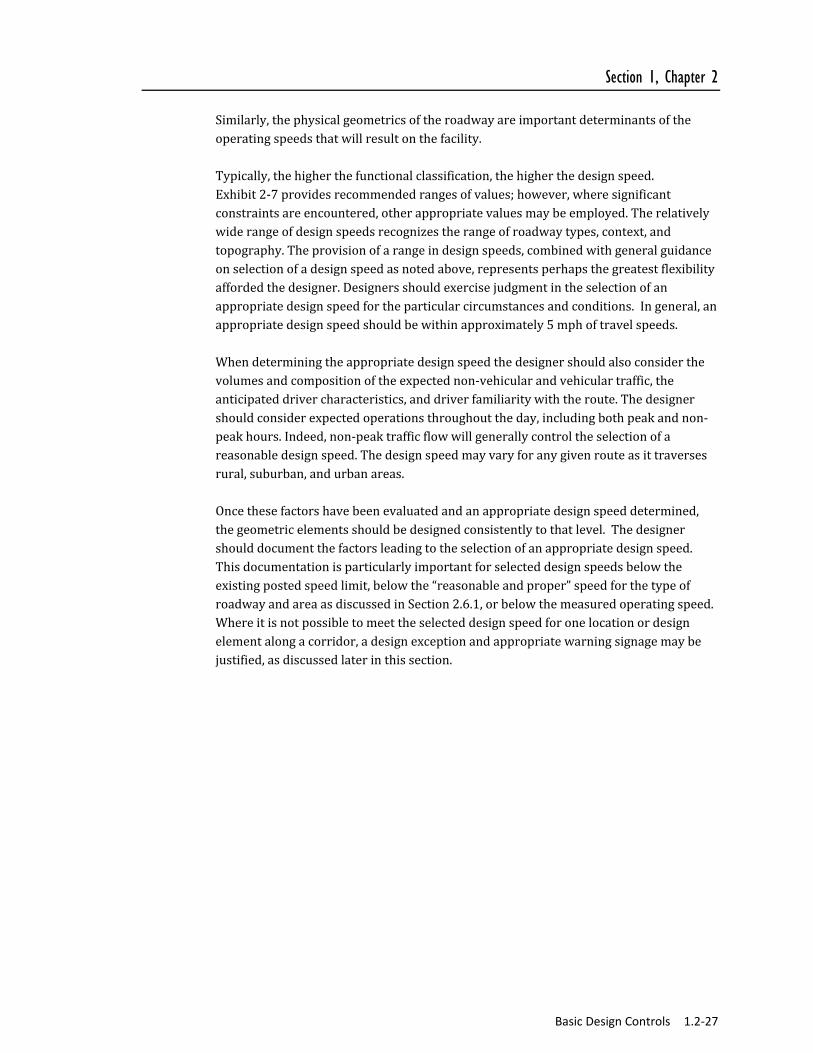
Similarly,thephysicalgeometricsoftheroadwayareimportantdeterminantsoftheoperatingspeedsthatwillresultonthefacility.Typically,thehigherthefunctionalclassification,thehigherthedesignspeed.Exhibit2‐7providesrecommendedrangesofvalues;however,wheresignificantconstraintsareencountered,otherappropriatevaluesmaybeemployed.Therelativelywiderangeofdesignspeedsrecognizestherangeofroadwaytypes,context,andtopography.Theprovisionofarangeindesignspeeds,combinedwithgeneralguidanceonselectionofadesignspeedasnotedabove,representsperhapsthegreatestflexibilityaffordedthedesigner.Designersshouldexercisejudgmentintheselectionofanappropriatedesignspeedfortheparticularcircumstancesandconditions.Ingeneral,anappropriatedesignspeedshouldbewithinapproximately5mphoftravelspeeds.Whendeterminingtheappropriatedesignspeedthedesignershouldalsoconsiderthevolumesandcompositionoftheexpectednon‐vehicularandvehiculartraffic,theanticipateddrivercharacteristics,anddriverfamiliaritywiththeroute.Thedesignershouldconsiderexpectedoperationsthroughouttheday,includingbothpeakandnon‐peakhours.Indeed,non‐peaktrafficflowwillgenerallycontroltheselectionofareasonabledesignspeed.Thedesignspeedmayvaryforanygivenrouteasittraversesrural,suburban,andurbanareas.Oncethesefactorshavebeenevaluatedandanappropriatedesignspeeddetermined,thegeometricelementsshouldbedesignedconsistentlytothatlevel.Thedesignershoulddocumentthefactorsleadingtotheselectionofanappropriatedesignspeed.Thisdocumentationisparticularlyimportantforselecteddesignspeedsbelowtheexistingpostedspeedlimit,belowthe“reasonableandproper”speedforthetypeofroadwayandareaasdiscussedinSection2.6.1,orbelowthemeasuredoperatingspeed.Whereitisnotpossibletomeettheselecteddesignspeedforonelocationordesignelementalongacorridor,adesignexceptionandappropriatewarningsignagemaybejustified,asdiscussedlaterinthissection.

1.2‐28 Basic Design Controls
Exhibit 2‐7 Design Speed Ranges (Miles per Hour)
Roadway Type
Arterials Collectors Local
Area Type Freeway Major* Minor Major Minor Roads
Rural Natural 50 to 75 40 to 60* 35 to 60 30 to 60 30 to 55 20 to 45
Rural Developed 50 to 75 40 to 60* 35 to 60 30 to 60 30 to 55 20 to 45
Rural Village N/A 30 to 45 30 to 40 25 to 40 25 to 35 20 to 35
Suburban Low Intensity Development 50 to 75 30 to 60* 30 to 55 30 to 55 30 to 55 20 to 45
Suburban High Intensity Development 50 to 75 30 to 50* 30 to 50 25 to 50 25 to 40 20 to 40
Suburban Town Center N/A 25 to 40 25 to 40 25 to 40 25 to 35 20 to 35
Urban 50 to 75 25 to 50 25 to 40 25 to 40 25 to 35 20 to 35 N/A Not Applicable * A higher design speed may be appropriate for arterials with full access control Source: Adapted from A Policy on Geometric Design of Highways and Streets, AASHTO, 2011 – Chapter 3, Elements of Design
Higherdesignspeedsimposegreaterchallengesandconstraintsondesigners.Designersfacedwithdifficultorconstrainedconditionsmayconsiderselectingalowerdesignspeedforanelementorportionofthehighway.Thispracticecancauseproblemsinthatalargenumberofdriversmaynot“behave”asthedesignerdesiresorintendsthemto.Designsbasedonartificiallylowspeedscanresultininappropriategeometricfeaturesthatviolatedriverexpectationsanddegradethesafetyofthehighway.Theemphasisshouldbeontheconsistencyofdesignsoasnottosurprisethemotoristwithunexpectedfeatures.Therefore,thedesignspeedshouldonlybebasedonthespeedlimitifthespeedlimitisconsistentwithexistingoperatingspeedsorphysicalconstraintsofthebuiltenvironment.Designersshouldnotproposeanalternativedesignspeedforahighwayorsegmentofaprojectasadesignexception.Aseriousfundamentalproblemwithacceptingorallowingadesignexceptionfordesignspeedisbasedonitsimportancerelativetoallfeaturesofthehighway.Areductioninthedesignspeedmaybeunlikelytoaffectoveralloperatingspeeds.Itwillpotentiallyresultintheunnecessaryreductionofallofthespeed‐relateddesigncriteriaratherthanjusttheoneortwofeaturesthatledtotheneedfortheexception.Theacceptablealternativeapproachtoadesignspeedexceptionistoevaluateeachgeometricfeatureindividually,addressingexceptionsforeachfeaturewithinthecontextoftheappropriatedesignspeed.Occasionally,projectsretaingeometricelements,suchastightcurves,superelevation,orrestrictedsightdistancesthataredesignedforaspeedlowerthanthedesignspeedforthecorridor.Thismaybeduetoadjacentlanduse,ortoenvironmentalorhistoricconstraints.Inthesecases,thedesignershouldrecommendapostedspeedconsistentwiththegeometricfeatures.Whereitisdesirabletomaintainahigherconsistentspeed

Section 1, Chapter 2
Basic Design Controls 1.2‐29
throughoutacorridor,thedesignershouldinstallappropriatecautionarysigningatlocationswithdesignelementsthatdonotmeetthecriteriaforthepostedspeed.
2.6.5 Design Speed and Traffic Calming
Thetermtraffic‐calmingreferstoavarietyofphysicalmeasurestoreducevehicularspeedsprimarilyinresidentialneighborhoods.Theloweringofoperatingspeedsisoftentheappropriatesolutiontoaddressingsafetyproblems.Suchproblemstypicallyinvolvevehicleconflictswithpedestrians,bicyclists,andschoolchildren.Researchhasshownthatmeasurablereductionsinoperatingspeedsarepossiblethroughtraffic‐calming.Alocalroadorstreet,andinsomeinstancesotherroadwaysthatfunctionasalocalroadorstreet,mayhaveanexistingoperatingspeedfarinexcessofthespeedlimitorthetargetspeed.Inthesecasesitmaybeacceptable,andconsistentwithgoodengineeringpractice,todevelopadesignthatwilllowertheoperatingspeed.Generally,thedesignspeedselectedfortrafficcalmingelementsshouldbeconsistentwiththetargetspeedforthecorridorasawhole.Thetrafficcalmingelementsshouldnotresultinoperatingspeedssubstantiallylowerthanthetargetspeedatcertainpointsalongthecorridorandhigherspeedselsewhere.Selectionofareasonabledesignspeedfortrafficcalmingelements,selectionoftypeofelements,andthespacingoftrafficcalmingelementscanhelpachievethedesireduniformreductioninoperatingspeedalongaroadway.Greatcaremustbeexercisedtoensurethattheproposeddesignwillactuallyreducetheoperatingspeedstolevelsconsistentwiththedesign.Theburdenisontheindividualdesignerofatraffic‐calmingfeaturetodocumentareasonableexpectationthattheproposedmeasureswillreducetheoperatingspeed.Oncetrafficcalminghasbeenimplemented,monitoringoftheperformanceoftheprojectshouldbeundertakentoassurethatspeedshaveindeedbeenreduced,andtoprovidevaluablelessonsforfuturetraffic‐calmingprojects.Chapter1‐6andChapter2‐3providesmoredetailontoolsandtechniquesfortrafficcalming.
2.6.6 High Speeds and Safety for Pedestrian and Bicyclists
Ineverycase,thedesignershouldseektomaintainorimprovesafetyforallusergroups.Safetyisoftenmeasuredbothintermsofthelikelihoodofacrashandtheexpectedseverityofacrash.Asmotorvehiclespeedsincrease,theseverityofcrashesbetweenmotorvehiclesandbicyclesorpedestriansincreases.Inthehighspeedenvironment,safetyforpedestriansandbicyclistscanbeenhancedbyreducingtheexposureofbicyclistsandpedestrianstomotorvehicletraffic,therebyreducingthelikelihoodofcrashes.Alongroadwaysegments,greaterseparationofmotorvehicleandnon‐motorizeduserscanbeprovidedbyincludingshoulders,bicyclelanes,orbufferedsidewalks.Atcrossings,theexposureofbicyclistsandpedestrianstohighspeedmotorvehicletraffic

1.2‐30 Basic Design Controls
canbemitigatedthroughsignal‐controlledcrossings,gradeseparation,andinstallationofcrossingislandsormedians.
2.6.7 Selecting Bicycle Design Speed
Bicycledesignspeedisalsoanimportantconsideration.Inmostcases,thedesignspeedforbicyclesisnomorethan20mph;thus,foron‐roadtravel,thedesignspeedchosenformotorvehiclesappropriatelyaccommodatesbicycles.Sharedusepathsshouldbedesignedforaselectedspeedthatisatleastashighasthepreferredspeedofthefasterbicyclists.Currentpracticesuggestsadesignspeedof20mphforbicyclists.(Althoughbicyclistscantravelfasterthanthis,todosowouldbeinappropriateforthistypeofsharedusesetting.)Designandtrafficcontrolscanbeusedtodeterexcessivespeedandencouragefasterbicycliststousetheroadwaysystem;however,lowerdesignspeedsshouldnotbeselectedtoartificiallyloweruserspeeds.Whenadowngradeexceedsfourpercent,orwherestrongprevailingtailwindsexist,adesignspeedof30mphisadvisable.Downgradesinexcessofsixpercentshouldbeavoidedonsharedusepaths.Onunpavedpaths,wherebicycliststendtoridemoreslowly,lowerdesignspeedsof15mphformostconditions,and20mphwheretherearegrades,areappropriate.Itshouldbenotedthatbicycledesignspeedisusuallyonlyafactorwhenconsideringthedesignofoff‐roadfacilities.
2.6.8 Selecting Pedestrian Design Speed
Muchlikeotherroadwayusers,thespeedatwhichpeoplewalkvariesconsiderably;however,walkingspeedusuallydoesnothaveasubstantialinfluenceonthegeometricdesignofroadways.Acriticalexceptiontothisisthepedestrian’sinfluenceonthedesignofintersectionsandcrosswalks,andthetimingoftrafficsignals.ThechoiceofwalkingspeedforintersectionsandtrafficsignaldesignisdiscussedintheManualonUniformTrafficControlDevices(MUTCD).
2.7 Sight Distance
Sightdistanceisthelengthofroadwayaheadthatisvisibletotheroadwayuser.Inmostcases,specificsightdistancemeasuresapplytomotorvehiclesandbicyclists.Thefourfollowingaspectsarecommonlydiscussedformotorvehiclesightdistance: Stoppingsightdistance, Passingsightdistance, Decisionsightdistance,and Intersectionsightdistance.

Section 1, Chapter 2
Basic Design Controls 1.2‐31
Allofthesesightdistancesarerelatedtothedesignspeedoftheroadway.ThedesignershouldrefertoAASHTO’sAPolicyonGeometricDesignofHighwaysandStreetsfordetailedinformationfortheuseandcalculationofsightdistances.
2.7.1 Stopping Sight Distance
Theprovisionofadequatestoppingsightdistance(SSD)isacriticalsightdistanceconsiderationfordesignandisdescribedinmoredetailbelow.
2.7.1.1 Motor Vehicle Stopping Sight Distance
Stoppingsightdistanceisthedistancenecessaryforavehicletravelingatthedesignspeedtostopbeforereachingastationaryobjectinitspath.Thesightdistanceateverypointalongaroadwayshouldbeatleastthestoppingsightdistance.Exhibit2‐8providesstoppingsightdistancesforarangeofdesignspeedsandgrades.
2.7.1.2 Bicycle Stopping Sight Distance
Foron‐roadtravel,thestoppingsightdistanceformotorvehiclesappropriatelyaccommodatesbicycles.However,bicyclestoppingsightdistanceisanimportantconsiderationinthedesignofoff‐roadfacilitiessuchassharedusepaths.
2.7.1.3 Sight Distance for Pedestrians
Thereisnotaparallel“stoppingsightdistance”considerationforpedestrianssincetheyusuallytravelatlowerspeedsandcanstopwithinafewfeet.However,thedesignermustconsidertheimportanceofpedestrians’abilitytoviewandreacttopotentialconflicts.Thedesignershouldprovideadequatesightlinesatstreetcrossings,aroundcorners,andatotherlocationswherepedestriansinterfacewithotherusers.Forexample,atstreetcrossinglocations,pedestriansshouldbeabletoseeasufficientportionofthetrafficstreamtojudgethesuitabilityofgapsforcrossingthestreet.

1.2‐32 Basic Design Controls
Exhibit 2‐8 Motor Vehicle Stopping Sight Distances
Design Speed
Stopping Sight Distance (ft) by Percent Grade (%)
Downgrade Upgrade 0 3 6 9 3 6 9
20 115 116 120 126 109 107 104 25 155 158 165 173 147 143 140 30 200 205 215 227 200 184 179 35 250 257 271 287 237 229 222 40 305 315 333 354 289 278 269 45 360 378 400 427 344 331 320 50 425 446 474 507 405 388 375 55 495 520 553 593 469 450 433 60 570 598 638 686 538 515 495 65 645 682 728 785 612 584 561 70 730 771 825 891 690 658 631 75 820 866 927 1003 772 736 704
Source: A Policy on Geometric Design of Streets and Highways, AASHTO, Washington DC, 2011. Chapter 3 Elements of Design Table 3-2
2.7.2 Passing Sight Distance
Fortwo‐lanehighways,passingmaneuversinwhichfastervehiclesmoveaheadofslowervehiclesmustbeaccomplishedonlanesregularlyusedbyopposingtraffic.Ifpassingistobeaccomplishedsafely,passingsightdistanceisnecessarytoallowthepassingdrivertoseeasufficientdistanceahead,clearoftraffic,tocompletethepassingmaneuverwithoutcuttingoffthepassedvehicleandbeforemeetinganopposingvehiclethatappearsduringthemaneuver.TheAASHTO’sAPolicyonGeometricDesignofHighwaysandStreetsincludesdetailedinformationfortheuseandcalculationofpassingsightdistances.
2.7.3 Decision Sight Distance
Decisionsightdistanceaddsadimensionoftimetostoppingsightdistancetoallowadrivertodetectandreacttoanunexpectedconditionalongaroadway.Decisionsightdistanceissuggestedwhenthereisevidencethatitwouldbeprudenttoprovidelongersightdistance,suchaswhencomplexdecisionsareneededorwheninformationisdifficulttoperceive.Itisthedistanceneededforadrivertodetectanunexpectedorotherwisedifficult‐to‐perceiveinformationsourceorconditioninaroadwayenvironmentthatmaybevisuallycluttered,recognizetheconditionoritspotentialthreat,selectanappropriatespeedandpath,andinitiateandcompletethemaneuversafelyandefficiently.Exhibit2‐9providesdecisionsightdistancesforarangeofdesignspeeds.
Section 1, Chapter 2
Basic Design Controls 1.2‐33
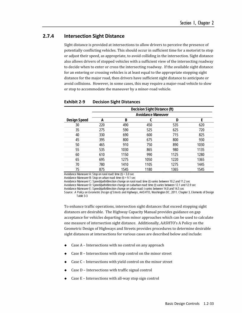
2.7.4 Intersection Sight Distance
Sightdistanceisprovidedatintersectionstoallowdriverstoperceivethepresenceofpotentiallyconflictingvehicles.Thisshouldoccurinsufficienttimeforamotoristtostoporadjusttheirspeed,asappropriate,toavoidcollidingintheintersection.Sightdistancealsoallowsdriversofstoppedvehicleswithasufficientviewoftheintersectingroadwaytodecidewhentoenterorcrosstheintersectingroadway.Iftheavailablesightdistanceforanenteringorcrossingvehiclesisatleastequaltotheappropriatestoppingsightdistanceforthemajorroad,thendrivershavesufficientsightdistancetoanticipateoravoidcollisions.However,insomecases,thismayrequireamajor‐roadvehicletosloworstoptoaccommodatethemaneuverbyaminor‐roadvehicle.
Exhibit 2‐9 Decision Sight Distances
Decision Sight Distance (ft) Avoidance Maneuver
Design Speed A B C D E 30 220 490 450 535 620 35 275 590 525 625 720 40 330 690 600 715 825 45 395 800 675 800 930 50 465 910 750 890 1030 55 535 1030 865 980 1135 60 610 1150 990 1125 1280 65 695 1275 1050 1220 1365 70 780 1410 1105 1275 1445 75 875 1545 1180 1365 1545
Avoidance Maneuver A: Stop on rural road: time (t) = 3.0 sec Avoidance Maneuver B: Stop on urban road: time (t) = 9.1 sec Avoidance Maneuver C: Speed/path/direction change on rural road: time (t) varies between 10.2 and 11.2 sec Avoidance Maneuver D: Speed/path/direction change on suburban road: time (t) varies between 12.1 and 12.9 sec Avoidance Maneuver E: Speed/path/direction change on urban road: t varies between 14.0 and 14.5 sec Source: A Policy on Geometric Design of Streets and Highways, AASHTO, Washington DC, 2011. Chapter 3, Elements of Design
Table 3-3
Toenhancetrafficoperations,intersectionsightdistancesthatexceedstoppingsightdistancesaredesirable.TheHighwayCapacityManualprovidesguidanceongapacceptanceforvehiclesdepartingfromminorapproacheswhichcanbeusedtocalculateonemeasureofintersectionsightdistance.Additionally,AASHTO’sAPolicyontheGeometricDesignofHighwaysandStreetsprovidesprocedurestodeterminedesirablesightdistancesatintersectionsforvariouscasesaredescribedbelowandinclude: CaseA–Intersectionswithnocontrolonanyapproach
CaseB–Intersectionswithstopcontrolontheminorstreet
CaseC–Intersectionswithyieldcontrolontheminorstreet
CaseD–Intersectionswithtrafficsignalcontrol
CaseE–Intersectionswithall‐waystopsigncontrol
1.2‐34 Basic Design Controls
CaseF–Leftturnsfromthemajorroad
2.7.4.1 Intersection Sight Triangle
Clearsighttrianglesarethoseareasalongtheintersectionapproachlegsthatshouldbeclearofobstructionsthatcanblockroaduser’sviewofoncomingtraffic.Thedimensionsofthetrianglearebasedonthedesignspeedoftheintersectingroadwaysandthetypeoftrafficcontrolusedattheintersection,gradesontheroadways,andtheroadwaywidth.Twotypesofclearsighttrianglesareusedateachintersection:approachsighttrianglesanddeparturesighttriangles.Approachsighttrianglesareapplicableforwhentheminorroaddriverisinmotionwhiledeparturesighttrianglesapplywhentheminorroadvehicleisacceleratingfromastopposition.
2.7.4.2 Identification of Sight Obstructions within Sight Triangles
Withinasighttriangletherearemanyobstructionsthatcanobscurethedriver’sviewofoncomingvehicles.Thesemayincludebuildings,vegetation,longitudinalbarriersorretainingwalls,sideslopes,etc.Thehorizontalandverticalalignmentoftheintersectingroadwaysandanyvisualobstructionsshouldbeconsidered.Fordesignpurposes,thedriver’seyeisassumedtobe3.5feetabovetheroadway.Theobjectthatisusedfordesignapproximatestheheightofanautomobileandisassumedtobe3.5feetabovetheroadway.Wherethesightdistancevalueusedindesignisbasedonasingle‐unitorcombinationtruckasthedesignvehicle,itisalsoappropriatetousetheeyeheightofatruckdriverincheckingsightobstructions.Therecommendedvalueofatruckdriver’seyeheightis7.6feetabovetheroadwaysurface.
2.7.4.3 Case A – Intersections with No Control on Any Approach
Whereintersectionmovementsarenotcontrolledbyatrafficcontroldevice(i.e.,signal,STOPorYIELDsign),driversapproachingtheintersectionfromanydirectionmustbeabletoseepotentiallyconflictingvehiclesinsufficienttimetostopbeforereachingtheintersection.Theintersectionsighttriangle,asillustratedinExhibit2‐10isformedbythesightdistancealongtheminorstreet(indicatedasDistanceA)andtheintersectionsightdistancealongthemajorstreet(indicatedasDistanceB).Thecorrespondingdistances,arrayedbydesignspeedarebasedonthedistancetraveledastheapproachingdriverperceivesandreactstothepresenceofapossiblyconflictingvehicle,andbringstheirownvehicletoastop.Forexample,basedonthevaluesExhibit2‐10,anintersectionofamajorstreetwithadesignspeedof40milesperhourwithaminorstreetwithadesignspeedof25milesperhourwouldrequireasightdistancedefinedbyanintersectionsightdistanceof195feet(majorstreet)and115feet(minorstreet).Iftheminorstreetwasona6percentgradethentheintersectionsightdistancewouldbe127feet(115feetmultipliedbythe1.1gradeadjustmentfactor)forthedowngradeand104feetfortheupgrade.

Section 1, Chapter 2
Basic Design Controls 1.2‐35
Exhibit 2‐10 Sight Triangle Case A
Approach Sight Triangles
Design Speed (mph)
Sight Triangle Legs: Case A – No Traffic Control Length of Legs, both major and minor streets, A and B
(feet)
15 70 20 90 25 115 30 140 35 165 40 195 45 220 50 245 55 285 60 325 65 365 70 405 75 445
For approach grades greater than 3 percent, apply factors below.
Approach Grade %
Approach Grade Adjustments to Sight Distance Design Speed (mph)
15 20 25 30 35 40 45 50 55 60 65+ -6 -5 -4
-3 to +3 +4 +5 +6
1.1 1.0 1.0 1.0 1.0 1.0 1.0
1.1 1.0 1.0 1.0 1.0 1.0 1.0
1.1 1.1 1.0 1.0 1.0 1.0 0.9
1.1 1.1 1.1 1.0 1.0 0.9 0.9
1.1 1.1 1.1 1.0 0.9 0.9 0.9
1.1 1.1 1.1 1.0 0.9 0.9 0.9
1.1 1.1 1.1 1.0 0.9 0.9 0.9
1.2 1.1 1.1 1.0 0.9 0.9 0.9
1.2 1.1 1.1 1.0 0.9 0.9 0.9
1.2 1.1 1.1 1.0 0.9 0.9 0.9
1.2 1.2 1.1 1.0 0.9 0.9 0.9
Source: A Policy on Geometric Design of Streets and Highways, AASHTO, Washington DC, 2011. Chapter 9 Intersections

1.2‐36 Basic Design Controls
2.7.4.4 Case B – Stop Control on Minor Street
Atanintersectionwithstopcontrolontheminorstreet,asillustratedinExhibit3‐11,thestoppedminor‐streetdrivermustbeabletoseemotorvehiclesandbicyclesapproachingonthemajorstreetfromeitherdirection,atsufficientdistancetoallowcrossingorturningmaneuversfromtheminorstreet.Thelegoftheintersectionsighttriangleontheminorstreet(DimensionA)isthedistancebetweenthedriver’seyeandfrontofvehicle(8feet)plusdistancefromfrontofvehicletoedgeofpavement(6.5feet,prefer10feet)plusthedistancefromedgeofpavementtomiddleoflaneofinterest(e.g.,6feetforarightturn,18feetforaleftturnonanundivided2lanehighway,etc.)Themajorstreetlegofthetriangleistheintersectionsightdistancealongthemajorroad(DimensionB).
Left Turns from Stop Controlled Minor Street
Formotorvehiclesmakingaleftturn,theintersectionsightdistancealongthemajorstreet(DimensionB)isgivenforanintersectionof2lanestreetsinExhibit3‐11.Forexample,atadesignspeedof35milesperhouronthemajorstreet,andwiththeminorstreetdriver’seyeat14.5feetfromtheedgeofthemajorstreettravellane,theintersectionsightdistance(DimensionB)is390feet.Itisrecommendedthatthisintersectionsightdistance(DimensionB)beappliedalongthemajorstreetinbothdirectionsfromtheintersection.
Right Turns from Stop Controlled Minor Street
Formotorvehiclesmakingarightturnfromtheminorstreet,theintersectionsightdistancesaregiveninExhibit2‐11.
Through Movement from Stop Controlled Minor Street
Formotorvehiclescrossingthemajorstreetfromastop‐controlledminorstreet,theintersectionsightdistancesaregiveninExhibit2‐11.

Section 1, Chapter 2
Basic Design Controls 1.2‐37
Exhibit 2‐11 Sight Triangle Case B
Departure Sight Triangles
Sight Triangle Legs: Case B – Stop Control on Cross Street
Major Street Design Speed (mph)
Length of Sight Triangle Legs (feet)
Minor Street for Vehicles Approaching from Right (AR, feet)
Minor Street for Vehicles Approaching
from Left (AL, feet)
Major Street for Left Turns
(B, feet)
Major Street for Right Turns or
Through (B, feet)
15 20 25 30 35 40 45 50 55 60 65 70 75
32.5 32.5 32.5 32.5 32.5 32.5 32.5 32.5 32.5 32.5 32.5 32.5 32.5
20.5 20.5 20.5 20.5 20.5 20.5 20.5 20.5 20.5 20.5 20.5 20.5 20.5
170 225 280 335 390 445 500 555 610 665 720 775 830
145 195 240 290 335 385 430 480 530 575 625 670 720
Sight triangle legs shown are for passenger car crossing or turning into a two-lane street, with grades (all approaches) 3 percent or less. For other grades and for other major street widths, recalculate using AASHTO Green Book formulas. Source: A Policy on Geometric Design of Streets and Highways, AASHTO, Washington DC, 2011. Chapter 9 Intersections

1.2‐38 Basic Design Controls
2.7.4.5 Case C – Yield Control
Atintersectionswithyieldcontrolontheminorstreet,theminorstreetdriverarepermittedtoenterorcrossthemajorroadwithoutstopping,iftherearenopotentiallyconflictingvehicles.Yield‐controlledapproachesgenerallyneedgreatersightdistancethanstop‐controlledapproaches.Forfour‐legintersectionswithyieldcontrolontheminorroad,twoseparatepairsofapproachsighttrianglesshouldbeprovided–onesettoaccommodatecrossingthemajorroadandtheothertoaccommodateleftandrightturns.Bothsetsofsighttrianglesshouldbecheckedforpotentialsightobstructions.Forthree‐legintersectionswithyieldcontrolontheminorroad,onlythesighttrianglestoaccommodateleftandrightturnsneedtobechecked.ThemajorandminorstreetlegsofthesighttriangleareshowninExhibit2‐12.

Section 1, Chapter 2
Basic Design Controls 1.2‐39
Exhibit 3‐12 Sight Triangle — Case C
Sight Triangle — Case C: Yield Control on Cross Street
Design Speed (Major Street, mph)
Crossing without Stopping Sight Triangle Legsa
(feet)
Left and Right Turn without Stopping Sight Triangle Legsa
(feet) Minor Street
(A, feet) Major Streetb
(B, feet) Minor Street
(A, feet) Major Street
(B, feet) 15 20 25 30 35 40 45 50 55 60 65 70 75
80 115 155 200 250 305 360 425 495 570 645 730 720
145 195 240 290 335 385 430 480 530 575 625 670 720
80 115 155 200 250 305 360 425 495 570 645 730 720
180 240 295 355 415 475 530 590 650 710 765 825 885
a Sight triangle legs shown are for passenger car crossing or turning into a two-lane street, with grades (all approaches) 3 percent or less. For other grades and major street widths, recalculate length of legs from AASHTO Green Book formulas.
b Lengths are for design speeds of 20 to 50 mph on minor road. For other minor road design speeds, recalculate length of legs from AASHTO Green Book formulas.
Source: A Policy on Geometric Design of Streets and Highways, AASHTO, Washington DC, 2011. Chapter 9 Intersections

1.2‐40 Basic Design Controls
Case C – Yield Control at Roundabouts
Atroundabouts,thelocationneedingevaluationofintersectionsightdistanceisattheentries.Theentrysightdistanceevaluationusestwoconflictingapproaches:enteringstream(i.e.,thosevehiclesenteringfromtheimmediateupstreamentry)andcirculatingstream(i.e.,thosevehiclesonthecircularroadway).ThelengthoftheconflictinglegisshowninExhibit3‐13forarangeofconflictingapproachspeeds.Thesightdistancelegsforroundaboutsfollowthecurvatureoftheroadway,thereforedistancesshouldbemeasurednotasstraightlinesbutasdistancesalongthevehicularpath.TheFHWARoundaboutGuiderecommendslimitingthelengthoftheapproachlegofthesighttriangleto49feet.
Exhibit 3‐13 Roundabout Intersection Sight Distance: Computed Length of Conflicting Leg
Conflicting Approach Speed (mph)
Computed Distance (ft)
10 15 20 25 30
95.4 143.0 190.1 238.6 286.3
Source: Roundabouts: An Informational Guide, FHWA, Washington DC, 2010.
2.7.4.6 Case D – Intersections with Traffic Signal Control
Atsignalizedintersections,thefirstvehiclestoppedononeapproachshouldbevisibletothedriverofthefirstvehiclestoppedoneachoftheotherapproaches.Whererightturnsonredarepermitted,thesightdistancetriangleforarightturnfromstopapplies(CaseB).Leftturningmotorvehiclesandbicyclesshouldhavesufficientsightdistance,intotheopposingroadway,tobeabletoselectgapssufficienttomaketheirleft‐turnmovement(CaseB).Wherethisdistanceisinsufficient,mostlikelyduetoverticalorhorizontalcurvature,theremediescanincludeconfiningtheleftturntoaprotectedsignalphase,orprohibitingtheleftturn.A“NoTurnonRed”(NTOR)signmayalsobenecessaryifthesightlinetotheleftisnotsufficientasindicatedinCaseB.Further,itmaybenecessarytoremovetheprogrammedflashingoperationofthetrafficsignal.
2.7.4.7 Case E – Intersections with All‐Way Stop Control
Atintersectionswithall‐waystopcontrol,thefirststoppedvehicleononeapproachshouldbevisibletothedriversofthefirststoppedvehiclesoneachoftheotherapproaches.Forthisreason,all‐waystopcontrolmaybeapreferableoptionatintersectionswhere,duetotopographicorman‐madeconstraints,sightdistancesforothertypesofcontrolcannotbeobtained.

Section 1, Chapter 2
Basic Design Controls 1.2‐41
2.7.4.8 Case F – Left Turns from the Major Road
Driversturningleftacrossoncomingtrafficofamajorroadwayrequiresufficientsightdistancetodeterminewhenthereistimetocompletethemaneuver.IfstoppingsightdistancehasbeenprovidedcontinuouslyalongthemajorroadandifsightdistanceforCaseB(stopcontrol)orCaseC(yieldcontrol)hasbeenprovidedforeachminor‐roadapproach,sightdistancewillgenerallybeadequateforleftturnsfromthemajorroads.Therefore,noseparatecheckofsightdistanceforCaseFmaybeneeded.However,atthree‐legintersectionsordrivewayslocatedonornearahorizontalcurveorcrestverticalcurveonthemajorroad,theavailabilityofadequatesightdistanceforleftturnsfromthemajorroadshouldbechecked.Inaddition,theavailabilityofsightdistancefromdividedhighwaysshouldbecheckedbecauseofthepossibilityofsightobstructionsinthemedian.IntersectionsightdistancesforCaseFislistedinExhibit2‐14.
Exhibit 3‐14 Case F Intersection Sight Distance
Design Speed (mph)
Sight Triangle Leg (feet)
15 20 25 30 35 40 45 50 55 60 65 70 75 80
125 165 205 245 285 325 365 405 445 490 530 570 610 650
Intersection sight distances shown are for passenger car making a left turn from an undivided highway. For other conditions and design vehicles, recalculate length of legs using AASHTO Green Book formulas. Source: A Policy on Geometric Design of Streets and Highways, AASHTO, Washington DC, 2011. Chapter 9 Intersections

1.2‐42 Basic Design Controls
2.8 For Further Information:
APolicyonGeometricDesignofHighwaysandStreets,6thEdition,AASHTO,2011.
GuidefortheDevelopmentofBicycleFacilities,AASHTO,2012
UrbanBikewayDesignGuide,NACTO,2011.
GuideforthePlanning,Design,andOperationofPedestrianFacilities,AASHTO,2004
AGuidetoAchievingFlexibilityinHighwayDesign,AASHTO,2004.
HighwayCapacityManual,TransportationResearchBoard,2010.
ManualonUniformTrafficControlDevices,FederalHighwayAdministration,2009.
Real‐TimeHumanPerceptions:TowardaBicycleLevelofService,Landis,Bruce,TransportationResearchRecord1578,WashingtonDC,TransportationResearchBoard,1997.
DevelopmentoftheBicycleCompatibilityIndex:ALevelofServiceConcept,FinalReport,FHWA‐RD‐98‐072,1998.
DevelopmentoftheBicycleCompatibilityIndex:ALevelofServiceConcept,ImplementationManual,FHWA‐RD‐98‐095,1998.
TransitCapacityandQualityofServiceManual,TransportationResearchBoard,TransitCooperativeResearchProgram.Report100,2ndEdition,2003.
TRBSpecialReport254ManagingSpeed:ReviewofCurrentPracticesforSettingandEnforcingSpeedLimits,TransportationResearchBoard,WashingtonDC,1998.
FlexibilityinHighwayDesign,FederalHighwayAdministration,Washington,DC.
AGuidetoBestPracticesinContextSensitiveSolutions,TransportationResearchBoard,NationalCooperativeHighwayResearchProgram.Report480.WashingtonDC,2002.
ADAAGManual:AGuidetotheAmericanswithDisabilitiesActAccessibilityGuidelines,TheU.S.ArchitecturalandTransportationBarriersComplianceBoard(TheAccessBoard).Washington,DC,2002.
StandardsandAnthropometryforWheeledMobility,TheU.S.ArchitecturalandTransportationBarriersComplianceBoard(TheAccessBoard).Washington,DC,2005.

![[eBook] Java Basic Swing Gui Controls](https://static.fdocuments.in/doc/165x107/577d26751a28ab4e1ea146e2/ebook-java-basic-swing-gui-controls.jpg)