Basic Data Report for Well Plugging and Abandonment ... · Basic Data Report for Well Plugging and...
32
DOE/WIPP-08-3326 Basic Data Report for Well Plugging and Abandonment, Reconfiguration, and New Well Drilling Activities for Fiscal Year 2008 U.S. Department of Energy February 2009
Transcript of Basic Data Report for Well Plugging and Abandonment ... · Basic Data Report for Well Plugging and...
DOE/WIPP-08-3326 Basic Data Report for Well Plugging and Abandonment,
Reconfiguration, and New Well Drilling Activities for Fiscal Year 2008
U.S. Department of Energy
February 2009

Basic Data Report for Well Plugging and Abandonment, Reconfiguration, and New Well Drilling Activities for Fiscal Year 2008 DOE/WIPP-08-3326
2
This document has been submitted as required to:
Office of Scientific and Technical Information P.O. Box 62
Oak Ridge, TN 37831 (865) 576-8401
Additional information about this document may be obtained by contacting the WIPP Information Center at (800) 336-9477. Copies may be obtained by contacting the
National Technical Information Service, U.S. Department of Commerce, 5285 Port Royal Road, Springfield, VA 22101.
This document was prepared for the U.S. Department of Energy By Washington TRU Solutions LLC
Under Contract No. DE-AC29-01AL66444.

Basic Data Report for Well Plugging and Abandonment, Reconfiguration, and New Well Drilling Activities for Fiscal Year 2008 DOE/WIPP-08-3326
3
TABLE OF CONTENTS
1.0 INTRODUCTION.................................................................................................. 5
2.0 PROGRAM METHODOLOGY.............................................................................. 5
3.0 PLUGGING AND ABANDONMENT ..................................................................... 6
3.1 Well WIPP-30 ............................................................................................ 7 3.2 Well H-6b ................................................................................................. 10
4.0 MONITORING WELL RECONFIGURATION...................................................... 13
4.1 Monitoring Well AEC-7............................................................................. 13 4.2 Monitoring Well H-15 ............................................................................... 17 4.3 Monitoring Well H-16 ............................................................................... 20
5.0 NEW MONITORING WELL DRILLING AND COMPLETION.............................. 23
5.1 New Monitoring Well H-15R..................................................................... 23 5.2 New Monitoring Well H-6bR..................................................................... 25
6.0 WELL DEVELOPMENT...................................................................................... 29
7.0 WASTE MANAGEMENT .................................................................................... 30
LIST OF TABLES
Table 1 - Well Development Methods ........................................................................... 29
LIST OF FIGURES Figure 1 - Construction of WIPP-30, FY 2008 P&A.................................................... 9 Figure 2 - Well Monument at WIPP-30..................................................................... 10 Figure 3 - Construction of Well H-6b, FY 2008 P&A ................................................ 12 Figure 4 - The Halliburton Logging Truck and Casing Perforating Guns on
the Trailer in the Foreground ................................................................... 14 Figure 5 - AEC-7 Reconfiguration, 2008 .................................................................. 16 Figure 6 - H-15 Reconfiguration, 2008 ..................................................................... 19 Figure 7 - Well H-16 Reconfiguration, 2008 ............................................................. 22 Figure 8 - Surface Casing at H-15R......................................................................... 23 Figure 9 - Setting 5.5-Inch Fiberglass Casing at H-15R........................................... 24 Figure 10 - New Well H-15R Construction Details ..................................................... 27 Figure 11 - New Well H-6bR Construction Details ..................................................... 28 Figure 12 - Air Lift Well Development at H-15............................................................ 30 Figure 13 - Dedicated Fresh Water Tank at the Staging Area ................................... 31 Figure 14 - Frac Tank Being Delivered to Location.................................................... 32

Basic Data Report for Well Plugging and Abandonment, Reconfiguration, and New Well Drilling Activities for Fiscal Year 2008 DOE/WIPP-08-3326
4
ABBREVIATIONS AND ACRONYMS AIS Air Intake Shaft AMSL above mean sea level BLM Bureau of Land Management bgs below ground surface cm centimeter DOE U.S. Department of Energy FY fiscal year gal gallon gm gram JHA job hazard analysis lb pound NMOSE New Mexico Office of the State Engineer OSE State Engineer's Office P&A plugging and abandonment PBTD plug back the depth PIP production injection packers PPE personal protective equipment psi pounds per square inch PVC polyvinyl chloride SNL Sandia National Laboratories STR Site Technical Representative WIPP Waste Isolation Pilot Plant WRES Washington Regulatory and Environmental Services WTS Washington TRU Solutions LLC

Basic Data Report for Well Plugging and Abandonment, Reconfiguration, and New Well Drilling Activities for Fiscal Year 2008 DOE/WIPP-08-3326
5
1.0 INTRODUCTION The Waste Isolation Pilot Plant (WIPP) is a U.S. Department of Energy (DOE) facility for disposal of transuranic mixed waste under a permit issued by the New Mexico Environment Department. WIPP is 26 miles southeast of Carlsbad, New Mexico, in eastern Eddy County. Disposal panels are mined in the Permian Salado Formation at a depth of 2,150 feet below ground surface (bgs). Field activities for this Basic Data Report were initiated in February 2008, and concluded in July 2008. The FY 2008 program included the plugging and abandonment (P&A) of two monitoring wells, which permanently removed them from the monitoring network; the reconfiguration of three existing monitoring wells; and drilling and completion of two new groundwater monitoring wells. In addition, two existing monitoring wells were bailed to restore natural formation water to the casing. This Basic Data Report presents the summary of procedures followed for each well completion as documented by the Site Technical Representative (STR) and the field geologist contracted by Washington TRU Solutions LLC (WTS). 2.0 PROGRAM METHODOLOGY The general approach to the work was the same for each well, and health and safety standards were maintained throughout the program, as described below. A Job Hazard Analysis (JHA) was submitted to the STR before the start of any work at the WIPP site. The JHA documented the commitment of participating contractors and their personnel to providing a healthy and safe work environment. The JHA included specific operations that might create a safety hazard and the preventive measures necessary to eliminate the hazard. Personnel working on the program were required to read the JHA before working. Tailgate safety meetings were held before the start of each day’s work. Job safety items were covered, such as the wearing of personal protective equipment (PPE), trip and fall hazards, falling object hazards, slip hazards, and high-pressure lines that might contain fluids or air. Whenever a change in operations occurred, additional tailgate safety meetings were held to review any new specific hazards that might arise. The WIPP facility provides highly trained 24-hour emergency and nonemergency response teams dispatched from the Central Monitoring Room. Notification procedures and emergency and nonemergency phone numbers were available throughout the program. The P&A wells and the reconfigured wells were processed by removing appurtenances, the wellhead, tubing, packers, and bridge plugs. Wells were scraped to remove oxidation scale from the casing to allow sufficient bonding between the casing and cement. After scraping, wells were circulated with clean water to remove any deleterious material from the total depth of the well. Permitting documents were submitted by Washington Regulatory and Environmental Services (WRES) and

Basic Data Report for Well Plugging and Abandonment, Reconfiguration, and New Well Drilling Activities for Fiscal Year 2008 DOE/WIPP-08-3326
6
approved by the New Mexico Office of the State Engineer (NMOSE) before work commenced on these wells. Monitoring wells DOE-2 and Cabin Baby #1 were developed by swabbing-type oilfield methods because of the depth of these completions. New well completions H-6bR and H-15R and reconfigured wells H-15, H-16, and AEC-7 were developed by bailer and airlift methods. Well development processes are included in Section 6.0 of this report. For drilling, P&A, and reconfiguration processes, a closed loop system was used for all work water and drill cuttings. Waste management handling and disposal processes are included in Section 7.0 of this report. New monitoring well completions were drilled by air rotary drilling methods and completed per WRES specifications in the zone of interest and will be included in the WIPP monitoring network. Before drilling commenced, Form wr-07, Application for Permit to Drill an Exploratory Well, was submitted by the STR and approved by NMOSE. After well completions, Form wr-20, Well Record and Drilling Log, was submitted to NMOSE by the drilling contractor. WRES managed this program, which included technical, regulatory, contractual, financial, and field oversight. The prime subcontractors for this process were RESPEC Inc. of Albuquerque, New Mexico; Stewart Brothers Drilling Co. of Milan, New Mexico; BJ Cementing Services of Hobbs, New Mexico; Halliburton Services of Hobbs, New Mexico; Reeco Swabbing Service of Hobbs, New Mexico; TFH Trucking/Frac Tank Service of Hobbs, New Mexico; Abbott Brothers Rathole Service of Hobbs, New Mexico; Weatherford Tools of Hobbs, New Mexico; Southeast Ready Mix of Carlsbad, New Mexico; Sundance Services, Inc. of Eunice, New Mexico; and Lea Land Disposal Services of Carlsbad, New Mexico. For this program, specific work varied from well to well. The following sections describe the general process of the work under the FY 2008 program. • Plugging and Abandonment – Section 3.0 • Monitoring Well Reconfiguration – Section 4.0 • New Monitoring Well Drilling and Completion – Section 5.0 Subsections concerning individual wells describe specific requirements, nuances, and problems encountered during the process. 3.0 PLUGGING AND ABANDONMENT The FY 2008 work plan outlined procedures to P&A wells H-6b and WIPP-30, permanently removing them from the monitoring network.
Basic Data Report for Well Plugging and Abandonment, Reconfiguration, and New Well Drilling Activities for Fiscal Year 2008 DOE/WIPP-08-3326
7
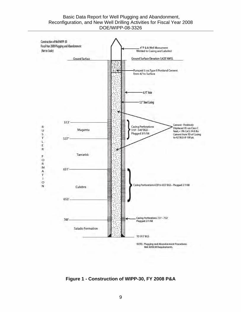
3.1 Well WIPP-30 WIPP-30 is located in Section 33, Township 21 South, Range 31 East in Eddy County, New Mexico. The well location comprises an approximately one-acre tract covered with caliche-base coarse material and surrounded by natural terrain and vegetation. The elevation at this location is 3,428 feet above mean sea level (AMSL). WIPP-30 was originally drilled to 912 feet bgs as an Upper Salado Formation test well. The well was completed with 5.5-inch steel casing to a total depth of 913 feet bgs. Baker-type production injection packers (PIP) were set at 585 feet bgs and 701 feet bgs to segregate the Salado Formation from the Culebra and Magenta Members of the Rustler Formation. The well casing was perforated in Upper Salado Formation intervals from 753 feet to 731 feet bgs, 655 feet to 629 feet bgs in the Culebra Member, and 540 feet to 510 feet bgs in the Magenta Member. The casing or this well was found to be damaged when the PIP was removed in September 2007 and got stuck inside the 5.5-inch steel casing at 50 feet bgs. Work on this well began on February 20, 2008. The driller used two 2.875-inch drill collars and one set of jars to unseat the PIP; however, attempts to unseat the PIP were unsuccessful. Attempts to clean out the casing around the outside of the packer with a wash-over tool were also unsuccessful. The PIP would not move either up or down in the casing, so the only option was to drill out the packer. The driller used a 4.5-inch tri-cone bit and two 2.875-inch drill collars and went inside the casing to the top of the PIP. At the start of drilling, the well lost circulation, indicating that a hole existed in the casing above the PIP location. A 10-sack cement mix was prepared and pumped into the casing from the top of the PIP to the surface, and the cement was allowed to set overnight. Drilling continued the next morning with good circulation from the well. Penetration rates averaged 0.5 feet per hour while drilling on the PIP. Material recovered from well circulation returns was continuously monitored at the flow nipple to confirm that the PIP was in fact being drilled out. The monitored material consistently contained stainless steel and rubber from the PIP. The packer was successfully drilled out, and P&A procedures continued. After reaming the inside of the 5.5-inch casing, the driller entered the 5.5-inch casing with 2.375-inch tubing to the total depth of well. The tubing was staged into the casing at 150-foot intervals and circulated to remove any remaining rust or scale that might have accumulated. The tubing was then used as tremmie pipe to positively displace Class C neat cement from the total depth of the well to the surface. BJ Oilfield Cementing Services was contracted to pump the calculated cement volume of 100 sacks of 15 lb/gal Class C neat cement from the total depth of the well to the surface. The cement process was staged, with Stage 1 being a 55-sack mix pumped at 100 pounds per square inch (psi) and Stage 2 being a 40-sack mix pumped at 100 psi. At the completion of Stage 1 pumping, the top of the cement was found to be at 275 feet bgs. At the completion of Stage 2 pumping, the top of the cement was found to be at 42 feet bgs. A 100 psi pump pressure was used to assure that the fracture

Basic Data Report for Well Plugging and Abandonment, Reconfiguration, and New Well Drilling Activities for Fiscal Year 2008 DOE/WIPP-08-3326
8
gradient of the Culebra and Magenta intervals was not exceeded during cement placement. Cement was monitored for proper weight throughout the process and was consistently at or above 14.8 lb/gal for Stage 1 and Stage 2. Cement was allowed to set for 4 hours. The top of the cement was measured at 42 feet bgs and the residual water level at 17 feet bgs. Water was bailed off to the top of the cement, and a five-sack Type II Portland cement mix was displaced to bring the cement to the surface. Cement quantities displaced during this process closely matched the calculated casing volume, indicating that the casing integrity was sound, casing perforations were plugged, and no formation fracturing occurred during the process. The final well disposition is depicted in Figure 1.
Basic Data Report for Well Plugging and Abandonment, Reconfiguration, and New Well Drilling Activities for Fiscal Year 2008 DOE/WIPP-08-3326
9
Figure 1 - Construction of WIPP-30, FY 2008 P&A
umstruction dWeiiWIPP·ll Fiscal Year m!Piugglng and Abandonment (~tto Scale)
513' R u Magenta s T L E R
F Tamarisk
0 R M 63 A T I
0 N Culebra
65.3'
Salado Formation
~•nt ·Positively Displaced 95 sxs Qm C Neat.< ~% CaCI, 14,8ibs Ceml?nt from TO of Casiog to42'BGS@ 100 ps.
Casing Porforations 62!7to 655' BGS - Plugge<13/ 1(08
TO 913' BGS
NOn: Pluggin!J n.nd Ah~nrlonmt~nt ·PRYQrSu.r~
Met All BI:.M RQQulrements.

Basic Data Report for Well Plugging and Abandonment, Reconfiguration, and New Well Drilling Activities for Fiscal Year 2008 DOE/WIPP-08-3326
10
An inspector from the Bureau of Land Management (BLM) was on-site throughout the cementing process. BLM approved all processes and procedures for the P&A of WIPP-30. BLM requires that permanently abandoned wells be marked with a monument. Monuments must be at least 4 inches in diameter and extend far enough above the ground surface to include the following information welded onto the steel: county, section, township, range, NMOSE number, WIPP number, and BLM right-of-way number. The monument placed on WIPP-30 well met these specifications.
Figure 2 - Well Monument at WIPP-30
3.2 Well H-6b Well H-6b (OSE File # C-2749) is located in the northwest quarter of Section 18, Township 22 south, Range 31 east, near the northwest corner of the WIPP site boundary. H-6b was drilled in 1986 by the United States Geological Survey for Sandia
Basic Data Report for Well Plugging and Abandonment, Reconfiguration, and New Well Drilling Activities for Fiscal Year 2008 DOE/WIPP-08-3326
11
National Laboratories on behalf of the U.S. Department of Energy. The purpose of this well was to fill data gaps in the stratigraphy and hydrogeology. Well H-6b was drilled to a depth of 590 feet to a diameter of 7 7/8-inches and then cased with 5-1/2-inch steel casing. The borehole was then drilled as an open-hole from 590 feet to 640 feet at a diameter of 4 3/4-inches to monitor hydraulic responses of the Culebra Member of the Rustler Formation. This well contained no PIPs or other well appurtenances so the process involved scraping the well to remove corrosion and debris from the casing and circulating the well with fresh water. After circulation, the well was plugged using a tremmie pipe placing 95.5 cubic feet of Portland Type II cement into the hole and casing. Per BLM requirement, this well was marked with a monument. The monument includes the following information welded onto the steel: county, section, township, range, NMOSE number, WIPP number, and BLM right-of-way number. Figure 3 represents the final configuration of well H-6b after P&A.

Basic Data Report for Well Plugging and Abandonment, Reconfiguration, and New Well Drilling Activities for Fiscal Year 2008 DOE/WIPP-08-3326
12
Figure 3 - Construction of Well H-6b, FY 2008 P&A
Construction ofWell H-6b After PI ugging and Abandonment
(Not to Scale)
492'
R Magenta
u 511 ' s
T L E R
Tamarisk F 0 R M A T I
604 '
0 Culebra N
627'
4' P & A Well Monument H----- Welded to Casing and Labeled
14------ 9.625 ' 00, 36 1b/ft,J-55 casing
'+--- 38' bgs
7.875' Hole
5.5' 00, 24 1blft J-55 casing
Cement (1986 installation)
Type II Portland Cement 12008P&A)
590' BGS
Open Core-Hole
T.D. 640 ' BGS

Basic Data Report for Well Plugging and Abandonment, Reconfiguration, and New Well Drilling Activities for Fiscal Year 2008 DOE/WIPP-08-3326
13
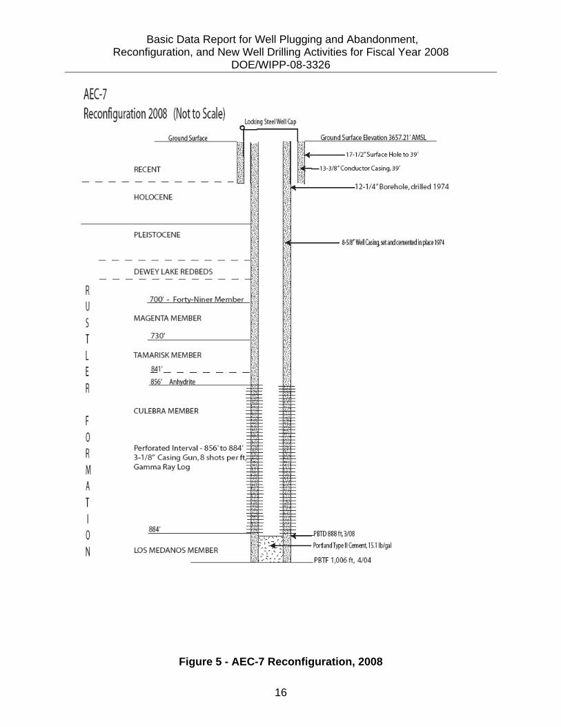
4.0 MONITORING WELL RECONFIGURATION 4.1 Monitoring Well AEC-7 The FY 2008 work plan outlined procedures to reconfigure AEC-7. The objective was to plug back the well and perforate the well casing to provide a dedicated Culebra Member monitoring well to be included in the monitoring network. AEC-7 is located in Section 31, Township 21 South, Range 32 East, in Eddy County, New Mexico. The well location comprises an approximately one-acre tract covered with caliche-base coarse material surrounded by natural terrain and vegetation. The elevation at this location is 3,656 feet AMSL. This well was drilled in 1974 by Oak Ridge National Laboratory for the U.S. Energy Research and Development Administration to evaluate the stratigraphy of geological units for the development of WIPP. The well was initially completed at 3,906 feet bgs as an open-hole monitoring well in the Anhydrite II Member of the Castile Formation with 8.625-inch steel casing set at a total depth of 1,006 feet bgs in the upper Salado Formation. Sandia National Laboratories (SNL) then deepened the well to 4,720 feet to investigate hydraulic properties of the Bell Canyon Formation in 1979 and plugged it back to 4,453 feet bgs to seal Bell Canyon bottom hole formation pressure. The well remained temporarily abandoned until 1988, when SNL plugged it back to 950 feet by setting a retrievable bridge plug and then perforating the 8.625-inch casing from 890 feet to 859 feet bgs to monitor the Culebra Member of the Rustler Formation. In 2004 the well was reconfigured by removing the bridge plug and displacing cement to 1,006 feet bgs (TD of the 8.625-inch casing). However, the Culebra perforations were found to be plugged, and it was suspected that water was entering through the bottom seal. AEC-7 was scheduled to be reconfigured in the FY 2008 program as a Culebra Member monitoring well. The integrity of the 8.625-inch well casing in AEC-7 was found to be excellent. The driller used a casing scraper attached to a 2.375-inch tubing string to remove all debris and corrosion from inside the casing. The well was scraped and the casing was circulated to total depth, found at 1,010 feet bgs. The driller pulled the scraper and prepared to cement the well. Cement was displaced in the casing in two stages. The driller went inside the casing with 2.375-inch tubing, open-ended to the total depth. Stage 1 cement was a 20-sack Type II Portland cement mixed in a large tub and positively displaced through the tubing with a rig pump at a pressure of 100 psi. Stage 2 cement was a 20-sack Type II Portland cement mixed in large tub and positively displaced through the tubing with the rig pump at 100 psi. The cement was monitored for proper weight throughout the process and was consistently at or above 15.1 lb/gal for Stage 1 and Stage 2. The driller pulled the tubing out of the casing to 905 feet bgs and circulated the well with clean water. The cement was allowed to set up overnight.

Basic Data Report for Well Plugging and Abandonment, Reconfiguration, and New Well Drilling Activities for Fiscal Year 2008 DOE/WIPP-08-3326
14
The driller entered the casing with the tubing and found the top of cement at 912 feet bgs. All tubing was pulled out of the casing, and the well was ready for perforating. Halliburton Services of Hobbs, New Mexico, provided geophysical logging and perforating. Halliburton logged the well with a gamma ray log and a casing caliper log. The gamma log found the total depth of the well to be 888 feet bgs previously documented as 912 feet bgs as a result of the cementing, and the Culebra interval of interest was found to be at 885 feet to 856 feet bgs, as determined by SNL. Concerns about the total depth of the well and the capabilities of the casing perforating gun to provide perforations to the lower portion of the Culebra were addressed by the Halliburton engineer, SNL, the STR, and the field geologist. Halliburton determined that perforations would be successful if the casing gun was reconfigured and two separate runs for perforating were attempted. Run 1 included a 15-foot section of a 3.5-inch casing gun loaded with nontoxic copper-based caps to perforate the Culebra interval from 885 feet to 870 feet bgs. Halliburton monitoring and surface observations confirmed that Run 1 was a successful perforation. Run 2 included a 14-foot section of a 3.5-inch casing gun loaded with nontoxic copper-based caps to perforate the Culebra interval from 870 feet to 856 feet bgs. Halliburton monitoring and surface observations confirmed that Run 2 was a successful perforation. During the perforating process, the static water level in the casing was monitored for water loss. The static water level before the perforating runs was measured at 46 feet bgs, and the static water level measured after perforation was measured at 42 feet bgs. The water level measurements substantiated communication with the formation, and minimal water loss, if any, occurred in the formation as a result of the perforating process.
Figure 4 - The Halliburton Logging Truck and Casing
Perforating Guns on the Trailer in the Foreground

Basic Data Report for Well Plugging and Abandonment, Reconfiguration, and New Well Drilling Activities for Fiscal Year 2008 DOE/WIPP-08-3326
15
Halliburton was released from the site, and the well was prepared for development. Well development is detailed in Section 6.0 of this report The well geophysical logs are stored in the WRES project files and the drilling contractor recorded the reconfiguration of this well with the NMOSE. The final construction of the well is depicted in Figure 5.
Basic Data Report for Well Plugging and Abandonment, Reconfiguration, and New Well Drilling Activities for Fiscal Year 2008 DOE/WIPP-08-3326
16
Figure 5 - AEC-7 Reconfiguration, 2008
AEC-7 Reconfiguration 2008 (Not to Scale)
locking Steei1.Vell Cap
R
u 5 T
L E
R
F
0 R
M A T
I 0 N
Ground Surface Ground Surface Elevation 36S7.21 'AMSL
·_,'_.,._f;f·;::_ •. · ~~!.r; c----17-1/l"Surface Hole to 39' - ~;~~ I r~r-13
·318'Cond~:~~~:::::::~le, drilled 1974
RECENT
HOLOCENE
~ I l~ .•• lt .. ----- 8-5/S'V/eiiCasing. setardcemenl!d in~a:e 1974
DEWEY LAKE REDBEDS
700' - Forty-Niner Member f,j
~
~ ~ ~ ~
MAGENTA MEMBER .:;~.:
~7~3~~-----------------~~ .:;~.: TAMARISK MEMBER
~~: -An~dri~ - ~ W. ===lill.:.. === :: ~= =~;= = ffi~ -_ "· -_ =: !ll·==
CU LEBRA MEMBER - ·• : g= ~/:~ =~~~ = . := = :: =!!;= : ·= =~= = B::
Perforated Interval- 856'to 884' :!if:: : ~~ 3-1/8" Casing Gun, 8 shots per tt,:: ~~ ~ : !;j:~ GammaRay log ::::: "§=
~~~ ~~-~ E= ffi·= = [\\i:: = 1i\;;l_. ==-:: :: \'!!-=~= =~·:: 8= =~::.
Mr =¥= =1::
LOS MEDANOS MEMBER ~ w.~ ~: r· DBfD 8881~ 3108
Por~and Type II Cemen~ 15.11b/gal
PBTF 1,006 It, 4/04
Basic Data Report for Well Plugging and Abandonment, Reconfiguration, and New Well Drilling Activities for Fiscal Year 2008 DOE/WIPP-08-3326
17
4.2 Monitoring Well H-15 The FY 2008 work plan outlined procedures to reconfigure Monitoring Well H-15. The objective was to plug back the depth (PBTD) of the well and install 2-inch well casing for a dedicated groundwater monitoring well in the Magenta Member of the Rustler Formation. H-15 is located in Section 28, Township 22 South, Range 31 East in Eddy County, New Mexico. The location comprises an approximately one-acre tract covered with caliche-base coarse material surrounded by natural terrain and vegetation. The elevation at this location is 3,480 feet AMSL. The H-15 well was originally drilled and completed in 1986 by the U.S. Geological Survey. A 7.875-inch boring was drilled to a total depth of 853 feet bgs and 5.5-inch casing was set at this depth. The 5.5-inch casing was then drilled out with a 4.75-inch boring to a total depth of 880 feet for monitoring purposes, exposing the Culebra Member of the Rustler Formation in the open hole. In 2001 the well was reconfigured by perforating the Magenta Member of the Rustler Formation and setting a PIP inside the 5.5-inch casing at 815 feet bgs. This operation allowed for a dual completion to monitor the segregated Culebra and Magenta Members. The FY 2008 work plan called for a PBTD of the well to 772 feet and installation of 2-inch Schedule 80 polyvinyl chloride (PVC) well casing inside the 5.5-inch casing for dedicated groundwater monitoring of the Magenta Member only. The driller latched on to the existing 2.375-inch tubing string attached to the PIP set at 815 feet bgs. The PIP released and the driller successfully pulled all tubing and the PIP out of the casing. SNL was on-site to remove a fiber optic cable and pump attached to the outside of the well tubing. The 5.5-inch steel casing was prepared for reconfiguration by attaching a Weatherford Type E casing scraper to the 2.375-inch tubing and scraping and circulating inside the casing to the total depth of the well. The well casing lost circulation during the initial procedure. SNL viewed the inside of the casing with camera equipment designed to evaluate down-hole conditions. A hole was discovered in the casing at 3 feet bgs. The driller welded a plate over the casing, and circulation continued without water loss. The rest of the casing was found to be in good condition, with the scraper encountering one minor tight spot at 90 feet to 120 feet bgs. The casing was circulated with clean fresh water and monitored until clean fresh water was observed at the surface. The casing scraper was removed from the casing, and the well was prepared for the cementing process. The driller entered the casing with 2.375-inch tubing open ended to the total depth of the well at 880 feet bgs. A 14-sack Class C neat cement mix was prepared by hand in a large tub, and the rig pump was used to positively displace cement from the surface through tubing from 880 feet bgs to 778 feet bgs. The cement, monitored for weight throughout the process, consistently weighed 14.7 lb/gal. The cement was allowed to
Basic Data Report for Well Plugging and Abandonment, Reconfiguration, and New Well Drilling Activities for Fiscal Year 2008 DOE/WIPP-08-3326
18
set for 12 hours. The driller went into the casing to the top of cement at 778 feet bgs. The well was prepared to complete with 2-inch PVC well casing. A BLM inspector was on-site throughout the cementing process. The BLM approved all processes and procedures for the H-15 well PBTD. The 2-inch Schedule 80 PVC well casing was placed at a total depth of 778 feet bgs with an end cap, 5-foot blank casing on the bottom, 25 feet of 0.020 slotted screened intervals from 773 feet to 748 feet bgs, and 748 feet of blank casing to the surface. As the 2-inch well casing was being placed, a 1-inch steel tremmie pipe was run in the annular space between the 5.5-inch steel casing and the 2-inch well casing. The tremmie pipe was set at a depth of 720 feet bgs to positively place annular material. The annular fill included a 6/12 size sand pack from 778 feet to 710 feet bgs, a bentonite seal plug from 710 feet to 707 feet bgs, and then a 9.4 lb/gal enviro-plug slurry from 707 feet to the surface. The enviro-plug slurry was mixed in a large tub and pumped by the rig pump through the tremmie pipe. To confirm positive placement of the sand pack in the annulus, well circulation was maintained by placing 0.75-inch poly coiled tubing inside the 2-inch PVC well pipe to continuously airlift to the surface work water being pumped down the tremmie pipe. This method also provided minimal water loss to the formation, as confirmed during the development of the well. The well was ready to be developed for clearing perforations and recovering any work water that remained. Well development is discussed in Section 6.0 of this report, and the final construction of the well is depicted in Figure 6.

Basic Data Report for Well Plugging and Abandonment, Reconfiguration, and New Well Drilling Activities for Fiscal Year 2008 DOE/WIPP-08-3326
19
Figure 6 - H-15 Reconfiguration, 2008
10'
42'
168'
R 692'
u s T
L E 751 '
R
F 0 780'
R M A T
I 858' 0 N
H-1 s Reconflguratlon- 2006 (Not to Scale)
l ocking Steel Well Cap -!"'"
Ground Surface Ground Surface fEiev. 3480 ' AMS \
Holocene Deposits -- '- 17.5" surface hole - ' Gatuna Formation -· 12N conductor casing set at 30 ft. - '
'· -' - ss· steel casing, set in 1986 !
'-~
Dockum Group - ' -· - ' 2"Schedule 80 PVC blank, flush joint
'· ' pipe from 0 ft to 747 ft -· ! " - Annular fill of 9.41blgal Enviroplug
- slurry from 0 ft to 707ft
< -· ! '.
- '. Dewey lake Redbeds -
<
!
" - '. -<
!
" - '· Forty-Niner Member I
707 ft- Top of Bentonite seal
TIOft- Top of sand
.. 748 - 773 ft- Magenta Interval Magenta Member .. - 2* Schedule 80 0.020 slotted screen
Original casing perforations .. 747ft - 772 ft :
4 shots per foot, 751 ft- 780ft .. : 773 ft : PBTO 780 ft, TO 2"Schedule 80 PVC
~~' Blank Sump --' '-Tamarisk Member
_, ~ .. ~ ' Cement, Class C Neat, 14. 7 1blgal ,t-I' -; , ..
,t TO 55" casing 853ft.
Culebra Member .. --._.. ,,
TO Borehole 4.75* Bo rehole 880 ft

Basic Data Report for Well Plugging and Abandonment, Reconfiguration, and New Well Drilling Activities for Fiscal Year 2008 DOE/WIPP-08-3326
20
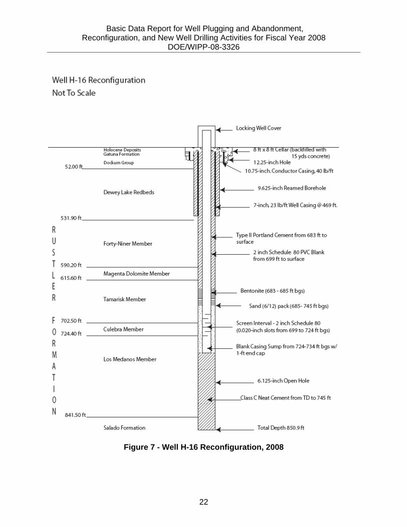
4.3 Monitoring Well H-16 The FY 2008 work plan outlined procedures to reconfigure this well. The objective was to remove all well appurtenances, tubing, and inflatable packers; backfill the existing cellar around the wellhead; PBTD of the well; and install 2-inch well casing for a dedicated groundwater monitoring well in the Culebra Member of the Rustler Formation. H-16 is located inside the WIPP compound fenced area, approximately 50 feet northwest of the Air Intake Shaft (AIS). Signage and yellow caution tape around the perimeter of the work area established work zone barriers to unauthorized personnel. All authorized personnel were required to read and sign the minutes of the daily safety meeting when entering the location. WRES and DOE provided daily safety inspections, and any concerns were corrected before work continued. The STR provided a Hot Work Permit so that a welding and cutting torch could be used if necessary. In addition, work was not performed during AIS inspections. H-16 was originally completed to monitor isolated intervals of interest in the Rustler Formation to a total depth of 850.9 feet bgs. A 9.625-inch borehole was drilled to a total depth of 469 feet bgs, and 7-inch steel casing was set and cemented in place. A 6.125-inch borehole was then advanced to 850.9 feet bgs to the top of the Salado Formation. The open hole was then completed with 2.375-inch tubing string with five inflatable packers and five transducers to a total depth of 747.5 feet bgs. Stainless steel 0.25-inch tubing was attached to each packer and each transducer, terminating in a concrete-lined 8- by 8-foot surface well vault. The stainless steel tubing allowed monitoring of the inflatable packers and transducers independently over time. In addition, a 0.75-inch PVC pipe was run along the outside of the tubing/packer string to an unknown total depth. The plan for removing the 2.375-inch tubing string and the five down-hole packers included taking all the weight off the tubing and packers with rig draw works, then deflating each packer and removing all equipment to the surface. A Weatherford overshot was used to latch onto the 2.375-inch tubing. During the driller’s initial attempt to pick up on the tubing/packer string, the tubing string parted and only 3.2 feet of tubing was retrieved. The tubing was highly corroded, which caused concern about the structural integrity of the existing tubing in the well. The driller used a Weatherford tubing spear and latched onto the tubing/packer six additional times as the tubing continued to part. Pieces of recovered tubing varied in length from 0.6 feet to 3.9 feet until tubing integrity improved and the entire remaining length of the tubing/packer string could be picked up. The tubing/packer string lifted at 70,000 psi of tension from draw works on the rig to allow packer deflation and removal. During removal, the tubing/packer string became stuck at 470 feet bgs. A set of 3-inch Weatherford hydraulic jars was attached to the tubing/packer string to unseat the stuck tubing/packer string. Jars load hydraulic pressure onto a seated hammer and when released, apply the stored energy to the tubing string in an upward force. With the jars, the string became unstuck, and when the tubing string was removed from the hole, it was found that a 0.75-inch piece of PVC pipe, used for water level measurement, had become wedged between the top of Packer #5 (uppermost packer) and the side of the 7-inch
Basic Data Report for Well Plugging and Abandonment, Reconfiguration, and New Well Drilling Activities for Fiscal Year 2008 DOE/WIPP-08-3326
21
casing. Removal of all tubing, packers, stainless steel tubing, and transducers was completed. After release of the packers, the static water level was monitored to confirm that hydrostatic pressure was maintained in the borehole. The static water level remained constant at 72 feet bgs during the entire process, confirming consistent hydrostatic pressure. H-16 was prepared for completion as a dedicated groundwater monitoring well in the Culebra Member. A 10-inch diameter J-55 grade steel casing with a foot plate was placed from the floor of the surface vault to 3 feet above surface grade and secured around the outside of the existing 7-inch well casing. The 8- by 8-foot cellar was then filled with 15 cubic yards of Portland Type II aggregate concrete to the surface. The concrete was allowed to set overnight. The driller placed 2.375-inch tubing in the borehole to 853 feet bgs. The well was circulated with fresh water until return water was clear and all deleterious material had been removed from the casing and the open hole. A 24-sack Class C neat cement mix was prepared in a tub and positively displaced through tubing from the total depth to 745 feet bgs. Well circulation was maintained throughout the process. The cement weight, monitored throughout the process was consistently 14.7 lb/gal. The cement was allowed to set overnight. The 2-inch Schedule 80 threaded PVC well casing was prepared to place in the hole. An end plug and 10 feet of blank casing were placed at a total depth of 734 feet bgs, 25 feet of 0.020-inch slotted screen was placed from 724 feet bgs to 699 feet bgs, and 2-inch schedule 80 blank casing was placed to the surface. A 1.5-inch tremmie pipe was placed down the annulus from 689 feet bgs to the surface. A 6/12 Colorado sand pack was positively placed through the tremmie in the annulus from the total depth at 745 feet bgs to the top of the sand at 685 feet bgs. A 2-foot bentonite seal plug was positively placed through the tremmie on top of the sand pack from 685 feet bgs to 683 feet bgs. An Enviro-Grout slurry was mixed in a large tub and was positively displaced through the tremmie from the top of the bentonite plug to the surface. The Enviro-Grout slurry, monitored for weight throughout the process, was 9.4 to 9.7 lb/gal. The well was ready to be developed for clearing perforations and recovering any work water that remained. The well development is discussed in Section 6.0 of this report. Figure 7 shows the final configuration of well H-16.
Basic Data Report for Well Plugging and Abandonment, Reconfiguration, and New Well Drilling Activities for Fiscal Year 2008 DOE/WIPP-08-3326
22
Figure 7 - Well H-16 Reconfiguration, 2008
Well H-16 Reconfiguration
Not To Scale
52.00 Dockum G10up
Dewey lake Redbeds
531.90 ft
R
u Forty- Niner Member
s T 590.20 ft
L 615.60 ft Magenta Dolomite Member
E
R Tamarisk Member
F 702.50 ft
0 724.40 11 Culebra Member
R
M los Medanos Member A T I 0 N 841.50 ft
Salado Formation
locking Well Cover
1 2.25-inc h Hole 15 yds concrete)
1 0.75-inch. Conductor Casing,40 lblft
9.625-inch Reamed Borehole
7-inch, 23 lblft Well Casing @469ft.
Type II Portland Cement from 683ft to surface
2 inch Schedule 80 PVC Blank from 699 ft to surface
Bentonite (683 -685 ft bgs)
Sand (6/1 2) pack (685- 745 ft bgs)
Screen Interval - 2 inch Schedule 80 (0.020-inch slots from 699 to 724ft bgs)
Blank Casing Sump from 724-734 ft bgs w/ 1-ftendcap
6. 125-inch Open Hole
C Neat Cement from TD to 7 45 ft
Total Oepth 850.9ft

Basic Data Report for Well Plugging and Abandonment, Reconfiguration, and New Well Drilling Activities for Fiscal Year 2008 DOE/WIPP-08-3326
23
5.0 NEW MONITORING WELL DRILLING AND COMPLETION The FY 2008 field program called for the drilling and completion of two new groundwater monitoring wells, designated H-6bR and H-15R, replacing H-6b and H-15 (Culebra), respectively. The objective was to provide dedicated groundwater monitoring in the Culebra Member of the Rustler Formation. 5.1 New Monitoring Well H-15R H-15R is located in Section 28, Township 22 South, Range 31 East in Eddy County, New Mexico. The location is 50 feet south of H-15 (now a Magenta well, see Subsection 4.2). The H-15 location was enlarged and the surface stabilized to accept additional heavy drilling equipment. The location area comprises approximately 1.75 acres capped with caliche-base coarse material. Improvements to the existing access road were made with caliche-base coarse material to stabilize the road base to accept heavy drilling equipment. An 18-inch borehole was drilled with an auger drill rig, and 12.75-inch J-55 steel surface casing was set and cemented in place. The total depth of surface casing at H-15R was 31 feet bgs. The surface casing was cemented in place with Type II Portland neat cement until observed at the surface (see Figure 8). The cement was allowed to set for minimum of 24 hours before the well bore was advanced.
Figure 8 - Surface Casing at H-15R
An 11-inch borehole was advanced by air rotary drilling methods with a Failing 2500 Series drill rig. H-15R was drilled to a total depth of 924 feet bgs. Penetration rates varied from 0.6 feet per minute at shallow depths to 0.2 feet per minute at maximum depth. Groundwater was encountered during the drilling of this well. H-15R penetrated shallow minor groundwater in the Dewey Lake Redbeds at a depth of 210 feet to 230 feet bgs

Basic Data Report for Well Plugging and Abandonment, Reconfiguration, and New Well Drilling Activities for Fiscal Year 2008 DOE/WIPP-08-3326
24
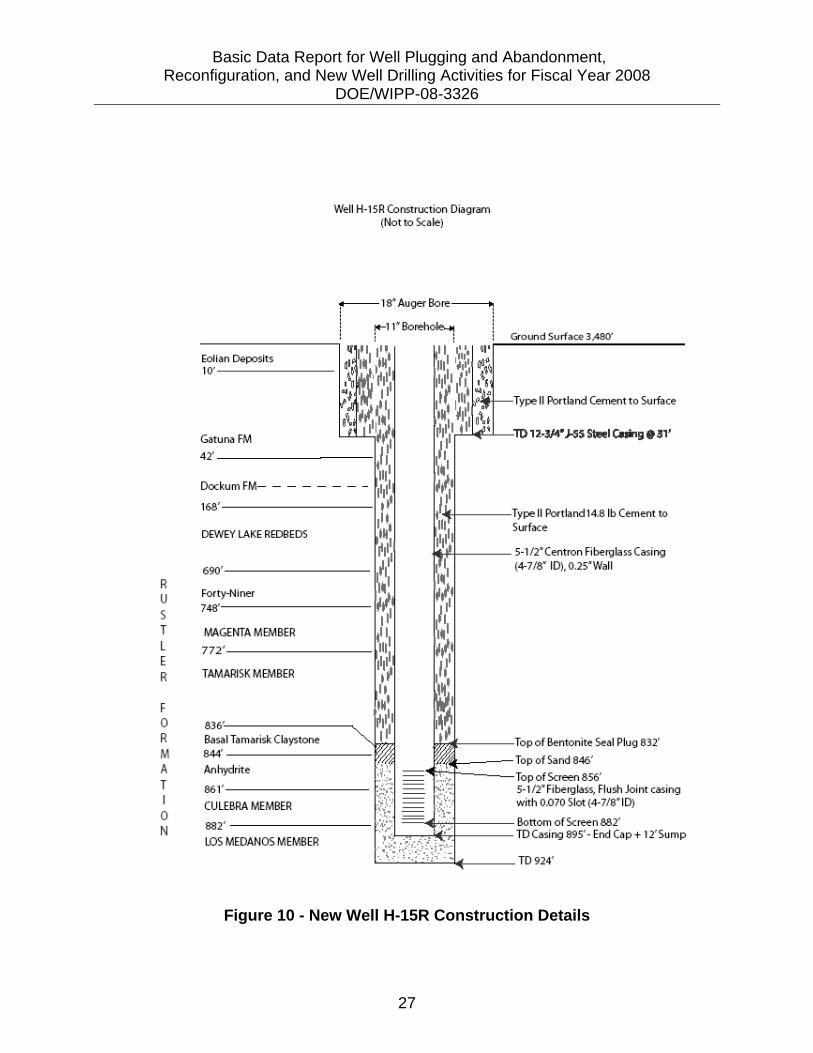
and more significant groundwater in the Magenta Dolomite Member at a depth of 748 feet to 772 feet bgs. Open-hole geophysical logging was performed in H-15R. The geophysical log of H-15R included gamma ray, short normal resistivity, and dual and medium induction resistivity. A caliper log was not included in H-15R because of mechanical failure of the tool while logging. The geophysical log revealed the objective Culebra Member interval at 882 feet to 858 feet bgs in H-15R. The well casing used for well completions was Centron 5.5-inch fiberglass threaded joints with 0.25-inch wall thickness. Each casing joint was measured at 29 feet in length. Slotted screen was 0.070-inch and the vertical screened interval measured 27 feet in length. An end cap was placed below a 10-foot joint of blank pipe to provide a sump below the screened interval and then 29 feet of blank casing was placed above the screened interval to bring the well casing to the surface. The screened interval was placed in H-15R from 882 feet to 855 feet bgs. Figure 9 shows the 5.5-inch casing being set in H-15R.
Figure 9 - Setting 5.5-Inch Fiberglass Casing at H-15R
The annulus for the well was filled with very coarse sand (gradation #10 or less) across the screened interval, a bentonite seal plug above the top of the sand pack, and Portland Type II 15.0 lb/gal cement to the surface. A 2.375-inch tremmie pipe was placed in the annulus to provide the placement for the sand pack, bentonite plug, and cement. The top of sand in H-15R was confirmed at 846 feet bgs by loss returns in

Basic Data Report for Well Plugging and Abandonment, Reconfiguration, and New Well Drilling Activities for Fiscal Year 2008 DOE/WIPP-08-3326
25
circulation in the well casing as sand was being positively displaced down the tremmie. A bentonite seal plug and Portland Type II cement were positively placed above the sand pack in each well. Cement was monitored and consistently weighted 14.8 lb/gal. The well diagram for H-15R is depicted in Figure 10. H-15R was developed by bailer and airlift methods. Well development procedures are discussed in Section 6.0 of this report. 5.2 New Monitoring Well H-6bR H-6bR is located in Section 18, Township 33 South, Range 31 East in Eddy County, New Mexico. The well is located 50 feet west-southwest of H-6 (now plugged and abandoned, see Subsection 3.2). The existing H-6 location pad and access road were used for the new well drilling operation. The existing well pad covers approximately two acres surrounded by natural terrain and vegetation. An 18-inch borehole was drilled with an auger drill rig, and 12.75-inch J-55 steel surface casing was set and cemented in place. The total depth of surface casing at H-6bR was 35 feet bgs. The surface casing was cemented in place with Type II Portland neat cement until observed at the surface (see Figure 8). The cement was allowed to set for minimum of 24 hours before the well bore was advanced.
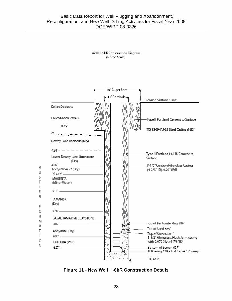
An 11-inch borehole was advanced by air rotary drilling methods with a Failing 2500 Series drill rig. H6bR was drilled to a total depth of 663 feet bgs. Penetration rates were similar to H-15R and varied from 0.6 feet per minute at shallow depths to 0.2 feet per minute at maximum depth. Groundwater was encountered during the drilling of H-6bR. H-6bR did not penetrate groundwater until the Magenta Member at a depth of 492 feet to 511 feet bgs. Open-hole geophysical logging was performed in the H-6bR borehole. The geophysical log of H-6bR included gamma ray, short normal resistivity, dual and medium induction resistivity, and three-arm caliper. The caliper log of H-6bR revealed two areas of washout in the borehole. The Forty-niner Member was washed out from 11-inch borehole size to beyond the scale that the caliper log was capable of measuring (20-inch diameter) at 455 feet to 465 feet bgs. The basal claystone of the Tamarisk Member was washed out from 11-inch borehole size to 15.5-inches at 575 feet to 585 feet bgs. The geophysical log revealed the objective Culebra Member interval at 603 feet to 627 feet bgs in H-6bR. The well casing used for well completions was Centron 5.5-inch fiberglass threaded joints with 0.25-inch wall thickness. Each casing joint was measured at 29 feet in length. Slotted screen was 0.070-inch and the vertical screened interval measured 27 feet in length. An end cap was placed below a 10-foot joint of blank pipe to provide a sump below the screened interval and then 29 feet of blank casing was placed above the screened interval to bring the well casing to the surface. The screened interval was placed in H-6bR from 628 feet to 601 feet bgs.

Basic Data Report for Well Plugging and Abandonment, Reconfiguration, and New Well Drilling Activities for Fiscal Year 2008 DOE/WIPP-08-3326
26
The annulus was filled with very coarse sand (gradation #10 or less) across the screened interval, a bentonite seal plug above the top of the sand pack, and Portland Type II 15.0 lb/gal cement to the surface. A 2.375-inch tremmie pipe was placed in the annulus to provide positive placement for the sand pack, bentonite plug, and cement. Top of sand in H-6bR was measured at 589 feet bgs with a steel measuring tape. A bentonite seal plug and Portland Type II cement were placed above the sand pack in each well. Cement was monitored and consistently weighted 14.8 lb/gal. Well diagram for H-6bR is depicted in Figure 11. Well development procedures are discussed in Section 6.0 of this report.
Basic Data Report for Well Plugging and Abandonment, Reconfiguration, and New Well Drilling Activities for Fiscal Year 2008 DOE/WIPP-08-3326
27
Figure 10 - New Well H-15R Construction Details
R u s T L E R
F 0 R M A T I 0 N
Well H-15R Co nst ruction Diagram (Not to Scale )
r-,· 18'Auger
,.... 1 1' Bore;hole,_.
------------------,: ! Ground Surface
Eolian Deposits 10'-------
Gatuna FM
42'---------U
Dockum FM- - - - - - - -
168'---------1
DEWEY LAKE REDBEDS
690'--------
Forty-N i ner 748''---------
MAGENTA MEMBER
772'--------
TAMARISK MEMBER
Basal Tamarisk Claystone 844'--------Anhydrite
861'---------
CULEBRA MEMBER
882' -------
LOS MEDANOS MEMBER
1 1'~&-------l~'P• II Portland14.8 1b Cement to Surface
l4:1'+------- 5-1 /l'Centron Fiberglass Casing (4-7/8' ID),0.25'Wall
IJ7.~-------Top of Bentonite Seal Plug 832'
==~~~===!:~of Sand 846' of Screen856'
5-1 /l'Fiberglass, Flush Joint casing with 0.070 Slot (4-7/8' 1D)
==..em+------- Bottom of Screen882' : <r==.JiE'ti-------- TD Casing 895' - End Cap + 1 2'Sump
~:£.:..:_:,;_.:.'-"-~f--- TD 924'
Basic Data Report for Well Plugging and Abandonment, Reconfiguration, and New Well Drilling Activities for Fiscal Year 2008 DOE/WIPP-08-3326
28
Figure 11 - New Well H-6bR Construction Details
R u s T L E R
F 0 R M A T I 0 N
Well H-6 bR Construction Diagram (Not to Scale(
r---18' Auger Bore---o,
,._ 1 1' Borehole..ot ! ! Ground Surface 3,348'
Eolian Deposits
Caliche and Gravels
(Dry)
Dewey Lake Redbeds (Dry)
424'- - - - - - - - - -
Lower Dewey Lake Limestone (Dry)
456'---------Forty-Niner ?? (Dry)
?? 472' --------MAGENTA (Minor Water)
TAMARISK (Dry)
578'---------
BASAL TAMARISK CLAYSTONE
586' --------
Anhydrite (Dry)
603'--------
CULEBRA (Wet)
627'---------
14-l'f---- 5-1 /l'Cent ron Fiberglass Casing (4-7/8' ID),0.25'Wall
+----Top of Bentonite Plug 586'
::::::~~~===~:~of Sand 589' of Screen601 '
/l'Fiberglass, Flush Joint casing with 0.070 Slot (4-7/8'1D)
==...tm-+---- Bottom of Screen627' ;.:r-,.,.....,.;l.iE"r..----- TD Casing 639' - End Cap+ 1 2'Sump

Basic Data Report for Well Plugging and Abandonment, Reconfiguration, and New Well Drilling Activities for Fiscal Year 2008 DOE/WIPP-08-3326
29
6.0 WELL DEVELOPMENT In addition to development of the new monitoring wells and reconfigured wells, two wells were developed to restore the density of the formation water. Wells CB-1 and DOE-2 were reconfigured in 2004. During this process the wells were converted to monitor only the Bell Canyon Formation using a PIP installation. After the installation, water used to inflate the packer remained in the tubing, altering the natural fluid density of the formation. During the FY 2008 program these two wells were developed until filed measure density readings reflected formation densities. This section describes the methods of development for these wells, new wells, and reconfigured wells. Each well was developed to remove all workover water and any remaining deleterious material in the well casing from the completion processes and to expose the well casing to formation water from the zone of interest. Three types of well development methods were used for this process. In DOE-2 and CB-1, which were deeper completions than the other wells, the swabbing method with an oil field workover rig was used for development. In all other wells, bailer and/or air lift development methods were used, based on well production, depth of completion, and well casing diameters (Figure 12). Groundwater density measurements were used to confirm that formation water was present in the well throughout the development process. Historical data of formation water densities was supplied by the STR to establish baseline groundwater densities. The table below shows the well development methods, recovered water volumes, and initial and final recorded water density for each well.
Table 1 - Well Development Methods
Well Name Development Method
Volume Recovered (gallons)
Initial Density (g/cm3)
Final Density
(gm/cm3) DOE-2 Swab 5,060 0.999 1.104 CB-1 Swab 16,590 0.998 1.127 AEC-7 Air Lift 2,555 1.040 1.040 H-15 Air Lift 220 0.998 1.070 H-16 Air Lift 155 1.035 1.037 H-15R Bailer 3,200 1.070 1.124 H-6bR Bailer 3,659 1.007 1.036

Basic Data Report for Well Plugging and Abandonment, Reconfiguration, and New Well Drilling Activities for Fiscal Year 2008 DOE/WIPP-08-3326
30
Figure 12 - Air Lift Well Development at H-15
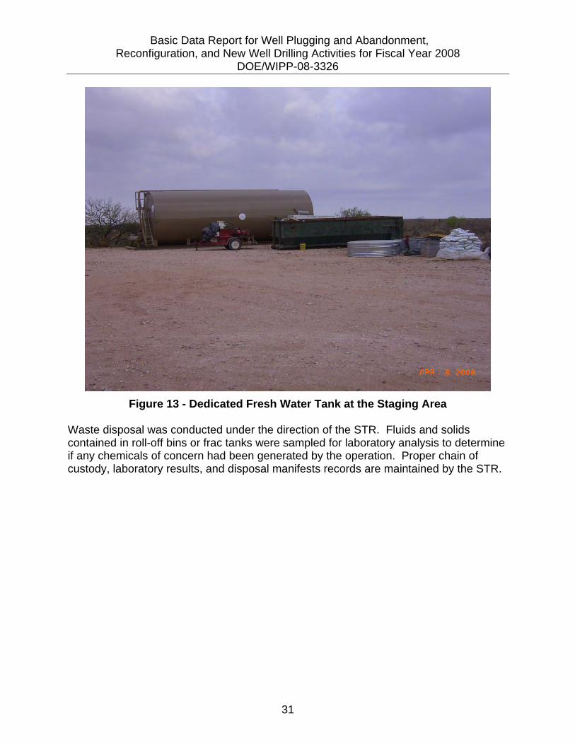
7.0 WASTE MANAGEMENT All drilling and completion, reconfiguration, and plug and abandonment processes used a closed loop system to control fluids and solids. Air rotary drilling generated drill cuttings that required a 6-inch flexible hose to be run from the return flow nipple at the drilling rig to metal roll-off bins covered with 6-mil plastic. Well completions, reconfigurations, and plug and abandonment processes generated work water and formation water that required 4-inch flexible hose from a submersible pump placed in a 100-gallon metal tub at the end of the return flow nipple at the drilling rig to fully enclosed 500-barrel metal frac tanks. Fresh water used during each process was brought to the location in a dedicated water truck with a 3,200-gallon capacity (see Figure 13). Fresh water was stored in a clean fully enclosed 500-barrel metal frac tank (see Figure 14). The fresh water tank was located approximately 1 mile south of the WIPP compound, at the staging area for all drilling and well equipment.
Basic Data Report for Well Plugging and Abandonment, Reconfiguration, and New Well Drilling Activities for Fiscal Year 2008 DOE/WIPP-08-3326
31
Figure 13 - Dedicated Fresh Water Tank at the Staging Area
Waste disposal was conducted under the direction of the STR. Fluids and solids contained in roll-off bins or frac tanks were sampled for laboratory analysis to determine if any chemicals of concern had been generated by the operation. Proper chain of custody, laboratory results, and disposal manifests records are maintained by the STR.

Basic Data Report for Well Plugging and Abandonment, Reconfiguration, and New Well Drilling Activities for Fiscal Year 2008 DOE/WIPP-08-3326
32
Figure 14 - Frac Tank Being Delivered to Location