
BASIC CIRCUIT ANALYSIS Presentation by Jon Josten, Colin Brown, Ava Zebzda and Joseph Hemmingson.
34
BASIC CIRCUIT ANALYSIS Presentation by Jon Josten, Colin Brown, Ava Zebzda and Joseph Hemmingson
-
Upload
abigayle-dickerson -
Category
Documents
-
view
216 -
download
0
Transcript of BASIC CIRCUIT ANALYSIS Presentation by Jon Josten, Colin Brown, Ava Zebzda and Joseph Hemmingson.
BASIC CIRCUIT ANALYSIS
Presentation by Jon Josten, Colin Brown, Ava Zebzda and Joseph Hemmingson

Circuit Analysis Topics
■Circuit Elements & Variables
■Ohm's Law
■Kirchhoff's Laws
■Mesh Current Analysis

Why are we doing this?
■ We have to introduce various basic elements, variables, and laws of circuit analysis in order to get to a point where we can perform Mesh Current Analysis in order to find the values of current going through any point of a circuit. Once we have these building blocks, we can develop a system of equations that describe a circuit which can be put into matrix form and solved using what we’ve learned about matrices.
■ Being able to find the values for current can tell you a lot about a circuit. It is a few simple calculations away from finding voltage and power, which at the end of the day can also be used to calculate how much money operating electronics may cost.

CIRCUIT ELEMENTS & VARIABLES
Voltage, Ground, Current, Resistance, Wires, Nodes

Voltage
Units: Volts
(V)
Symbol: V
Circuit Element:
■ Water analogy – Voltage Pressure.
■ color convention is blue.
■ For our analysis, each point we measure is going to have a constant voltage associated with it.
■ Current is proportional to the difference in voltage between two points.

Current
Units: Amperes
(A)
Symbol: I
Circuit Element:
■ Water Analogy: Current Water/Time
■ the rate at which charge is transferred through an element or wire
■ caused by a difference in voltage between two locations
■ Current flows from high voltage to low voltage
■ color convention is red
■ Imagine which direction water would flow in the picture below due to pressure

Resistance
Units: Ohms
(Ω)
Symbol: R
Circuit Element:
■ Water Analogy: Resistance Narrowness of pipe
■ a measure of the degree to which an object opposes the flow of charges through it.
■ similar to friction in Physics (opposing force).

Wires & Nodes
■ A path must connect circuit elements so that current can flow between points on the circuit. This path is the wire in which current is able to flow.
■ A Node is an intersection of paths on a circuit. There is typically a voltage represented at each node.
■ There is no voltage difference between two nodes connected only by wire. They can be thought of as one node.

Circuit ■ A circuit is elements connected together so that current is able to flow. (i.e. a loop that has different voltages throughout it)
https://cdn.sparkfun.com/assets/3/4/6/4/e/511bc192ce395f3941000002.gif

Thomas Edison
Invented the lightbulb, has 1,093 patents and electrocuted an Elephant in the process of advocating DC current.

OHM'S LAWOhm’s Law Definition, Solving Circuit#1 with Ohm’s Law

Ohm's Law: Definition
■V = IR
■Where 'V' is voltage, 'I' is current, and 'R' is resistance
■Voltage across a resistor is equal to the current through the resistor multiplied by its resistance value Arrow denotes current
flow, plus & minus signs denote voltage
drop-+

Circuit #1: Ohm's Law (V=IR)
■ The way the voltage source is applied here, we can see that there is a difference of 6 volts between the two nodes of the resistor. Looking only at the resistor, we can use ohm’s law to calculate the current.

Circuit #1: Ohm's Law

Circuit #1: Ohm's Law
I

Georg Ohm
Ohm's law was first founded by Henry Cavendish, but since he did not publish his discoveries on electricity during his lifetime, the credit went to Ohm in 1879 when he had independently made the discovery, and published it himself.

KIRCHHOFF’S LAWSKVL, KCL, Series versus Parallel Circuits

Kirchhoff’s Voltage Law
■ The sum of the voltages going around any loop in a circuit is zero
V1 + V2 + V3 = VS

Circuit #2: KVL
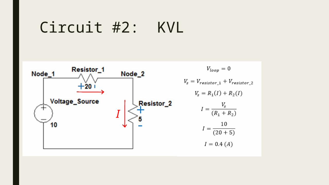
Circuit #2: KVL
I

Circuit #3: KVL
V

Series Circuits
I

Parallel CircuitsV

Kirchhoff’s Current Law
■ The total amount of current going into any node is equal to the amount of current going out.
i2 + i3 = i1 + i4

Circuit #3: KCL

Circuit #3: KCL I
𝑖1 𝑖2
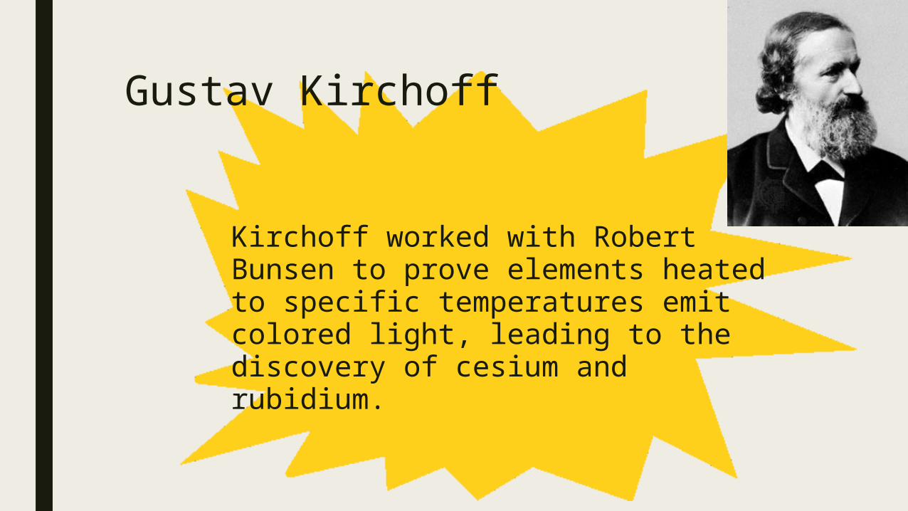
Gustav Kirchoff
Kirchoff worked with Robert Bunsen to prove elements heated to specific temperatures emit colored light, leading to the discovery of cesium and rubidium.

MESH CURRENT ANALYSIS
Mesh Current Analysis, Circuit #4, Representing Solutions as a System of Equations, Equivalent Matrix Equation

Mesh Current Analysis Theory
The Mesh Current method uses Kirchhoff's Voltage Law and Ohm's Law to solve for the unknown current around a mesh.
This is useful to limit the number of equations and unknowns in the final result.
Def'n: A Mesh is the loop that doesn't contain any other loops within.

Steps for Mesh Current Analysis
1. Label each mesh of the circuit with a mesh current, going in the clockwise direction.
2. Write KVL equations for each mesh. Each term is a voltage, but will write the terms using Ohm's law to put them in terms of the mesh currents.
3. Solve for the unknown currents using an augmented matrix

Circuit #4: Mesh Current Analysis
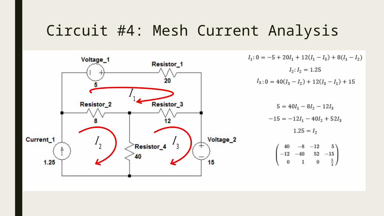
Circuit #4: Mesh Current Analysis
𝐼 2 𝐼 3
𝐼 1

Circuit #4: Matrix Equation
𝐼 2 𝐼 3
𝐼 1
Sources
Node Voltage Analysis Process: http://www.allaboutcircuits.com/textbook/direct-current/chpt-10/node-voltage-method/
Voltage, Current, Resistance, and Ohm's Law: https://learn.sparkfun.com/tutorials/voltage-current-resistance-and-ohms-law http://physics.info/electric-current/ http://physics.info/circuits-v/ Resistors: https://learn.sparkfun.com/tutorials/resistors