Basic AutoSketch Manual - boeingconsult.com · Basic AutoSketch Manual Instruction for students ....
13
Karl Boeing Skf-Manual.doc 1 of 13 Basic AutoSketch Manual Instruction for students
Transcript of Basic AutoSketch Manual - boeingconsult.com · Basic AutoSketch Manual Instruction for students ....

Karl Boeing
Skf-Manual.doc 1 of 13
Basic AutoSketch Manual
Instruction for students
Karl Boeing
Skf-Manual.doc 2 of 13
Contents BASIC AUTOSKETCH MANUAL ............................................................................................................................ 1 INSTRUCTION FOR STUDENTS ............................................................................................................................ 1 BASIC AUTOSKETCH INSTRUCTION .................................................................................................................. 3 SCREEN LAYOUT ...................................................................................................................................................... 3
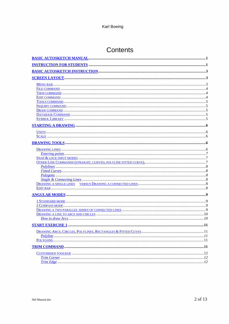
MENU BAR .................................................................................................................................................................. 3 FILE COMMAND .......................................................................................................................................................... 4 VIEW COMMAND ........................................................................................................................................................ 4 EDIT COMMAND .......................................................................................................................................................... 4 TOOLS COMMAND ....................................................................................................................................................... 5 INQUIRY COMMAND .................................................................................................................................................... 5 DRAW COMMAND ....................................................................................................................................................... 5 DATABASE COMMAND ............................................................................................................................................... 5 SYMBOL LIBRARY ...................................................................................................................................................... 5
STARTING A DRAWING .......................................................................................................................................... 6 UNITS ......................................................................................................................................................................... 6 SCALE ........................................................................................................................................................................ 6
DRAWING TOOLS ..................................................................................................................................................... 6 DRAWING LINES ......................................................................................................................................................... 6
Entering points ...................................................................................................................................................... 7 SNAP & LOCK INPUT MODES ....................................................................................................................................... 7 OTHER LINE COMMANDS (STRAIGHT, CURVED, POLYLINE FITTED CURVE), ................................................................ 7
Polylines ............................................................................................................................................................... 8 Fitted Curves......................................................................................................................................................... 8 Polygons ............................................................................................................................................................... 8 Single & Connecting Lines ................................................................................................................................... 8
DRAWING A SINGLE LINES VERSUS DRAWING A CONNECTED LINES ........................................................................ 8 EDIT BAR .................................................................................................................................................................... 8
ANGULAR MODES .................................................................................................................................................... 9 1 STANDARD MODE .................................................................................................................................................... 9 2 COMPASS MODE ....................................................................................................................................................... 9 DRAWING A TWO PARALLEL SERIES OF CONNECTED LINES ......................................................................................... 9 DRAWING A LINE TO ARCS AND CIRCLES .................................................................................................................. 10
How to draw Arcs ............................................................................................................................................... 10 START EXERCISE 1 ................................................................................................................................................ 11
DRAWING ARCS, CIRCLES, POLYLINES, RECTANGLES & FITTED CUVES .................................................................. 11 Polyline ............................................................................................................................................................... 11
POLYGONS ................................................................................................................................................................ 11 TRIM COMMAND .................................................................................................................................................... 11
CUSTOMISED TOOLBAR ............................................................................................................................................ 12 Trim Corner ........................................................................................................................................................ 12 Trim Edge ........................................................................................................................................................... 12
Karl Boeing
Skf-Manual.doc 3 of 13
Basic AutoSketch Instruction
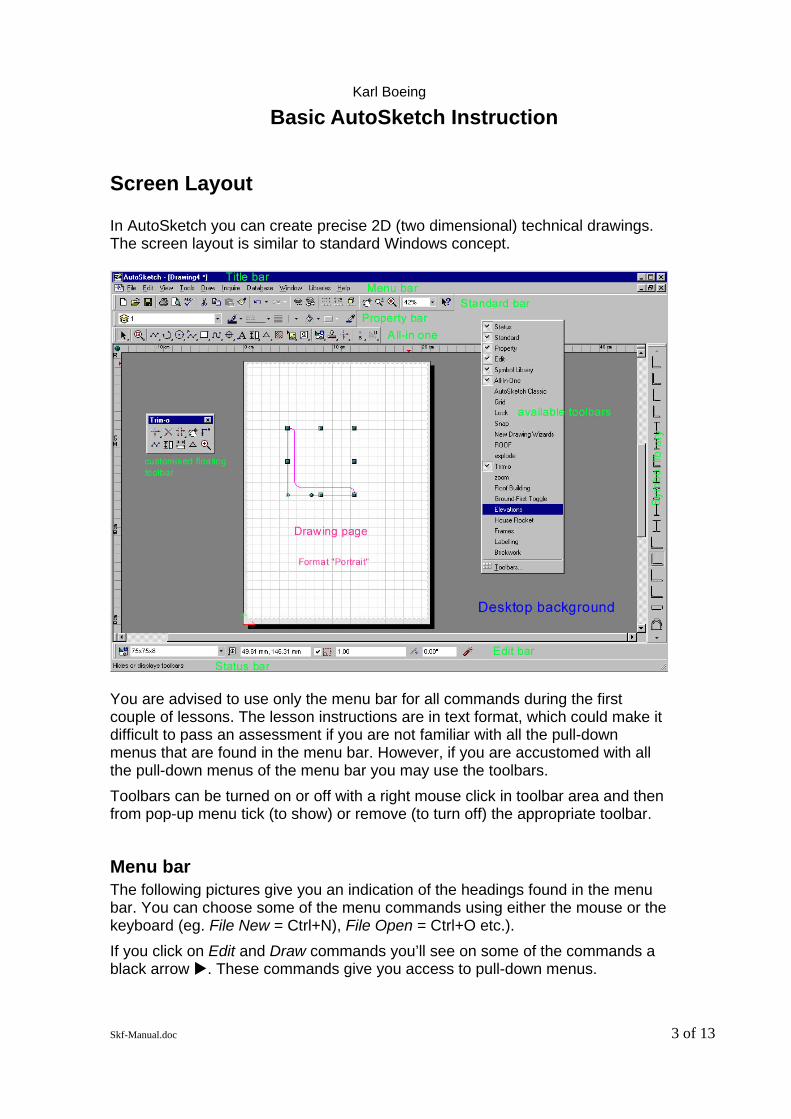
Screen Layout In AutoSketch you can create precise 2D (two dimensional) technical drawings. The screen layout is similar to standard Windows concept.
You are advised to use only the menu bar for all commands during the first couple of lessons. The lesson instructions are in text format, which could make it difficult to pass an assessment if you are not familiar with all the pull-down menus that are found in the menu bar. However, if you are accustomed with all the pull-down menus of the menu bar you may use the toolbars. Toolbars can be turned on or off with a right mouse click in toolbar area and then from pop-up menu tick (to show) or remove (to turn off) the appropriate toolbar.
Menu bar The following pictures give you an indication of the headings found in the menu bar. You can choose some of the menu commands using either the mouse or the keyboard (eg. File New = Ctrl+N), File Open = Ctrl+O etc.). If you click on Edit and Draw commands you’ll see on some of the commands a black arrow . These commands give you access to pull-down menus.

Karl Boeing
Skf-Manual.doc 4 of 13
File command
Look at all the commands you find in the File heading To start a new drawing you should select a size for your drawing. In most cases we’ll use the Landscape format You can show how many recently files should be shown (that’s done in Drawing Option)
View command
The View command is usually used for zooming.
Ctrl+plus (+) = zooming in Ctrl+minus = zooming out
Pan moves a drawing in a pane by selecting two points
To do dimensioning you often have to zoom in and to get back to your original drawing. If you zoom in, Ctrl+L will return to the previous view
Edit command The Edit Command is the command that you will be
using most frequently Select is seldom used. If there is a dashed rectangle on your drawing Select Marquee will delete it Get familiar with Transform and Trim Command because these are the most
frequent use commands

Karl Boeing
Skf-Manual.doc 5 of 13
Tools command
Tools command is used to set up 1st Drawing Options (Units and Scale and other settings) 2nd Graphic Options (Layers)
Inquiry command
If you want to know information about an entity you need either to select the entity first and then access the Inquire command or click on Inquire command and then select the entity.
Draw command
Draw commands are the commands that need to be known by heart. Refer also to snap points. When all else fails hit the S-key to change to Snap Off.
Database Command
Window command
The Database command is not used in CAD 1 and 2
The Window command indicates how many drawing files are currently being used. You can show them all if you select Tile (horizontally, vertically or cascade)
Symbol Library
The library is used to insert symbols like windows, doors, furniture etc. You can access the library from Draw Symbol
Explore
The first step is to get familiar with the AutoSketch screen and all commands found on the menu bar.
Karl Boeing
Skf-Manual.doc 6 of 13
When you start the program (open it) a blank screen will be shown. As with all the computer programs
Starting a Drawing AutoSketch is an easy CAD-Program. If you are familiar with technical drawings you you’ll soon start producing simple CAD-drawings. There are a few basic settings to be made before you start your drawing.
• First you need to select an appropriate Paper size (eg. A4, A3 etc.) and the drawing Orientation (Landscape or Portrait)
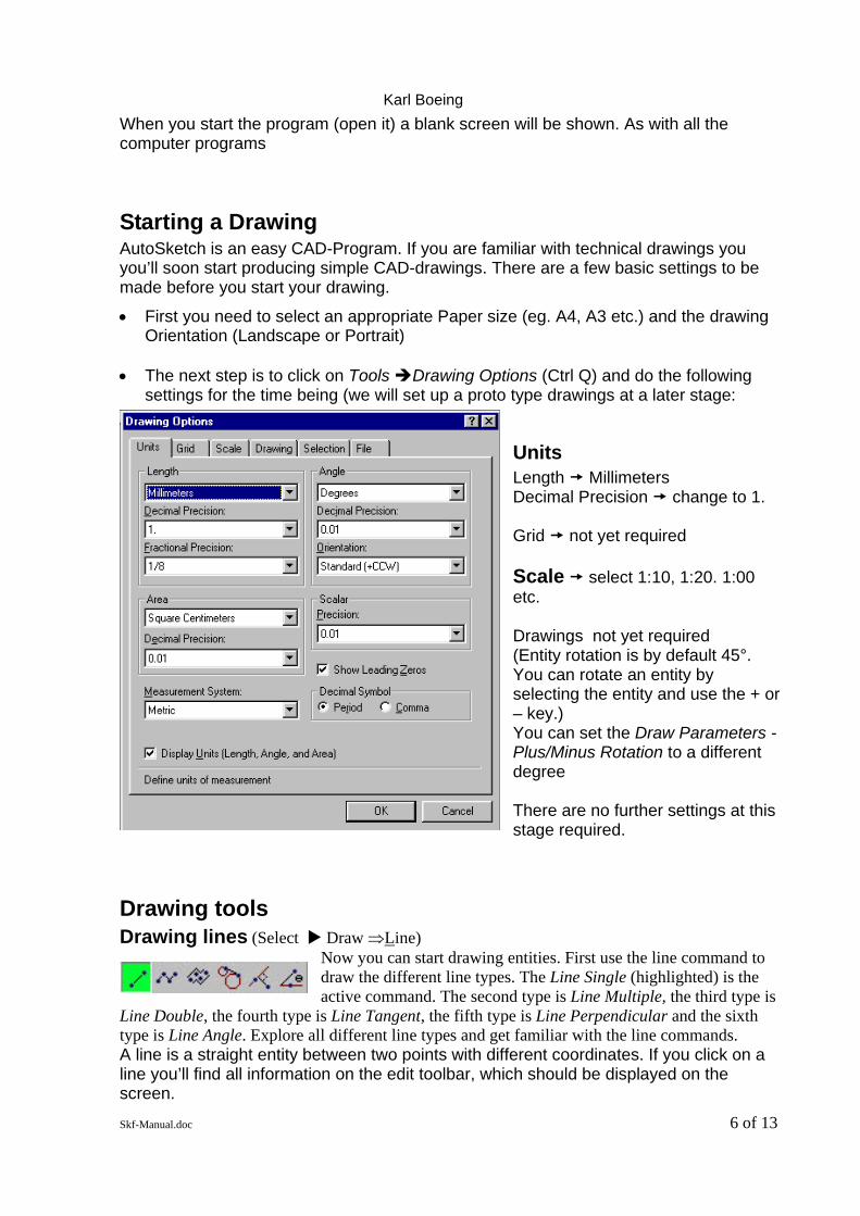
• The next step is to click on Tools Drawing Options (Ctrl Q) and do the following
settings for the time being (we will set up a proto type drawings at a later stage:
Units Length Millimeters Decimal Precision change to 1. Grid not yet required Scale select 1:10, 1:20. 1:00 etc. Drawings not yet required (Entity rotation is by default 45°. You can rotate an entity by selecting the entity and use the + or – key.) You can set the Draw Parameters - Plus/Minus Rotation to a different degree There are no further settings at this stage required.
Drawing tools Drawing lines (Select Draw ⇒Line)
Now you can start drawing entities. First use the line command to draw the different line types. The Line Single (highlighted) is the active command. The second type is Line Multiple, the third type is
Line Double, the fourth type is Line Tangent, the fifth type is Line Perpendicular and the sixth type is Line Angle. Explore all different line types and get familiar with the line commands. A line is a straight entity between two points with different coordinates. If you click on a line you’ll find all information on the edit toolbar, which should be displayed on the screen.

Karl Boeing
Skf-Manual.doc 7 of 13
Entering points A line must have a start and an end point. For other entities you may have to select more points to complete the entity. (an arc requires 3 points or 2 points and a center point etc.). To move an entity, you must enter a “from” point and a “to” point. Snap modes can be accessed from the toolbar or by typing the appropriate letter using the keyboard. If the snap mode is not S or G you cannot draw a line. Hit the S-key or G-key (G snaps on grid point) and then you can select a start-point for an entity (line, arc, circle, polygon etc.).
Snap & lock input modes There are a number of input modes (snap & lock) you can choose from. S = Snap mode off G = Gridpoint input mode E = Endpoint input mode J = Jump input mode M = Midpoint input mode N = Nearest input mode B = Basepoint input mode I = Intersection input mode U = Unlock P = Perpendicular input mode C = Centerpoint input mode X = Horizontal Lock T = Tangent input mode Q = Quadrant input mode Y = Vertical Lock A = Absolute Input R = Relative Input O = Ortho Lock L = Normal Lock Locks gives you control over Horizontal-(x-directions), Vertical-(y-directions) Orthogonal-movements (both Horiz.- & Vertical-directions). The L Lock let you draw perpendicular lines to an angle of pre-determined degree. If you don’t want horizontal, vertical or perpendicular lines type U for Unlock. Unlock is the default setting and is regularly used. The cursor will always show the Snap and Lock mode that you are presently using. The cursor shows what snap and lock mode you are currently using (eg. Snap Off and Unlock or depending on your previous selection End Point and Y Coordinate (vertical)). If you can’t do anything, look at your cursor mode and press the S-key to change to Snap Off and U-key to unlock.
Other Line Commands (straight, curved, polyline fitted curve), In a broader sense drawing lines include: Lines, Arcs, Circles, Poly-lines, Polygones, Fitted Curves etc
There are the different option to draw Arcs. The first is a 3 Point Arc, the next a 2 Point Center Arc, then a2 Point Angle Arc, the Elliptical Arc Rectangle and Elliptical Arc Axes.
These are the option for drawing Circles
Karl Boeing
Skf-Manual.doc 8 of 13
Mouse
Mouse
Mouse
Mouse
MouseMouse
1
2 3
4 5 6
Mouse
1
Mouse
2
MouseMouse
3 4
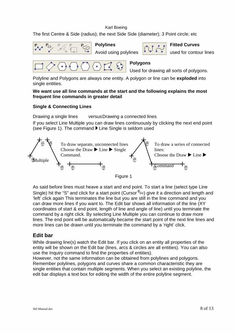
The first Centre & Side (radius); the next Side Side (diameter); 3 Point circle; etc
Polylines Avoid using polylines
Fitted Curves used for contour lines
Polygons Used for drawing all sorts of polygons.
Polyline and Polygons are always one entity. A polygon or line can be exploded into single entities. We want use all line commands at the start and the following explains the most frequent line commands in greater detail
Single & Connecting Lines
Drawing a single lines versus Drawing a connected lines If you select Line Multiple you can draw lines continuously by clicking the next end point (see Figure 1). The command Line Single is seldom used To draw separate, unconnected lines To draw a series of connected Choose the Draw Line Single lines: Command. Choose the Draw Line Multiple Command
Figure 1 As said before lines must heave a start and end point. To start a line (select type Line Single) hit the “S” and click for a start point (Cursor ) give it a direction and length and ‘left’ click again This terminates the line but you are still in the line command and you can draw more lines if you want to. The Edit bar shows all information of the line (XY coordinates of start & end point, length of line and angle of line) until you terminate the command by a right click. By selecting Line Multiple you can continue to draw more lines. The end point will be automatically became the start point of the next line lines and more lines can be drawn until you terminate the command by a ‘right’ click.
Edit bar While drawing line(s) watch the Edit bar. If you click on an entity all properties of the entity will be shown on the Edit bar (lines, arcs & circles are all entities). You can also use the Inquiry command to find the properties of entities). However, not the same information can be obtained from polylines and polygons. Remember polylines, polygons and curves share a common characteristic they are single entities that contain multiple segments. When you select an existing polyline, the edit bar displays a text box for editing the width of the entire polyline segment.
Karl Boeing
Skf-Manual.doc 9 of 13
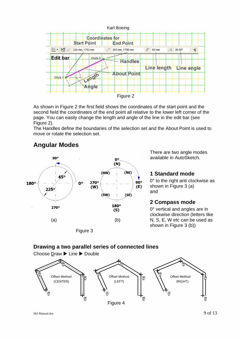
Figure 2
As shown in Figure 2 the first field shows the coordinates of the start point and the second field the coordinates of the end point all relative to the lower left corner of the page. You can easily change the length and angle of the line in the edit bar (see Figure 2). The Handles define the boundaries of the selection set and the About Point is used to move or rotate the selection set.
Angular Modes There are two angle modes available in AutoSketch.
1 Standard mode 0° to the right anti clockwise as shown in Figure 3 (a) and
2 Compass mode 0° vertical and angles are in clockwise direction (letters like
(a) (b) N, S, E, W etc can be used as shown in Figure 3 (b)) Figure 3
Drawing a two parallel series of connected lines Choose Draw Line Double
Figure 4
Mouse
Mouse
Mouse
Mouse
Mouse
Mouse
Mouse
Mouse
Mouse
Mouse
Mouse
Mouse
Mouse
Mouse
Mouse
1
4
3
5
2
1
2
3
4
5
1
2
4
5
3
Offset Method Offset Method Offset Method(CENTER) (LEFT) (RIGHT)
Karl Boeing
Skf-Manual.doc 10 of 13
Mouse
Mouse
Mouse
Mouse
1 2
1
2
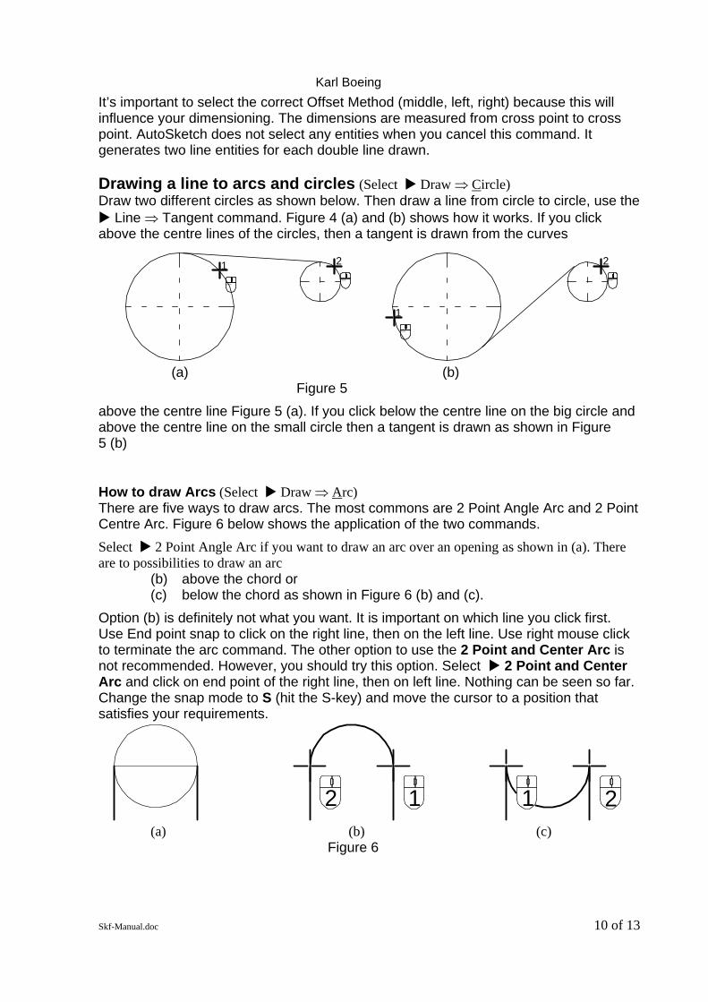
It’s important to select the correct Offset Method (middle, left, right) because this will influence your dimensioning. The dimensions are measured from cross point to cross point. AutoSketch does not select any entities when you cancel this command. It generates two line entities for each double line drawn. Drawing a line to arcs and circles (Select Draw ⇒ Circle) Draw two different circles as shown below. Then draw a line from circle to circle, use the
Line ⇒ Tangent command. Figure 4 (a) and (b) shows how it works. If you click above the centre lines of the circles, then a tangent is drawn from the curves
(a) (b) Figure 5 above the centre line Figure 5 (a). If you click below the centre line on the big circle and above the centre line on the small circle then a tangent is drawn as shown in Figure 5 (b) How to draw Arcs (Select Draw ⇒ Arc) There are five ways to draw arcs. The most commons are 2 Point Angle Arc and 2 Point Centre Arc. Figure 6 below shows the application of the two commands. Select 2 Point Angle Arc if you want to draw an arc over an opening as shown in (a). There are to possibilities to draw an arc
(b) above the chord or (c) below the chord as shown in Figure 6 (b) and (c).
Option (b) is definitely not what you want. It is important on which line you click first. Use End point snap to click on the right line, then on the left line. Use right mouse click to terminate the arc command. The other option to use the 2 Point and Center Arc is not recommended. However, you should try this option. Select 2 Point and Center Arc and click on end point of the right line, then on left line. Nothing can be seen so far. Change the snap mode to S (hit the S-key) and move the cursor to a position that satisfies your requirements.
12 1 2
(a) (b) (c) Figure 6

Karl Boeing
Skf-Manual.doc 11 of 13
The other arc commands are seldom used. However you should take a crack at those arc commands so that you know how they work.
Now you should have read enough and be able to start you first Drawing exercise.
Start Exercise 1. This exercise will include basic drawing settings, drawing different lines and shapes using different snap modes
Drawing Arcs, Circles, Polylines, Rectangles & Fitted Cuves
This portion of the tool bar shows all drawing commands for lines whether curved or straight.
In addition to lines you can draw Arcs, Circles, Polylines, Rectangles and Fitted Curves. The last icon is a Marker Point
Polyline A polyline is a series of lines with connected endpoint. They are treated as single entities.
A polyline is useful for drawing entities that have a fixed width, such as a wall in a floor plan. As you create each polyline segment, text boxes for the segment width and bulge appear on the edit bar. At this stage we will not use polyline because it is difficult to master, as a good understanding of polyline editing techniques is needed
Polygons You can draw a variety of different polygons as shown at the opposite toolbar. Polygons can be used to create
solid regions by using the solid fill command. We will scarcely use the polygons command. AutoSketch can explode polygons, polyline, as well as dimensions, symbols, to their component entities. This allows you to edit the individual components of an entity.
Trim command
Trimming is a way of refining and finishing a drawing. Trimming allows you to shorten and lengthen entities to meet at a specific point or break apart and divide entities. Unlike most of the Edit commands trim requires you to select a command before you specify the entities you want to trim.

Karl Boeing
Skf-Manual.doc 12 of 13
Trim the most often used command. You should now create a customised floating toolbar with the most used trim commands
Customised toolbar You can create and edit your own toolbars. Toolbars are automatically saved to disk when you create or modify them.
Each toolbar is made up of toolsets. Only one button from each toolset is visible in the toolbar at a time. If you click and hold the pointer (small triangle at lower right corner) on that button (see arrow), the rest of the buttons in the toolset appear.
1 On the View menu, click Toolbars, or right-click a toolbar, 2 Click New. The New Toolbar dialog box appears. 3 Enter the name that you want in this case ⇒ trim. 4 Do not enter a filename in the File text box. 5 The customise toolbar pop-up menu appears. In the Commands list, select a trim command.
(scroll down the slide bar until you see trim.) 6 Click the following buttons and them drag it to the Sets window and position (1-trim channel,
2-trim corner, 3-trim edge, 4-trim divide). 7 Click Close and you will see the trim floating toolbar on the screen. You can drag the bar
close to any trimming operation on your drawing.
The toolbar can be modified easily. You will modify this toolbar later by adding additional drawing tools to it.
Trim Commands You will do a lot of trimming. It’s important that you get familiar with these commands. The bold titles of the trim commands as shown below will be used very frequently. Corner Bevel Break Divide Join Union Difference Round Edge Channel Subdivide Alcove Intersection Trim Corner
Draw two lines (Figure 7 (a) and select
Trim Corner command. Click on line 1 and line 2 and the two lines will meet at the intersection as shown in Figure 7 (b)
(a) (b) Figure 7
21
line
1 line 2

Karl Boeing
Skf-Manual.doc 13 of 13
Chan
nel
Chan
nel
Chan
nel
Fina
l res
ult
12
3
4
Trim Edge Draw again two lines (Figure 8 (a) and select Trim Edge command. Click on line 1 and then on line 2 and line 2 will extent to line 1 as shown in Figure 8 (b)
(a) (b) Figure 8 Trim Channel Draw two double lines perpendicular to each other. Then select Trim Channel command. Click on line 1 and 2 as indicated in Figure 9 a) and a channel will be shown as dashed lines. Click on the line in the channel as shown in Figure 9 b). Make sure the circle cursor doesn’t touch the vertical lines otherwise the final result looks not as shown in Figure 9 c). a) b) c)
Figure 9 Using Symbol library On the Draw menu, click Symbol,
There is an easy way to create your own symbol. If you have drawn an element that you will it often use then create a symbol of it. Make sure you select all entities of the component first Go to the menu bar and select Draw, ⇒Symbols, ⇒Create the a window pops up Enter the symbol name and then click Save in Library (Browse to select a library) Click on next and if you want enter the default AutoField values (this is optional) Click next and remember to enter the basepoint after you click Finish.
21
line
1
line 2