Baseline Design Summary - Institute for Basic Science · Sun Kee Kim1, Yong Kyun Kim1, Young Jin...
206
Baseline Design Summary August, 2012 Rare Isotope Science Project
Transcript of Baseline Design Summary - Institute for Basic Science · Sun Kee Kim1, Yong Kyun Kim1, Young Jin...

Baseline Design Summary
August, 2012
Rare Isotope Science Project

2
List of Contributors
Jung Keun Ahn
2, Dong Hyun An
3, Kwang-yun Baek
2, Seung Won Baek
4, Jung-Bae Bahng
5, Sang-in Bak
29,
Dae-sik Chang28
, Byunggu Cheon21
, Myung-Ki Cheoun6, Dong-hyun Cho
8, Hee-Suk Cho
2, Bong Hyuk Choi
1,
Chang-il, Choi39
, Chul Jin Choi1, Eun-mi Choi
42, Han-woo Choi
31, Hyo-jung Choi
29, Kwang-Yong Choi
7, Min
Sik Choi46
, Seonho Choi9, Su Yong Choi
8, Tae-Keun Choi
26, Yeon Suk Choi
23, Hyun Tai Chung
9, Kie Hyung
Chung36
, Yeon Sei Chung1, Khalid M.M.Gad
29, Eun Ja Ha
6, Bo-young Han
28, Jae Eun Han
1, Jaemin Han
28,
Byungsik Hong8, In Seok Hong
1, Wan Hong
31, In-ho Huh
29, Min Sup Hur
42, Churl-kew Hwang
1, Ji-Gwang
Hwang5, Sanghoon Hwang
5, Won Joo Hwang
1, Chang Ho Hyun
10, Doh-Yun Jang
28, Jaeho Jang
13, Si-Won
Jang5, Zeehoon Jang
24, Dong O Jeon
1, Doo Jeong
29, Jae Min Jeong
11, Seung Ho Jeong
28, Sun-Chan Jeong
37,
Genie Jhang8, Kwang-ho Jo
41, Jong Dae Joo
1, Mi Joung Joung
1, Hoe Chun Jung
1, Yacine Kadi
29, Byoung Hwi
Kang1, Jeongsoo Kang
21, Keon Wook Kang
11, Sang Mook Kang
21, A-ram Kim
9, Byoung Chul Kim
18, Do
Gyun Kim1, Do-yoon Kim
29, Dong-Eon Kim
16, Dong Lak Kim
23, Dong Uk Kim
36, Eun-Joo Kim
14, Eun-San
Kim5, Geun Beom Kim
3, Gi Dong Kim
1, Hee-kyung Kim
48, Hong joo Kim
5, Hye Jin Kim
5, Hyun-Chul Kim
34,
Hyung Jin Kim1, In Gyu Kim
28, Jae Cheon Kim
1, Jong Tae Kim
29, Jong Won Kim
1, Joon-kon Kim
49, Kyung Il
Kim1, Mi Jung Kim
1, Myeongjin Kim
1, Sang-ho Kim
45, Sang-hoon Kim
47, Seo-hee Kim
29, Seong Jun Kim
1,
Sun Kee Kim1, Yong Kyun Kim
1, Young Jin Kim
1, Young Kwon Kim
1, Yeong-sun Kim
29, Youngman Kim
1,
Byeong Rok Ko8, Jin-a Ko
29, Seung Kook Koh
36, Jeong-Won Kwak
15, Taeg-yong Kwon
18, Young Kwan
Kwon1, Byeong-no Lee
28, Chang-Hwan Lee
2, Cheol-Woo Lee
28, Chi-hwan Lee
44, Chun Sik Lee
7, Hee-Jung
Lee20
, Hee-Seock Lee16
, Hoseong Lee18
, Hyo-Sang Lee2, Hyun Su Lee
17, Jaeyu Lee
13, Jeong Han Lee
1, Ju
Hahn Lee1, Kang Ok Lee
36, Kang-Seog Lee
27, Kwang-won Lee
28, Kyong Sei Lee
8, Sang-duk Lee
29, Seok
Kwan Lee46
, Seung kyu Lee21
, Su Houng Lee43
, Young-Ouk Lee28
, Young Sung Lee20
, Gwon Lim28
, Satarov
Matlabjon11
, Chang-Bum Moon19
, Jun-Young Moon7, Shinwoo Nam
1, Soon-Kwon Nam
32, Won Namkung
16,
Bong Hoon Oh13
, Byung-Hoon Oh28
, Jin-hwan Oh29
, Yongseok Oh5, Byung-yoon Park
35, Gunn Tae Park
1,
Jin-a Park29
, Jin Yong Park2, Junesic Park
21, Ki Hyun Park
13, Se-hwan Park
28, Sung Jong Park
1, Sung-Ho
Park9, Tae-sun Park
29, Wooyoon Park
20, Yung-ho Park
1, Chung-Yeol Ryu
21, Min-Sang Ryu
25, Chang Seok
Seo1, Hee Jeong Seo
36, Ik Jae Shin
1, Jae-won Shin
29, SeungWook Shin
29, Kwang-souk Sim
8, Woon-Young
So38
, Chang Wook Son40
, Jae Bum Son21
, Ho-seung Song29
, Hye-jin Song20
, Jong Sog Song1, Tae-Yung
Song28
, Byung Jin Suh22
, Zhou Tong29
, Kyoungho Tshoo1, Takuya Tsukioka
1, Eun Il Won
8, Mi Sook Won
23,
Hyung Joo Woo1, Ghil-Seok Yang
5, Haeryong Yang
16, Youngoo Yang
29, Sung-Joon Ye
9, Yeong-Heum Yeon
29,
Won Ju Yi30
, In-Kwon Yoo2, Jaegwon Yoo
28, Seong-Yeon Yoo
35, Jin Woo Yoon
1, Moohyun Yoon
13, Sato
Yoshiteru11
, Byung-Geel Yu33
, Dai-Hyuk Yu18
, and Chong Cheoul Yun1
1Institute for Basic Science, Daejeon 305-811, Korea
2Pusan National University, Busan 609-735, Korea
3Korea Institute of Radiological & Medical Sciences, Seoul 139-909, Korea
4Korea Institute for Advanced Study, Seoul 130-722, Korea
5Kyungpook National University, Daegu 702-701, Korea
6Soongsil University, Seoul 156-743, Korea
7Chung-Ang University, Seoul 156-756, Korea
8Korea University, Seoul 136-701, Korea
9Seoul National University, Seoul 110-799, Korea
10Daegu University, Gyeongsan 712-714, Korea
11Seoul National University, Seoul 151-742, Korea
12Advanced Photonics Research Institute, Gwangju 500-712, Korea
13Pohang University of Science and Technology, Pohang 790-784, Korea
14Chonbuk National University, Jeonju 561-756, Korea
15ASAN Medical Center, Seoul 138-736, Korea
16Pohang Accelerator Laboratory, Pohang 790-784, Korea
17Ewha Womans University, Seoul 120-750, Korea
18Korea Research Institute of Standards and Science, Daejeon 305-340, Korea
19Hoseo University, Cheonam 330-713, Korea

3
20Chungbuk National University, Cheongju 361-763, Korea
21Hanyang University, Seoul 133-791, Korea
22Catholic University, Seoul 110-758, Korea
23Korea Basic Science Institute, Daejeon 305-806, Korea
24Kookmin University, Seoul 136-702, Korea
25University of Seoul, Seoul 130-743, Korea
26Yonsei University, Wonju 220-710, Korea
27Chonnam National University, GwangJu 500-757, Korea
28Korea Atomic Energy Research Institute, Daejeon 305-353, Korea
29Sungkyunkwan University, Suwon 440-746, Korea
30Plasma & Energy Technology Corp. ,Seoungnam 464-120, Korea
31Korea Institute of Geoscience and Mineral Resources, Daejeon 305-350, Korea
32Kangwon National University, Chunchon 200-801, Korea
33Korea Aerospace University, Koyang 412-791, Korea
34Inha University, Incheon 402-751, Korea
35Chungnam National University, Daejeon 305-764, Korea
36Korea Accelerator and Plasma Research Association, Cheorwon 269-843, Korea
37High Energy Accelerator Research Organization, Tsukuba, Ibaraki-305-0801, Japan
38Kangwon National University, Samcheok 245-905, Korea
39Korea Institute of Nuclear Safety, Daejeon 305-338, Korea
40PEMTRON, Seoul 153-704, Korea
41Korea Institute of Nonproliferation and Control, Daejeon 305-348, Korea
42Ulsan National Institute of Science and Technology, Ulsan 689-798, Korea
43Yonsei University, Seoul 120-749, Korea
44Uiduk University, Seoul 120-749, Korea
45Oak Ridge National Laboratory, USA
46Dankook University, Yongin 448-701, Korea
47Argonne National Laboratory, USA
48SAMSUNG DISPLAY, Asan 336-840, Korea
49Korea Institute of Science and Technology, Seoul 136-791, Korea
Acknowledgements We thank authors of the Conceptual Design Report of Korea Rare Isotope Accelerator. Many parts of this
work were based on the result of the report. This work was supported by the Rare Isotope Science Project
funded by the Ministry of Education, Science and Technology (MEST) and National Research Foundation
(NRF) of KOREA (2011-0032011).

4
Table of Contents
Chapter I. Project Overview 5
I.1 Science goals and beam requirements 7
I.2 Concepts of Accelerators 12
Chapter II Rare Isotope Science 15
II.1 Nuclear astrophysics 17
II.2 Nuclear Matter 20
II.3 Nuclear structure 22
II.4 Study of Fundamental Symmetry 24
II.5 Nuclear theory 28
II.6 Medical and Bio Science 30
II.7 Material Science 32
II.8 Neutron Science 34
II.9 Atomic trap for rare isotope science 37
Chapter III Accelerators 39
III.1 Driver Linac 39
III.2. In-Flight Fragment system 118
III.3 Cyclotron 132
III.4 ISOL system 137
III.5 ISOL Post Accelerator 159
5
Chapter IV Experimental Apparatus 165
IV.1 KRS (Korea Recoil spectrometer) 165
IV.2 LAMPS (Large Acceptance Multi-Purpose Spectrometer) 167
IV.3 Separator for SHE (Super Heavy Element) 170
IV.4 High Resolution Spectrometer and ZeroDegree Spectrometer 171
IV.5 Neutron science 174
IV.6. Material Science 176
IV.7 Ion trap and Laser spectroscopy 179
IV.8 Medical/Bio Science 182
IV.9 Elemental Particle Physics 183
Chapter V Conventional Facilities 187
V.1 Site 187
V.2 Facilities 188
V.3 Cryogenic System 192
V.4 Electric Power System 196
V.5 Radiation Safety 198
Chapter VI Organization 201
Chapter VII Costs and Schedule 204

6
Chapter I Project Overview
As the major research facility of the International Science Business Belt (ISBB) in Korea,
construction of the accelerator complex for the rare isotope science was approved by the
Korean government in 2009. The Conceptual Design Report written in February of 2011
was reviewed by the International Advisory Committee. The IAC appreciated the
soundness of science goals and the unique feature of having both ISOL and IF for the
various rare isotope productions. The committee agreed that the cost estimate was
reasonable after making a comparison with other similar projects. Also, the committee
pointed out that the time schedule was aggressive and stressed the importance of the
international cooperation. In November 2011, the Institute for Basic Science (IBS) was
established as the main institution of ISBB to host about 50 research centers and other
affiliated Institutes. In order to carry out the technical design and the construction of the
accelerator complex, the Rare Isotope Science Project (RISP) was established in December
2011, in the IBS. The project will be housed in the IBS affiliated “Accelerator Institute”
later, which will be operated independently of the IBS.
The accelerator complex will be located in “Sindong” area in the Northern part of
Daejeon City. The goal of the accelerator complex is to produce variety of stable and rare
isotopes to be used for researches in basic science and various applications. The complex
consists of a heavy ion linear accelerator as the driver, called as Driver Linac, for the IF
(In-flight Fragmentation) system, a proton cyclotron as the driver for the ISOL (Isotope
Separation On-Line) system and a post-accelerator for the ISOL system. The ISOL and the
IF systems will be operated separately and independently. In addition, the rare isotopes
produced in ISOL can be injected into the Driver Linac for accelerating the RI beam even
higher energies or for use in IF system to produce even more exotic rare isotopes. In the
future stage, the proton beam in the Driver Linac can be used for the ISOL system with
7
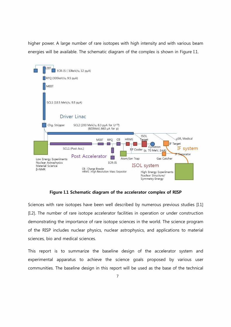
higher power. A large number of rare isotopes with high intensity and with various beam
energies will be available. The schematic diagram of the complex is shown in Figure I.1.
Figure I.1 Schematic diagram of the accelerator complex of RISP
Sciences with rare isotopes have been well described by numerous previous studies [I.1]
[I.2]. The number of rare isotope accelerator facilities in operation or under construction
demonstrating the importance of rare isotope sciences in the world. The science program
of the RISP includes nuclear physics, nuclear astrophysics, and applications to material
sciences, bio and medical sciences.
This report is to summarize the baseline design of the accelerator system and
experimental apparatus to achieve the science goals proposed by various user
communities. The baseline design in this report will be used as the base of the technical
8
design report. It should be noted that the given time limit permits only limited R&D and
we need to adapt the known technologies and experiences acquired by other accelerator
projects and laboratories in the world.
[Reference I]
[I.1] D. F. Geesaman, C. K. Gelbke, R. V. F. Janssens, and B. M. Sherrill, Ann. Rev. of Nucl.
And Part. Sci. 56, 53 (2006)
[I.2] Scientific Opportunities with a Rare-Isotope Facility in the United States, Rare
Isotope Science Assessment Committee, NRC, The national academies press (2007)
I.1 Science goals and beam requirements
The basic and applied science using the rare isotope (RI) beams is a challenging research.
In particular, the production of the RIs near the drip line and their properties are still
unexplored compared to those basic elements and proton- or neutron-deficient RIs due
to the difficulties of RI production.
Figure I.1-1 shows the high priority studies in the proton- or neutron-rich region on the
chart of nuclei by the axes of numbers of protons and neutrons. The RISP accelerator
facility has been conceptually designed to produce especially neutron-rich RI beams near
the drip line, and to study the basic and applied sciences with challenging ideas and
schemes.
By using low and high energy RI beams, the basic science, nuclear physics, astrophysics
and atomic physics will be researched. The programs include the study of nuclear
structure of very neutron rich nuclei near the drip line, the properties of exotic nuclei and
the equation of state (EoS) of nuclear matter, and the attempt to understand the origin
of the universe and the process of nucleosynthesis under the various stellar environments.

9
In addition, one of the aims of the RISP is to discover a new super-heavy element with
Z>116, which can be named as “Koreanium”.
For the applied science, finding new material, mutating the cell or DNA, constructing
nuclear data, and developing new medical heavy ion therapy will be fulfilled. The
material science with RI beams, whose scale is in femto(10-15) meter, will give us chance
to make new materials, to study their properties, and to see a dynamic image in the
nano(10-9) meter scale. For the medical and biological applications, there is a plan to
develop the advanced treatment technology by using energetic RI beams and to study
the mutation of DNA. A systematic nuclear data measurement using fast neutrons has
been planned for the future nuclear energy development and radioactive waste
transmutation research
In order to produce RI beams of high purity and high intensity near the proton- and
especially neutron- drip line, the two RI production methods[I.1.1] will be used: isotope
separation on-line (ISOL) and in-flight fragmentation (IFF).

10
Fig I.1.1 High priority researches on the chart of nuclei by axes of the numbers of
proton and neutron. The stable (solid black square), known (yellow region),
undiscovered (green and white region) nuclei are indicated in the region up to
neutron and proton drip lines (outermost black lines). The narrow vertical and
horizontal lines mean the nuclear magic numbers. The base figure is from [I.1.2].
The RISP facility can produce exotic proton- or neutron-rich RI beams and has a unique
operation mode that nobody has tried before. It will give us more opportunities close to
the region near the drip-line by using more exotic RI beams. Thus, the RISP accelerator
can be a highly valuable machine for nuclear and other basic sciences, and will bring lots
of opportunities for young scientists to see and learn about both scientific and industrial
effects.
The various kinds of RI beams of proton- and neutron-rich nuclei which are demanded
for research opportunities at RISP are summarized in table I.1.1. The required RI beams
are listed by the RISP user community with thorough consideration of perspective and
analysis of current research trends for research fields of RI science.
Table I.1.1 Selected RI beam requirements for RISP research opportunities
RI Beam species Energy Range Desired Intensities
[ particles / sec ] Research fields
80Ni, 76Fe, 132Sn, 144Xe > 100 A MeV > 109 Nuclear structure
80Ni, 76Fe, 132Sn, 144Xe 5-20 A MeV > 108 Nuclear Structure
15O, 14O < 10 A MeV
< 30 keV
> 1010-11
> 108
Nuclear
astrophysics
Material Science
26mAl 5-20 A MeV > 107-8 Nuclear
astrophysics
11
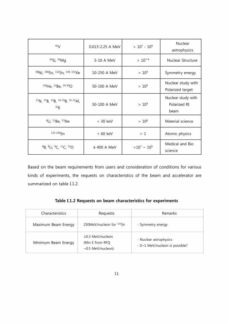
45V 0.613-2.25 A MeV > 107 - 109 Nuclear
astrophysics
39Si, 36Mg 5-10 A MeV > 107-9 Nuclear Structure
68Ni, 106Sn, 132Sn, 140, 142Xe 10-250 A MeV > 109 Symmetry energy
6,8He, 12Be, 24-30O 50-100 A MeV > 109 Nuclear study with
Polarized target
17N, 17B, 12B, 14-15B, 31-32Al,
34K 50-100 A MeV > 109
Nuclear study with
Polarized RI
beam
8Li, 11Be, 17Ne < 30 keV > 108 Material science
133-140Sn < 60 keV > 1 Atomic physics
8B, 8Li, 9C, 11C, 15O ≥ 400 A MeV >107 ~ 109 Medical and Bio
science
Based on the beam requirements from users and consideration of conditions for various
kinds of experiments, the requests on characteristics of the beam and accelerator are
summarized on table I.1.2.
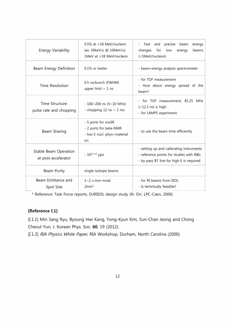
Table I.1.2 Requests on beam characteristics for experiments
Characteristics Requests Remarks
Maximum Beam Energy 250MeV/nucleon for 132Sn - Symmetry energy
Minimum Beam Energy
≤0.3 MeV/nucleon
(Min E from RFQ
~0.5 MeV/nucleon)
- Nuclear astrophysics
- 0~1 MeV/nucleon is possible?
12
Energy Variability
0.5% at <18 MeV/nucleon
(ex. 50keV/u @ 10MeV/u)
1MeV at >18 MeV/nucleon
- Fast and precise beam energy
changes for low energy beams
(<5MeV/nucleon)
Beam Energy Definition 0.1% or better - beam-energy analysis spectrometer
Time Resolution 0.5 ns/bunch (FWHM)
upper limit ~ 1 ns
- for TOF measurement
- How about energy spread of the
beam?
Time Structure:
pulse rate and chopping
- 100~200 ns (5~10 MHz)
- chopping 12 ns ~ 1 ms
- for TOF measurement, 81.25 MHz
(~12.3 ns) is high
- for LAMPS experiment
Beam Sharing
- 5 ports for muSR
- 2 ports for beta-NMR
- low E nucl. phys+material
sci.
- to use the beam time efficiently
Stable Beam Operation
at post-accelerator - 1011-12 pps
- setting up and calibrating instruments
- reference points for studies with RIBs
- by-pass BT line for high E is required
Beam Purity single-isotope beams
Beam Emittance and
Spot Size
1~2 mm-mrad
2mm2
- for RI beams from ISOL
- Is technically feasible?
* Reference: Task Force reports, EURISOL design study (N. Orr, LPC-Caen, 2006)
[Reference I.1]
[I.1.1] Min Sang Ryu, Byoung Hwi Kang, Yong-Kyun Kim, Sun-Chan Jeong and Chong
Cheoul Yun, J. Korean Phys. Soc. 60, 19 (2012).
[I.1.2] RIA Physics White Paper, RIA Workshop, Durham, North Carolina (2000)

13
I.2 Concepts of Accelerators
The accelerator complex is designed to become one of the world’s leading facilities in
rare isotope science. The rare isotopes can be produced either target spallation, fission in
the ISOL system or projectile fragmentation in the IF system. Two methods produce rare
isotopes of different characteristics, and thereby provide wider varieties of rare isotopes
than other facilities operating only one of the two methods. The science goals described
in the last section require high intensity RI beams with various beam energies. The
complex has three accelerators; two heavy ion linear accelerators, and one cyclotron. The
driver accelerator for IF system (Driver Linac) consists of two ECR ion sources, low energy
beam transport (LEBT), RFQ, medium energy beam transport (MEBT), low energy
superconducting linear accelerator, charge stripper and high energy superconducting
linear accelerator. At the end of the high energy linear accelerator, proton beams are
accelerated to 600 MeV and Uranium to 200 MeV/u. The beam current for the Uranium
beam is 8 pμA. The driver accelerator for the ISOL system is a proton cyclotron with the
beam energy of 70 MeV and beam current of 1 mA. The post accelerator is designed to
accelerate the rare isotopes produced in the ISOL system up to ~20 MeV/u. But the post
accelerator can provides the stable isotopes at the same energy with an additional ECR
ion source. Therefore, in principle, the post accelerator is a duplicate of driver accelerator
up to low energy linear accelerator. Beam specification and components for each
accelerator system are summarized in Table I.2.1.
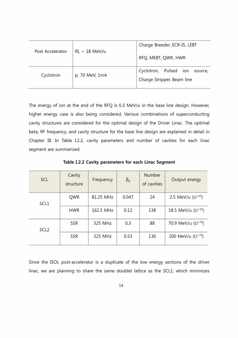
Table I.2.1 Beam specifications and main components for each accelerator system
Accelerator Beam specification Components
Driver Linac
p, 600 MeV,
U+78, 200 MeV, 8 pμA
ECR-IS, LEBT, RFQ, MEBT, QWR,
HWR, Charge Stripper, SSR1, SSR2
14
Post Accelerator RI, ~ 18 MeV/u
Charge Breeder, ECR-IS, LEBT
RFQ, MEBT, QWR, HWR
Cyclotron p, 70 MeV, 1mA Cyclotron, Pulsed ion source,
Charge Stripper, Beam line
The energy of ion at the end of the RFQ is 0.3 MeV/u in the base line design. However,
higher energy case is also being considered. Various combinations of superconducting
cavity structures are considered for the optimal design of the Driver Linac. The optimal
beta, RF frequency, and cavity structure for the base line design are explained in detail in
Chapter III. In Table I.2.2, cavity parameters and number of cavities for each linac
segment are summarized.
Table I.2.2 Cavity parameters for each Linac Segment
SCL Cavity
structure Frequency βg
Number
of cavities Output energy
SCL1
QWR 81.25 MHz 0.047 24 2.5 MeV/u (U+33)
HWR 162.5 MHz 0.12 138 18.5 MeV/u (U+33)
SCL2
SSR 325 MHz 0.3 88 70.9 MeV/u (U+79)
SSR 325 MHz 0.53 136 200 MeV/u (U+79)
Since the ISOL post-accelerator is a duplicate of the low energy sections of the driver
linac, we are planning to share the same doublet lattice as the SCL1, which minimizes

15
types of accelerator components and reduces cost and R&D efforts. Cavities of the same
types and betas will be used as well as the same type of cryomodules.

16
Chapter II Rare Isotope Science
A variety of basic and applied science can be studied with RI beams. Especially high
intensity and high purity RI beams near the drip lines can give us tremendous
opportunities to explore the entire universe from microscopic to macroscopic world. The
research subject is categorized into four science fields as follows.
Nuclear Science: Research programs in nuclear physics can be roughly divided into:
search for drip lines, investigation of shell gaps, study of deformed nuclei, study of
charge exchange reaction on various nuclei, study of single particle wave functions, study
of asymmetric nuclear matter, and investigation of breaking of fundamental symmetries.
The main issue of nuclear astrophysics is to understand key nuclear reactions that
synthesize the elements and are responsible for energy generation in stars with different
temperatures and densities. The Symmetry Energy in nuclei, which accounts for the
asymmetric nature of the strong interactions in nuclear medium, is one of main research
topics in nuclear physics program.
Nuclear data is a part of nuclear physics and a basic element in the research and
development of nuclear engineering. Research related to nuclear data is divided into two
categories: experimental measurement and theoretical research, such as the evaluation
and development of nuclear models. Experimental measurements can provide nuclear
data directly and be the basis of model evaluation and development at the same time.
Atomic & Molecular Science: Precise mass measurements enable the study of the fine
structure of the mass surface and clarification of discontinuities in order to extract
nuclear structure information from binding energies. Data far from the valley of β-
stability represent well-suited test cases for the predictive power of mass models. High-
precision measurements of masses, spins, and moments provide important ingredients

17
for reliable nuclear astrophysical calculations, and help us understand the composition of
matter in the universe in general.
Material Science: RI material science facilities at RISP involve the β-NMR, PAC, EC, and
μSR, and can be a part of the world-leading material research facility. New
semiconductor materials, spintronics, and superconducting phenomena could be studied
with the RISP RI material science facilities.
Medical & Bio Science: With RISP facility, we will find new ways to improve the effect of
heavy ion therapy by studying the physical methods, radio-resistant mechanism of
cancer cells to heavy ions, new targets and drugs, and normal tissue damage to heavy
ions. In the bioscience field, the RISP facility can provide the most current information on
the biological effects of heavy ion beams to be used in all biological fields, including
radiation biology, microbiology, cancer biology, and radiation oncology.
And the high priority research subjects are summarized in Table II.1.

18
Table II.1 High priority research subject at RISP
II.1 Nuclear astrophysics
The main purpose of nuclear astrophysics is to understand key nuclear reactions that
synthesize the elements and are responsible for energy generation in stars with different
temperatures and densities. Because a lot of thermonuclear reactions in explosive stellar
sites involve radioactive isotopes, the proposed RISP facility is expected to play an
important role in nuclear astrophysics. Various experiments with RI beams by the RISP
accelerator have been discussed and proposed to further understanding of element
formation following fusion reactions and neutron captures inside and on the surfaces of
stars. Important nucleosynthetic processes in various stellar sites are hydrogen-helium

19
burning thermonuclear reactions, CNO cycle, HCNO cycle, rapid proton capture reactions
(rp-process), slow neutron capture reactions (s-process), and rapid neutron capture
reactions (r-process).
We give special emphasis to measuring the reaction rates that create and destroy long-
lived nuclei such as 22Al, 26Al, and 44Ti that are targets for gamma-ray astronomy. We also
focus on the r-process that creates neutron-rich nuclei with neutron magic numbers of
82 and 126.
We expect to lead the way to solving key issues in astrophysics, such as the structure
and evolution of stars (neutron stars, pulsars, and supernovae), the generation of energy
in stars, the synthesis of the heavy elements in stars, and the structure and formation of
the solar system and our galaxy.
The accurate reaction rates for astrophysical nuclear reactions are critical inputs for stellar
models. We have experiences for determination of reaction rates with RI beam via
indirect methods like elastic resonant scattering [II.1.1.1]. But the best way to decide
reaction rates is the direct measurement of reaction. We expect that cross sections for
important nuclear reactions such as proton- or alpha-capture reactions can be measured
directly with intense RI beam and recoil spectrometer system at the RISP. These results
are going to be essential information for better understanding for nucleosynthesis and
energy generation in explosive hydrogen burning environments such as novae and X-ray
bursts. One of main research topics is the direct measurement of reaction rate for
15O()19Ne reaction. In the rp-process under a condition of novae, the CNO material
would be transmuted to heavier elements. The first step of the process is considered to
be 15O()19Ne reaction – break-out reaction from CNO cycle to rp-process. For the
direct measurement of 15O()19Ne reaction, recoil separator with high background
suppression and high intense 15O RI beams (>1011 pps) are essential. We expect that the

20
KRS (Korea recoil spectrometer) and 70 kW ISOL system at the RISP should fulfill
experimental requirements.
Investigations of the abundances of the elements found on Earth and in meteorites are
essential to understanding the production of stars as well as the formation of the solar
system. Measurements of the cross section through the nuclear reactions are important
to this study, and RIBs are especially essential for searching the unexplored territory
(Terra Incognita).
Major research topics which will be performed with RI beams at the RISP facility are
summarized as follows:
The production and extinction of galactic gamma-ray line
Abundance of important elements by the CNO cycle and the formation of the solar
system
Nucleosynthesis of proton rich nuclides by rapid proton capture process (rp-process)
Reaction rates of astrophysically important proton and alpha capture reactions
Determination of the abundances of stable nuclides and around isotopes by the slow
neutron capture process (s-process), and neutron rich nuclides by the rapid neutron
capture process (r-process)
[Reference II.1.1]
[II.1.1.1] H. S. Jung, Y. K. Kwon, C. C. Yun, Y. K. Kim et al., Phys. Rev. C 85, 045802 (2012).

21
II.2 Nuclear Matter
There are more neutrons than protons in heavy stable nuclei. The semi-empirical mass
formula successfully explains the masses of stable nuclei from light ones to heavy ones,
but the structure of neutron-rich nuclei beyond the limit of stability is not yet fully
understood. Symmetry energy is the energy that requires converting a proton to a
neutron inside a nucleus. Therefore, understanding the nature of symmetry energy will
offer clues to fundamental questions about the asymmetric constitution of nucleons in
heavy nuclei, isospin asymmetry in nucleon-nucleon interactions, their modifications in a
nuclear medium, etc. In addition, recent research shows that symmetry energy plays a
critical role in the properties of a neutron star, such as its cooling rate, mass, and radius.
The goal of the proposed investigation is to understand the nature of symmetry energy
in nuclei and in nuclear matter with nuclei from stable ones to those far from the
stability valley, and to apply our knowledge to related phenomena from a microscopic
scale to stellar objects.
Symmetry energy is the strong interaction caused by the difference in the number of the
neutron and the proton. Figure II.1.2.1 shows the energy per nucleon in nuclear matter as
a function of density. For the normal nuclei in which the number of the neutron is
approximately equal to that of the proton, the volume term of the binding energy is
represented by the lowest thick solid line. However, if a nucleus is composed of only
neutrons, the symmetry energy has to be added to the binding energy, and as a result
the binding energy shown by the black solid line predicts an unstable state. As the mass
number increases, the ratio of the neutron number to the proton one, N/Z deviates from
1 substantially. Therefore, it is important to understand the behavior of symmetry energy
to figure out the origin of N/Z >1 in heavy nuclei.
For science, the RISP facility will provide high-intensity RI beams with unprecedented
neutron-to-proton ratios. The operation of the RISP at high energies will provide an ideal

22
environment for studying the stability of nuclear matter with extreme neutron-to-proton
ratios. The stability of the neutron-rich matter depends directly on the equation of state
of the isospin asymmetric energy term, which is determined by the isoscalar and
isovector potentials. However, our knowledge about these potentials is limited, especially
at high densities. In a dense medium, the mass modification of hadrons and the three-
body interactions can also alter the density dependence of the equation of state for the
isospin asymmetric energy term. RISP will enable us to describe the quantitative
distinction of various sources for the modification of the isospin-dependent equation of
state by measuring the energy (or density) dependence of several observables.
Fig II.1.2.1 Theoretical model of nuclear symmetry energy. Normal nuclear density =
0.16 fm-3. [II.1.2.1]
[Reference II.1.2]
[II.1.2.1] F. de Jong and H. Lenske, Phys. Rev. C 57, 3099 (1998); F. Hofman, C. M. Keil and
H. Lenske, Phys. Rev. C 64, 034314 (2001)

23
II.3 Nuclear structure
Research programs in nuclear physics can be roughly divided into 7 subjects: search for
drip-lines, investigation of shell gaps, study of deformed nuclei, study of charge
exchange reaction on various nuclei, study of single particle wave functions, study of
asymmetric nuclear matter, and investigation of breaking of fundamental symmetries.
It is highly like that the search for new isotopes will be the first experiment once the
facility is completed. During this process, it is also possible to find new isomer states by
detecting delayed gamma rays. The new isotopes or isomers near the drip-lines require
more detailed investigation of their properties. Interesting phenomena include halo
nuclei, two-neutron (or two-proton) emitters, beta-delayed neutron emission, and
neutron skins.
Information on the properties of various nuclei near the neutron magic number, N~126,
is critical for new isotopes search, and for changes in nuclear shell structure of very
neutron rich nuclei. And also because nuclei along the N~126 are waiting points of r-
process, basic properties such as masses and -decay half-lives are important for
understanding nucleo-synthesis under the extreme stellar environments. Recently
measured half-lives of these nuclides near N~126 are found to be very different from the
previous theoretical values. These results show clearly that theoretical predictions on the
basic physical parameters, mass and half-life, about unknown nuclides have limitations.
As a primary goal, we focus on the measurements of their half-lives. We also pay
attention to the production methods for super neutron rich isotopes by the secondary
nuclear reactions using the neutron rich RI beams as building up online separation
methods.
The modification of shell gaps with increasing neutron numbers is another important
research program for neutron-rich isotopes. It has been discovered that the conventional

24
magic numbers (or shell gaps) are modified as the number of neutrons increases toward
the drip-line. This requires precise mass measurement and measurement of excitation
energy to the first 2+ states.
While stable nuclei are spherical, neutron-rich isotopes can have deformation even at
their ground states. The study of the degree of deformation as a function of the number
of neutrons is another interesting topic. Deformed nuclei produced in the reaction often
carry high angular momentum, and will be a unique laboratory to study the interplay
between collective and single-particle motion.
Charge-exchange reactions on nuclei are another versatile method to measure Gamow-
Teller strength compared to the usual beta-decay study. While measurement of the beta-
decay is limited with Q value, charge exchange reactions do not have such a limit.
Charge-exchange reactions will play another important role in studying the properties of
various unstable isotopes produced by the facility.
Transfer reactions or knock-out reactions can study wave functions of a single particle or
correlated pair of nucleons. With the capability to adjust the number of neutrons, transfer
and knock-out reactions can study the evolution of these wave functions over a wide
range of isotopes.
Compared to stable isotopes, for which the numbers of protons and neutrons are more
or less symmetric, these neutron-rich isotopes have large asymmetry between these two
nucleons. In nature, such asymmetric nuclear matter can be found in neutron stars, for
example. Thus, neutron-rich isotopes can be a unique access point for asymmetric
nuclear matter, providing important clues to understanding neutron stars.
25
II.4 Study of Fundamental Symmetry
If the same equations of motion describe the system after the transformation of some of
the variables, then the transformation is said to be symmetry. Note that the
transformation may change the solution to the equations of motion, because we have
different initial conditions. However, a transformation is asymmetric only if a new set of
equations are required to describe the evolution of the system, and not just a change in
the initial conditions. The symmetry is said to be violated when the transformation does
not reserve the equations of motion for the system of interest. Familiar symmetries
include:
1. Proper symmetries (can be carried out continuously in infinitesimal steps)
Spatial translation
Rotation
2. Improper or discrete symmetries (cannot be built up from infinitesimal steps; they are
all or nothing)
Parity (P)
Time reversal (T)
Change conjugation (C)
Over the past fifty years, there have been considerable works done studying violations of
C, P and T.
CP violation has been well established that parity (P) symmetry is violated in weak
interactions, and the experiment of Christenson, Cronin, Fitch, and Tuylay in 1964
demonstrated that the combined charge-parity (CP) symmetry is violated in the decay of
neutral kaons.
26
T violation. Recently, the CPLEAR collaboration at CERN has shown direct time reversal
invariance (T) violation, again in the neutral kaon system.
This had long been expected, because of the powerful CPT theorem. This theorem
requires that acting on any state with all three operations C, P, and T must return the
original state. It has been rigorously proven for any local theory which satisfies Lorentz
invariance. Thus a CP violation should be synonymous with a T, or time reversal, violation.
Numerous searches have been made for either CP or T violation in other systems. So far,
the baryon asymmetry of the universe is the only other evidence of such a violation, and
that evidence is rather hard to quantify. However, the continuing experiments have
succeeded in pushing down the upper limits on time reversal violating effects by many
orders of magnitude in the past four decades.
Clearly an impressive amount of effort has gone into observing CP violation in the
neutral kaon system. However, many proposed CP violating processes, including the
baryon asymmetry of the universe, are not flavor changing and so would have to arise
from a separate mechanism. Electric Dipole Moment (EDM) measurements are one of the
best ways to set limits on many of the mechanisms that theorists have proposed.
A measurement of EDM is important because an EDM violates parity and time reversal.
Take a particle with some net spin, and imagine that it also has a separation of charge.
The Wigner-Eckhart theorem requires that the charge separation must lie along the spin
axis. Under a time reversal operation, the orientation of charge remains the same, but
the direction of spin changes: thus time reversal is violated. The case for parity is
completely analogous.
An atomic EDM would either arise from an intrinsic fermion EDM or the elementary
particle interactions among the atom's constituents. The Standard Model and its various
extensions have different CP violating parameters that could lead to an EDM. Searches

27
that can set new limits on T violation thus provide much needed evidence to determine
which of the theories are physically permissible.
Some specific isotopes can amplify the effect of broken fundamental symmetry, such as
the electric dipole moment, and can be used to test more easily the fundamental
symmetry of the universe. The impact of such a finding would be enormous, and would
require new theory to replace the current Standard Model. If it is successful, experiments
on these rare isotopes can produce results that cannot be obtained with large
accelerators, such as LHC at CERN.
As discussed above, an EDM cannot exist unless both P and T invariance are violated.
This can be easily seen from the non-relativistic Hamiltonian for the interaction of an
EDM d with an electric field E, which is HEDMNR = −𝐝 ∙ 𝐄 . Now, a fundamental particle or
nucleus in a non-degenerate state, the spin angular momentum J is the only 3-
dimensional vector available to define a direction of the system. Thus, d must be
collinear with J, and
HEDMNR = −𝐝 ∙ 𝐄 = −d
𝐉
J∙ 𝐄.
But E is a T-even polar vector while J is a T-odd axial vector, and therefore HEDMNR is odd
under P and T transformations. The identical conclusion is of course true for the
relativistic generation of HEDMNR [II.1.4.1], with subtle minor changes due to a relativistic
effect.
So far, no EDM has been observed, and it is obvious from the present experimental
upper limits, that EDMs predicted by Standard Model must be extremely small. For
example, the upper limit on the electron EDM |de| is 10.5x10⁻²⁸ e cm [II.1.4.2].
Nevertheless, EDMs may be non-zero, because P and T are in fact violated in nature.
Parity non-conservation as well as the violation of charge conjugation invariance occurs
28
in the weak interaction. Furthermore, combined CP violation is observed in neural K
meson and B meson decays [II.1.4-3]. If we assume CPT invariance, for which we have
very strong confidence, then this CP violation is equivalent to T violation. Thus the weak
interaction and the mechanism or mechanisms causing CP violation could act jointly to
generate EDMs by P, T-odd radiative correction to the P, C, T conserving electromagnetic
interaction with the Standard Model of particle physics phenomenology.
However, there are good reasons to think that additional mechanisms exist for CP
violation. It is generally accepted that if the universe initially was symmetric in baryon-
antibaryon number, the presently observed baryon-antibaryon asymmetry could not have
developed without a much larger CP violation than is predicted by the Standard Model
[II.1.4-4]. Furthermore, in many theories that attempt to go beyond Standard Model,
predicted EDMs are relatively large, for example, in various supersymmetric theories,
many new hypothetical particles and coupling appear, and along with them exist new CP
violating phases. Thus in many such models the electron and neutron EDMs already
appear at the one-loop level, and as a result prediction of electron and neutron EDMs
are closed to present experimental limits. Thus discovery of an EDM by practical
experimental methods is a real possibility within the foreseeable future, and such a
discovery would provide definite evidence for physics beyond the standard model.
Together with EDM, lepton number conservation is another prediction that is strongly
supported by Standard Model. In particular, search for lepton violation in decays such
as μ → eγ , μA → eA, μ → eee has been carried out extensively over past years. The
prediction from Standard Model branching fraction of μ → eγ, for example is less than
10-54, that is approximately 30 order of magnitude smaller than present experimental
sensitivity [II.1.4-5]. This translates into the fact that there are plenty of rooms for new
physics beyond Standard Model can enhance (if theoretically possible) the effect so that
experimental search for new physics potential is extremely rich.
29
[Reference II.4]
[II.1.4.1] E. D. Commins, Journal of Phy. Soc. Of Japan 76 111010 (2007)
[II.1.4.2] J. J. Hudson, et. Al., Nature, 473, 493 (2011)
[II.1.4.3] D. Kirkby and Y. Nir, J Physics G 33, 1 (2006).
[II1.4.4] See, for example, W. Bernreuther: in CP violation in Particle, Nuclear and
Astrophysics, et. M. Beyer (Springer Berlin, 2002) p. 237.
[II1.4.5] J. Adam, et al., Phys. Rev. Lett. 107, 171801 (2011)
II.5 Nuclear theory
Our goal is basically to understand the origin of matter created through nucleosynthesis
that includes all reactions such as the capture by neutrons and protons, the scattering by
leptons, the fusions by finite nuclei and so on. To describe them, we divide our works
into five parts.
First, the study of exotic nuclear structure includes the structure of all spherical and
deformed nuclei. To do that, our group has developed deformed quasi-particle random
phase approximation (DQRPA) model to describe the structure of deformed nuclei. The
unstable nucleus is usually deformed so that we use Nilsson basis to calculate deformed
nuclei. In this model, when deformation parameter is equal to zero, it means that the
nucleus is spherical shape. Thus, we can calculate all spherical and deformed nuclei by
using DQRPA model.
Thermal nuclear reactions and nuclear processes in the cosmos are for nuclear reactions
by neutrons and protons. In nucleosynthesis, main processes are slow neutron capture(s-
30
process) and rapid neutron capture (r-process). Since the reactions in s- or r-process are
capture reactions by a neutron, the situation is involved in nuclear structure of finite
nuclei with an exited neutron which can be described by DQRPA model. In addition, the
nucleus emits gamma ray when the exited neutron goes down into ground state. Thus
this calculation includes both processes; one is nuclear structure by DQRPA and the other
is gamma ray emission. Proton process and thermal nuclear reactions are very sensitive
on nuclear density and temperature. In the environment with high density and high
temperature, the capture reaction by proton is possible and new channels can be opened.
The model for proton capture reaction is similar with neutron capture reaction except for
Coulomb potential. Thus DQRPA and gamma ray emission are employed to calculate
proton process and thermal nuclear reactions.
The study for the sites for nuclear processes is to describe the environment that
nucleosynthesis occurs. For instance, when nuclear reactions take place in BBN at early
universe, the universe expands with time. Thus, nucleosynthesis is combined with
hydrodynamics which describes the expansion of the universe. The situation is similar to
nucleosynthesis inside stars because nuclear reactions depend on density and
temperature. One of issues in nuclear astrophysics is to describe the process from
supernovae explosion to neutron star. Theorists group has studied the infinite matter and
the structure of neutron star by using relativistic mean field models and wants to expand
our models.
Finally, the study of nuclear abundances in the universe is for nuclear reactions with
leptons, especially neutrinos. In the simulation of nucleosynthesis, s-, r- and rp-processes
are included but the results still show some incompatibility as compared with observed
data. As the solution, neutrino process is proposed in some reactions. When a
supernovae explodes, huge amount of neutrinos are emitted so that neutrinos can affect
nucleosynthesis although the cross section by neutrinos is very small. We thus have
31
studied the nuclear scattering by neutrinos, considering charged and neutral currents. We
also expect that this work can give the explanation of nuclear abundance in the universe.
Major research topics can be summarized as follows:
The study of exotic nuclear structure
Thermal nuclear reactions in the cosmos
Nuclear processes in the cosmos (slow and fast processes and proton processes)
Research of cosmological sites for nuclear processes
Study of nuclear abundances in the universe
II.6 Medical and Bio Science
Due to higher biologic effects compared with x- or gamma-rays, heavy ion beams can be
used to treat intractable cancers and to study life science, such as the change of genes,
proteins, cells or organs to heavy ions [II.1.6.1].
The primary rationale for radiation therapy (RT) with charged particles is the sharp
increase of dose in a well-defined depth (Bragg peak) and the rapid dose falloff beyond
that maximum [II.1.6.2]. The ratio of Bragg peak dose to entrance region dose is larger
for heavy ions than for protons. Therefore, heavy ions offer an improved dose
conformation compared with photon and proton RT, with better sparing of normal tissue
structures close to the target. In addition, heavy ions exhibit a strong increase of the LET
in the Bragg peak compared with the entrance region. Equal doses of different types of
radiation do not produce equal biological effects. The key difference resides in the
pattern of energy deposition at the microscopic level. The relative biological effectiveness
32
of heavy ions is several times greater than that of photons. Heavy ions are less affected
by oxygen status than photons [II.1.6-3], and are able to kill cells nearly equally well in all
phases of the cell cycle. As the linear energy transfer increases, the relative biological
effectiveness also increases. As the oxygen enhancement ratio falls, the relative biological
effectiveness of radiation rises. With the RISP facility, we will find new ways to improve
the effect of heavy ion therapy by studying the physical methods, radioresistant
mechanism of cancer cells to heavy ions, new targets and drugs and normal tissue
damage to heavy ions.
The research goal in the bioscience field at the RISP facility is to provide the most
current information on the biological effects of heavy ion beams to be used in all
biological fields, including radiation biology, microbiology, cancer biology, and radiation
oncology. Information about genomic and proteomic responses to heavy ion beams can
reveal the subsequent biochemical and physiological function in living cells [II.1.6.4]. This
may have a major impact on advances in cellular and molecular radiation biology, as X-
ray resulted in the discovery of the double helix model of DNA structure [II.1.6.5]. In
conclusion, the purpose of biological study using heavy ion beams is to increase our
knowledge of the mechanism of heavy ion induced changes on cellular and molecular
levels, and to conjugate a variety of biological fields. The goals of biological research
include the study of the following:
Linear energy transfer, cellular heavy ion damage, and its modification
Genomic and proteomic response to heavy ion beams and identification of their
biological functions
Heavy ion induced damage, cell death, and repair
Heavy ion induced cellular senescence and its mechanism

33
Epigenetic changes induced by heavy ion beams, and their biological importance
Heavy ion beam-induced mutation, variant microbes and plants, and their applications
Basic cancer biology using heavy ion beams.
[Reference II.1.6]
[II.1.6.1] M. Durante, J. S. Loeffler, Nat Rev Clin Oncol 7, 37 (Jan, 2010).
[II.1.6.2] E. Fokas, G. Kraft, H. An, R. Engenhart-Cabillic, Biochim Biophys Acta 1796, 216
(2009)
[II.1.6.3] O. Jakel, C. P. Karger, J. Debus, Med Phys 35, 5653 (2008)
[II.1.6.4] O. Jakel, Radiat Prot Dosimetry 137, 156 (2009)
[II.1.6.5] T. Terasawa et al., Ann Intern Med 151, 556 (2009)
II.7 Material science
So far a number of nuclear experimental techniques have been introduced to material
science, and then have left behind remarkable achievements. Rare isotope beam (RIB) is
a very useful tool for looking at the inside nature of condensed matters. It can
straightforwardly be used as tracer for diffusion studies. Moreover, due to its high
sensitivity to electric and magnetic feature within materials, it is capable of providing
microscopic information on the structural and dynamical properties of solids by using the
conventional nuclear techniques such as Mössbauer spectroscopy (MES), perturbed
angular correlation (PAC), SR, -NMR, emission channeling (EC), and conversion electron
spectroscopy (CES). Among them, μSR and β-NMR are very unique and promising

34
techniques to investigate nano-scale electric and magnetic structures and properties of
material by using RIBs.
The basic physics of μSR and β-NMR technique is identical to the one of the
conventional NMR. The resonance frequency is a measure of local magnetic field and the
spin relaxation times provide information on the spin dynamics on the energy level of
the resonance frequency (Larmor frequency). However, there are also significant
differences which influence the specific applications. In conventional NMR, the resonance
signal is detected by using an inductive pickup coil, whereas in μSR and β-NMR
technique, the change of spin polarization at resonance frequency is monitored with
anisotropic decay properties of the nucleus. In order to obtain a measureable signal in
conventional NMR, an appreciable number of probe nuclei are necessary (typically 1018
or more). If one uses highly polarized radioactive nuclei and muons, one can investigate
the important properties of the material with fewer nuclei (as few as 106). The
conventional NMR is mostly a bulk probe of a matter, whereas μSR and β-NMR could be
a probe of the microscopic structure of the matter and a depth dependence of physical
properties. So far the μSR technique has been more generally applied to investigate the
microscopic electric and magnetic properties of a condensed matter due to the relatively
easy production of muons and its higher signal to noise ratio than that of radioactive
nuclei. However, after the recent success in generating intensive and highly polarized
radioactive nuclei beam at several facilities (ISOLDE at CERN and ISAC at TRIUMF), one
can realize the potential application of β-NMR technique is significant. The β-NMR
facility at ISAC of TRIUMF is the only currently working. Therefore the run time for
condensed matter physicist is far from enough.
The μSR is primarily applied to basic studies in condensed matter physics and chemistry.
In condensed matter physics research, the muon is a sensitive probe of internal magnetic
fields and electron configurations of materials. In chemistry or in semiconductor physics,

35
the muon plays a role as an isotopic substitution for a proton. In general, μSR gives
information that is complementary to that provided by neutron scattering and
conventional NMR. There are of course significant differences between these techniques.
Some of the unique capabilities of μSR are as follows:
Due to the extreme sensitivity to small internal magnetic fields (~ 0.1 G), the μSR is
often only method available for detection of the very small and/or dilute moments
The μSR technique can measure magnetic fluctuations rates in the range 104 to 1012 Hz,
which bridges the gap between fluctuation rates sensed by the NMR and neutron
scattering technique.
Muons can be implanted into any material (gas, liquid of solid) and the μSR method
can be applied to samples in a large variety of environments (any temperature, magnetic
fields, electric fields, high pressure, irradiated with light, applied RF pulse and so on).
II.8 Neutron science
Nuclear data is a part of nuclear physics and a basic element in the research and
development of nuclear engineering. Nuclear data is the basic and key element in
developing nuclear technologies. A set of nuclear data form a data library, which is
implemented in the simulation code. Simulation codes are essential tools in designing
and analyzing nuclear reactors. Nuclear data is important in the development of not only
nuclear reactors, but also of radiation technology. Decay data and transportation
information for radiation play an essential role in developing radiation technologies.
Research related to nuclear data is divided into two categories: experimental
measurement and theoretical research, such as the evaluation and development of
nuclear models. Experimental measurements can provide nuclear data directly and be the
36
basis of evaluation and model development at the same time. Experimental
measurements include those of reaction cross sections, properties of reaction products,
and nuclear structure and decay data. Most importantly, nuclear data includes the cross
sections of neutron-induced reactions, such as capture, elastic scattering, inelastic
scattering, and fission, since those data are necessary in the development of nuclear
reactors. The main goal of RISP is to produce RI beams by stable beams, and to use such
RI beams for nuclear physics and astrophysics. The research goal of the nuclear data area
is to use the stable beams of RISP facility for nuclear data measurements. Various types
of stable beams can be used for measurements related to the reactions induced by
charged particles. In addition, proton and deuteron beams among charged particles can
be used to produce neutrons by irradiating appropriate target materials. Those neutrons
are used to measure the cross sections and other nuclear data related to neutron-
induced reactions. The short-term goal is to produce fast neutrons and use those
neutrons for measurements. The long-term goal is to produce spallation neutrons and
use those neutrons and charged particles for measurements.
The nuclear data of fast neutrons is needed to develop fast reactors, fusion reactors,
accelerator-driven systems, and some industrial technologies. The nuclear data of
charged particles is also needed in the medical industry, radiation damage research, and
other industries. RISP facility can be used to produce various kinds of nuclear data. Three
research topics are suggested for the measurements of nuclear data using RISP. Topic 1 is
measurements of nuclear data related to the fast neutron. The cyclotron of RISP can
provide 70 MeV proton beams. Fast neutrons are produced when a proton or deuteron
beam on the order of 10-100 MeV bombards a light nuclei target such as Li, Be, or C.
Those fast neutrons have energies almost as high as those of cyclotron beams. Therefore,
measurements of fast neutron related data are possible. Topic 2 is measurements of
nuclear data using spallation neutrons. The driver linac of RISP provides more than 600
MeV protons, which can produce spallation neutrons when the protons irradiate a heavy

37
nuclei target, such as W, Ta, Pb, U, etc. The spallation source consists of a wide energy
range of neutrons. High flux thermal neutrons are available with the moderator installed
around the spallation source target. Topic 3 is the measurements using charged particles.
The driver linac provides a variety of stable particles from proton to Uranium with the
energy of 200 MeV/u. Heavy ion beams can be accelerated to the proton or deuteron
target to study nuclear reaction models based on the inverse kinematics. Proton,
deuteron, and He beams can be used to measure cross sections of a sample using
surrogate reactions.
The nuclear data measurement system at RISP will be constructed to produce a neutron
total cross section, neutron induced-fission cross section, neutron capture cross section,
elastic scattering cross section, and inelastic scattering cross section on the structural
materials of new nuclear power plants and fuel materials.
Measurements of the neutron cross section are performed by using an n-TOF system
with a plastic detector, liquid scintillators, and gamma-ray detecting system with HPGe
and C6D6 detectors, and fission chamber.
II.9 Atom trap for rare isotope research
Measurement of the mass of an atom gives us the information on the binding energy of
the atoms. Since the binding energy comes from the various physical forces integrating
the building blocks, the mass measurement can reveal the fundamental interactions and
their effects on static and/or dynamic structure of an atom. High-accuracy mass
measurements and mass comparisons of stable or radioactive nuclei on the level of 10-8
and better have a wide variety of fundamental applications in physics and metrology.

38
Mass measurements allow the study of the fine structure of the mass surface and
clarification of discontinuities in order to extract nuclear structure information from
binding energies. Data far from the valley of β-stability represent well-suited test cases
for the predictive power of mass models. High-precision measurements of masses, spins
and moments, provide important ingredients for reliable nuclear astrophysical
calculations and for the understanding of the composition of matter in the universe in
general. It is also possible to determine the sequence of isomeric states or to prepare an
isomerically pure beam. By investigating the isomeric states, we can get more
information on the nuclear structure. High precision mass measurement can also be used
to test Standard Model by testing the unitarity of CKM. Precision laser spectroscopy
reveals the magnetic and electrostatic hyperfine structure (spin, magnetic moment,
quadrupole moment), as well as the influence of the changes in nuclear charge radii on
the isotope shifts between different isotopes of a given element. These valuable data can
be measured with high accuracy and the nuclear parameters can be extracted model-
independently which constitutes a stringent test for nuclear theory.
Another important research area we must consider is the neutral atom trap assisted
Standard Model test experiments. Electric dipole moment measurements using for
example Fr, and - correlation measurement using K are the well-known cases. We are
also considering the neutral atom trap but the discussions are still underway. The
detailed design may be carried out at the next technical design phase.
Major research topics are as follows;
Precision mass measurement for rare isotopes
Precision laser spectroscopy for rare isotope research

39
The purpose of research is to offer the precise mass values and spectroscopic
information of rare isotopes so that it can contribute to the research field of particle
physics, nuclear physics, astrophysics and verification of standard model etc.
For the science, extensive mass measurements along isotopic and isotonic chains have
allowed to study the complex nuclear structure with its shell and sub-shell closures.
Combination of mass spectrometry, laser spectroscopy, and nuclear spectroscopy is used
to determine the isomer states which have not found before. Masses of nuclides even far
away from the valley of stability are important input parameters to calculate the rate and
energetics of the nuclear transformations. The Standard Model demands the unitarity of
the Cabibbo-Kobayashi-Maskawa (CKM) matrix and mass measurements can give an
important test parameter for the unitarity, hence the Standard Model. High-precision
mass measurements at 10-8 level are used for the determination of the fine structure
constant, a new definition of the kilogram, the provision of input data for the
determination of the neutrino mass, and the search for neutrinoless double beta decay.

40
Chapter III Accelerators
III.1 Driver Linac
Driver Linac, the main heavy ion linear accelerator, is designed to accelerate ions from
proton to Uranium to be used as the driver for 400 kW IF system. It can be also used as
the driver for 400 kW ISOL system with the proton beam. In addition, it can be used as a
post accelerator for the rare isotopes produced by the ISOL system to be accelerated up
to 250 MeV/u. The accelerator can be segmented into injector, low energy linac (SCL1),
high energy linac (SCL2) sections. The injector part includes two ECR ion sources, low
energy beam transport (LEBT), Radio Frequency Quadrupole (RFQ) and Medium Energy
Beam Transport (MEBT). ECR ion source generates various charge states of ions from
proton to Uranium. For example, Uranium ions are generated with the charges 33+, 34+,
35+ etc. LEBT delivers these ion beams to the RFQ efficiently. Possibility of bunching at
the LEBT is considered. RFQ accelerates the Uranium beam up to 300 keV/u. The MEBT
matches the beam from the RFQ to the SCL1. All the accelerating structures in SCL1 and
SCL2 are superconducting cavities and focusing elements are quadruple doublets (QDs).
SCL1 accelerates the U33+ beam up to 18 MeV/u. SCL1 consists of SCL11 and SCL12.
SCL11 has 24 Quarter Wave Resonators (QWRs) and 24 QDs, while SCL12 has 138 Half
Wave Resonators (HWRs) and 30 QDs. The charge stripper section is located between
SCL1 and SCL2 to further strip ions for the more efficient acceleration at SCL2. SCL2
accelerates U78+ up to 200 MeV/u. SCL2 consists of SCL21 and SCL22. SCL21 has 88
Single Spoke Resonator (SSR) and 22 QDs and SCL22 has 136 SSR and 17 QDs.
41
III.1.1 ECR Ion source
The electron cyclotron resonance (ECR) ion source (IS) is used as ion sources for the main
linear accelerator. The design goal of the ECR-IS is to produce various ions with the
kinetic energy of 10 keV/u and normalized rms emittance of 0.1 π mm-mrad.
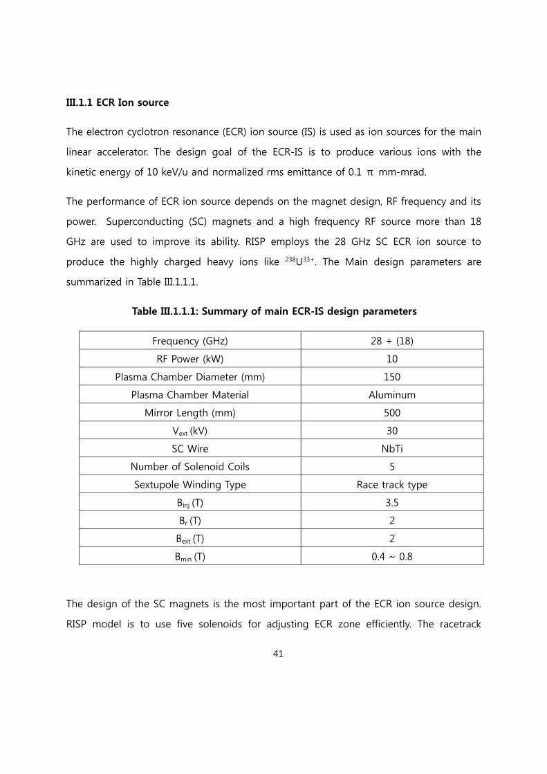
The performance of ECR ion source depends on the magnet design, RF frequency and its
power. Superconducting (SC) magnets and a high frequency RF source more than 18
GHz are used to improve its ability. RISP employs the 28 GHz SC ECR ion source to
produce the highly charged heavy ions like 238U33+. The Main design parameters are
summarized in Table III.1.1.1.
Table III.1.1.1: Summary of main ECR-IS design parameters
Frequency (GHz) 28 + (18)
RF Power (kW) 10
Plasma Chamber Diameter (mm) 150
Plasma Chamber Material Aluminum
Mirror Length (mm) 500
Vext (kV) 30
SC Wire NbTi
Number of Solenoid Coils 5
Sextupole Winding Type Race track type
Binj (T) 3.5
Br (T) 2
Bext (T) 2
Bmin (T) 0.4 ~ 0.8
The design of the SC magnets is the most important part of the ECR ion source design.
RISP model is to use five solenoids for adjusting ECR zone efficiently. The racetrack
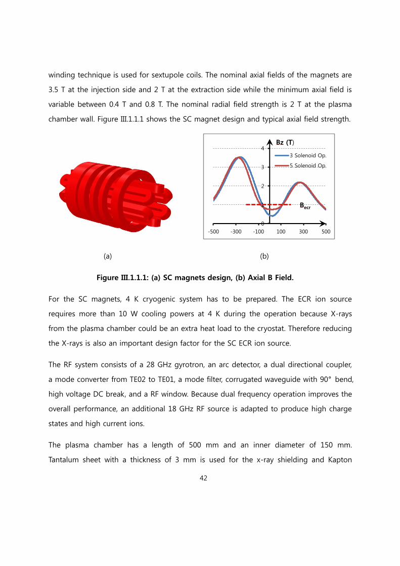
42
winding technique is used for sextupole coils. The nominal axial fields of the magnets are
3.5 T at the injection side and 2 T at the extraction side while the minimum axial field is
variable between 0.4 T and 0.8 T. The nominal radial field strength is 2 T at the plasma
chamber wall. Figure III.1.1.1 shows the SC magnet design and typical axial field strength.
(a) (b)
Figure III.1.1.1: (a) SC magnets design, (b) Axial B Field.
For the SC magnets, 4 K cryogenic system has to be prepared. The ECR ion source
requires more than 10 W cooling powers at 4 K during the operation because X-rays
from the plasma chamber could be an extra heat load to the cryostat. Therefore reducing
the X-rays is also an important design factor for the SC ECR ion source.
The RF system consists of a 28 GHz gyrotron, an arc detector, a dual directional coupler,
a mode converter from TE02 to TE01, a mode filter, corrugated waveguide with 90° bend,
high voltage DC break, and a RF window. Because dual frequency operation improves the
overall performance, an additional 18 GHz RF source is adapted to produce high charge
states and high current ions.
The plasma chamber has a length of 500 mm and an inner diameter of 150 mm.
Tantalum sheet with a thickness of 3 mm is used for the x-ray shielding and Kapton
0
1
2
3
4
-500 -300 -100 100 300 500
3 Solenoid Op.
5 Solenoid Op.
Bz (T)
z (mm)
Becr

43
sheet is used for electrical insulation of the plasma chamber wall. The isolated water
cooling system is connected to a pipe surrounding the plasma chamber wall. Two turbo
molecular pumps are installed below the injection and extraction boxes in order to make
UHV environment. The extraction electrode can be movable to maximize the beam
current and both sides of the plasma chamber are designed to move for the cryostat
installation and the maintenance. Additionally, a high temperature (2000 ℃) oven for
solid isotopes and a high voltage platform for heavy ions will be necessary.
III.1.2 Low Energy Beam Transport (LEBT)
The LEBT consists of two bends and quadrupoles for achromatic optics, solenoids for
beam matching between ECR-IS and RFQ, two bunchers, steering magnets, collimation
systems, and diagnostics. Figure III.1.2.1 shows the layout of the LEBT in the Front-End.
Figure III.1.2.2 shows designed optics and envelopes for the LEBT beam line. The optics
design is optimized by TRANSPORT code.
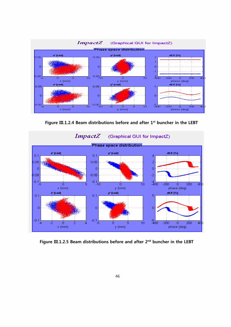
The dc beam from the ECR-IS is bunched before injection into the RFQ. For a short
bunch length with high bunching efficiency, two bunchers are applied. Beam simulation
code of IMPACT-Z is utilized for 6-dimension tracking that includes space charge force.
A normalized rms emittance of 0.1 pi mm-mrad and intrinsic energy spread of 0.05% are
considered. 20,000 macro-particles initially generated in 4-dimensional water-bag
transverse distributions with a uniform longitudinal distribution in phase space are
tracked in the beam simulation.

44
.
Figure III.1.2.1: Layout of the LEBT in the Front-End
Figure III.1.2.2: Designed optics and envelopes of the LEBT
Figure III.1.2.3 shows the initial beam distributions of two-charge state beam of 238U33+
and 238U34+ in the LEBT. Figure III.1.2.4 shows the beam distributions before and after the
2
2
4
4
6
6Vert
Horiz
RF
1
B V

45
first buncher. Figure III.1.2.5 shows the beam distributions before and after the second
buncher. Figure III.1.2.6 shows longitudinal beam distributions at the entrance of the RFQ.
It clearly shows that two-charge state beam can be accelerated at the same time in the
RFQ by matching phase space. The second buncher of 40.625 MHz is also used to match
the energy of two-charge state beams at the RFQ entrance. A distance between the
first buncher and the second buncher is 1.18 m for the two-charge state beam of 238U33+
and 238U34+
The beam simulation shows that the designed LEBT provides a good beam matching and
bunching for the two-charge state beam. Expected transverse and longitudinal
emittances are also obtained at the entrance of RFQ and the space-charge effects with
the U beam current of 400 euA in the LEBT is small.
Figure III.1.2.3 Initial beam distributions in the LEBT
46
Figure III.1.2.4 Beam distributions before and after 1st buncher in the LEBT
Figure III.1.2.5 Beam distributions before and after 2nd buncher in the LEBT

47
Figure III.1.2.6 Longitudinal beam distribution at the entrance of RFQ
III.1.3 RFQ
Radio Frequency Quadrupole (RFQ) is to bunch and accelerate beams transported from
the LEBT. It consists of a radial matching section, shaper, gentle buncher, and accelerating
section. The RFQ is designed to accelerate two-charge state (238U33+ and 238U34+ of 12pμA)
beams from 10 keV/u to 300 keV/u. The PARMTEQ is used to obtain the RFQ design
parameters. Table III.1.3.1 shows the main input parameters of RFQ. A charge state of
33.5 for the U beam simulation is used to mimic a multi-charge state beam.
Table III.1.3.1: Main parameters for RFQ
Reference Particles 238U33+ and 238U34+
RF Frequency 81.25 MHz
Input charge state 33.5
Input Energy 10 keV/u
Output Energy 300 keV/u
48
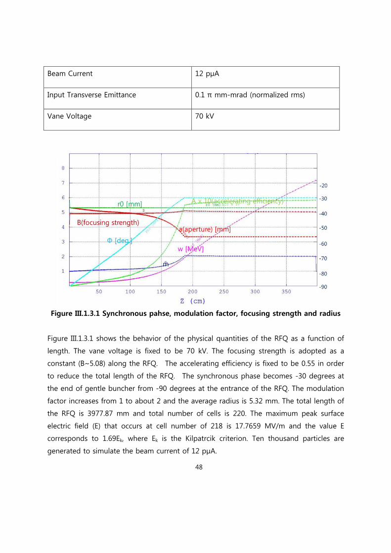
Beam Current 12 pμA
Input Transverse Emittance 0.1 π mm-mrad (normalized rms)
Vane Voltage 70 kV
Figure III.1.3.1 Synchronous pahse, modulation factor, focusing strength and radius
Figure III.1.3.1 shows the behavior of the physical quantities of the RFQ as a function of
length. The vane voltage is fixed to be 70 kV. The focusing strength is adopted as a
constant (B~5.08) along the RFQ. The accelerating efficiency is fixed to be 0.55 in order
to reduce the total length of the RFQ. The synchronous phase becomes -30 degrees at
the end of gentle buncher from -90 degrees at the entrance of the RFQ. The modulation
factor increases from 1 to about 2 and the average radius is 5.32 mm. The total length of
the RFQ is 3977.87 mm and total number of cells is 220. The maximum peak surface
electric field (E) that occurs at cell number of 218 is 17.7659 MV/m and the value E
corresponds to 1.69Ek, where Ek is the Kilpatrcik criterion. Ten thousand particles are
generated to simulate the beam current of 12 pμA.
49
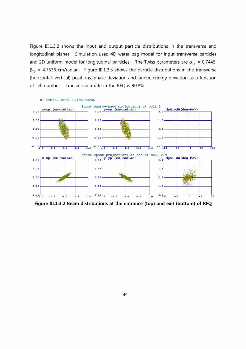
Figure III.1.3.2 shows the input and output particle distributions in the transverse and
longitudinal planes. Simulation used 4D water bag model for input transverse particles
and 2D uniform model for longitudinal particles. The Twiss parameters are αx,y = 0.7445,
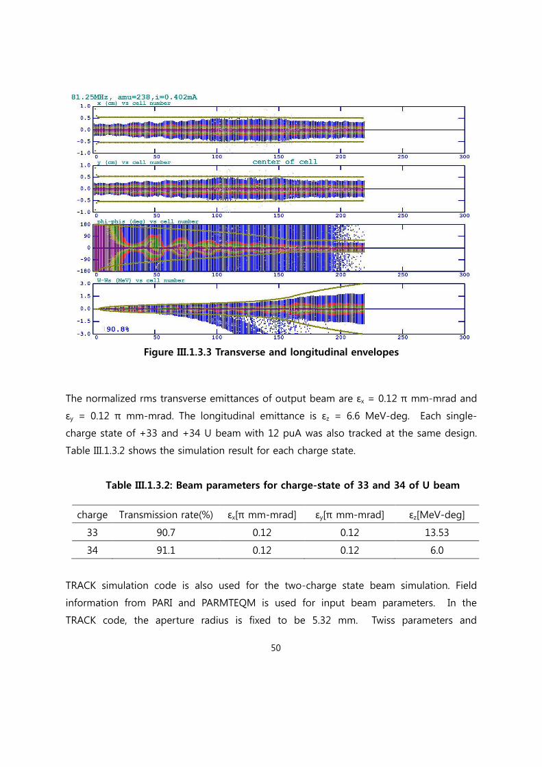
βx,y = 4.7536 cm/radian. Figure III.1.3.3 shows the particle distributions in the transverse
(horizontal, vertical) positions, phase deviation and kinetic energy deviation as a function
of cell number. Transmission rate in the RFQ is 90.8%.
Figure III.1.3.2 Beam distributions at the entrance (top) and exit (bottom) of RFQ
50
Figure III.1.3.3 Transverse and longitudinal envelopes
The normalized rms transverse emittances of output beam are εx = 0.12 π mm-mrad and
εy = 0.12 π mm-mrad. The longitudinal emittance is εz = 6.6 MeV-deg. Each single-
charge state of +33 and +34 U beam with 12 puA was also tracked at the same design.
Table III.1.3.2 shows the simulation result for each charge state.
Table III.1.3.2: Beam parameters for charge-state of 33 and 34 of U beam
charge Transmission rate(%) εx[π mm-mrad] εy[π mm-mrad] εz[MeV-deg]
33 90.7 0.12 0.12 13.53
34 91.1 0.12 0.12 6.0
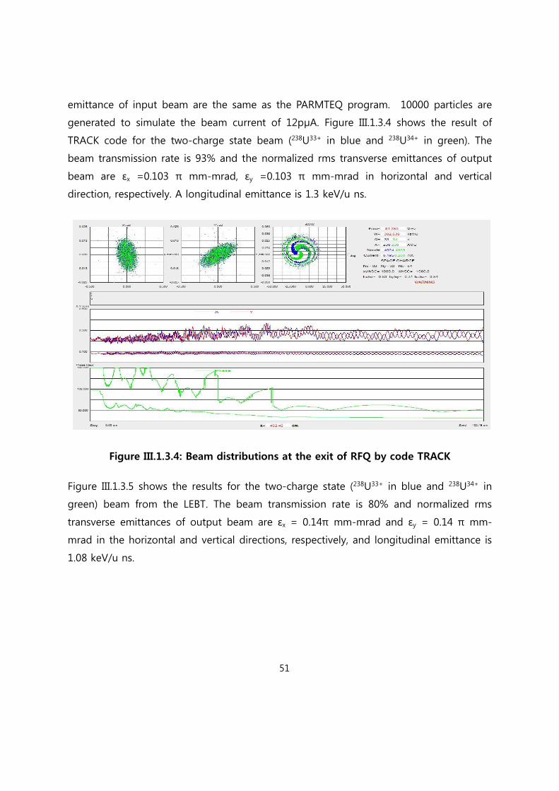
TRACK simulation code is also used for the two-charge state beam simulation. Field
information from PARI and PARMTEQM is used for input beam parameters. In the
TRACK code, the aperture radius is fixed to be 5.32 mm. Twiss parameters and
51
emittance of input beam are the same as the PARMTEQ program. 10000 particles are
generated to simulate the beam current of 12pμA. Figure III.1.3.4 shows the result of
TRACK code for the two-charge state beam (238U33+ in blue and 238U34+ in green). The
beam transmission rate is 93% and the normalized rms transverse emittances of output
beam are εx =0.103 π mm-mrad, εy =0.103 π mm-mrad in horizontal and vertical
direction, respectively. A longitudinal emittance is 1.3 keV/u ns.
Figure III.1.3.4: Beam distributions at the exit of RFQ by code TRACK
Figure III.1.3.5 shows the results for the two-charge state (238U33+ in blue and 238U34+ in
green) beam from the LEBT. The beam transmission rate is 80% and normalized rms
transverse emittances of output beam are εx = 0.14π mm-mrad and εy = 0.14 π mm-
mrad in the horizontal and vertical directions, respectively, and longitudinal emittance is
1.08 keV/u ns.

52
Figure III.1.3.5 Beam distributions at the exit of RFQ by code TRACK when the beam
from the LEBT is used
II.1.4 Medium Energy Beam Transport (MEBT)
The Medium Energy Beam Transport (MEBT) system located between the RFQ and
superconducting linac (SCL), requires to match the optical parameters in transverse plane
and to remove the unaccelerated ion beams from the RFQ. It also includes beam
diagnostic devices to measure the beam quality.
III.1.4.1 MEBT Beam Optics Design
The optics design of the MEBT system was performed by using TRACE3D code and
particle tracking was performed using IMPACT-Z code. Basically the optics function was
matched to the betatron function at the entrance of the SCL. The MEBT design is to
transfer the two-charge state beams of the U33+ and U34+. The schematic layout of the
MEBT is shown in Figure III.1.4.1.1. The MEBT system is designed to have enough spaces
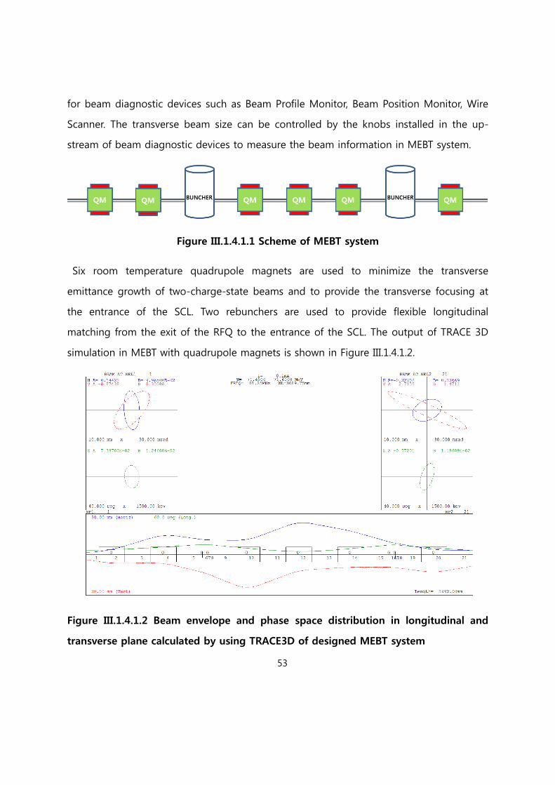
53
for beam diagnostic devices such as Beam Profile Monitor, Beam Position Monitor, Wire
Scanner. The transverse beam size can be controlled by the knobs installed in the up-
stream of beam diagnostic devices to measure the beam information in MEBT system.
Figure III.1.4.1.1 Scheme of MEBT system
Six room temperature quadrupole magnets are used to minimize the transverse
emittance growth of two-charge-state beams and to provide the transverse focusing at
the entrance of the SCL. Two rebunchers are used to provide flexible longitudinal
matching from the exit of the RFQ to the entrance of the SCL. The output of TRACE 3D
simulation in MEBT with quadrupole magnets is shown in Figure III.1.4.1.2.
Figure III.1.4.1.2 Beam envelope and phase space distribution in longitudinal and
transverse plane calculated by using TRACE3D of designed MEBT system

54
IMPACT-Z code is used to estimate the space charge effects in the MEBT system and its
simulation results are shown in Figure III.1.4.1.3. The quadrupole magnets have a field of
less than 0.5 T at the pole-tip. The rebuncher will be an 81.25 MHz βopt = 0.025 λ/4
room temperature resonator. The total length of the MEBT is about 3 meters.
Figure III.1.4.1.3 Beam envelope and phase space distribution in longitudinal and
transverse plane calculated by using IMPACT-Z of designed MEBT system
III.1.4.2 Front-end beam simulation
Figure III.1.4.2.1 shows beam envelope and phase space distribution in longitudinal
and transverse planes at the MEBT when the front-end beam simulations including the
LEBT and RFQ are performed. Table III.1.4.2.3 shows the summary of the beam
parameters and particle transmission that are obtained by front-end beam simulations.

55
Figure III.1.4.2.1 Beam envelope and phase space distribution in longitudinal and
transverse planes in the MEBT by the front-end beam simulations
Table 1.4.2.3 Summary of the beam parameters from Front-End simulations
With
Bunchers
Number of
Particle
Transm.
Efficiency(%)
Current[mA]
33+, 34+
Nor.rms_x
[mmmrad]
Nor. rms _y
[mmmrad]
Nor. rms _z
[deg-MeV]
Initial 20000 100 0.22, 0.17 0.100 0.100 3.66
LEBT 19253 96.27 0.22, 0.16 0.109 0.174 3.15
RFQ 16093 80.47 0.19, 0.13 0.122 0.183 8.27
MEBT 15790 78.95 0.19, 0.12 0.123 0.181 8.22

56
III.1.5 Super Conducting Linac (SCL)
III.1.5.1 Frequency Choice
Study has been conducted for the choice of the base frequency of the Superconducting
Linac (SCL). A case is studied with the base frequency higher than 70 MHz, because
higher frequency means higher efficiency in general. The following factors are considered:
Do broad base of world class labs exist that use the frequency, which means that
there are subsystems available and that the project can save R&D cost?
Mechanical rigidity of a cavity increases for higher frequency.
Many labs have chosen their frequency based on their history and boundary
conditions.
Choice of frequency needs to be backed by beam dynamics.
An investigation shows that there are two major camps of frequency choice. One camp
prefers 81.25 MHz (and multiples of this frequency) including ANL, FNAL, TRIUMF, IMP
etc, and the other prefers 88 MHz (and multiples of this frequency) including SPIRAL2,
CERN, ESS, SARAF etc. Feasibility studies based on beam physics of the SCL are
conducted with 81.25 MHz as the base frequency and no show-stopper has been found.
A choice between 81.25 MHz and 88 MHz is recommended considering collaboration
aspects and the availability of subsystem components. And a decision is made to choose
81.25 MHz as the base frequency of the facility.
III.1.5.2 Driver Superconducting Linac (SCL) Lattice
It is known that the position of each component in a cryomodule changes by no less
than a millimeter in a random fashion during the cool-down of a cryomodule and it is
extremely difficult to predict accurately enough alignment of superconducting solenoids

57
in a cryomodule after the cool-down. Accurate alignment of focusing elements such as
superconducting (SC) solenoids is very crucial for maintaining the beam quality of high
intensity beams which is envisioned for the heavy ion accelerator. For high intensity
operations, the foreseen uncertainty of no less than a millimeter displacement can induce
intolerable level of beam loss, leading to activation of accelerator components and
potential quench of superconductors inside cryomodules.
The previous SCL design with SC solenoids presents the following challenges and issues:
Alignment of SC solenoids is not trivial to control. It is known that components in a
cryomodule can move no less than a millimeter during cool-down.
Small misalignment of SC solenoids by ±0.5 mm generates significant emittance
growth (simulations indicate factor 2.5 emittance growth by the end of the short
beta=0.047 SCL11).
Heat deposit by beam loss in the SC solenoids can be an issue such as quench.
Operation of the SCL is not trivial for example due to the magnetization of
surrounding elements in the cryomodule.
It is found that the matching between different segments of the SCL is challenging.
And the design is not optimized.
The solenoids in the beta=0.041 segment are very short (12 cm long) and the
required field can go as high as 11 Tesla.
The SCL1 employs long cryomodules that contain 8 cavities and 3 or 8 solenoids.
This design imposes significant restriction on the beam diagnostics access and this
leads to difficulties in the accelerator tuning for a high intensity operation.

58
These points raised concerns and studies have been initiated to come up with a better
SCL lattice design that can enable high intensity beam operations by improving the
beam quality and straightening complexities. These are crucial design considerations in
designing the SCL, for the intensity heavy ion beams has increased steadily. The SPIRAL2
project also adopted quadrupole doublet focusing lattice for the high intensity ion beam
acceleration (for instance 1 mA of heavy ion beams and 5 mA deuteron beam) [III.1.5.2.1].
Studies have identified that the SCL lattice with normal conducting (NC) quadrupole
doublets has the following advantages:
High intensity beam acceleration and operation are easy – by adopting quadrupole
magnets outside the cryomodule. Quadrupole doublets can be aligned better than
±150 m.
Through beam dynamics simulations with machine imperfections, we get a very small
beam emittance growth in transverse planes, demonstrating that the proposed
design is more suitable for high intensity ion beam acceleration.
Beam boxes between the doublets are regularly placed along the SCL and are
reserved for beam diagnostics and collimators. This configuration provides complete
beam diagnostics coverage. This is very crucial for tuning for high intensity operation.
Quadrupoles are integrated with a dipole steering element due to their compact
design. Orbit corrections are done using the dipole correctors coupled with BPMs
(Beam position Monitors).
The linac has the same quadrupole lattice with the charge stripping section and the
following beam lines.
Cost estimation shows little difference from the cost of the previous design.
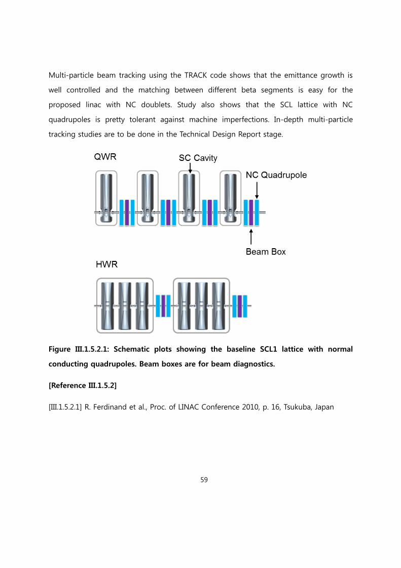
59
Multi-particle beam tracking using the TRACK code shows that the emittance growth is
well controlled and the matching between different beta segments is easy for the
proposed linac with NC doublets. Study also shows that the SCL lattice with NC
quadrupoles is pretty tolerant against machine imperfections. In-depth multi-particle
tracking studies are to be done in the Technical Design Report stage.
Figure III.1.5.2.1: Schematic plots showing the baseline SCL1 lattice with normal
conducting quadrupoles. Beam boxes are for beam diagnostics.
[Reference III.1.5.2]
[III.1.5.2.1] R. Ferdinand et al., Proc. of LINAC Conference 2010, p. 16, Tsukuba, Japan

60
III.1.5.3 Geometric Betas, Types and Parameters of Superconducting Cavities
Over all the design choice of cavities is optimized for high intensity operations
anticipating that the performance ion sources will improve ever in the future. Compared
with the previous design, the Quarter Wave Resonator (QWR) segment is minimized by
eliminating the second family of the g = 0.085 QWR because of the dipole kick and the
asymmetric field of QWR. The second QWR segment is replaced with g = 0.12 Half
Wave Resonator (HWR) segment. Unlike QWR, HWR does not have the -dependent
dipole kick due to their symmetric nature of electro-magnetic fields of the cavity. By
adopting HWR, beam quality control becomes easier especially for high intensity beam
operation.
Figure III.1.5.3.1: Plots of energy gain for the Uranium beam with the optimized set
of g=[0.047, 0.12, 0.30, 0.53]. For QWR and HWR, U+33 beam is used and for SSR1
and SSR2, U+79 beam is used.
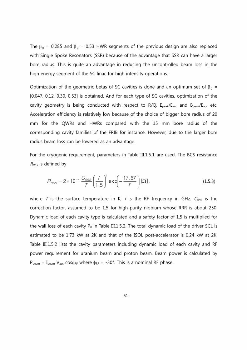
61
The g = 0.285 and g = 0.53 HWR segments of the previous design are also replaced
with Single Spoke Resonators (SSR) because of the advantage that SSR can have a larger
bore radius. This is quite an advantage in reducing the uncontrolled beam loss in the
high energy segment of the SC linac for high intensity operations.
Optimization of the geometric betas of SC cavities is done and an optimum set of g =
[0.047, 0.12, 0.30, 0.53] is obtained. And for each type of SC cavities, optimization of the
cavity geometry is being conducted with respect to R/Q, Epeak/Eacc and Bpeak/Eacc etc.
Acceleration efficiency is relatively low because of the choice of bigger bore radius of 20
mm for the QWRs and HWRs compared with the 15 mm bore radius of the
corresponding cavity families of the FRIB for instance. However, due to the larger bore
radius beam loss can be lowered as an advantage.
For the cryogenic requirement, parameters in Table III.1.5.1 are used. The BCS resistance
RBCS is defined by
][67.17
exp5.1
102
2
4
T
f
T
CR RRR
BCS , (1.5.3)
where T is the surface temperature in K, f is the RF frequency in GHz. CRRR is the
correction factor, assumed to be 1.5 for high-purity niobium whose RRR is about 250.
Dynamic load of each cavity type is calculated and a safety factor of 1.5 is multiplied for
the wall loss of each cavity P0 in Table III.1.5.2. The total dynamic load of the driver SCL is
estimated to be 1.73 kW at 2K and that of the ISOL post-accelerator is 0.24 kW at 2K.
Table III.1.5.2 lists the cavity parameters including dynamic load of each cavity and RF
power requirement for uranium beam and proton beam. Beam power is calculated by
Pbeam = Ibeam Vacc cosRF where RF = -30°. This is a nominal RF phase.

62
Table III.1.5.1 Surface Resistance for the SC Cavities.
Parameters Unit QWR HWR SSR
Resonant frequency MHz 81.25 162.5 325
Operating temperature K 2 2 2
CRRR - 1.5 1.5 1.5
RBCS n 0.06 0.26 1.02
Rres n 10 10 10
Rs n 10.06 10.26 11.02
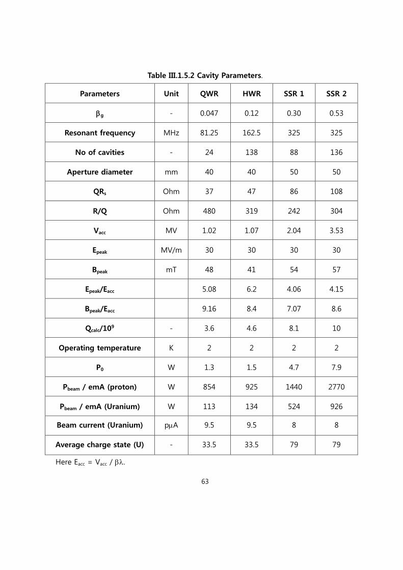
63
Table III.1.5.2 Cavity Parameters.
Parameters Unit QWR HWR SSR 1 SSR 2
g - 0.047 0.12 0.30 0.53
Resonant frequency MHz 81.25 162.5 325 325
No of cavities - 24 138 88 136
Aperture diameter mm 40 40 50 50
QRs Ohm 37 47 86 108
R/Q Ohm 480 319 242 304
Vacc MV 1.02 1.07 2.04 3.53
Epeak MV/m 30 30 30 30
Bpeak mT 48 41 54 57
Epeak/Eacc 5.08 6.2 4.06 4.15
Bpeak/Eacc 9.16 8.4 7.07 8.6
Qcalc/109 - 3.6 4.6 8.1 10
Operating temperature K 2 2 2 2
P0 W 1.3 1.5 4.7 7.9
Pbeam / emA (proton) W 854 925 1440 2770
Pbeam / emA (Uranium) W 113 134 524 926
Beam current (Uranium) pA 9.5 9.5 8 8
Average charge state (U) - 33.5 33.5 79 79
Here Eacc = Vacc / .
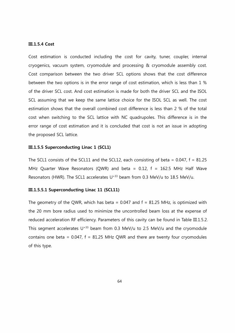
64
III.1.5.4 Cost
Cost estimation is conducted including the cost for cavity, tuner, coupler, internal
cryogenics, vacuum system, cryomodule and processing & cryomodule assembly cost.
Cost comparison between the two driver SCL options shows that the cost difference
between the two options is in the error range of cost estimation, which is less than 1 %
of the driver SCL cost. And cost estimation is made for both the driver SCL and the ISOL
SCL assuming that we keep the same lattice choice for the ISOL SCL as well. The cost
estimation shows that the overall combined cost difference is less than 2 % of the total
cost when switching to the SCL lattice with NC quadrupoles. This difference is in the
error range of cost estimation and it is concluded that cost is not an issue in adopting
the proposed SCL lattice.
III.1.5.5 Superconducting Linac 1 (SCL1)
The SCL1 consists of the SCL11 and the SCL12, each consisting of beta = 0.047, f = 81.25
MHz Quarter Wave Resonators (QWR) and beta = 0.12, f = 162.5 MHz Half Wave
Resonators (HWR). The SCL1 accelerates U+33 beam from 0.3 MeV/u to 18.5 MeV/u.
III.1.5.5.1 Superconducting Linac 11 (SCL11)
The geometry of the QWR, which has beta = 0.047 and f = 81.25 MHz, is optimized with
the 20 mm bore radius used to minimize the uncontrolled beam loss at the expense of
reduced acceleration RF efficiency. Parameters of this cavity can be found in Table III.1.5.2.
This segment accelerates U+33 beam from 0.3 MeV/u to 2.5 MeV/u and the cryomodule
contains one beta = 0.047, f = 81.25 MHz QWR and there are twenty four cryomodules
of this type.

65
Figure III.1.5.5.1 Plot showing the geometry of beta=0.047, f=81.25 MHz Quarter
Wave Resonator.
Figure III.1.5.5.2 Schematic plot of the beta=0.047, f=81.25 MHz segment with
normal conducting quadrupoles in blue and diagnostics beam boxes in purple.
III.1.5.5.2 Superconducting Linac 12 (SCL12)
The geometry of the f=162.5 MHz beta=0.12 Half Wave Resonator is optimized with the
bore radius 20 mm. Parameters of this cavity can be found in Table III.1.5.2. This segment
accelerates U+33 beam from 2.5 MeV/u to 18.5 MeV/u and there are two types of
cryomodules, one type containing 3 beta=0.12, f=162.5 MHz Half Wave Resonators and
the other containing 6 beta=0.12, f=162.5 MHz Half Wave Resonators.

66
Figure III.1.5.5.3 Plot showing the geometry of beta=0.12, f=162.5 MHz Half Wave
Resonator.
Figure III.1.5.5.4 Schematic plot of the beta=0.12, f=162.5 MHz segment with normal
conducting quadrupoles in blue and diagnostics beam boxes in purple.
III.1.5.6 Charge Stripper Section
One of the critical components of the superconducting Linac (SCL) is the charge stripper
because of high power deposited in the stripping material in a small area. Charge
stripper strips electrons from heavy ion beams to enhance the acceleration efficiency in
the following SCL2.

67
Figure III.1.5.6.1 Layout of the Charge stripper section
Figure III.1.5.6.1 shows the layout of charge stripper section. This section consists of the
rooms for installation of solid, liquid and gas type charge stripper. It also consists of
matching section to prevent the beam divergence due to the large angle and charge
selection section. The charge stripper is reserved to accommodate the liquid Li and
thin carbon foil at the down-stream of the SCL1. Five charge state ion beams, which
are selected in charge selection section, are matched to transfer to SCL2 by using
matching section.
Recent studies done by FRIB indicate that carbon foils show fast decay of performance,
which makes this type of stripper is very unlikely to satisfy the FRIB requirements
[III.1.5.6.1]. The FRIB looks at other options of the charge stripper which include liquid
lithium stripper developed at the ANL, gas stripper, gas stripper with plasma windows,
and plasma stripper [III.1.5.6.2]. The charge stripper section is designed to include
enough space for the options being considered. Collaboration and intense R&D efforts
are in need. Even though carbon foils may have defects in full beam power, it is still

68
useful for low beam power operation. It is also planned to use the carbon foil during the
testing, commissioning, and possibly early low power operation stages. Preliminary
study is conducted about the carbon foils using the LISE++ code.
III.1.5.6.1 Charge Stripping Foil
To optimize the energy at the exit of the SCL1, the dependency of the efficiency of the
charge stripping as a function of the incident energy is investigated. It is performed by
using LISE++ code which can calculate the charge stripping of Uranium ions in carbon
foil and liquid Li. First, the efficiency of the charge stripping of Uranium 33+ ions with
300 μg/cm2 carbon foils is calculated as a function of the energy of incident beam. It is
shown in Figure III.1.5.6.1.1
Figure III.1.5.6.1.1 Charge distribution as a function of the incident ion beam energy
with 300 μg/cm2 carbon foil

69
Table III.1.5.6.1 Charge state and population
Based on this calculation, the ion beam energy at the exit of the SCL1 is optimized
around 18.5 MeV/u to get the more efficient acceleration in the SCL2.
III.1.5.6.2 Optics design for installation of charge stripper
Enough straight section is reserved to accommodate the liquid Li and carbon foil
charge strippers at the down-stream of the SCL1 illustrated in Figure III.1.5.6.2.1. A
small beam size and a short bunch length are also necessary. A small transverse
beam size, however, leads to high beam power density on the stripper. Therefore, the
optics design is performed to get the acceptable beam size and bunch length on the
stripper. To control the beam size of beam on the stripper, two room-temperature
quadrupole magnets are installed at the up-stream of each stripper. The total length
of this beam line is 17.4 meters.
Figure III.1.5.6.2.1 Layout of the stripper installation section
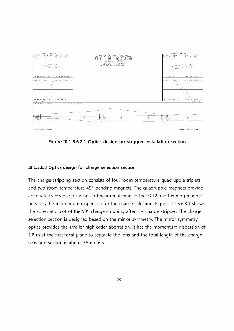
70
Figure III.1.5.6.2.1 Optics design for stripper installation section
III.1.5.6.3 Optics design for charge selection section
The charge stripping section consists of four room-temperature quadrupole triplets
and two room-temperature 45° bending magnets. The quadrupole magnets provide
adequate transverse focusing and beam matching to the SCL2 and bending magnet
provides the momentum dispersion for the charge selection. Figure III.1.5.6.3.1 shows
the schematic plot of the 90° charge stripping after the charge stripper. The charge
selection section is designed based on the mirror symmetry. The mirror symmetry
optics provides the smaller high order aberration. It has the momentum dispersion of
1.8 m at the first focal plane to separate the ions and the total length of the charge
selection section is about 9.8 meters.

71
Figure III.1.5.6.3.1 Scheme of charge stripping section
Figure III.1.5.6.3.2 Result of the tracking simulation using TRACK code

72
The multi-particle tracking simulation is performed using TRACK code. As shown by
Figure III.1.5.6.3.2, the multi-charge-state ion beam is well separated in horizontal plane
at the dispersive section. Hence, we can select the charge state of the ion using the slit
which is installed in the dispersive section.
III.1.5.6.4 Optics design for matching section
Since the effect of the scattering inside of charge stripper, the angle of the ion beam
is increased. Hence the matching section at the down-stream of the charge stripper
is required to compensate the effect of the large angle in charge selection section.
After passing the charge selection section, the matching for SCL2 is required in
transverse and longitudinal direction. Hence the matching section, which consists of the
four room-temperature quadrupole magnets, is installed in a down-stream of the
charge selection section. And the buncher will also be installed between the charge
selection section and matching section to protect the divergence in longitudinal
direction. The whole layout with the sections for charge stripper, charge selection and
matching section is shown in Figure III.1.5.6.1. The multi-particle tracking simulation
was performed by using TRACK code with the solid carbon foil charge stripper.

73
Figure III.1.5.6.4.1 Result of the tracking simulation using TRACK code
[Reference III.1.5.6]
[III.1.5.6.1] F. Marti et al., Proc. of LINAC Conference 2010, p. 659, Tsukuba, Japan
[III1.5.6.2] F. Marti et al., Proc. of LINAC Conference 2010, p. 662, Tsukuba, Japan
III.1.5.7 Superconducting Linac 2 (SCL2)
The SCL2 consists of the SCL21 and the SCL22, each consisting of beta = 0.30, f = 325
MHz Single Spoke Resonators (SSR) and beta = 0.53, f = 325 MHz SSR. The SCL2
accelerates U+79 beam from 18.5 MeV/u to 200 MeV/u. Single Spoke Resonator type is
chosen mainly because it can have a larger bore radius compared with the Half Wave
Resonator type, which is very essential to reduce the uncontrolled beam loss in the high
energy segments of the SCL.

74
III.1.5.7.1 Superconducting Linac 21 (SCL21)
This SCL21 accelerates for example U+79 beam from 18.5 MeV/u to 70.9 MeV/u and there
are 22 cryomodules each of which contains 4 beta=0.30, f=325 MHz Single Spoke
Resonators. Parameters of this cavity can be found in Table III.1.6.2.
Figure III.1.5.7.1 Schematic plot of the beta=0.30, f=325 MHz cavity with its EM
fields.
Figure III.1.5.7.2 Schematic plot of the beta=0.30, f=325 MHz segment cryomodule
with normal conducting quadrupoles in blue and diagnostics beam boxes in purple.
III.1.5.7.2 Superconducting Linac 22 (SCL22)
This SCL22 accelerates for example U+79 beam from 70.9 MeV/u to 200 MeV/u and there
are 17 cryomodules each of which contains 8 beta=0.53, f=325 MHz Single Spoke
Resonators. Parameters of this cavity can be found in Table III.1.5.2.
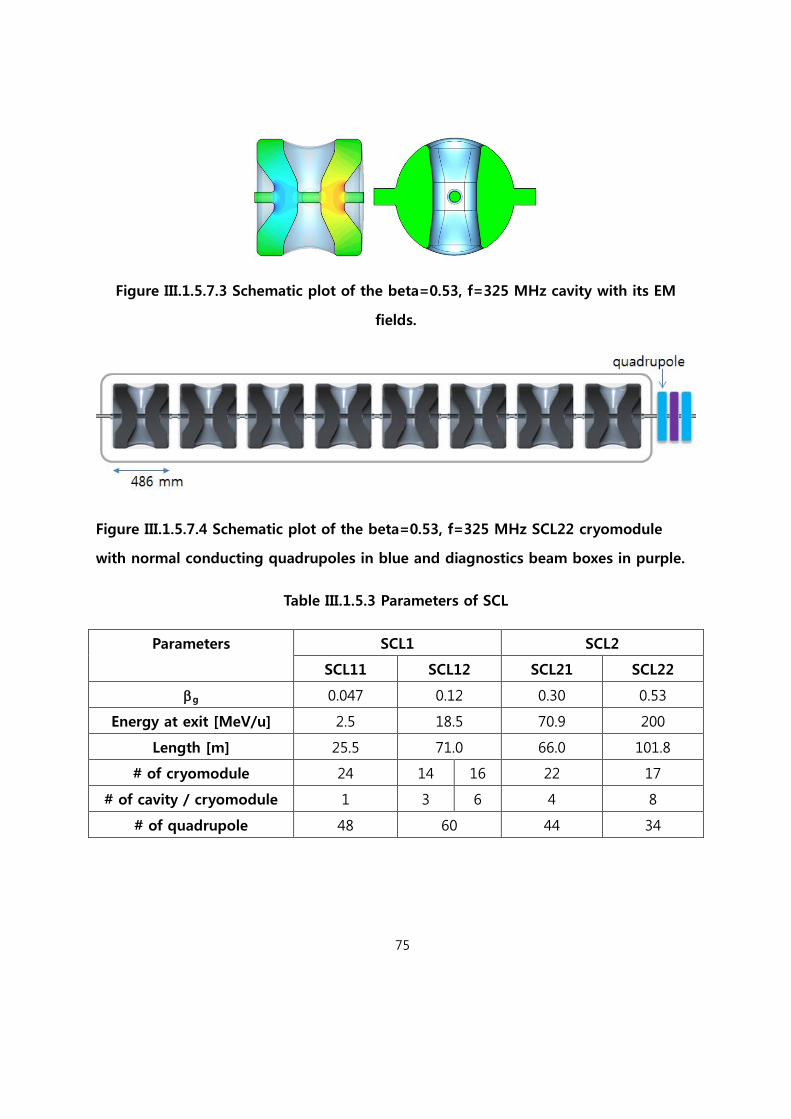
75
Figure III.1.5.7.3 Schematic plot of the beta=0.53, f=325 MHz cavity with its EM
fields.
Figure III.1.5.7.4 Schematic plot of the beta=0.53, f=325 MHz SCL22 cryomodule
with normal conducting quadrupoles in blue and diagnostics beam boxes in purple.
Table III.1.5.3 Parameters of SCL
Parameters SCL1 SCL2
SCL11 SCL12 SCL21 SCL22
g 0.047 0.12 0.30 0.53
Energy at exit [MeV/u] 2.5 18.5 70.9 200
Length [m] 25.5 71.0 66.0 101.8
# of cryomodule 24 14 16 22 17
# of cavity / cryomodule 1 3 6 4 8
# of quadrupole 48 60 44 34
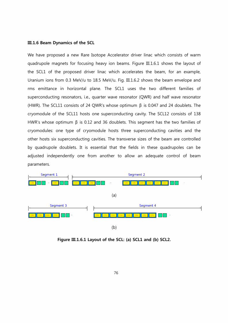
76
III.1.6 Beam Dynamics of the SCL
We have proposed a new Rare Isotope Accelerator driver linac which consists of warm
quadrupole magnets for focusing heavy ion beams. Figure III.1.6.1 shows the layout of
the SCL1 of the proposed driver linac which accelerates the beam, for an example,
Uranium ions from 0.3 MeV/u to 18.5 MeV/u. Fig. III.1.6.2 shows the beam envelope and
rms emittance in horizontal plane. The SCL1 uses the two different families of
superconducting resonators, i.e., quarter wave resonator (QWR) and half wave resonator
(HWR). The SCL11 consists of 24 QWR’s whose optimum β is 0.047 and 24 doublets. The
cryomodule of the SCL11 hosts one superconducting cavity. The SCL12 consists of 138
HWR’s whose optimum β is 0.12 and 36 doublets. This segment has the two families of
cryomodules: one type of cryomodule hosts three superconducting cavities and the
other hosts six superconducting cavities. The transverse sizes of the beam are controlled
by quadrupole doublets. It is essential that the fields in these quadrupoles can be
adjusted independently one from another to allow an adequate control of beam
parameters.
(a)
(b)
Figure III.1.6.1 Layout of the SCL: (a) SCL1 and (b) SCL2.

77
(a)
(b)
(c)
(d)
Figure III.1.6.2 Plot of (a) horizontal rms beam envelope and (b) horizontal rms
emittance for SCL1, and (c) horizontal rms beam envelope and (d) horizontal rms
emittance for SCL2 for doublet-based lattice. Misalignment and field error are not
included in the lattice.

78
Figure III.1.6.3 Plot of phase space for multi-charge-state Uranium beam: (top)
entrance of β1 section, (1st row) exit of β1 section, (2nd row) exit of β2 section, (3rd
row) exit of β3 section, and (bottom) exit of β4 section.
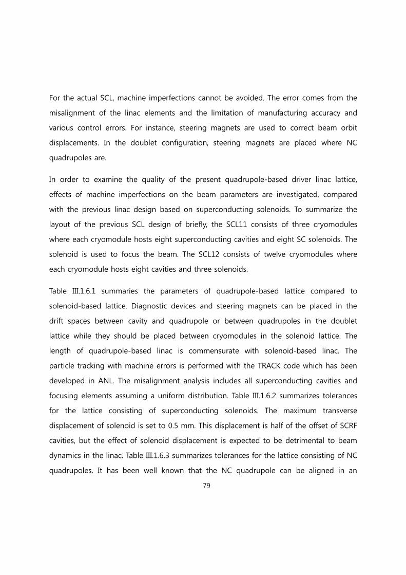
79
For the actual SCL, machine imperfections cannot be avoided. The error comes from the
misalignment of the linac elements and the limitation of manufacturing accuracy and
various control errors. For instance, steering magnets are used to correct beam orbit
displacements. In the doublet configuration, steering magnets are placed where NC
quadrupoles are.
In order to examine the quality of the present quadrupole-based driver linac lattice,
effects of machine imperfections on the beam parameters are investigated, compared
with the previous linac design based on superconducting solenoids. To summarize the
layout of the previous SCL design of briefly, the SCL11 consists of three cryomodules
where each cryomodule hosts eight superconducting cavities and eight SC solenoids. The
solenoid is used to focus the beam. The SCL12 consists of twelve cryomodules where
each cryomodule hosts eight cavities and three solenoids.
Table III.1.6.1 summaries the parameters of quadrupole-based lattice compared to
solenoid-based lattice. Diagnostic devices and steering magnets can be placed in the
drift spaces between cavity and quadrupole or between quadrupoles in the doublet
lattice while they should be placed between cryomodules in the solenoid lattice. The
length of quadrupole-based linac is commensurate with solenoid-based linac. The
particle tracking with machine errors is performed with the TRACK code which has been
developed in ANL. The misalignment analysis includes all superconducting cavities and
focusing elements assuming a uniform distribution. Table III.1.6.2 summarizes tolerances
for the lattice consisting of superconducting solenoids. The maximum transverse
displacement of solenoid is set to 0.5 mm. This displacement is half of the offset of SCRF
cavities, but the effect of solenoid displacement is expected to be detrimental to beam
dynamics in the linac. Table III.1.6.3 summarizes tolerances for the lattice consisting of NC
quadrupoles. It has been well known that the NC quadrupole can be aligned in an
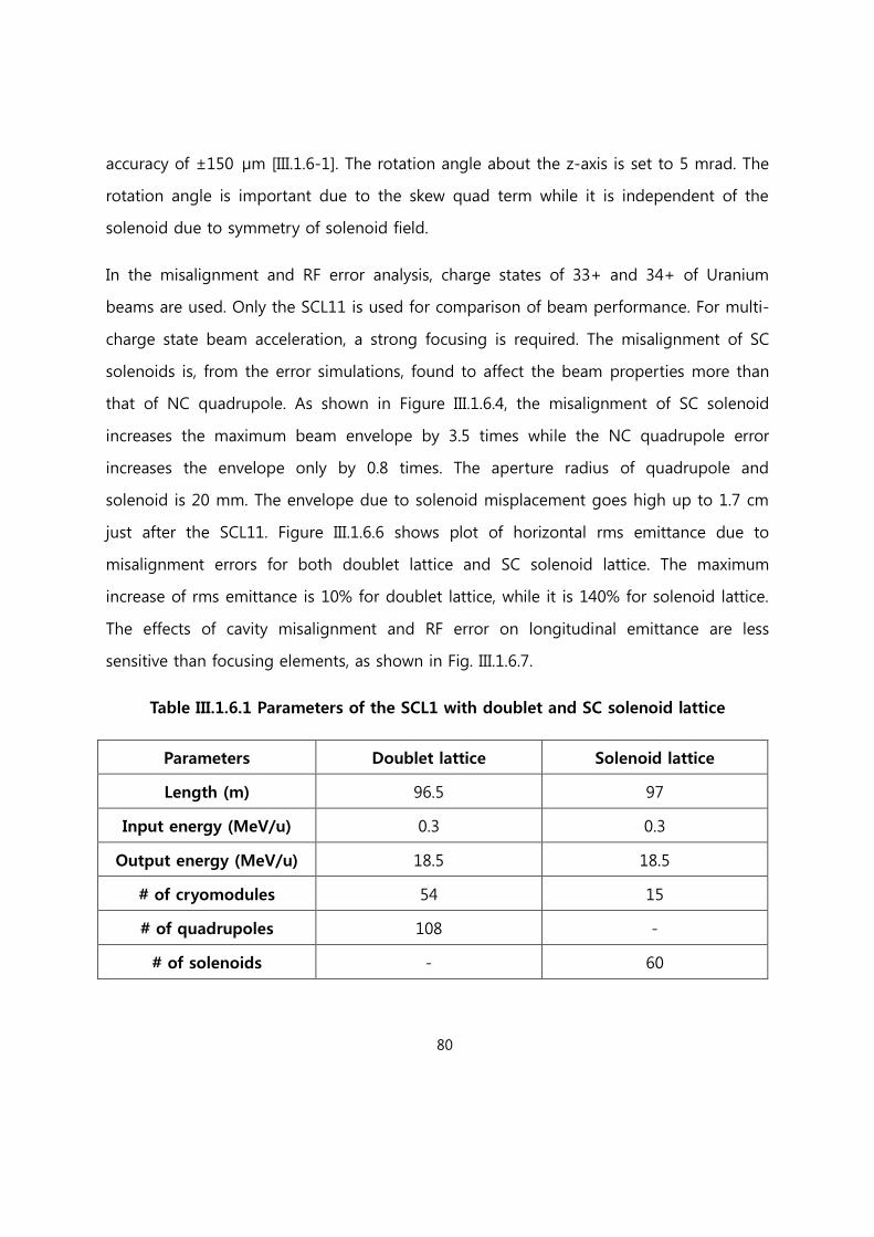
80
accuracy of ±150 μm [III.1.6-1]. The rotation angle about the z-axis is set to 5 mrad. The
rotation angle is important due to the skew quad term while it is independent of the
solenoid due to symmetry of solenoid field.
In the misalignment and RF error analysis, charge states of 33+ and 34+ of Uranium
beams are used. Only the SCL11 is used for comparison of beam performance. For multi-
charge state beam acceleration, a strong focusing is required. The misalignment of SC
solenoids is, from the error simulations, found to affect the beam properties more than
that of NC quadrupole. As shown in Figure III.1.6.4, the misalignment of SC solenoid
increases the maximum beam envelope by 3.5 times while the NC quadrupole error
increases the envelope only by 0.8 times. The aperture radius of quadrupole and
solenoid is 20 mm. The envelope due to solenoid misplacement goes high up to 1.7 cm
just after the SCL11. Figure III.1.6.6 shows plot of horizontal rms emittance due to
misalignment errors for both doublet lattice and SC solenoid lattice. The maximum
increase of rms emittance is 10% for doublet lattice, while it is 140% for solenoid lattice.
The effects of cavity misalignment and RF error on longitudinal emittance are less
sensitive than focusing elements, as shown in Fig. III.1.6.7.
Table III.1.6.1 Parameters of the SCL1 with doublet and SC solenoid lattice
Parameters Doublet lattice Solenoid lattice
Length (m) 96.5 97
Input energy (MeV/u) 0.3 0.3
Output energy (MeV/u) 18.5 18.5
# of cryomodules 54 15
# of quadrupoles 108 -
# of solenoids - 60

81
Table III.1.6.2 Machine imperfection for the SC solenoid lattice
Parameters SC Cavities SC Solenoids Comment
Displacement (mm) ±1.0 ±0.5 Uniform
Phase (deg) ±1 - 3σ Gaussian
Amplitude (%) ±1 - 3σ Gaussian
Rotation (mrad) - ±5.0 Uniform
Table III.1.6.3 Machine imperfection for the NC quadrupole lattice
Parameters SC Cavities Warm Quadrupoles Comment
Displacement (mm) ±1.0 ±0.15 Uniform
Phase (deg) ±1 - 3σ Gaussian
Amplitude (%) ±1 - 3σ Gaussian
Rotation (mrad) - ±5.0 Uniform
Table III.1.6.4 Variation of beam parameters due to machine imperfections
Parameters Initial value Doublet lattice Solenoid lattice
Max. envelope
x (cm) 0.3 0.7 1.7
y (cm) 0.6 1.0 1.5
Φ (deg) 26.8 10.2 75.6
4*rms
emittance
x (cm-mrad) 0.05 0.08 0.13
y (cm-mrad) 0.05 0.08 0.12
z (keV/u-ns) 5.0 13.7 6.63
Centroid
x (cm) 0.0 0.32 1.20
y (cm) 0.0 0.50 0.97
Φ (deg) 0.3 3.25 5.60
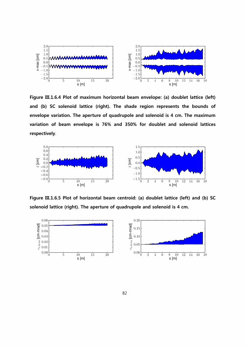
82
Figure III.1.6.4 Plot of maximum horizontal beam envelope: (a) doublet lattice (left)
and (b) SC solenoid lattice (right). The shade region represents the bounds of
envelope variation. The aperture of quadrupole and solenoid is 4 cm. The maximum
variation of beam envelope is 76% and 350% for doublet and solenoid lattices
respectively.
Figure III.1.6.5 Plot of horizontal beam centroid: (a) doublet lattice (left) and (b) SC
solenoid lattice (right). The aperture of quadrupole and solenoid is 4 cm.

83
Figure III.1.6.6 Plot of horizontal rms emittance: a) doublet lattice (left) and (b) SC
solenoid lattice (right). The maximum increases of rms emittance are 10% and 140%
for doublet and solenoid lattices respectively.
Figure III.1.6.7 Plot of longitudinal rms emittance: a) doublet lattice (left) and (b) SC
solenoid lattice (right). The maximum increases of rms emittance are 40% and 50%
for doublet and solenoid lattices respectively.
[References-III.1.6]
[III.1.6-1] S. Nath et al., ASAC Review presentation, October 2001, SNS/ORNL, Tennessee.,
USA
III.1.7 Beam Diagnostics and Collimation
For the previous design, beam diagnostics can be installed only at the limited places,
namely the joints between long cryomodules. This is a very serious limitation in light of
beam operation such as establishing matching between different segments of the SCL for
the high intensity beam operation.
On the contrary, the beam box located at every doublet is reserved for various
diagnostics devices such as beam profile monitors, beam current monitors (BCM),
Faraday cups, emittance scanners, bunch shape monitors (BSM), etc. Beam position

84
monitors (BPM) will be installed with quadrupoles, providing beam position and phase
data. This feature is a very strong merit in light of beam diagnostics for beam operation
and commissioning. Compared with the previous design, there are beam boxes regularly
placed for necessary beam diagnostics and this is critical for operation and accurate
machine tuning. For instance four profile monitors installed in series can easily establish
matching [III.1.7-1]. Because the beam box is in the warm section, maintenance and
alignment are straightforward.
One of the challenges of the driver SCL beam diagnostics systems is to detect and
measure beam parameters for a wide range of beam intensities. This can be
accommodated through proper design of beam boxes and beam diagnostics. Necessary
beam diagnostics for high intensity beam tuning are beam profile monitors, BPMs, beam
loss monitors, emittance scanners, BCMs, Faraday Cup etc. Figure III.1.7.1 shows a
preliminary beam diagnostics configuration of the driver SCL. For the charge stripping
station, required beam diagnostics are BPMs, beam profile monitors, BCMs, and beam
loss monitors, etc.
Figure III.1.7.1 Schematic plot of beam diagnostics configuration of the driver SCL.
Here are included BCM (Beam Current Monitor), BPM (Beam Position Monitor), PM
(Profile Monitor), BLM (Beam Loss Monitor), FC (Faraday Cup) etc.
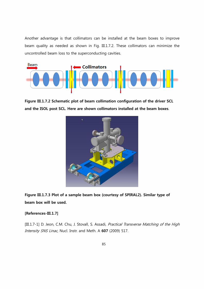
85
Another advantage is that collimators can be installed at the beam boxes to improve
beam quality as needed as shown in Fig. III.1.7.2. These collimators can minimize the
uncontrolled beam loss to the superconducting cavities.
Figure III.1.7.2 Schematic plot of beam collimation configuration of the driver SCL
and the ISOL post SCL. Here are shown collimators installed at the beam boxes.
Figure III.1.7.3 Plot of a sample beam box (courtesy of SPIRAL2). Similar type of
beam box will be used.
[References-III.1.7]
[III.1.7-1] D. Jeon, C.M. Chu, J. Stovall, S. Assadi, Practical Transverse Matching of the High
Intensity SNS Linac, Nucl. Instr. and Meth. A 607 (2009) 517.

86
III.1.8 Superconducting RF and Magnet Test Facility
Figure III.1.8.1: Layout of the temporary Superconducting RF Test Facility.
Considering the possible delay in procuring the site, a contingency plan for the
temporary Superconducting RF and Magnet Test Facility is being developed. Cost of the
superconducting RF Test Facility is estimated to be \2856 M (excluding cryogenic
system). And the facility includes cavity chemical process unit for EP processing and BCP
processing, RF test stand, RF systems, class 10 and class 100 clean rooms, two vertical
test cryostats, vacuum furnace, etc. Scrubbers and chemical storage space are not
included in the layout drawing of Figure III.1.8.1. A space required for the temporary
Superconducting RF Facility is about 50 m x 25 m. The plan for the Magnet Test Facility is

87
developed and its cost is estimated to be \1200 M with required space 20 m x 20 m.
The Cryomodule Test Bunker can be added as needed depending on the construction
schedule of test facilities on site and its cost is not included in the cost estimation given
above. Also we are developing a plan for the permanent Superconducting RF Facility to
be built on site and cost estimation is developed.

88
III.1.9 Engineering Design and Fabrication of Superconducting Cavities
Pure Nb with about 3 mm thickness and RRR > 300 will be used for the construction of
the superconducting cavities. Mechanical design aspects, multipacting analysis, and
thermal analysis will be conducted for the prototyping of superconducting cavities. As
the engineering design is completed, superconducting cavities will be prototyped and
mass produced. Figure III.1.9.1 shows the flow chart of the SC cavity fabrication and
processing and Fig. III.1.9.2. the flow chart of SC cavity and cryomodule design,
fabrication and test procedures
Figure III.1.9.1. Flow chart of SC cavity fabrication and Processing
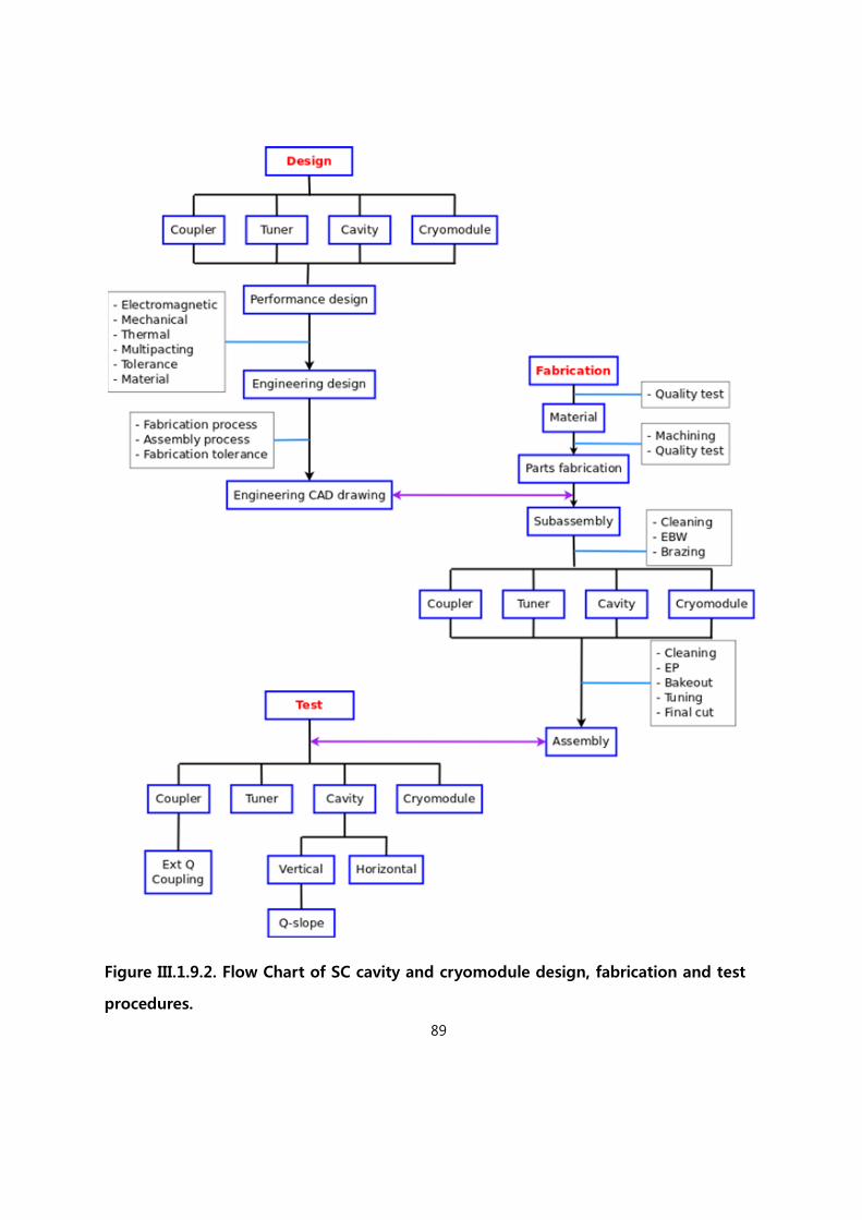
89
Figure III.1.9.2. Flow Chart of SC cavity and cryomodule design, fabrication and test
procedures.
90
A property of niobium sheet has been carefully chosen in order to achieve the cavity
parameters as shown in Table III.1.5.2. The RRR (Residual Resistance Ratio) should be
larger than 300. The grain size is about 64 of ASTME5. The property of niobium sheet is
listed in Table. III.1.9.1. Thickness of niobium sheet is chosen as 3 mm to keep mechanical
stability and to facilitate fabrication process.
Table. III.1.9.1 Properties of niobium sheet
RRR
Tensor
Strength
(MPa)
Yield
Strength
(MPa)
Elongation
(%)
Vickers
Hardness
(HV)
Grain Size
> 300 > 96.4 48.2 < Rp
> 40 LD
> 35 TD
< 50 (Hv10)
< 64 (ASTM5)
< 90 (ASTM4)
III.1.9.1 Tolerance Analysis
Tolerance analysis related with the fabrication is to be done for the superconducting
cavities. Its impact on the parameters of the cavities will be analyzed.
The tolerance on superconducting cavity fabrication shall be minimized, for an example,
a minimum tolerance 0.02 mm is considered. Since the cavity fabrication consists of a
variety of fabrication process, a fabrication tolerance should be minimized at each
fabrication step. The fabrication process should be standardized in order to estimate the
tolerance as well. The bandwidth of superconducting cavity is around 40 Hz after
applying slow and fast tuners during normal operation. Table III.1.9.2 shows the change
of resonant frequency of superconducting cavity which is induced by cavity fabrication
and processing, for example, of quarter waver resonator.

91
Table. III.1.9.2 Effect of cavity fabrication and processing on resonant frequency for
QWR [Ref III.1.9.1].
Process Value Comment
Cavity length(upper) -132 kHz/mm
Frequency shift by length of
center conductor and upper
end
Cavity length(lower) +30 kHz/mm Frequency shift by length of
lower end
Welding +59 kHz 0.58mm shrink/weld
EP +238 kHz 125um base, 187um @ DT
& Nose
Vacuum +23 kHz 1 ATM 10-7 torr
Cool down +156 kHz 293K 4K
L-He pressure 10s Hz/torr Fluctuation of L-He
Lorentz Detuning ~0.1 Hz/(MV/m)2
Deforming of cavity by
Lorentz force
(MSU, β=0.041)
[Reference III.1.9]
[III.1.9.1] G. P. Zinkann et. al., Proceedings of HIAT09, p.156, 2009

92
III.1.9.2 Mechanical Design
Mechanical characteristics of the superconducting cavities will be analyzed using the CST
and ANSYS codes to study and to ensure that the cavity design meets the requirement
of Lorentz force detuning, detuning due to helium pressure fluctuation (df/dP),
microphonics detuning etc. EM design has been conducted to reduce Bpeak and Epeak
which in turn reduces the Lorentz force detuning. Stiffening the cavity endwalls and shell
reduces the Lorentz force detuning and detuning due to helium pressure fluctuation.
Endwalls of spoke resonators are reinforced with two types of ribs: donut ribs and daisy
ribs. The design of the helium jacket is to be studied in light of the df/dP characteristics.
Figure III.1.9.1 Plot of reinforcing ribs (Courtesy of FNAL)
III.1.9.3 Multipacting Analysis
It is important to avoid multipacting barriers as much as possible and the design should
be optimized by using the CST electron tracking code. Multipacting analysis will be
conducted for the combined structure of the cavity and power coupler.
III.1.9.4 Thermal Analysis
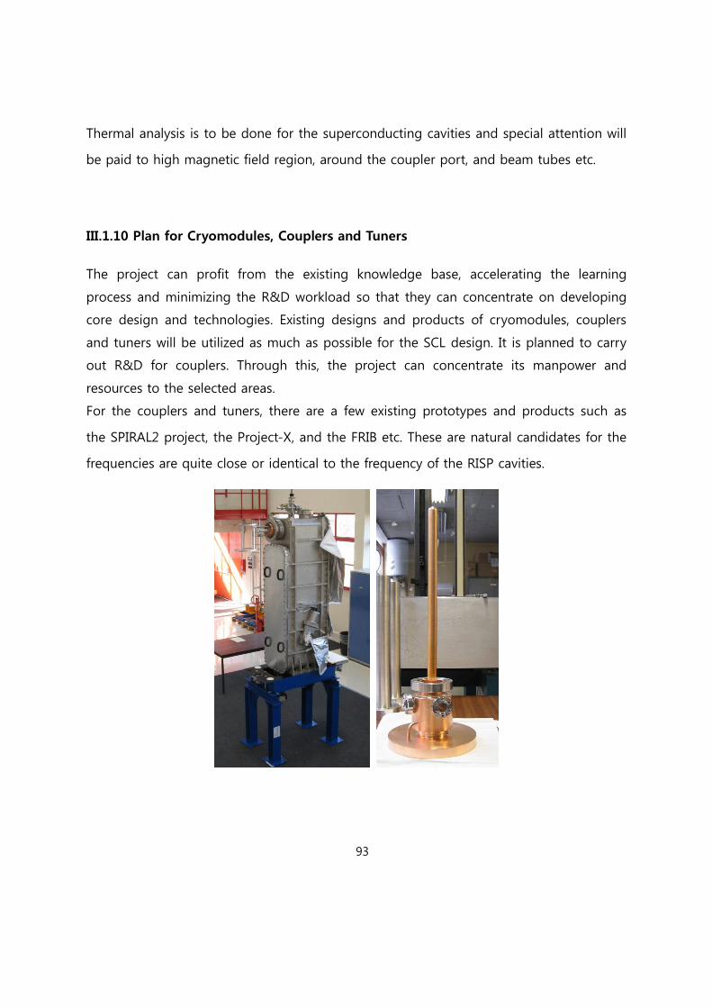
93
Thermal analysis is to be done for the superconducting cavities and special attention will
be paid to high magnetic field region, around the coupler port, and beam tubes etc.
III.1.10 Plan for Cryomodules, Couplers and Tuners
The project can profit from the existing knowledge base, accelerating the learning
process and minimizing the R&D workload so that they can concentrate on developing
core design and technologies. Existing designs and products of cryomodules, couplers
and tuners will be utilized as much as possible for the SCL design. It is planned to carry
out R&D for couplers. Through this, the project can concentrate its manpower and
resources to the selected areas.
For the couplers and tuners, there are a few existing prototypes and products such as
the SPIRAL2 project, the Project-X, and the FRIB etc. These are natural candidates for the
frequencies are quite close or identical to the frequency of the RISP cavities.

94
Figure III.1.10.1 Photograph of the SPIRAL2 low-beta cryomodule that contains one
cavity (the left plot) and the coupler (the right plot). This type of cryomodule and
power coupler can be adopted for the RISP SCL1. (Courtesy of the SPIRAL2)
For cryomodules, the SCL1 section cryomodule design will benchmark/adopt the SPIRAL2
design and the SCL2 section cryomodule design can adopt the FNAL Project-X
cryomodule design or ILC cryomodule design.
Figure III.1.10.2. Plot of the tuner with the cavity (Courtesy of the EURISOL).

95
Figure III.1.10.3. Plot of the FNAL cryomodule (Courtesy of the FNAL). This type of
cryomodule can be adopted for the SCL2 cryomodules.
III.1.11 RF System
The accelerator facility is composed of some accelerator devices such as super
conducting cavities for linear accelerator. All these devices accelerate the RI beam by the
RF field in the cavity provided by the RF amplifiers. The RF field in the cavity might be
fluctuated by the various reasons such as resonance frequency change, temperature
variation, helium pressure change, beam current etc. RF systems not only supply RF
power for superconducting cavities but also control SC Linac system in order to acquire
the good beam stability. Figure III.1.11.1 shows schematic diagram the RF system about
RISP. The operating base RF frequency is 81.25 MHz for the QWR, 162.5 MHz for HWR
and 325 MHz for the SSR1 and SSR2. The stability of the RF field should be within ±1%
in amplitude and ±1° in phase, and the resonant frequency control is required. The
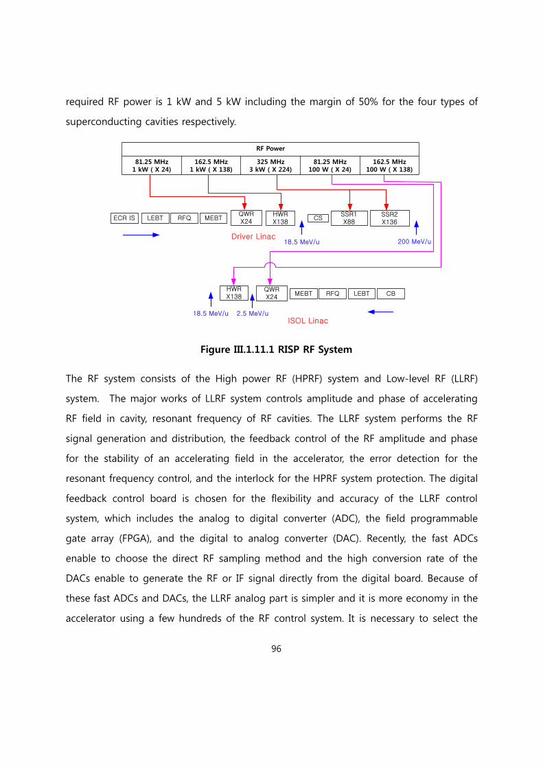
96
required RF power is 1 kW and 5 kW including the margin of 50% for the four types of
superconducting cavities respectively.
ECR IS MEBTRFQQWRX24
HWRX138
CSLEBTSSR1X88
SSR2X136
18.5 MeV/u 200 MeV/uDriver Linac
QWRX24
HWRX138 CBLEBTRFQMEBT
2.5 MeV/u18.5 MeV/uISOL Linac
RF Power
81.25 MHz1 kW ( X 24)
162.5 MHz1 kW ( X 138)
325 MHz3 kW ( X 224)
81.25 MHz100 W ( X 24)
162.5 MHz100 W ( X 138)
Figure III.1.11.1 RISP RF System
The RF system consists of the High power RF (HPRF) system and Low-level RF (LLRF)
system. The major works of LLRF system controls amplitude and phase of accelerating
RF field in cavity, resonant frequency of RF cavities. The LLRF system performs the RF
signal generation and distribution, the feedback control of the RF amplitude and phase
for the stability of an accelerating field in the accelerator, the error detection for the
resonant frequency control, and the interlock for the HPRF system protection. The digital
feedback control board is chosen for the flexibility and accuracy of the LLRF control
system, which includes the analog to digital converter (ADC), the field programmable
gate array (FPGA), and the digital to analog converter (DAC). Recently, the fast ADCs
enable to choose the direct RF sampling method and the high conversion rate of the
DACs enable to generate the RF or IF signal directly from the digital board. Because of
these fast ADCs and DACs, the LLRF analog part is simpler and it is more economy in the
accelerator using a few hundreds of the RF control system. It is necessary to select the

97
ADCs with the small aperture jitter for the low phase noise in the direct RF sampling
using the high sampling clock. The FPGA is chosen to process quickly the digital signal
of the in-phase (I) and the quadrature-phase (Q) from the ADCs. The IQ signal of the RF
amplitude and phase from the cavity is controlled by the control logic programmed with
the PI algorism in the FPGA.
The HPRF system transmits the high-power RF signal to the cavity and must be
protected from the arc and high reflected RF power. The HPRF system includes the high
power amplifier, the isolator, the RF transmission line and the high power components.
The high power amplifier and high power components are designed according to the RF
power level and the operating frequency.
Figure III.1.11.2 shows the conceptual block diagram for the LLRF control system. The
operating RF frequency is 81.25 MHz for the QWR, 162.5 MHz for the HWR and 325
MHz for the SSR1 and SSR2. According to the current technologies of the ADCs and
DACs, the direct RF sampling and the direct RF generation in the digital FPGA module
can be chosen for the digital feedback control. For the direct RF sampling, the sampling
clock frequency is determined to 56 MHz clock for the 81.25 MHz RF signal and 224
MHz clock for the 325 MHz RF signal by using the IQ sampling method of every 450
degree phase. It is necessary to select the ADCs with the small aperture jitter for the low
phase noise in the high 224MHz sampling clock. The sampling clock signal of 224MHz is
distributed from the RF reference line. The RF signal of 81.25 MHz and 325 MHz is also
generated directly from the digital module and is transmitted to the cavity through the
HPRF system. In this LLRF control system, the LO signal and IF signal used for the
heterodyne system are not needed to use for the feedback control. Because of the direct
RF sampling and the direct RF generation in the digital module, the analog part of the
LLRF control system is simpler and it is more economy in this accelerator using a few
hundreds of the RF control system. The forward (FWD) RF signal, the backward(BWD) RF
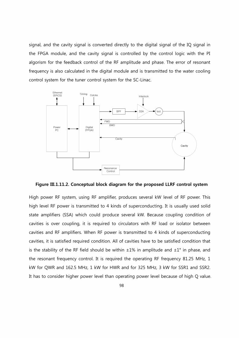
98
signal, and the cavity signal is converted directly to the digital signal of the IQ signal in
the FPGA module, and the cavity signal is controlled by the control logic with the PI
algorism for the feedback control of the RF amplitude and phase. The error of resonant
frequency is also calculated in the digital module and is transmitted to the water cooling
control system for the tuner control system for the SC-Linac.
PowerPC
Digital(FPGA)
Cavity
Resonance Control
Ethernet(EPICS)
Timing Colcks
BPF SSA Isol.
FWD
BWD
Cavity
Interlock
Figure III.1.11.2. Conceptual block diagram for the proposed LLRF control system
High power RF system, using RF amplifier, produces several kW level of RF power. This
high level RF power is transmitted to 4 kinds of superconducting. It is usually used solid
state amplifiers (SSA) which could produce several kW. Because coupling condition of
cavities is over coupling, it is required to circulators with RF load or isolator between
cavities and RF amplifiers. When RF power is transmitted to 4 kinds of superconducting
cavities, it is satisfied required condition. All of cavities have to be satisfied condition that
is the stability of the RF field should be within ±1% in amplitude and ±1° in phase, and
the resonant frequency control. It is required the operating RF frequency 81.25 MHz, 1
kW for QWR and 162.5 MHz, 1 kW for HWR and for 325 MHz, 3 kW for SSR1 and SSR2.
It has to consider higher power level than operating power level because of high Q value.

99
The HPRF system is designed with the operating RF frequency and the RF power rating.
The HPRF system supply RF power for cavities of superconducting CW Linac. Figure
III.1.11.3 shows the conceptual block diagram for the SC-Linac HPRF system. A solid-state
RF amplifier drive a SC-Linac, and a circulator and a RF dummy load are installed to
absorb the reflected RF power from the SC-Linac in order to protect SSA.
Figure III.1.11.3. Conceptual block diagram for the SC-Linac HPRF system
In order to transmit RF to the SC cavities, we usually used rigid coaxial line considering
handling power and attenuation per unit length. Figure III.1.11.4 shows rigid coaxial line
which is fabricated by MEGA cooperation. It is obtained by utilizing high conductivity
copper inner conductors that are supported by Teflon insulators. The outer conductors
are precision drawn heavy wall copper tubing.
Figure III.1.11.4. Picture of rigid coaxial line (MEGA Company).

100
Figure III.1.11.5 and III.1.11.6 shows the RF handing power and attenuation of rigid
coaxial line, respectively. 1-5/8” rigid coaxial line are available the transmission line
between SSA and SC cavities Attenuation of coaxial line per 100 ft is maximum 0.3 dB.
Figure III.1.11.5. Graph of coaxial line power handling.
Figure III.1.11.6. Graph of coaxial line attenuation.
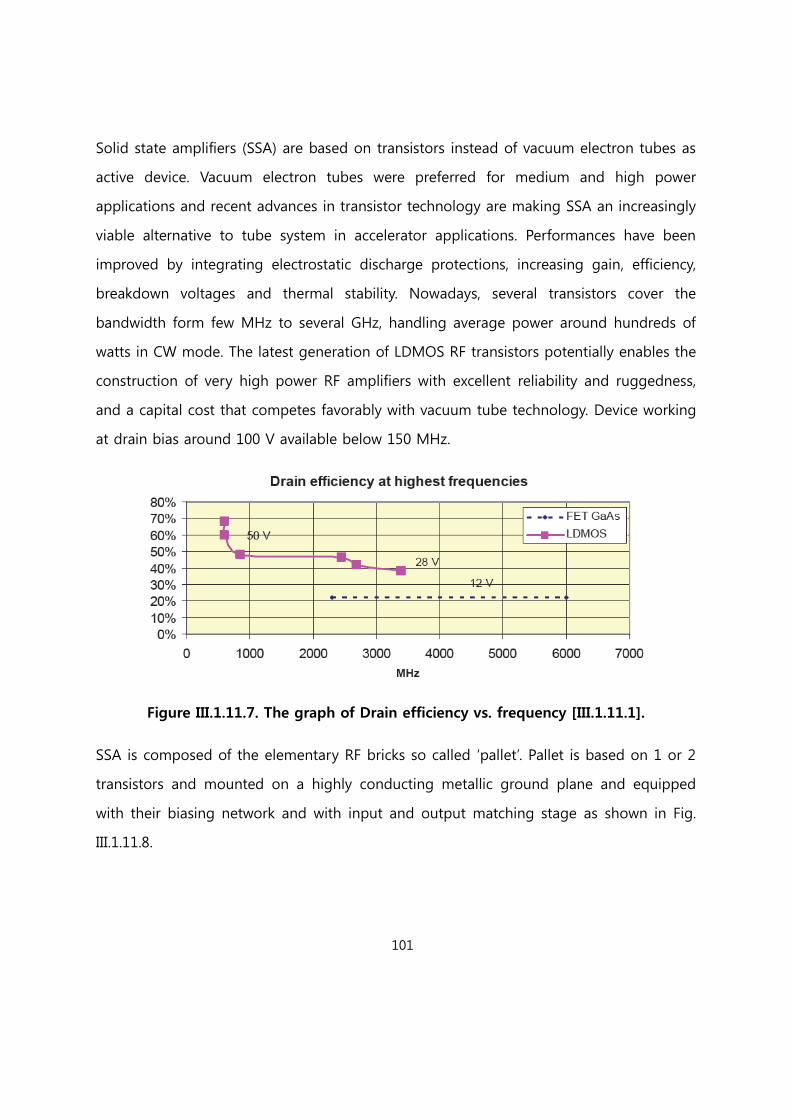
101
Solid state amplifiers (SSA) are based on transistors instead of vacuum electron tubes as
active device. Vacuum electron tubes were preferred for medium and high power
applications and recent advances in transistor technology are making SSA an increasingly
viable alternative to tube system in accelerator applications. Performances have been
improved by integrating electrostatic discharge protections, increasing gain, efficiency,
breakdown voltages and thermal stability. Nowadays, several transistors cover the
bandwidth form few MHz to several GHz, handling average power around hundreds of
watts in CW mode. The latest generation of LDMOS RF transistors potentially enables the
construction of very high power RF amplifiers with excellent reliability and ruggedness,
and a capital cost that competes favorably with vacuum tube technology. Device working
at drain bias around 100 V available below 150 MHz.
Figure III.1.11.7. The graph of Drain efficiency vs. frequency [III.1.11.1].
SSA is composed of the elementary RF bricks so called ‘pallet’. Pallet is based on 1 or 2
transistors and mounted on a highly conducting metallic ground plane and equipped
with their biasing network and with input and output matching stage as shown in Fig.
III.1.11.8.

102
RF MOSFET
Input matching
stage
Output matching
stage
Controland
ProtectionsBias Circult
Figure III.1.11.8. Typical pallet block diagram.
Figure III.1.11.12 shows 800 W pallet, is based on 2 transistors, having 88 to 108 MHz
frequency (©DB ELETTRONICA).
Several of pallets are then combined together to obtain higher output power. Isolated
dividers and coupler can be used to avoid oscillations or other phenomena which could
bring to the transistor destruction. Circulator or isolators can also be used to decouple
each amplifier, making it unconditionally stable, and in this case non isolated
splitter/combiners can be used. Splitters, combiners and circulators are therefore
extremely important elements of solid state RF amplifier. At very low frequencies,
circulators can’t be used and transistors are operated at around 50% of their possibilities.
In case of failure of a few transistors, the solid state architecture grants significant
amount of power being still possible to replace the broken module without interrupting
the amplifier operation.

103
Figure III.1.11.9. The picture of 800 MW pallet frequency (©DB ELETTRONICA)
Figure III.1.11.10 shows schematic of which several of pallets (800 W) are then combined
together to obtain 5 kW output power. Isolated dividers and coupler can be used to
avoid oscillations or other phenomena which could bring to the transistor destruction.
Circulator or isolators can also be used to decouple each amplifier, making it
unconditionally stable, and in this case non isolated splitter/combiners can be used.
Splitters, combiners and circulators are therefore extremely important elements of solid
state RF amplifier. In principle power combiners become splitters when used backward.
Isolated splitter is usually used Gysel type rather than Wilkinson type at high power. The
Gysel scheme is largely used for N-way splitters or combiners in 80 to 200 MHz range of
frequency. Circulators or isolators are used when the signal coming back is deviated on a
dummy load. This is the configuration used in solid state amplifiers to protect the
transistor or all the amplifier devices against reflected power. Isolators have to be
disposed between pallets and combiner, because it can be required more high level RF
power for SCL cavities to have high Q value.

104
Splitter
LO
P1
P2
P3
P4
P5
P6
P7
P8
C
C
C
C
C
C
C
C
Combiner
Figure III.1.11.10. Possible combining schematic for 5 kW SSA
[Reference III.1.11]
[III.1.11.1] Marco Di Giacomo Solid state RF amplifiers for accelerator applications, PAC09,
Canada (2009)

105
III.1.12 Control System
The RISP Accelerator Control System (RiCS), shown in Figure III.1.12.1, has the
omnipotent policy of standardization. The strict standardization is absolutely essential to
mitigate the integration risk. If we do not follow this policy, the risk will ask the RISP for
prohibitively expensive efforts with respect to money, time, and man-power, because of
the complexity of the RISP accelerator. And this term of the standardization gives a
guarantee so that we can extend and upgrade existent all software and hardware
equipment later. Thus, to pursuit the strict standardization is indispensable for the
scalability of RiCS.
Moreover, we would like to build the maximum security control system for the RISP,
because much more control equipment are going to be online within private, public
networks, and both and many users and operators use their online devices in order to
access valuable information from whole control system network. The security system
will be the challenges of the next few years, especially, when the RISP accelerator will be
being operated, because we cannot predict how complicated network environment will
be due to its evolution speed.
For the cost-effective integration and scalability, a modular block system will be designed
based on an abstract object-oriented device with standardized interfaces. Therefore a
modular block can communicate with other blocks, can be integrated into others blocks
as a sub-block, and can be extended into new blocks easily.
106
Figure III.1.12.1. Conceptual Architecture of the RISP Control System (RiCS). In the
drawing, SCL stands for Superconducting Linac, PostA does Post-Accelerator, RF does
Radio Frequency system, and so on. End user represents who wants to check or monitor
the RISP control system passively and Operator does the system actively. DAQ represents
Data Acquisition. The experimental control/DAQ systems can communicate with RiCS.
III.1.12.1 Requirements
The RISP control system (RiCS) should be reliable, scalable, maintainable, and low-cost
system that could be used easily and fun by end-users and operators. Therefore the
Experimental Physics and Industrial Control System (EPICS) is selected as an infrastructure
for RiCS, because it is reliable, scalable, maintainable, low-cost system, and standard.
EPICS is an open-source, i.e. the source code is accessible, software that has various tools,
libraries, and predefined applications developed by a world-wide user community and is
used in large and small experimental physics projects such as particles accelerators,
telescopes, and light sources since 1994. In addition, EPICS supports several hundred
different modules with almost all bus types that produced by more than hundred
manufacturers. Especially, in South Korea, EPICS is the crucial infrastructure at the
Pohang Accelerator Laboratory (PAL) and Korea Superconducting Tokamak Advanced
Research (KSTAR). As a result, RISP will benefit from PAL and KSTAR that have already
done a huge contribution to EPICS community in South Korea.
The main operating system (OS) is selected as Linux, because it also fulfills the control
system design goal, i.e. reliable, scalable, maintainable, and low-cost. In addition, Linux is
open-source software and has almost no malicious softwares to compare with other OSs,
especially Windows series. Two Linux systems are considering now; Debian and Red Hat
Enterprise Linux (RHEL). Debian system is a complete free OS and RHEL is also a free OS,

107
but has commercial supports. Debian is a better choice than RHEL according to the cost
of OS itself in the long term, but Debian Linux experts must be recruited at the early
stage in order to maintain OS itself. For RHEL, Linux OS experts are not mandatory,
because of Red Hat customer supports.
Here some important requirements which RiCS must fulfill are itemized as follows:
RiCS could read, change, and record all raw signals from all equipment of the
accelerator and all logic signals generated by some raw signals.
RiCS could provide an effective user interface, e.g. graphical users interface (GUI),
so that users can access any recorded signal easily.
RiCS could record standard procedure for running up the accelerator and related
configuration for all equipment.
RiCS could provide automatic procedure for running up the accelerator
according to preset conditions.
RiCS could provide the continuous optimization of all equipment during the
accelerator running.
RiCS could oversee all equipment, alert operators, end-users, or both to fault
conditions, and could provide tools in order to analyze any fault quickly.
A control system of a device could be a member of other integrated control
system and could be one component of RiCS.
III.1.12.2 Abstract Concept of a Basis
Figure III.1.12.2 shows an abstract concept of a basis for RiCS, within the EPICS
framework, which could be divided into three modular blocks as follows: Application
Block, Service Block, and Resource Block. Three modular blocks are divided according to
each key role. In reality, however, each block has similar components that exist in other
block.
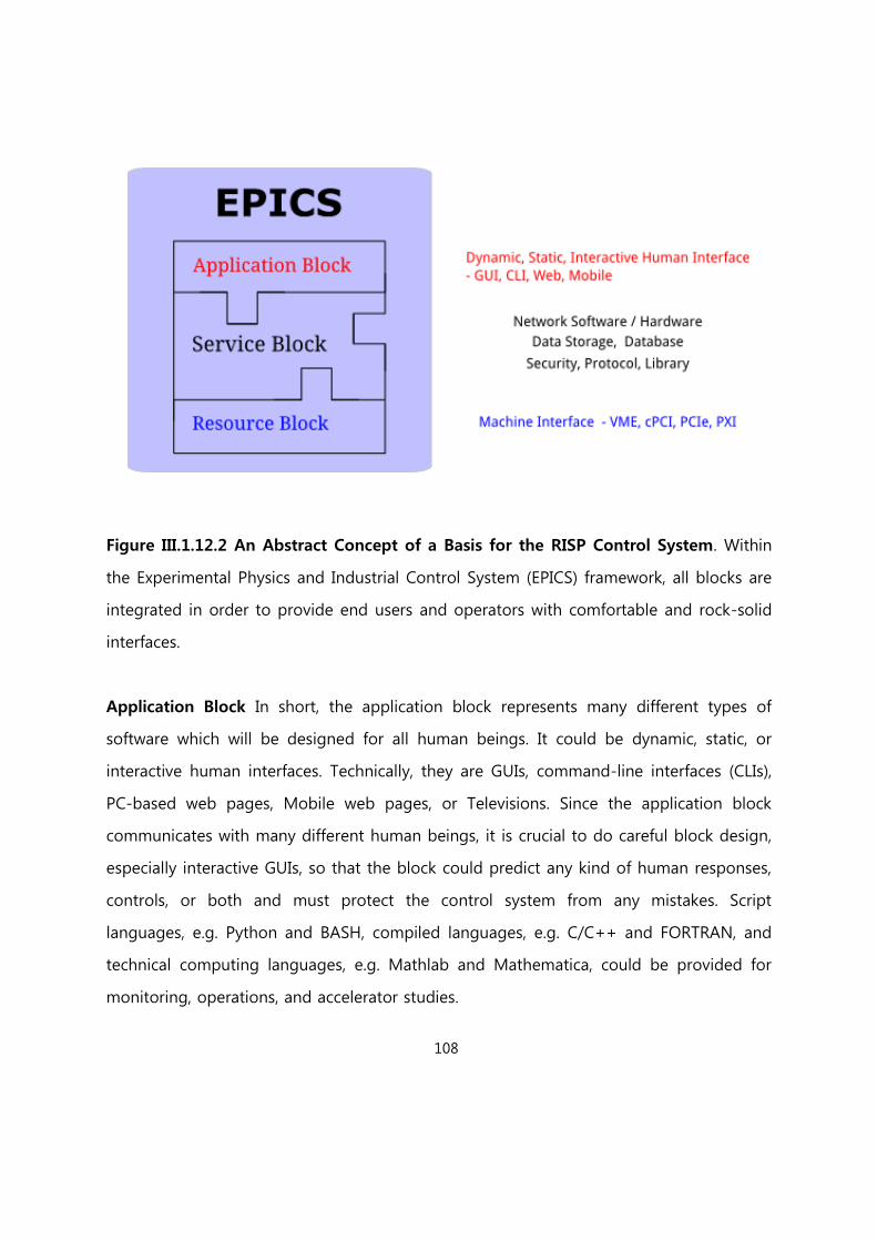
108
Figure III.1.12.2 An Abstract Concept of a Basis for the RISP Control System. Within
the Experimental Physics and Industrial Control System (EPICS) framework, all blocks are
integrated in order to provide end users and operators with comfortable and rock-solid
interfaces.
Application Block In short, the application block represents many different types of
software which will be designed for all human beings. It could be dynamic, static, or
interactive human interfaces. Technically, they are GUIs, command-line interfaces (CLIs),
PC-based web pages, Mobile web pages, or Televisions. Since the application block
communicates with many different human beings, it is crucial to do careful block design,
especially interactive GUIs, so that the block could predict any kind of human responses,
controls, or both and must protect the control system from any mistakes. Script
languages, e.g. Python and BASH, compiled languages, e.g. C/C++ and FORTRAN, and
technical computing languages, e.g. Mathlab and Mathematica, could be provided for
monitoring, operations, and accelerator studies.
109
Resource Block The resource block represents many different types of hardware
designed for all machine interfaces and most interesting information which we want to
monitor, control, or both. Technically, it also contains software in order to send and
receive all information between the service block and the resource block. International
standards such as VME, cPCI, PCIe, and PXI as the interfaces must be selected in order to
upgrade and maintain them later without any difficulty.
Service Block The service block covers a broad range of hardware devices, for example,
computers for simulation and analysis, operators consoles, databases, network switches,
gateways, and backbones, displays, e.g. TVs and monitors, data storage, uninterruptible
power supplies, port-servers, remote-access power distribution units, and so on. In
addition, all configuration files, libraries, and software for all hardware devices are
included in the service block. This block must be designed to share any kind of a basis
information with other systems, e.g. Machine Protection System, Human Protection
System, Timing System, and Experimental Control / DAQ systems, because it is one basis
of RiCS.
III.1.12.3 Operation Designs
From the operation point of view, the control system is divided into three separated, but
integrated, designs: Stand alone, Operation, and Debug. Each design shares its
functionality with others or itself and can be easily integrated into others or itself
according to a place where it is used.
Stand-alone Design A compact and modularized system, that has three basis blocks,
i.e. Application, Resource, and Service blocks, could be used as stand-alone system
especially during testing on a prototype of any equipment of the accelerator. Simple,
110
intuitive, and self-descriptive interfaces should be considered for developing GUIs and
CLIs. By using these interfaces, low level hardware accesses could be possible. This
design is a basic single component of the RiCS, and could be integrated into the other
components, the central control system, or both. Figure III.1.12.3 shows the stand alone
design in the first row. Four elements, i.e. hardware, a database manager, an operator or
end-user interface, and an expert interface, connect with each other via Ethernet, and
should have a standard interface in order to connect to Ethernet and others, e.g. RS-232
connection, according to their purposes. The GUI and CLI should read, set, and monitor
any signals
Operation Design A simple and easy-to-use system, that has three basis blocks, could
be used for accelerator operators and for various end-users. The accelerator operators
actually operate the accelerator and monitor or change its configuration while running
up. So this system should provide a collection of tools for monitoring, alarm handling,
and logging. Moreover, standard procedure for running up the accelerator and related
configuration for all equipment could be saved into database systems automatically.
These saved entries in the databases could be used in the restoration of the preset
accelerator configuration and in the further investigation of the accelerator equipment.
End-users want to see, save, monitor, and re-use any kind of information form the
accelerator on the basis of time with their interest. Figure III.1.12.3 shows the operation
design in the second row. This design excludes end-users and operators from expert
interfaces. However, these excluded expert interfaces could be accessible via an expert
mode when it is necessary. And it includes feedback systems that might be needed to
optimize devices into desired accelerator operation.

111
Figure III.1.12.3 Left dot-lined boxes show the three Operation designs.
Set/Read/Monitor is an operational functionality that operators or end-users could set,
read, and monitor any signal from a system. Alarm is an integrated tool within GUI and
CLI and could alert operators or users. Log/DB represents database related software and
hardware that are under DB manager. Hardware does any kind of hardware device which
could accept raw signals.

112
Debug Design A modularized and portable system, which has three basis blocks, could
be used for experts who are interested in understanding, debugging, and
troubleshooting any device that is identified as a bad or malfunctioning one. It should
provide a cost-effective way to experts in order to find reasons for any malfunction and
to do a quick recovery. It might be one subsystem of an operator interface, a stand-
alone system, or both. Sometimes, a malfunctioning system or device cannot be
accessible remotely, so experts have to recover the non-accessible system via a direct
connection. Therefore, portability is essential. Figure III.1.12.3 shows the debug design in
the third row.
III.1.12.4 Safety System
Safety system is an integrated part of the control system and consists of Personnel
Protection System (PPS) and Machine Protection System (MPS).
III.1.12.4.1 Personnel Protection System (PPS)
The PPS protects personnel from the radiation and other hazards caused by the
operation of the accelerators and its subsystems. As the PPS assures the safety of people,
it should be highly reliable and failure-proof. The system makes use of Programmable
Logic Controllers (PLCs). Usual computers are not used in the interlock sequence because
their limited reliability. They are used only in software development and monitoring of
PLCs. The PPS is isolated from other systems, such as the accelerator control system, to
prevent it from being disturbed. In order to make the system reliable, PLCs are installed
redundantly. The signals of important devices, such as emergency buttons, door switches,
etc., are also redundantly read. Metal wires are used to connect these devices to PLCs in
a local control room. The central control room and local control rooms are connected
with both of optical fibers and metal wires.

113
III.1.12.4.1.1 Interlocks
We will have at least two levels of interlock. In case of the level 1 interlock (emergency
button, door interlock, etc.):
the ion source is interlocked off,
three beam stops in LEBT and MEBT are inserted,
the safety bending magnets for the interlocked area are turned off,
high power equipment of the area are turned off.
In case of the level 2 interlock (radiation monitor interlock, etc.):
one or two beam stops in the LEBT and/or MEBT are inserted into the beam line.
III.1.12.4.2 Machine Protection System (MPS)
Machine Protection System (MPS) is to protect the accelerator system against equipment
failure and excessive beam losses, depending on the operational mode of the accelerator
and the beam dump in use. This system is tightly integrated with the timing system. The
MPS uses the timing system to assure operation within specified parameters. In addition,
information on shut-down causes originating with the MPS is broadcast by the timing
system for post mortem analysis. The main functions of the MPS are as follows:
Protect the beam tubes and insertion devices (slits, Faraday cups, targets, etc)
from beam thermal damages,
Control the operating range of the facility,
Control the accelerator device activation due to beam losses (beam losses limited
to 1W/m),
Ensure protection of the beam dumps and targets.
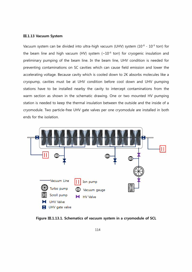
114
III.1.13 Vacuum System
Vacuum system can be divided into ultra-high vacuum (UHV) system (10-8 - 10-9 torr) for
the beam line and high vacuum (HV) system (~10-6 torr) for cryogenic insulation and
preliminary pumping of the beam line. In the beam line, UHV condition is needed for
preventing contaminations on SC cavities which can cause field emission and lower the
accelerating voltage. Because cavity which is cooled down to 2K absorbs molecules like a
cryopump, cavities must be at UHV condition before cool down and UHV pumping
stations have to be installed nearby the cavity to intercept contaminations from the
warm section as shown in the schematic drawing. One or two mounted HV pumping
station is needed to keep the thermal insulation between the outside and the inside of a
cryomodule. Two particle-free UHV gate valves per one cryomodule are installed in both
ends for the isolation.
Figure III.1.13.1. Schematics of vacuum system in a cryomodule of SCL

115
III.1.13.1. HV System
A HV pumping station consists of an oil-free scroll pump for a backing pump, a turbo
molecular pump (TMP) for high vacuum generation, a full-range cold cathode type
vacuum gauge, and HV valves. In the case of backing pump, the pumping speed is
around 500Liters/minute and the ultimate vacuum level is high 10-3 torr. After the
vacuum level of low 10-2 torr is attained using the backing pump, the TMP starts up and
generates vacuum until 10-6 torr ~ 10-7 torr. The TMP of ~1,000 Liters/sec pumping
speed is adopted in consideration of the efficient vacuum generation and the cost
effectiveness. The full range vacuum gauges which can measure the vacuum until 5X10⁻¹⁰
torr are installed in external ports of a cryomodule.
Before cooling the beam line, mobile HV stations are temporally connected preliminary
pumping lines of cavities and mount-type HV stations are installed in a cryomodule
permanently for the thermal isolation. These HV stations are assembled with a
cryomodule in a class 100 clean room. The mobile HV station will be removed from the
preliminary pumping line when the vacuum level of the cavity reaches the 10-9 torr after
cooling. The vacuum level for the thermal insulation is less than 10-5 torr.
Vibration dampers and protections of EM field, etc. are considered in the HV system.
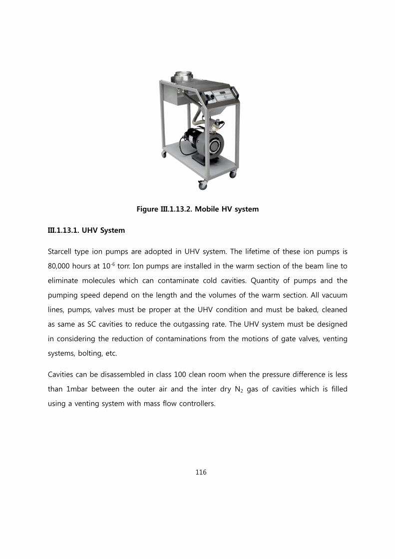
116
Figure III.1.13.2. Mobile HV system
III.1.13.1. UHV System
Starcell type ion pumps are adopted in UHV system. The lifetime of these ion pumps is
80,000 hours at 10-6 torr. Ion pumps are installed in the warm section of the beam line to
eliminate molecules which can contaminate cold cavities. Quantity of pumps and the
pumping speed depend on the length and the volumes of the warm section. All vacuum
lines, pumps, valves must be proper at the UHV condition and must be baked, cleaned
as same as SC cavities to reduce the outgassing rate. The UHV system must be designed
in considering the reduction of contaminations from the motions of gate valves, venting
systems, bolting, etc.
Cavities can be disassembled in class 100 clean room when the pressure difference is less
than 1mbar between the outer air and the inter dry N2 gas of cavities which is filled
using a venting system with mass flow controllers.

117
III.1.14 Accelerator System Installation Plan
SAR (Safety Analysis Report) Review and its related permits are required, for the
construction of accelerator tunnels, buildings, and target areas. SAR Review is a critical
path to the installation of the accelerator systems. As shown in the Fig. III.1.14.1, the SAR
Review ends January 31, 2016 and the construction of the accelerator tunnels is
scheduled to begin February 1, 2016. After allowing minimum time of five months, the
installation of accelerator system is scheduled to start July 1, 2016, including the injector,
the low energy part of the driver SCL, ISOL post accelerator, and cyclotron. For more
details, please refer to the project schedule. Starting the installation of the accelerator
system on July 1, 2016 allows only one and a half years for the installation and the
commissioning, to support the 2017 completion. This presents a very aggressive
schedule.
Figure III.1.14.1 Schedule of the SAR (Safety Analysis Report) ending January 31,
2016.
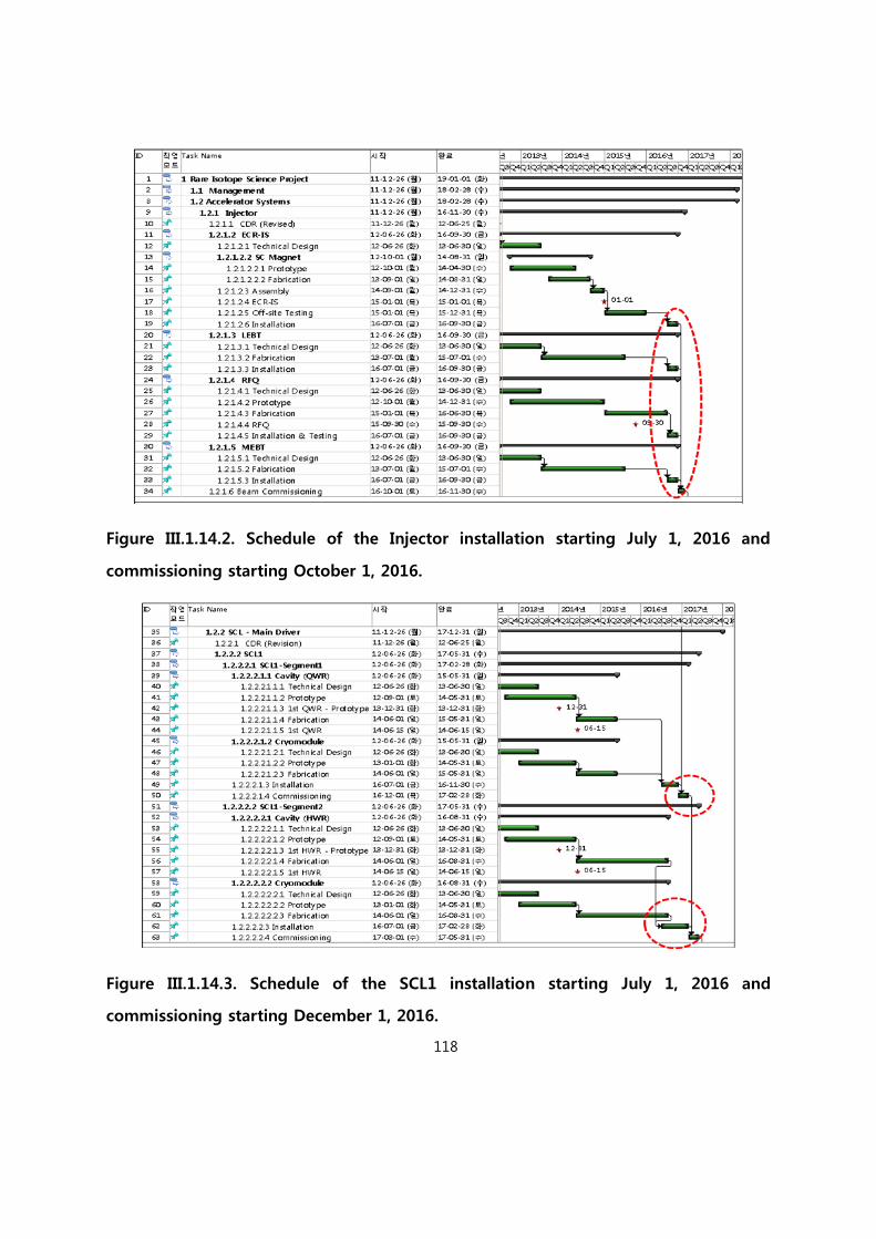
118
Figure III.1.14.2. Schedule of the Injector installation starting July 1, 2016 and
commissioning starting October 1, 2016.
Figure III.1.14.3. Schedule of the SCL1 installation starting July 1, 2016 and
commissioning starting December 1, 2016.

119
III.2 In-Flight Fragment System
The in-flight fragment system consists of pre- and main separators. The pre-separator
includes the target system for the production of rare isotope beams by the mechanisms
of such as projectile fragmentation and in-flight fission. The isotope beam of interest
passes thru the pre-separator, and the remaining beam, which is mostly the primary
beam, needs to be dumped in localized areas. This frond-end of pre-separator including
a target and beam dump should be well shielded from the other regions. All of the parts
will be made in detachable modular form so that any malfunctioning can be repaired by
taking out the affected module to designated repair area. This remote handling will
require careful mechanical design on the joining parts of the modules as they are related
to vacuum sealing and alignment. Modern robot system for remote handling often
heavily uses semiconductor devices, which are weak to radiation damage. Major parts of
the handling system should use metallic components to avoid fast radiation damage. An
efficient approach to the system development would be to adopt established technology
at the high-current beam facility in operation such as the SNS in the US.
A major item requiring development is superconducting quadrupole magnet downstream
of the target in the pre-separator area. This magnet receives the highest level of
radiation dose, and still needs to have a large aperture for large acceptance of isotope
beams. A high-Tc superconducting magnet with warm iron yoke has been developed for
the FRIB project by the BNL group. We will try to develop a similar magnet, and it will be
helpful to collaborate with the BNL group.
We plan to develop superconducting quadrupole magnets for the separator with helps
from domestic companies and laboratories. The superconducting magnets will be of
superferric type, whose field is dominated by iron pole and yoke. A prototype
superconducting cryostat containing a quadrupole magnet triplet with multipole coils
wound on the cold bore tube is planned to be constructed. Magnetic field calculations

120
using OPERA3D have been performed, and will be compared with field mapping results
when the prototype is ready, which will assure the precision of field calculations. The
dipole magnets are planned to be conventional.
III.2.1 RI beam production
The production rate of RI-beams on the in-flight separator system has been calculated.
Momentum and angular dispersions of the 132Sn beam produced by projectile
fragmentation and abrasion fission are shown in Fig. III.2.1.1 as a function of the primary
beam energy.
FigureIII.2.1.1 The momentum and angular dispersions of 132Sn beam produced
from projectile fragmentation (PF) and abrasion fission (AF).
Assuming that angular dispersion of the separator is about 70 mrad in both horizontal
and vertical directions and momentum dispersion accepted is 10%, we calculated all of
rare isotope beams which can be produced from the projectile fragmentation and the
abrasion fission. The results are shown in Fig. III.2.1.2 and Fig. III.2.1.3.

121
Figure III.2.1.2 The production rates of RI-beams by projectile fragmentation
Figure III.2.1.3 The production rates of RI-beams by the abrasion fission.

122
III.2.2 Target
The target for in-flight fragmentation absorbs about 30% of the primary beam power in
average case. The resultant power density inside the target is very high, and thus cooling
is critical. The high-power target for in-flight fragmentation has been numerically studied
using PHITS, which is a heavy-ion radiation transport code to evaluate the generation of
heat and radiation.
The highest power density is calculated to be around 65 MW/cm3 for a U beam of 200
MeV/u at 400 kW, and can be reduced to tens of kW/cm3 by using a rotating target. The
maximum allowable temperature for graphite target is around 1900 C, but temperature
inside the target reaches higher for a single-layer target with a thickness of over 1 mm
for the U beam. A multi-slice target with a thickness in the order of 0.1 mm can reduce
the temperature with enhanced radiation cooling, but then structural problem has been
observed at the high rotating speed. To reduce the hot-spot temperature, rotation speed
for the target diameter of 30 cm needs to be over 3000 rpm. Recently a new target
design, which will be tested using an intense electron beam, has been reported by the
FRIB group [III.2.2.1]. If successful, we will consider testing a similar design.
Fig. III.2.2.1 is a diagram of high power target technology in the world’s leading heavy
ion facilities. Power density inside the target (C, Be and Liquid Lithium) is represented as
a function of the beam power deposit. Blue marks show the devices in operation, while
green ones show the prototypes and the red ones are for technologies which are to be
developed.

123
Figure III.2.2.1 Diagram of high-power target development in the world’s leading
heavy ion facilities [III.2.2.1].
Another target to be considered is a liquid lithium jet. The lithium target has been
considered as a charge stripper for heavy-ion superconducting accelerators as other
kinds of target seem to fail to extend the stripper lifetime and also fail to attain high-
charge states. Li target requires special handling, and the ANL, which has specialty in
handling hazardous material, is involved in developing Li target as the charge-striper for
the FRIB. It may be difficult for us to carry out the development of Li target
independently. We are considering possible international collaboration and working with
a KAERI group, which has experience in handling liquid Li.
According to a recent report, the ANL group achieved a stable Li film at the thickness of
several microns for the diameter of 9 mm [III.2.2.2]. In producing a 132Sn beam via
nuclear reaction of a U beam of 200 MeV/u at the beam power of 400 kW on a Li target,
maximum yields can be obtained with the target thickness of about 1 cm. Fig. III.2.2.2

124
shows calculated stopping power of U beam in Li target. The stability condition for the
thick target would be different from the condition for a thin film of charge stripper.
Figure III.2.2.2 Stopping power of U beam in liquid Li calculated with SRIM.
To assure the design of the target, it is essential to perform empirical tests. High current
heavy ion beams are not available worldwide so that electron beams that can simulate
the maximum energy density inside the target have been used instead. Such electron
beams are locally available in Daejeon area.
A baseline design of the target relies on rotating graphite disk. In general a larger size
disk can sustain a higher beam power, such that usual graphite targets can be used for
different kinds of primary beams. To have our own experiences, we plan to test graphite
targets using high-current electron and proton beams in different settings of thickness,
diameter and manufacturer, measuring temperature distribution and mechanical
deformation.
125
The analysis of mechanical stresses for the target is also important. ANSYS is a code,
which can analyze the mechanical stresses along with heat transfer. The code will be
extensively used, and the results will be compared with experimental outcomes in search
of the optimal design of the target system.
[Reference III.2.2]
[III.2.2.1] W. Mittig, 4thHigh Power Targetry Workshop, Malmö, Sweden, 2011.
[III.2.2.2] Y. Momozaki et al., JINST, Vol. 4, P04005, 2009.
III.2.3 Radiation effect
Computational efforts have been made using PHITS to calculate radiation transport as
well as radiation heating for the configuration of the pre-separator in the current design.
The radioactivity accumulated by irradiation also considering radiation decay can be
calculated using DCHAIN-SP, which directly accepts the outputs of PHITS. It may require
extensive computational time to consider different combinations of primary beams and
target material.
In further study, radiation damage especially on the materials used in the target and
beam dump is an important subject. The codes such as TRIM, PHITS, may not correctly
predict the lifetime of material by radiation damage. It is generally known that
mechanism of radiation damage by the heavy ion irradiation is different from other kinds
of radiation. The dpa (displacement per atom) is thought to be a main indicator of
heavy-ion radiation damage. It would be an interesting future study to establish a model
to predict radiation damage more correctly. If needed, it will be helpful to co-work with
material scientists.

126
In some cases, annealing restores material properties damaged by radiation. This is also
the subject of future study for the target material because the target requires frequent
replacement. If annealing works, the amount of activated material can be reduced by
recycling the parts.
The remote handing system is needed for the front part of pre-separator. All the
components in the front part should be modular and detachable for remote controlling.
This will require special connection joints such as pillow seal and self-alignment
configuration. PSI, TRIUMF and SNS have extensive experiences in this aspect, and their
technology has been transferred for the FRIB. However, it is not clear whether we can
directly access to the US technology.
The possibility of radioisotope harvesting will be evaluated as some useful isotopes can
be harvested along the separator by installing isotope catchers. Especially, the beam
dump including cooling water line will be a source of intense isotope production. The
radiochemistry laboratory can be shared with the isotope handling and hot laboratory
facilities for the ISOL cyclotron.
III.2.4 Beam optical design
The in-flight fragment separator is a device to separate isotope beam of interest and to
purify the chosen isotope beam. The separator is divided into two sections: pre- and
main separators as for the separators at the RIKEN, FRIB and FAIR, where the high
primary beam power is removed in the front part of the separator.
The optical design of the separator has been performed using COSY Infinity, GICOSY and
other optics codes. GICOSY is often used due to its convenient graphic package and
COSY Infinity for higher-order calculations. To consider the effects of degrader realistically,

127
Monte Carlo codes such as MOCADI has been used. Beam tracking capability
implemented in LISE++ is also to be utilized as we compare the results by different
optical codes.
Figure III.2.4.1 Beam optics calculation for the S-shape pre-separator.
In the previous conceptual design study, the layout of the separator chosen was namely
S-shape for pre-separator, and C-shape for main separator as shown in Fig. III.2.4.2. The
entire separator beam line will be located in the same vertical level, which requires a
unique design, which is different from the existing and planned designs in other facilities.
The C-shape for the main separator was also chosen by the FRIB as it has advantages in
accepting higher rigidity beams and in simple configuration compared to different
shapes.
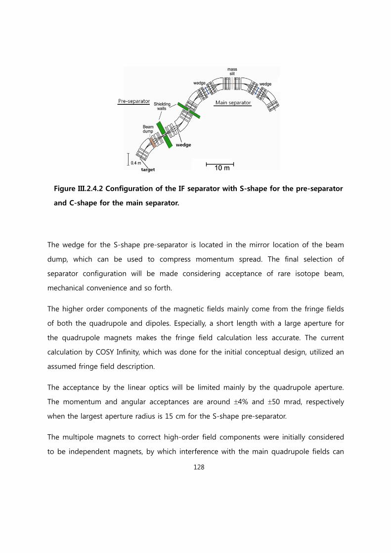
128
Figure III.2.4.2 Configuration of the IF separator with S-shape for the pre-separator
and C-shape for the main separator.
The wedge for the S-shape pre-separator is located in the mirror location of the beam
dump, which can be used to compress momentum spread. The final selection of
separator configuration will be made considering acceptance of rare isotope beam,
mechanical convenience and so forth.
The higher order components of the magnetic fields mainly come from the fringe fields
of both the quadrupole and dipoles. Especially, a short length with a large aperture for
the quadrupole magnets makes the fringe field calculation less accurate. The current
calculation by COSY Infinity, which was done for the initial conceptual design, utilized an
assumed fringe field description.
The acceptance by the linear optics will be limited mainly by the quadrupole aperture.
The momentum and angular acceptances are around 4% and 50 mrad, respectively
when the largest aperture radius is 15 cm for the S-shape pre-separator.
The multipole magnets to correct high-order field components were initially considered
to be independent magnets, by which interference with the main quadrupole fields can
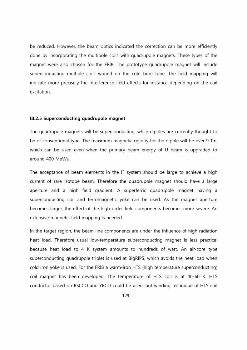
129
be reduced. However, the beam optics indicated the correction can be more efficiently
done by incorporating the multipole coils with quadrupole magnets. These types of the
magnet were also chosen for the FRIB. The prototype quadrupole magnet will include
superconducting multiple coils wound on the cold bore tube. The field mapping will
indicate more precisely the interference field effects for instance depending on the coil
excitation.
III.2.5 Superconducting quadrupole magnet
The quadrupole magnets will be superconducting, while dipoles are currently thought to
be of conventional type. The maximum magnetic rigidity for the dipole will be over 9 Tm,
which can be used even when the primary beam energy of U beam is upgraded to
around 400 MeV/u.
The acceptance of beam elements in the IF system should be large to achieve a high
current of rare isotope beam. Therefore the quadrupole magnet should have a large
aperture and a high field gradient. A superferric quadrupole magnet having a
superconducting coil and ferromagnetic yoke can be used. As the magnet aperture
becomes larger, the effect of the high-order field components becomes more severe. An
extensive magnetic field mapping is needed.
In the target region, the beam line components are under the influence of high radiation
heat load. Therefore usual low-temperature superconducting magnet is less practical
because heat load to 4 K system amounts to hundreds of watt. An air-core type
superconducting quadrupole triplet is used at BigRIPS, which avoids the heat load when
cold iron yoke is used. For the FRIB a warm-iron HTS (high temperature superconducting)
coil magnet has been developed. The temperature of HTS coil is at 40-60 K. HTS
conductor based on BSCCO and YBCO could be used, but winding technique of HTS coil
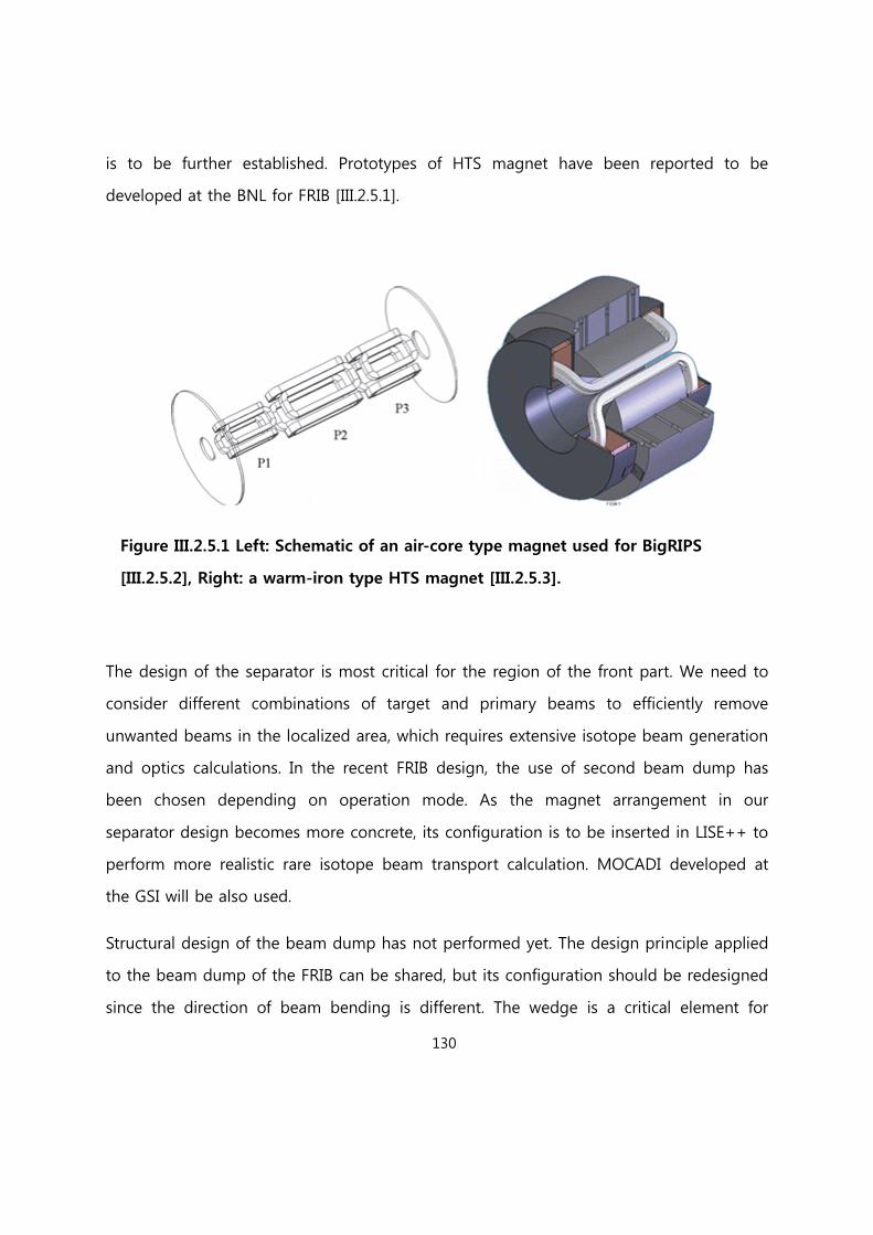
130
is to be further established. Prototypes of HTS magnet have been reported to be
developed at the BNL for FRIB [III.2.5.1].
Figure III.2.5.1 Left: Schematic of an air-core type magnet used for BigRIPS
[III.2.5.2], Right: a warm-iron type HTS magnet [III.2.5.3].
The design of the separator is most critical for the region of the front part. We need to
consider different combinations of target and primary beams to efficiently remove
unwanted beams in the localized area, which requires extensive isotope beam generation
and optics calculations. In the recent FRIB design, the use of second beam dump has
been chosen depending on operation mode. As the magnet arrangement in our
separator design becomes more concrete, its configuration is to be inserted in LISE++ to
perform more realistic rare isotope beam transport calculation. MOCADI developed at
the GSI will be also used.
Structural design of the beam dump has not performed yet. The design principle applied
to the beam dump of the FRIB can be shared, but its configuration should be redesigned
since the direction of beam bending is different. The wedge is a critical element for
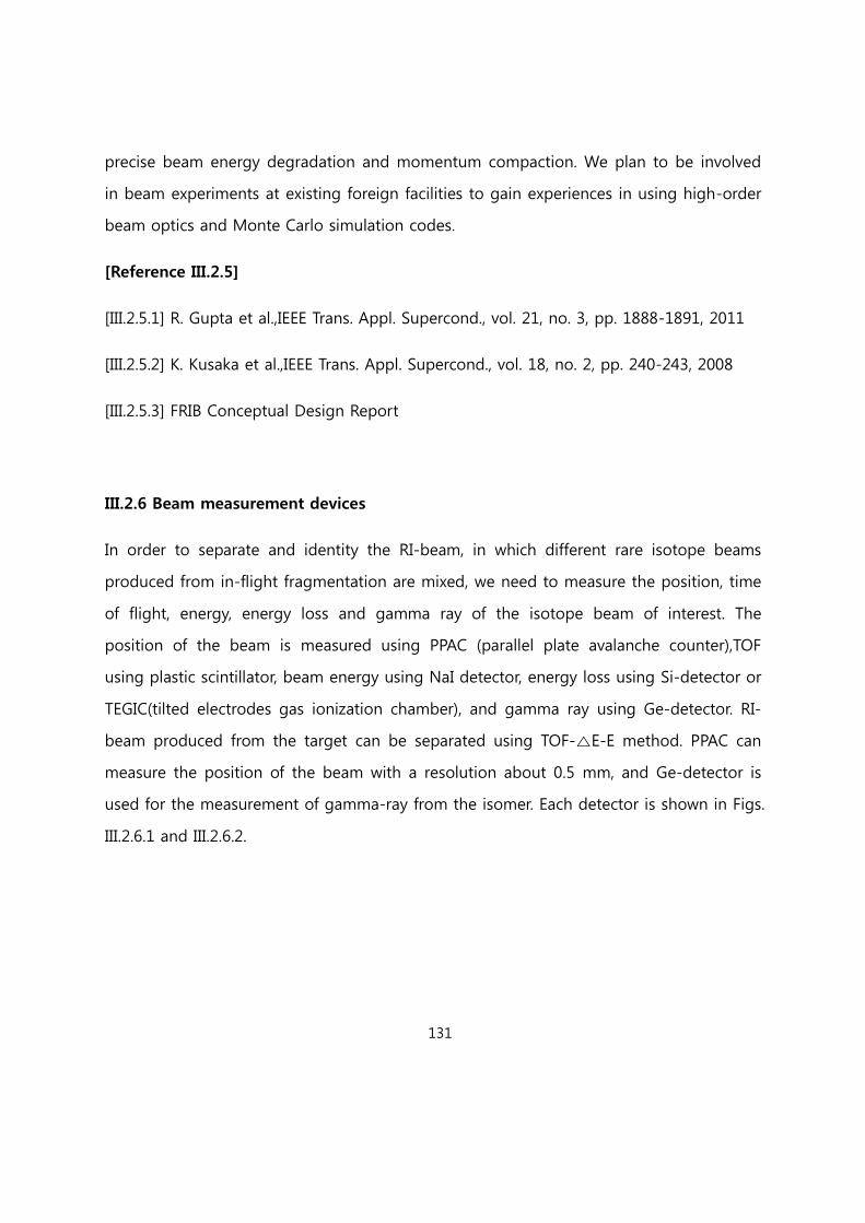
131
precise beam energy degradation and momentum compaction. We plan to be involved
in beam experiments at existing foreign facilities to gain experiences in using high-order
beam optics and Monte Carlo simulation codes.
[Reference III.2.5]
[III.2.5.1] R. Gupta et al.,IEEE Trans. Appl. Supercond., vol. 21, no. 3, pp. 1888-1891, 2011
[III.2.5.2] K. Kusaka et al.,IEEE Trans. Appl. Supercond., vol. 18, no. 2, pp. 240-243, 2008
[III.2.5.3] FRIB Conceptual Design Report
III.2.6 Beam measurement devices
In order to separate and identity the RI-beam, in which different rare isotope beams
produced from in-flight fragmentation are mixed, we need to measure the position, time
of flight, energy, energy loss and gamma ray of the isotope beam of interest. The
position of the beam is measured using PPAC (parallel plate avalanche counter),TOF
using plastic scintillator, beam energy using NaI detector, energy loss using Si-detector or
TEGIC(tilted electrodes gas ionization chamber), and gamma ray using Ge-detector. RI-
beam produced from the target can be separated using TOF-△E-E method. PPAC can
measure the position of the beam with a resolution about 0.5 mm, and Ge-detector is
used for the measurement of gamma-ray from the isomer. Each detector is shown in Figs.
III.2.6.1 and III.2.6.2.
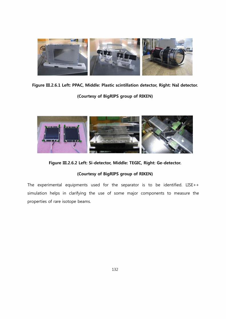
132
Figure III.2.6.1 Left: PPAC, Middle: Plastic scintillation detector, Right: NaI detector.
(Courtesy of BigRIPS group of RIKEN)
Figure III.2.6.2 Left: Si-detector, Middle: TEGIC, Right: Ge-detector.
(Courtesy of BigRIPS group of RIKEN)
The experimental equipments used for the separator is to be identified. LISE++
simulation helps in clarifying the use of some major components to measure the
properties of rare isotope beams.
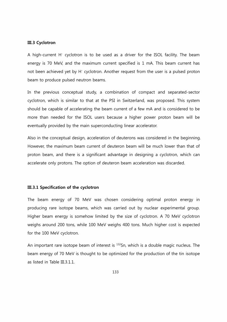
133
III.3 Cyclotron
A high-current H- cyclotron is to be used as a driver for the ISOL facility. The beam
energy is 70 MeV, and the maximum current specified is 1 mA. This beam current has
not been achieved yet by H- cyclotron. Another request from the user is a pulsed proton
beam to produce pulsed neutron beams.
In the previous conceptual study, a combination of compact and separated-sector
cyclotron, which is similar to that at the PSI in Switzerland, was proposed. This system
should be capable of accelerating the beam current of a few mA and is considered to be
more than needed for the ISOL users because a higher power proton beam will be
eventually provided by the main superconducting linear accelerator.
Also in the conceptual design, acceleration of deuterons was considered in the beginning.
However, the maximum beam current of deuteron beam will be much lower than that of
proton beam, and there is a significant advantage in designing a cyclotron, which can
accelerate only protons. The option of deuteron beam acceleration was discarded.
III.3.1 Specification of the cyclotron
The beam energy of 70 MeV was chosen considering optimal proton energy in
producing rare isotope beams, which was carried out by nuclear experimental group.
Higher beam energy is somehow limited by the size of cyclotron. A 70 MeV cyclotron
weighs around 200 tons, while 100 MeV weighs 400 tons. Much higher cost is expected
for the 100 MeV cyclotron.
An important rare isotope beam of interest is 132Sn, which is a double magic nucleus. The
beam energy of 70 MeV is thought to be optimized for the production of the tin isotope
as listed in Table III.3.1.1.

134
TableIII.3.1.1 Fission rate of 132Sn isotope for 70 kW ISOL system using UC2 target
p+238U fission rate Cut-off energy
70 MeV, 1.0mA, 30disk 1.22 x 10¹⁴ /s 20 MeV
The design and construction of a high-current cyclotron is challenging and takes a long
time to develop. A current plan of acquiring the cyclotron is to request commercial
vendors to deliver the fully operational cyclotron to the site. If needed, the installation
and maintenance can be handled by the RISP staffs upon contractual agreement with
cyclotron vendor for necessary technology transfer. A couple of vendors expressed
interests in working with us. One of the companies is in fact building a cyclotron for the
INFN in Italy with a similar specification for the beam.
Another possibility under consideration is to find a domestic vendor, which has previous
experiences in manufacturing cyclotrons preferably related to the 30 MeV cyclotron
presently in test operation at Jeong-Up city, Korea (Fig. III.3.1.1). The beam current
specified is 300 A, but is currently below 100 A when the beam is extracted by a
carbon foil. It is expected that the domestic company should possess the manpower
capable of designing all aspects of the cyclotron including cyclotron magnet and rf
system when it decide to join the bidding with foreign companies having more
experiences. Nonetheless, it would be reasonable to consider the involvement of RISP
staff to a certain degree.
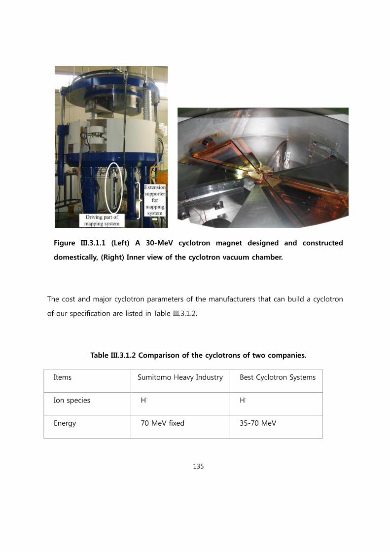
135
Figure III.3.1.1 (Left) A 30-MeV cyclotron magnet designed and constructed
domestically, (Right) Inner view of the cyclotron vacuum chamber.
The cost and major cyclotron parameters of the manufacturers that can build a cyclotron
of our specification are listed in Table III.3.1.2.
Table III.3.1.2 Comparison of the cyclotrons of two companies.
Items Sumitomo Heavy Industry Best Cyclotron Systems
Ion species H- H-
Energy 70 MeV fixed 35-70 MeV
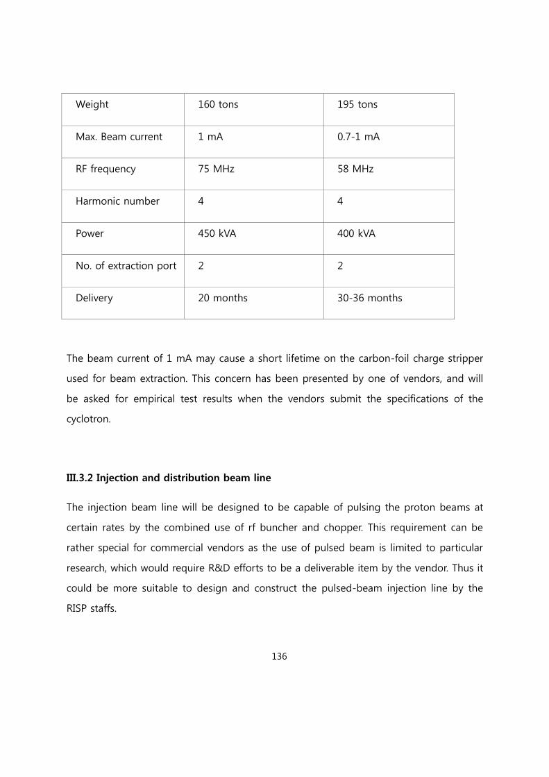
136
Weight 160 tons 195 tons
Max. Beam current 1 mA 0.7-1 mA
RF frequency 75 MHz 58 MHz
Harmonic number 4 4
Power 450 kVA 400 kVA
No. of extraction port 2 2
Delivery 20 months 30-36 months
The beam current of 1 mA may cause a short lifetime on the carbon-foil charge stripper
used for beam extraction. This concern has been presented by one of vendors, and will
be asked for empirical test results when the vendors submit the specifications of the
cyclotron.
III.3.2 Injection and distribution beam line
The injection beam line will be designed to be capable of pulsing the proton beams at
certain rates by the combined use of rf buncher and chopper. This requirement can be
rather special for commercial vendors as the use of pulsed beam is limited to particular
research, which would require R&D efforts to be a deliverable item by the vendor. Thus it
could be more suitable to design and construct the pulsed-beam injection line by the
RISP staffs.

137
The cyclotron facility will be mainly used for isotope beam production by the ISOL
method. Two target stations are minimally needed considering the alternative use of the
target system. Also, there will be a couple of rooms used for beam irradiation study. In
addition, a room can be allocated for isotope production for research, and then liquid
and gas targets will be needed.
To estimate radiation dose depending on the shielding thickness, MCNPX was used. Dose
accumulated for assumed 1 mAhr was calculated, and the yearly dose rate was used to
determine the shielding wall thickness. In addition, dose per hour is to be evaluated to
classify radiation areas when the beam is on a target. Some results of MCNPX calculation
were compared to the estimation by analytical expression.

138
III.4 ISOL system
The Isotope Separation On-Line (ISOL) technique has been used for over 50 years to
produce, ionize, mass separate, and study short-lived nuclear isotopes [III.4-1]. The
technique refers to a process in which radioactive atoms are produced in a thick target
and subsequently extracted from an ion source to form an ion beam. The radioactive
atoms are produced via nuclear reactions between an energetic ion beam and the target
nuclei. The RIs are extracted from the production target using specific techniques, ionized,
pre-accelerated and selected by means of high resolution electromagnetic devices, and
then re-accelerated. ISOL-type facilities provide high quality, low energy RI beams.
Figure III.4-1 shows the conceptual design layout of the ISOL system. The basic elements
of the ISOL facilities are the driver accelerator, the production target coupled to the ion
source, the RF beam cooler, the High Resolution Mass Separator (HRMS), the charge
breeder, the beam transport system, and the post-accelerator. According to the
experimental requirements, a HRMS is considered as a part of the transport system. Two
production target stations are proposed to produce various short-lived rare isotopes; one
is for spallation, in which mainly proton-rich isotopes are produced, and the other is a
fission target station. Note that a MW target station is planned in a future extension
beam line for the production of more intense RIBs. The primary accelerators are a high
energy proton (~600 MeV, 660 μA) LINAC and a cyclotron proton driver. In the
conceptual design, we concentrate on the feasibility study of the 70 kW direct fission
target to provide intense, high-quality beams of neutron-rich radioactive nuclei with
masses in the range of 80-160 created through uranium fission at a rate of 1014 fissions/s.
The idea of the high power direct target is an expansion of the facilities at HRIBF-ORNL
[III.4.2] and SPES-LNL [III.4.3]. The proposed production mechanism is fission induced by
protons in fissile material targets. The fission mechanism has the advantage that neutron-
rich radioactive beams can be produced. The rare isotopes produced in the production
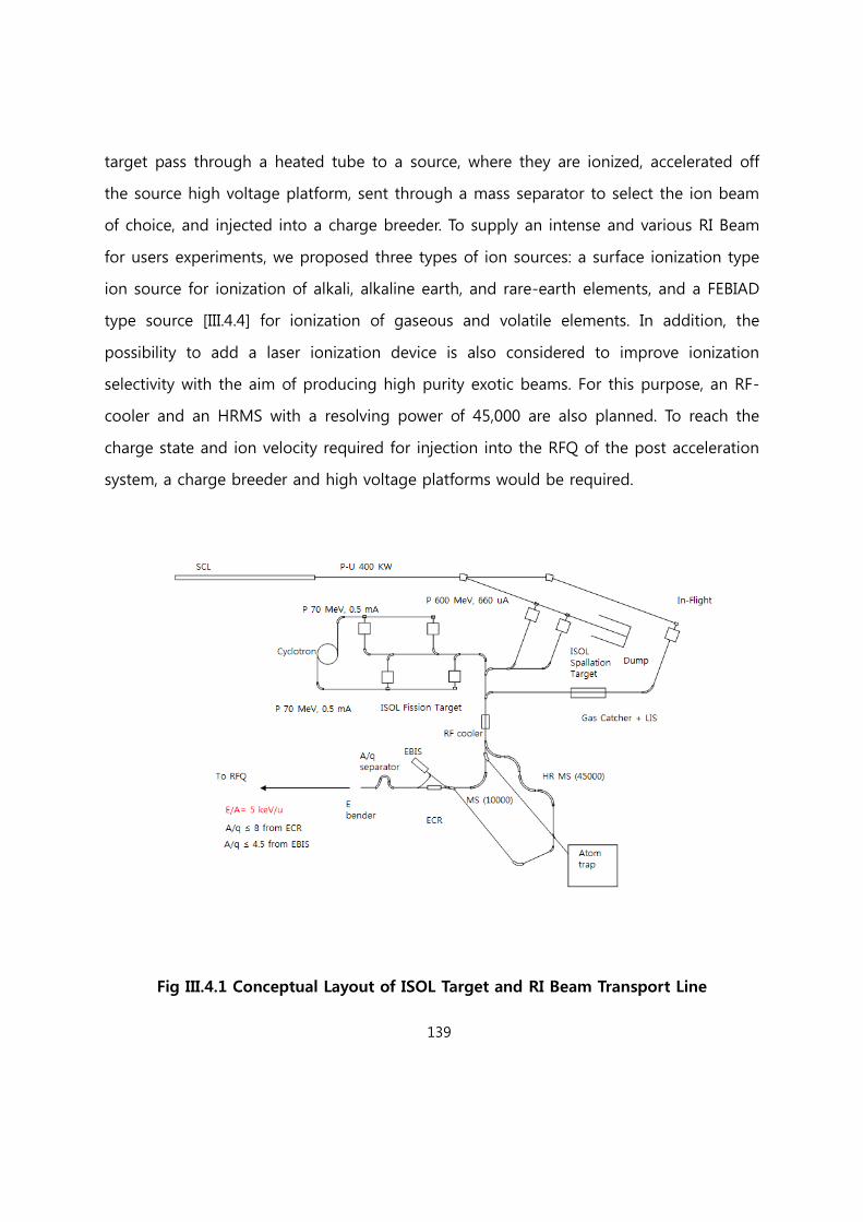
139
target pass through a heated tube to a source, where they are ionized, accelerated off
the source high voltage platform, sent through a mass separator to select the ion beam
of choice, and injected into a charge breeder. To supply an intense and various RI Beam
for users experiments, we proposed three types of ion sources: a surface ionization type
ion source for ionization of alkali, alkaline earth, and rare-earth elements, and a FEBIAD
type source [III.4.4] for ionization of gaseous and volatile elements. In addition, the
possibility to add a laser ionization device is also considered to improve ionization
selectivity with the aim of producing high purity exotic beams. For this purpose, an RF-
cooler and an HRMS with a resolving power of 45,000 are also planned. To reach the
charge state and ion velocity required for injection into the RFQ of the post acceleration
system, a charge breeder and high voltage platforms would be required.
Fig III.4.1 Conceptual Layout of ISOL Target and RI Beam Transport Line
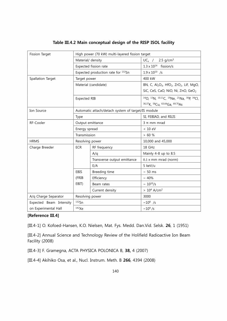
140
Table III.4.2 Main conceptual design of the RISP ISOL facility
Fission Target High power (70 kW) multi-layered fission target
Material/ density UCx / 2.5 g/cm3
Expected fission rate 1.3ⅹ1014 fission/s
Expected production rate for 132Sn 1.9ⅹ1010 /s
Spallation Target Target power 400 kW
Material (candidate) BN, C, Al2O3, HfO2, ZrO2, LiF, MgO,
SiC, CeS, CaO, NiO, Ni, ZnO, GeO2
Expected RIB 14O, 13N, 10,11C, 19Ne, 21Na, 30P, 34Cl,
36,37K, 58Cu, 63,64Ga, 69,70As
Ion Source Automatic attach/detach system of target/IS module
Type SI, FEBIAD, and RILIS
RF-Cooler Output emittance 3 π mm mrad
Energy spread < 10 eV
Transmission > 60 %
HRMS Resolving power 10,000 and 45,000
Charge Breeder ECR RF frequency 18 GHz
A/q Mainly 4-8 up to 8.5
Transverse output emittance 0.1 mm mrad (norm)
E/A 5 keV/u
EBIS
(FRIB
EBIT)
Breeding time ~ 50 ms
Efficiency ~ 40%
Beam rates ~ 1010/s
Current density > 104 A/cm2
A/q Charge Separator Resolving power 3000
Expected Beam Intensity
on Experimental Hall
132Sn ~108 /s
142Xe ~109 /s
[Reference III.4]
[III.4-1] O. Kofoed-Hansen, K.O. Nielsen, Mat. Fys. Medd. Dan.Vid. Selsk. 26, 1 (1951)
[III.4-2] Annual Science and Technology Review of the Holifield Radioactive Ion Beam
Facility (2008)
[III.4-3] F. Gramegna, ACTA PHYSICA POLONICA B, 38, 4 (2007)
[III.4-4] Akihiko Osa, et al., Nucl. Instrum. Meth. B 266, 4394 (2008)

141
III.4.1 ISOL Target and Ion Source
III.4.1.1 Concept of ISOL Target
Utilizing an ISOL system with fission targets has been the most effective way to produce
the medium mass neutron-rich RIBs [III.4.1.1.1]. The basic principle of the ISOL method is
the use of a light ion beam on a thick target of a high mass material to induce nuclear
reactions. Depending on the energy of the primary beam will undergo fission, spallation
or fragmentation. The reaction products diffuse out of the target material and are
transported via a transfer line into an ion source.
Several institutes are making an effort to produce high intense fission fragments using a
uranium target, under uranium carbide (UCx) form. In this report, the proposed target
configuration for proton beam energy of 70 MeV and intensity of 1 mA was split into
several thin disks in order to increase the total exchange surface for emitting thermal
radiation.
The combination of ISOL targets with ion sources is a key element for facilities aiming to
produce neutron-rich radioactive ion beams. The highest production of neutron-rich
isotopes can be achieved via proton- or neutron-induced fission of 238U and 232Th, while
proton-rich nuclei are efficiently produced through the spallation process on suitable
targets [III.4.1.1-2].
The concept of target configuration has been designed in order to satisfy some main
requirements, such as:
high production of Rare Isotope
short release times and highly efficient release
low power deposition for the materials .

142
The target is maintained at a high temperature (up to 2100 oC), and the RIs diffuse out
of the target and are transported to an ion source where the RI beams are formed. A
target configuration is chosen, consisting of a proton beam directly impinging on the
fission target. The main problem for this configuration concerns the power deposition of
the incident beam, due mainly to the electromagnetic interactions. To overcome this
problem, only protons with higher 238U fission cross-sections are exploited. The low
energy protons are less efficient production targets because they have lower fission
cross-sections and higher stopping power values, as shown in Fig. III.4.1.1.1.
Fig III.4.1.1.1 (left) Stopping power and fission cross-section for protons on UC2.
(right) Proton induced 238U fission cross section and the 132Sn production cross
section on the proton induced 238U fission
Forcing protons with energies lower than about 20 MeV toward a passive dump, the
power deposited in the target is lowered considerably, and a large number of fission
reactions are maintained. In order to optimize the heat dissipation and release time of
the fission products [III.4.1.1.3], a target constituted of porous thin uranium carbide disks
is used [III.4.1.1.4]. In this way, the cooling of the target is greatly simplified; in fact, due
to the vacuum environment, the heat dissipation is fully entrusted to the thermal
radiation, and this mechanism is directly proportional to the body surface. The use of
several thin disks increases the total surface and improves cooling.

143
The requirement of fast release from the target material implies a high operating target
temperature. Therefore, the target material must be a high-temperature, low vapor
pressure metal or refractory compound in solid, liquid, or powder form. Moreover, the
target must exhibit low vapor pressures (below 10-4 mbar) at elevated operating
temperatures (300 ºC – 2500 ºC) in order to avoid sublimation or vaporization of the
target material at vapor pressures exceeding those required for efficient ionization. Ideally,
the radioactive atoms should possess physical and chemical properties almost opposite
those of the target; that is, they should be diffused easily from the target material (either
in elemental or compound form) and be readily desorbed and vaporized from the target
surface. The pressed powder targets using UCx grains of 3 μm or smaller size were
developed in the Chemical and Material Sciences Facility at ORNL [III.4.1.1-5]. This
method can decrease the diffusion times of fission fragments in grains compared with
those of UCx-coated Reticulated Vitreous Carbon (RVC) fiber targets. This requires that
the desired radioactive species are not refractory, and that they do not form refractory
compounds within the target material.
Fig III.4.1.1.4 Concept of direct target configuration
All of these considerations lead to the system configuration shown in Fig. III.4.1.1-4 and
the following detailed parameters:

144
Incident 70 MeV proton beam has a current of 1 mA. The beam profile spans uniformly
over a circular distribution with a diameter of 7 cm, matching the disk diameter.
UC2 target (ρ=2.5 g/cm3), 1-mm-thick 30 disks (289 g of total mass).
Beam dump and box containing the disks are made of graphite.
The power deposition distribution, the fission rates, and the fission fragment distribution
were calculated mainly through a Monte Carlo simulation based on transportation model
MCNPX [III.4.1.1.6]. The following results were obtained through several Monte Carlo
calculations performed for the target configuration described in the previous section. A
power of 0.64 kW was deposited in the window, 36.72 kW in the thirty UCx disks, and
34.39 kW into the dump and graphite box (due to proton scattering). Thus, the average
power deposition for the UC2 target disks was about 1.22 kW/disk. With 1 mA, the
power deposition per unit volume in the UC2 target disks was 33.3 W/cm3. Figure
III.4.1.1.5 shows the radial profile of the power deposition in the disks. As expected, the
radial profile was uniform in the window (following the entering uniform beam profile),
and it became less and less flattened in the last disks because of the proton scattering.
The fission target/ion source chamber is designed in such a way that it can be removed
for servicing or storage. Since the target can be used several times, it will be stored into
a container with thick lead walls while not in use. The handling system must be designed
to transport such a heavy container into the area where the target will be used, to open
the container, and to connect the source chamber to the injector. After the experiment,
the source chamber must be first removed from the injector, then stored in the container,
and finally sent out of the hot area for further handling and long term storage. One note
that the 70 kW high power target are planning to design under the assumption of Φ 7
cm uniform beam from cyclotron driver. However if the driver cyclotron have 2 beam
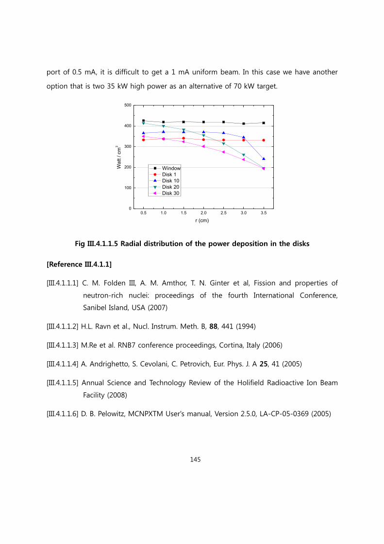
145
port of 0.5 mA, it is difficult to get a 1 mA uniform beam. In this case we have another
option that is two 35 kW high power as an alternative of 70 kW target.
Fig III.4.1.1.5 Radial distribution of the power deposition in the disks
[Reference III.4.1.1]
[III.4.1.1.1] C. M. Folden III, A. M. Amthor, T. N. Ginter et al, Fission and properties of
neutron-rich nuclei: proceedings of the fourth International Conference,
Sanibel Island, USA (2007)
[III.4.1.1.2] H.L. Ravn et al., Nucl. Instrum. Meth. B, 88, 441 (1994)
[III.4.1.1.3] M.Re et al. RNB7 conference proceedings, Cortina, Italy (2006)
[III.4.1.1.4] A. Andrighetto, S. Cevolani, C. Petrovich, Eur. Phys. J. A 25, 41 (2005)
[III.4.1.1.5] Annual Science and Technology Review of the Holifield Radioactive Ion Beam
Facility (2008)
[III.4.1.1.6] D. B. Pelowitz, MCNPXTM User's manual, Version 2.5.0, LA-CP-05-0369 (2005)
0.5 1.0 1.5 2.0 2.5 3.0 3.50
100
200
300
400
500
r (cm)
Wa
tt / c
m3
Window
Disk 1
Disk 10
Disk 20
Disk 30
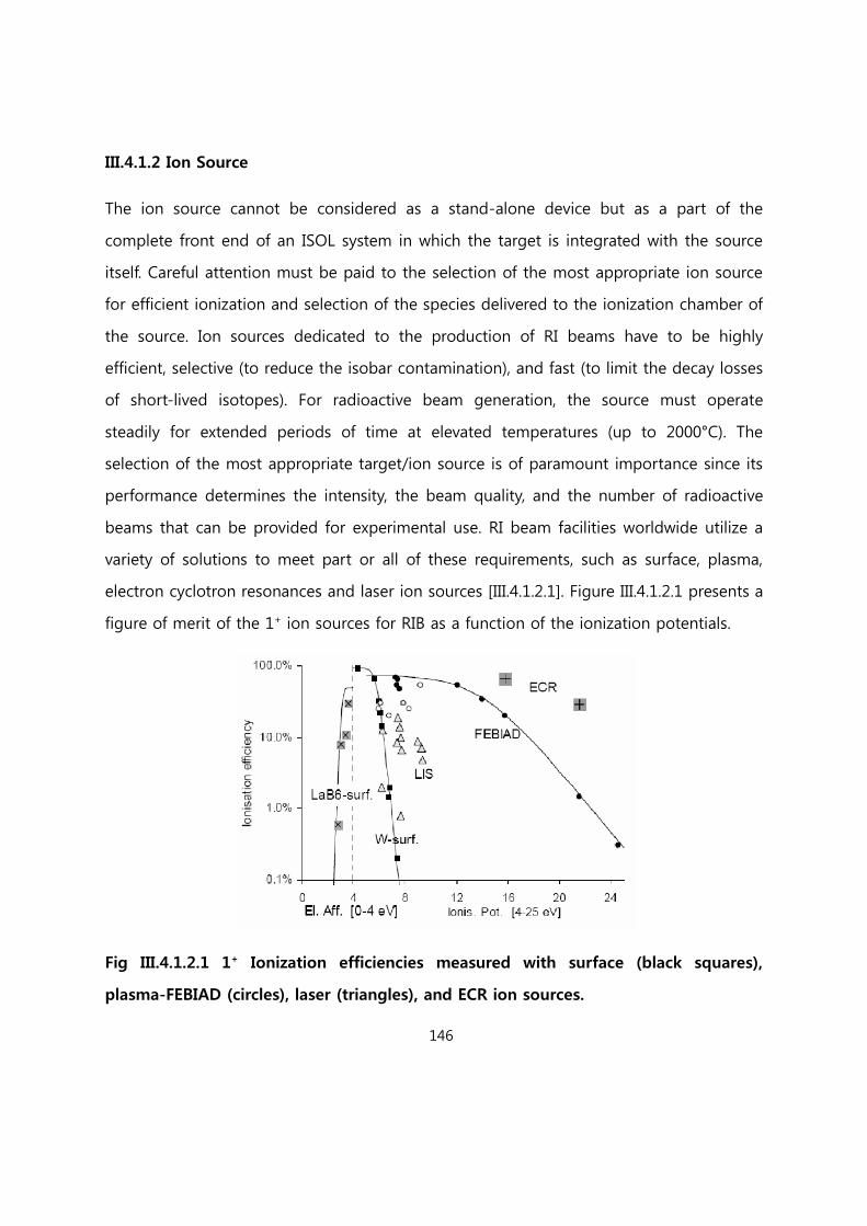
146
III.4.1.2 Ion Source
The ion source cannot be considered as a stand-alone device but as a part of the
complete front end of an ISOL system in which the target is integrated with the source
itself. Careful attention must be paid to the selection of the most appropriate ion source
for efficient ionization and selection of the species delivered to the ionization chamber of
the source. Ion sources dedicated to the production of RI beams have to be highly
efficient, selective (to reduce the isobar contamination), and fast (to limit the decay losses
of short-lived isotopes). For radioactive beam generation, the source must operate
steadily for extended periods of time at elevated temperatures (up to 2000°C). The
selection of the most appropriate target/ion source is of paramount importance since its
performance determines the intensity, the beam quality, and the number of radioactive
beams that can be provided for experimental use. RI beam facilities worldwide utilize a
variety of solutions to meet part or all of these requirements, such as surface, plasma,
electron cyclotron resonances and laser ion sources [III.4.1.2.1]. Figure III.4.1.2.1 presents a
figure of merit of the 1+ ion sources for RIB as a function of the ionization potentials.
Fig III.4.1.2.1 1+ Ionization efficiencies measured with surface (black squares),
plasma-FEBIAD (circles), laser (triangles), and ECR ion sources.

147
For RI beam generation, the source should ideally exhibit the following properties:
high ionization efficiency and chemical selectivity
high temperature operation and flexibility for adaptation to different temperature
ranges and modes of operation
low energy spreads
stable electrical and mechanical properties
The source should also be designed for safe and practical insertion/removal from the
ISOL facility in order to permit changing of the target material and source repairs. We
consider three kinds of ion sources for the direct target: the Surface Ion Source, the
Forced Electron Beam-Induced Arc Discharge (FEBIAD), and the Resonant Ionization Laser
Ion Source (RILIS). All three sources are used at ISOLDE and constitute a good reference
point for further RISP goals regarding ion source development.
[Reference III.4.1.2]
[III.4.1.2.1] J. Lettry, Proceedings of the 1999 Particle Accelerator Conference, New York
(1999).
III.4.1.3 Concept of Target Area
Because the facility will handle radioactive species, special care is devoted to radiation
protection safety, and several systems are added to prevent radiation hazards. Highly
radioactive areas like the target/IS bunker are ventilated using a nuclear ventilation
system. The control system will use a homogeneous architecture to integrate the many
subsystems necessary to operate the facility, ranging from the accelerator control to the
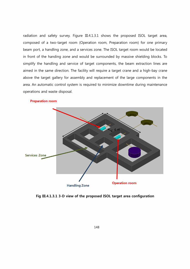
148
radiation and safety survey. Figure III.4.1.3.1 shows the proposed ISOL target area,
composed of a two-target room (Operation room, Preparation room) for one primary
beam port, a handling zone, and a services zone. The ISOL target room would be located
in front of the handing zone and would be surrounded by massive shielding blocks. To
simplify the handling and service of target components, the beam extraction lines are
aimed in the same direction. The facility will require a target crane and a high-bay crane
above the target gallery for assembly and replacement of the large components in the
area. An automatic control system is required to minimize downtime during maintenance
operations and waste disposal.
Fig III.4.1.3.1 3-D view of the proposed ISOL target area configuration

149
III.4.2 ISOL RI Beam Transport System
The ISOL beam transport system will manage the radioactive beam from the output of
the ionization source to the low-energy experimental area and to the post-accelerator
complex. At the ion source exit (located on a high voltage platform), the beam has
charge state 1+ and energy of 30-40 keV due to the extraction voltage. One of the main
problems of operating an ISOL facility is the beam purification, because the extracted
species are transported according to their A/q value. To improve the isotope selection,
three mass separators with different mass resolving powers will be implemented along
the transport line. The first separation stage is the pre-mass separator with a resolving
power of 100. The second and main purification stage is the High Resolution Mass
Separator (HRMS), which has a resolving power of about 10,000, 45,000. The last
separator will be installed after the charge breeder to avoid contamination of the
selected beam by the stable contaminants introduced by the charge breeder itself. Due
to the low rigidity of the beam, electrostatic quadrupoles can be used to focus and
transport the beam. This guarantees reliable beam handling and a simple procedure to
configure the beam transport line. The electrostatic devices scale with the voltage of the
source and are independent of the ion beam charge. Thus, the optic of the beam line
inside the production platform does not need further adjustment after configuration if
the source is operated at a fixed voltage. Also, the beam transport along the beam lines
outside of the platform can be achieved by an electrostatic lens. As in other facilities, we
plan to install an RF-cooler device as a beam cooler. The details and advantages of this
device are described later.
In recent year, A KEK on-line isotope facility of a TRIAC facility, was transferred to KAERI
in korea except for Target and ion source. This ISOL facility was used for production and
separation of rare isotope using UCx target and can accelerate the isotopes up to 1.1 A
MeV. The facility which is being installed will be used for the developments of ISOL

150
target/ion source and ISOL RI beam transport system, a performance test of detection
system, and so on.
RF-Cooler : To improve the performance of the high-resolution mass separator, an RF-
cooler will be installed to reduce the incoming beam emittance before separation. An RF-
cooler offers reduced transverse emittance, energy spread, and beam-bunching capability
for a wide range of masses on a time scale (< ms) appropriate for radioactive ion beams.
The RF-cooler depends on the emittance of the target/ion source used; the resulting
emittance is typically a factor of 10 or better. In this cooler, the beam emittance is
reduced, sending the beam with a low energy (E<100 eV) through a gas damping, which
removes the transversal component of the velocity. In other words, the beam
temperature is cooled by the interactions with a cold gas. This step is necessary to
reduce the beam speed and thus increase the time of interaction. This is accomplished
by placing the device on an insulated platform with a proper voltaged. This solution
allows for energy recovery after the cooling process. The deceleration and mainly the
reacceleration optics have to be well designed to preserve the beam emittance. An RF
quadrupole filter is used to prevent beam particle diffusion through the gas during the
interaction process. The quadrupole filters were developed for an ion trap and consist of
a set of four electrodes. Each pair of opposing electrodes is connected and driven by a
RF voltage with a polarity opposite that of the other electrode pair. According to the
existing device, the space necessary to allocate this RF-cooler is about 1-1.5 m. The
beam optics designed to transport the beam from the RF-cooler, through the HV
platform and to the HRMS have to be thoroughly studied to avoid deterioration of the
beam emittance.
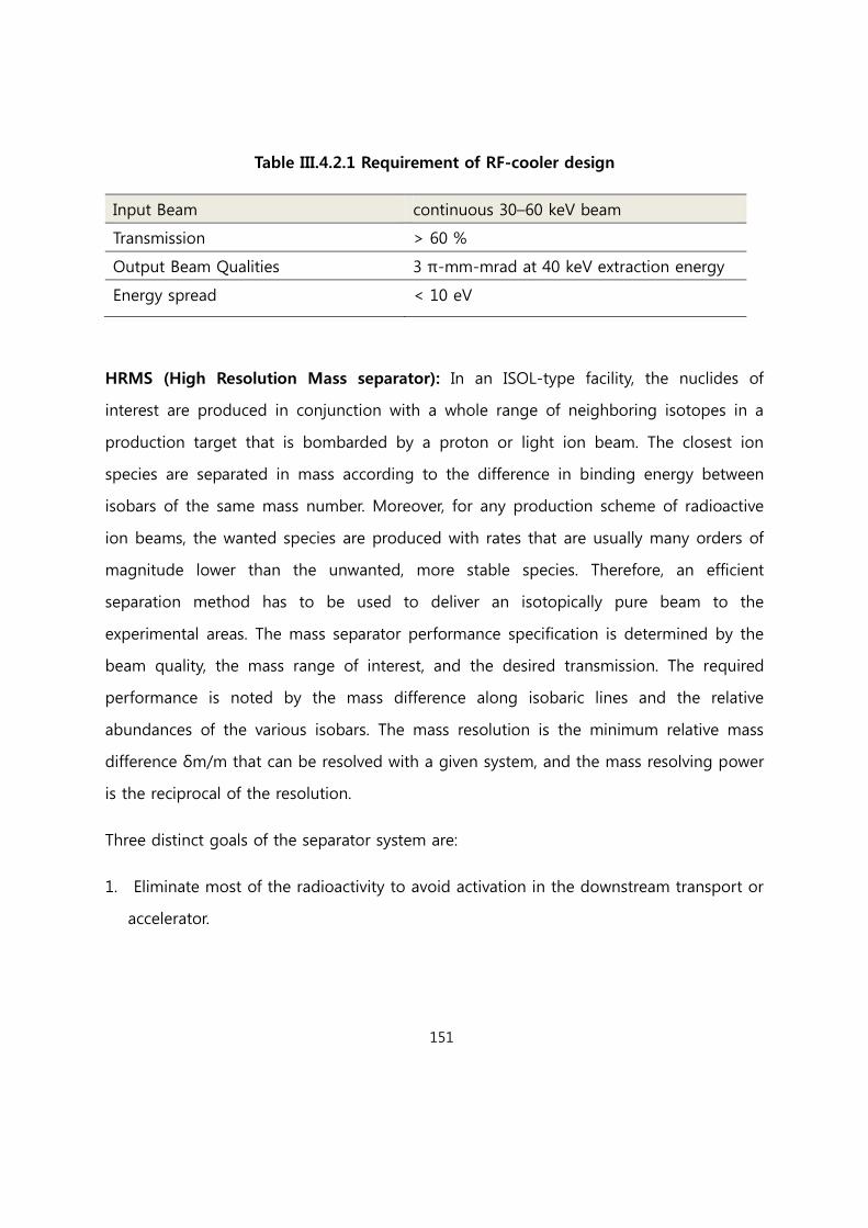
151
Table III.4.2.1 Requirement of RF-cooler design
Input Beam continuous 30–60 keV beam
Transmission > 60 %
Output Beam Qualities 3 π-mm-mrad at 40 keV extraction energy
Energy spread < 10 eV
HRMS (High Resolution Mass separator): In an ISOL-type facility, the nuclides of
interest are produced in conjunction with a whole range of neighboring isotopes in a
production target that is bombarded by a proton or light ion beam. The closest ion
species are separated in mass according to the difference in binding energy between
isobars of the same mass number. Moreover, for any production scheme of radioactive
ion beams, the wanted species are produced with rates that are usually many orders of
magnitude lower than the unwanted, more stable species. Therefore, an efficient
separation method has to be used to deliver an isotopically pure beam to the
experimental areas. The mass separator performance specification is determined by the
beam quality, the mass range of interest, and the desired transmission. The required
performance is noted by the mass difference along isobaric lines and the relative
abundances of the various isobars. The mass resolution is the minimum relative mass
difference δm/m that can be resolved with a given system, and the mass resolving power
is the reciprocal of the resolution.
Three distinct goals of the separator system are:
1. Eliminate most of the radioactivity to avoid activation in the downstream transport or
accelerator.
152
2. Eliminate the stable contaminants produced in the source system (stable isobars,
isotopes with the same mass-to-charge ratio, and molecules), which can outnumber
the desired radioactive ion beam by several orders of magnitude.
3. Separate all radioactive ion species.
The first goal is achieved by incorporating a low-resolution pre-separator magnet just
downstream of the target/source. A resolving power of only ~100 is sufficient to remove
most of the radioactivity at the image slit of the pre-separator. For light ions, the
elimination of most of the contaminants requires a resolving power in the range of
1,000–2,000, although in some particular cases, a resolving power of 20,000 may be
needed. The selectivity of the source system could help to suppress these specific
elements. Also, the use of experimental techniques to reject some unwanted components
may allow for some relaxation in the separation requirements, resulting in better
transmission and reduced tuning time. In general, the mass difference between isobars is
smaller for heavier ions, and a mass-resolving power of 10,000 or more would be
sufficient in many cases. The beam quality is important in determining the resolving
power of a certain magnetic system. The resolving power is given by the ratio of the
magnet dispersion to the beam width at the focal point (Rm = Dm/x). Thus, beam
emittance is an important criterion that affects the achievable spot size for a given tune.
For example, the use of an RF-cooler to significantly reduce the emittance of the beam
entering a mass-separator system can significantly improve the resolving power.
The proposed configuration is shown in Fig. III.4.2.1. Each of two-target source units has
a pre-separator with a resolving power of 100. After separation, the beams are directed
to the HRMS, which would have a resolution of 45,000 and be equipped with an RF-
cooler to reduce the emittance of the beam before separation. Presently, there are a few
isobaric separators planned or already constructed in some European and U.S.
laboratories. However high technologies are required for development of the 45,000 and

153
long times are needed. For reduce the risk of 45,000 HRMS we are planning to develop
10,000 HRMS which have a capability of isotope selectivity with a laser ion source.
Figure III.4.2.1 shows the conceptual design of 45,000 HRMS (High Resolution Mass
Separator) and it consist of 4 dipole magnets and 12 quadrupole magnets and total
length is about 38 m. The dipole magnet has deflection angle of 90 degree and central
trajectory radius of 2 m. The quadrupole magnet has effective length of 20.0 cm and half
aperture of 4.0 cm.
Fig III.4.2.1 Schematic view of HRMS
The HRMS have four focus points from F1 to F4. Figure III.4.2.2 shows the result of
beam envelope. Upper and lower panel indicate beam envelope in horizontal and vertical,
respectively. The absolute value of dispersion at each focus points are 5.6, 19.2, 22.8, 29.4
cm/%. Figure III.4.2-3 shows the result of separation for momentum difference of
1/80000 at each focus points. As show in Figure 3, the tail in low momentum side
increase with increase in dispersion. In order to collect the tail, the higher component of
magnet is under consideration.
The mass resolving power from present calculation is about 55000 at F4. For all
calculation and simulation using TRANSPORT and TURTLE program, the initial beam
emittance is 3 π mm mrad.

154
The present results indicate possibility of high resolution mass separator with RM >
45000. However, the results by COSY infinity or GICOSY disagree with the present results.
The reason for the discrepancy is not yet understood. It will take firm steps to clarify the
cause. The other hand, the present results indicate the requirement specification of RF-
cooler. The beam emittance after RF-cooler has got to be below 3 π mm mrad.
Fig III.4.2.2 Beam Envelope in horizontal and vertical direction using TRANSPORT
program
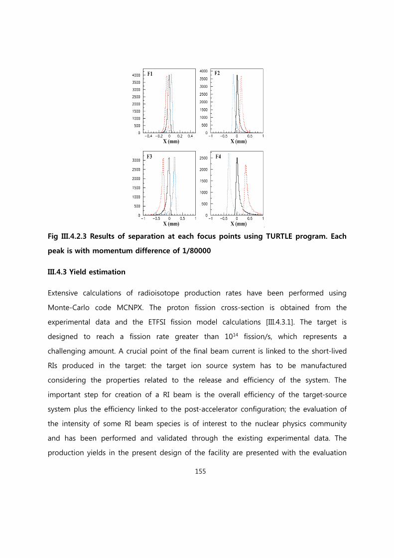
155
Fig III.4.2.3 Results of separation at each focus points using TURTLE program. Each
peak is with momentum difference of 1/80000
III.4.3 Yield estimation
Extensive calculations of radioisotope production rates have been performed using
Monte-Carlo code MCNPX. The proton fission cross-section is obtained from the
experimental data and the ETFSI fission model calculations [III.4.3.1]. The target is
designed to reach a fission rate greater than 1014 fission/s, which represents a
challenging amount. A crucial point of the final beam current is linked to the short-lived
RIs produced in the target: the target ion source system has to be manufactured
considering the properties related to the release and efficiency of the system. The
important step for creation of a RI beam is the overall efficiency of the target-source
system plus the efficiency linked to the post-accelerator configuration; the evaluation of
the intensity of some RI beam species is of interest to the nuclear physics community
and has been performed and validated through the existing experimental data. The
production yields in the present design of the facility are presented with the evaluation

156
of the final beam current on the target. The intensity I of an exotic beam available for an
experiment is determined by the following factors:
I = Φ· N·σ ·εr·εi·εc·εs·εcb·εt·εp
σ: the cross-section of the production reaction,
Φ: the primary beam intensity,
N: the thickness of the production target,
εr: the efficiencies of release of the target and transfer,
εi: the efficiency of the ion source,
εc: the efficiency of the RF-cooler,
εs: the efficiency of the separator,
εcb: the efficiency of the charge breeder,
εt: the delay transfer efficiency due to radioactive decay losses,
εp: the efficiency of the post-accelerator.
The final RI beam current depends on the efficiencies of several chemical physical
processes and beam transport elements. For ISOL facilities, the total efficiency is highly
case-dependent and lies between 10-2 and 10-6. To evaluate the final beam, the exotic
species must be followed along their paths. The exotic species are produced inside the
target as neutral atoms and are extracted in a gas phase due to the high operating
temperature of the target (2000oC). This process is governed by the release efficiency;
that is, those of the diffusion processes in the uranium carbide grains, the effusion in the
container, and the injection in the ion source. As soon as the atoms are in the ion source,
they should be ionized 1+ to be extracted and injected into the transport system. This

157
process is controlled by the source ionization efficiency. For an efficient reacceleration, it
is necessary to increase the charge states of the ions.
This increase is achieved by the charge breeder. Finally, we must consider the overall
efficiency of the transport and post-accelerator system. All of these parameters strongly
affect the final current, but the target efficiency itself is complicated. The diffusion in the
material is a complicated and unknown phenomenon, especially when the material is at
high temperature; it strictly depends on the material structure and the temperature at
which the material is maintained [III.4.3.2]. The calculated fission rate in all 30 disks
approached 1.3 × 10¹⁴ fissions/s. The isotope in-target production reached values up to
~ 1012 atoms/s (see Figure III.4.3-1). The 132Sn isotope is a double-magic nucleus and is
thus one of the radioactive nuclei of interest. Its production was here estimated to be ~
1010 pps on. A more general view of the in-target yields is given in Figure III.4.3-2. The
overall efficiency is defined as the product of the efficiency of release from the target,
the decay losses, and the efficiency of transport to and ionization in the ion source. This
overall efficiency depends critically on the detailed design of the production target, the
chemistries of the extracted activities, and the ion source design. The efficiencies of these
three processes are more important in determining the resulting secondary beam
intensities than they are for determination of the primary intensity and the formation
cross-section, which determine only the production rate of the target. The expected
beam intensities in a uranium target are evaluated and shown in Table III.4.3.1, taking
into account the efficiencies experimentally obtained from other studies [III.4.3.3, III.4.3.4].
Estimates of RI beam intensities also have to consider the transmission associated with
the RF-cooler, the mass separation, charge breeding, and the secondary beam
acceleration. In cases of high selectivity in the ion source, as for alkalis and noble gases,
isobar separation is not required, so the mass separation can be performed with low
resolution and high transmission. For cases with minor selectivity in the ion source, the
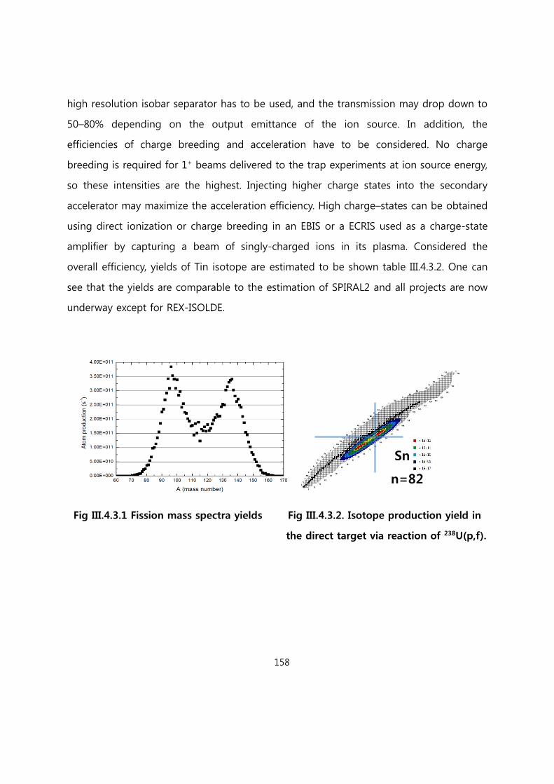
158
high resolution isobar separator has to be used, and the transmission may drop down to
50–80% depending on the output emittance of the ion source. In addition, the
efficiencies of charge breeding and acceleration have to be considered. No charge
breeding is required for 1+ beams delivered to the trap experiments at ion source energy,
so these intensities are the highest. Injecting higher charge states into the secondary
accelerator may maximize the acceleration efficiency. High charge–states can be obtained
using direct ionization or charge breeding in an EBIS or a ECRIS used as a charge-state
amplifier by capturing a beam of singly-charged ions in its plasma. Considered the
overall efficiency, yields of Tin isotope are estimated to be shown table III.4.3.2. One can
see that the yields are comparable to the estimation of SPIRAL2 and all projects are now
underway except for REX-ISOLDE.
Fig III.4.3.1 Fission mass spectra yields Fig III.4.3.2. Isotope production yield in
the direct target via reaction of 238U(p,f).
n=82
Sn
n

159
Table III.4.3.1. Intensities calculated considering release, ionization, and acceleration
efficiencies for different isotopes
Isotope Half-life Yield of production target
(pps)
Overall eff. (%) Expected beam on the
experimental target (pps)
78Zn 1.5 s 2.19 x 10¹⁰ 0.04 1 x 10⁷
90Kr 32 s 1.99 x 10¹² 1.00 2 x 10¹⁰
94Kr 0.2 s 1.29 x 10¹¹ 0.51 7 x 10⁸
97Rb 170 ms 1.02 x 10¹¹ 0.88 9 x 10⁸
124Cd 1.24 s 4.98 x 10¹¹ 0.02 1 x 10⁸
132Sn 40 s 1.95 x 10¹⁰ 0.45 8 x 10⁷
133In 180 ms 3.75 x 10⁷ 0.18 7 x 10⁴
142Xe 1.22 s 2.84 x 10¹⁰ 2.08 6 x 10⁸
144Cs 1.01 s 6.01 x 10¹⁰ 0.12 7 x 10⁷
Table III.4.3.2 Expectation yield of Sn Isotope at low energy experimental hall
[Reference III.4.3]
[III.4.3.1] A. Mamdouh, J.M. Pearson, M. Rayet, E Tondeur, Nucl. Physics A, 644, 389 (1998)
[III.4.3.2] J. Crank, The Mathematics of Diffusion, Clarendon Press (1956).
[III.4.3.3] H.L. Ravn et al., Nucl. Instrum. Meth. B, 88, 441 (1994)
[III.4.3.4] B. Fogelberg et al., Nucl. Instrum. Meth. B, 70, 137 (1992)

160
III.5 ISOL Post Accelerator
III.5.1 Charge Breeder
Charge breeder, which transforms externally injected ions with a charge state 1+ to a
higher charge states n+, is necessary for multiplying the charge state of extracted rare
isotopes (RI) from the ISOL target-ion source units for the efficient acceleration at the
next stage. A charge breeder has to be capable of getting a high efficiency for the
charge state breeding process in a short time compared to the half-life of the interest
exotic nuclei. In addition, the higher intensities of RI beams up to 1012 ions/s with a low
level of background contaminants have to be handled by the charge breeder. In order to
cover the various experiments planned in RISP, output beam should be in the charge
state, +12 to +25 with Q/A > 1/9, and its emittance should be less 0.35 mm-mrad
(normalized, 90 %) from singly charged various species (A = 80 ~ 160) input beam.
The two types of breeders, electron beam ion source (EBIS) and electron cyclotron
resonance (ECR) ion source, have distinct characteristic features. The advantages that
make the EBIS attractive are a low level of background contaminants, fast charge
breeding time and low A/Q. Many facilities including EURISOL, FRIB at MSU and BNL
employed the EBIS system for their charge-breeding device. The weaknesses of the EBIS
are the limited RI beam acceptance, system complexity, short cathode lifetime, and traits
of pulsed mode operation. The limitation on RI beam acceptance can be overcome by
increasing the electron beam current and density while at the same time shortening the
required breeding times.
An EBIS can be used to produce high intensity of RI beams, and is an excellent choice for
injection into a re-accelerator for ISOL Linac because the length of ISOL Linac is shorter
than Drive Linac. An EBIS relies on a beam of electrons that collide with trapped ions,
resulting in the stepwise ionization and production of highly charged ions. As the rate of

161
these collisions can be increased by creating a high density of electrons, the beam is
compressed using a strong magnetic field. The total charge of ions extracted per pulse is
proportional to the number of electrons in the trap. The maximum intensity of ion beams
for ECR charge breeder will not exceed 107 per second. A charge breeder based on an
EBIS will be up to 109 ~ 1011 per second [1]. For the EBIS of BNL, it shows that intensity
of Au32+ and Fe20+ are several times of 109 per second [2].
An EBIS composes an electron gun which generates electron beam, drift tube, and super-
conducting solenoid, which traps electrons and ion beam, vacuum system and collector
system. Because the intensity of ions is directly current of electrons times trap length, the
EBIS is designed high current electron gun and long trap length. Avoiding background
current, the chamber of EBIS is operation at Ultra High Vacuum (UHV). In order to offer
UHV and long life time, a cathode of electron gun must to use dispenser cathode. High
current and a very small diameter of electron beam leads to a low emittance of the
extracted RI beam. The electron gun is required to have high compression ratio and this
can be achieved by using super-conducting solenoid. The injected RI beams are radially
trapped by space charge of an intense electron beam and then ionized by these
electrons impact.
Ion accumulation process in EBIS is single and double ionization and charge exchange
processes, radiative recombination, charge exchange between ions and neutral atoms,
electron capture by a higher charged ion from a lower charged one, ion heating by
electrons and ion escape from the trap. In order to increase breeding efficiency, A
dedicated EBIS for charge breeding process has to be studied [3], [4].
A charge state breeder with the EBIS system was already carried out at several other
facilities. The design parameters of the EBIS proceeded at other facilities are listed in
Table III.5.1.1.
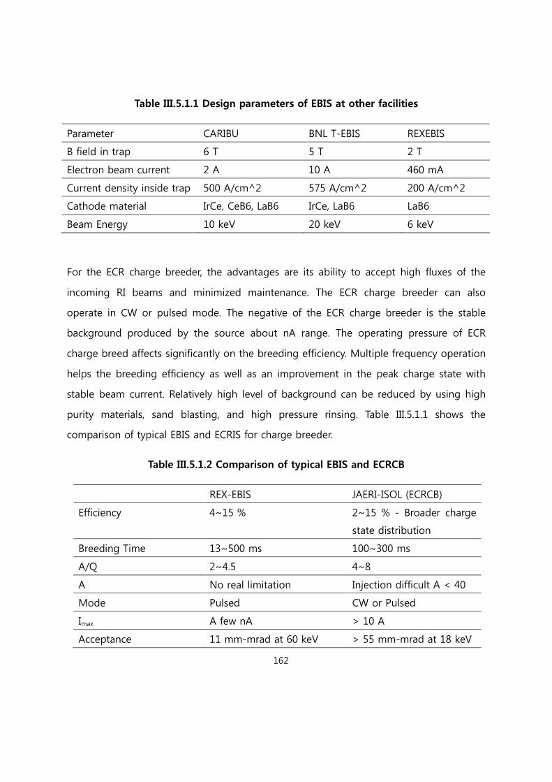
162
Table III.5.1.1 Design parameters of EBIS at other facilities
Parameter CARIBU BNL T-EBIS REXEBIS
B field in trap 6 T 5 T 2 T
Electron beam current 2 A 10 A 460 mA
Current density inside trap 500 A/cm^2 575 A/cm^2 200 A/cm^2
Cathode material IrCe, CeB6, LaB6 IrCe, LaB6 LaB6
Beam Energy 10 keV 20 keV 6 keV
For the ECR charge breeder, the advantages are its ability to accept high fluxes of the
incoming RI beams and minimized maintenance. The ECR charge breeder can also
operate in CW or pulsed mode. The negative of the ECR charge breeder is the stable
background produced by the source about nA range. The operating pressure of ECR
charge breed affects significantly on the breeding efficiency. Multiple frequency operation
helps the breeding efficiency as well as an improvement in the peak charge state with
stable beam current. Relatively high level of background can be reduced by using high
purity materials, sand blasting, and high pressure rinsing. Table III.5.1.1 shows the
comparison of typical EBIS and ECRIS for charge breeder.
Table III.5.1.2 Comparison of typical EBIS and ECRCB
REX-EBIS JAERI-ISOL (ECRCB)
Efficiency 4~15 % 2~15 % - Broader charge
state distribution
Breeding Time 13~500 ms 100~300 ms
A/Q 2~4.5 4~8
A No real limitation Injection difficult A < 40
Mode Pulsed CW or Pulsed
Imax A few nA > 10 A
Acceptance 11 mm-mrad at 60 keV > 55 mm-mrad at 18 keV

163
Emittance 15-20 mm-mrad at 20 keV 10 mm-mrad at 20 keV
Background < 0.1 pA < 1 nA
Reliability Overall system complex Robust and simple
Frequency 2.45 + 12 GHz
Both systems have complementary characteristics to each other as shown before. The
ECR type is suited for producing high intensity RI beams while EBIS system is good for
short lifetime isotopes and high purity RI beams. Using an existing 1+ to n+ scheme
with both an ECR and an EBIS as a charge breeders will work up to what have been
achieved in other labs worldwide. However, efficiency is everything in the production of
RI beams. It would be nice to explore a 1+ to n+ scheme by finding a radiation-resistant
magnet to construct an ECR ion source that can be located very close to the production
target to product the n+ ions from the target neutrals with better efficiency. Again not all
these options are required at the beginning but careful planning of the production area
layout to account for future upgrade options is required. A ECR charge breeder based
on the KAERI 14 GHz ECR ion source and KBSI 28 GHz ECR ion source may also be a
good start to get the program started. The final decision on the charge breeder for RISP-
ISOL will be taken according to the final evaluation of the facility layout, taking into
account budget, performances and construction schedule.
[Reference III.5.1]
[III.5.1.1] P. Ostroumov et al., 2010 IOP Publishing Ltd and SISSA
[[III.5.1.2] J. Alessi et al., Proceedings of the 2003 Particle Accelerator Conference 89(2003)
[[III.5.1.3] S. Schwarz, G. Bollen et al., Nuclear Instruments and Methods in Physics
Research B 266 (2008) 4466
[[III.5.1-4] I V Kalagin et al., Plasma Sources Sci. Technol. 7 (1998) 441

164
III.5.2 LEBT, RFQ, MEBT
III.5.2.1 LEBT
The LEBT consists of solenoids and quadrupoles to provide transverse focusing for the
rare-isotope beams from the charge breeder. To get a small longitudinal emittance, a
buncher with 81.25 MHz is used at the entrance of RFQ. The location and the voltages
for the buncher is optimized to match the beam longitudinally with RFQ and to obtain
the high capture rate. The LEBT was optimized by the beams with the energy of 10 keV/u
and a q/A of 0.2. The beam has a normalized rms transverse emittance of 0.2 pi mm-
mrad and an energy spread of 0.2%. The beam is bunched and matched into a RFQ.
Transverse emittance growth in the LEBT is not observed.
III.5.2.2 RFQ
Due to higher q/A of the beams from the charge breeder, the RFQ can accelerate the
beam to higher energy of 300 keV/u compared to drive-accelerator and can result in
improvement of performance in beam dynamics of the re-accelerator linac. As the
beams are bunched at a buncher, RFQ can achieve higher acceleration efficiency. The
growth of the transverse emittance in RFQ is small. As the energy spread can an impact
on the longitudinal emittance from RFQ, it is important to achieve a small energy spread
from the charge breeder.
III.5.2.3 MEBT
Same MEBT layout as the drive-linac will be used.
III.5.3 ISOL Superconducting Linac

165
The ISOL post-accelerator is also a superconducting linac. As for the ISOL post-
accelerator lattice choice, we are planning to share the same doublet lattice as the driver
SC Linac to minimize types of accelerator components to reduce cost and R&D efforts.
Cavities of the same types and betas will be used as well as the same type of
cryomodules.
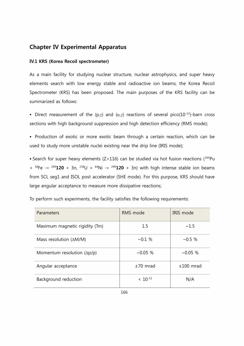
166
Chapter IV Experimental Apparatus
IV.1 KRS (Korea Recoil spectrometer)
As a main facility for studying nuclear structure, nuclear astrophysics, and super heavy
elements search with low energy stable and radioactive ion beams, the Korea Recoil
Spectrometer (KRS) has been proposed. The main purposes of the KRS facility can be
summarized as follows:
Direct measurement of the (p,) and (,) reactions of several pico(10-12)-barn cross
sections with high background suppression and high detection efficiency (RMS mode);
Production of exotic or more exotic beam through a certain reaction, which can be
used to study more unstable nuclei existing near the drip line (IRIS mode);
Search for super heavy elements (Z>116) can be studied via hot fusion reactions (244Pu
+ 58Fe → 299120 + 3n, 238U + 64Ni → 299120 + 3n) with high intense stable ion beams
from SCL seg1 and ISOL post accelerator (SHE mode). For this purpose, KRS should have
large angular acceptance to measure more dissipative reactions;
To perform such experiments, the facility satisfies the following requirements:
Parameters RMS mode IRIS mode
Maximum magnetic rigidity (Tm) 1.5 ~1.5
Mass resolution (M/M) ~0.1 % ~0.5 %
Momentum resolution (p/p) ~0.05 % ~0.05 %
Angular acceptance ±70 mrad ±100 mrad
Background reduction < 10-12 N/A
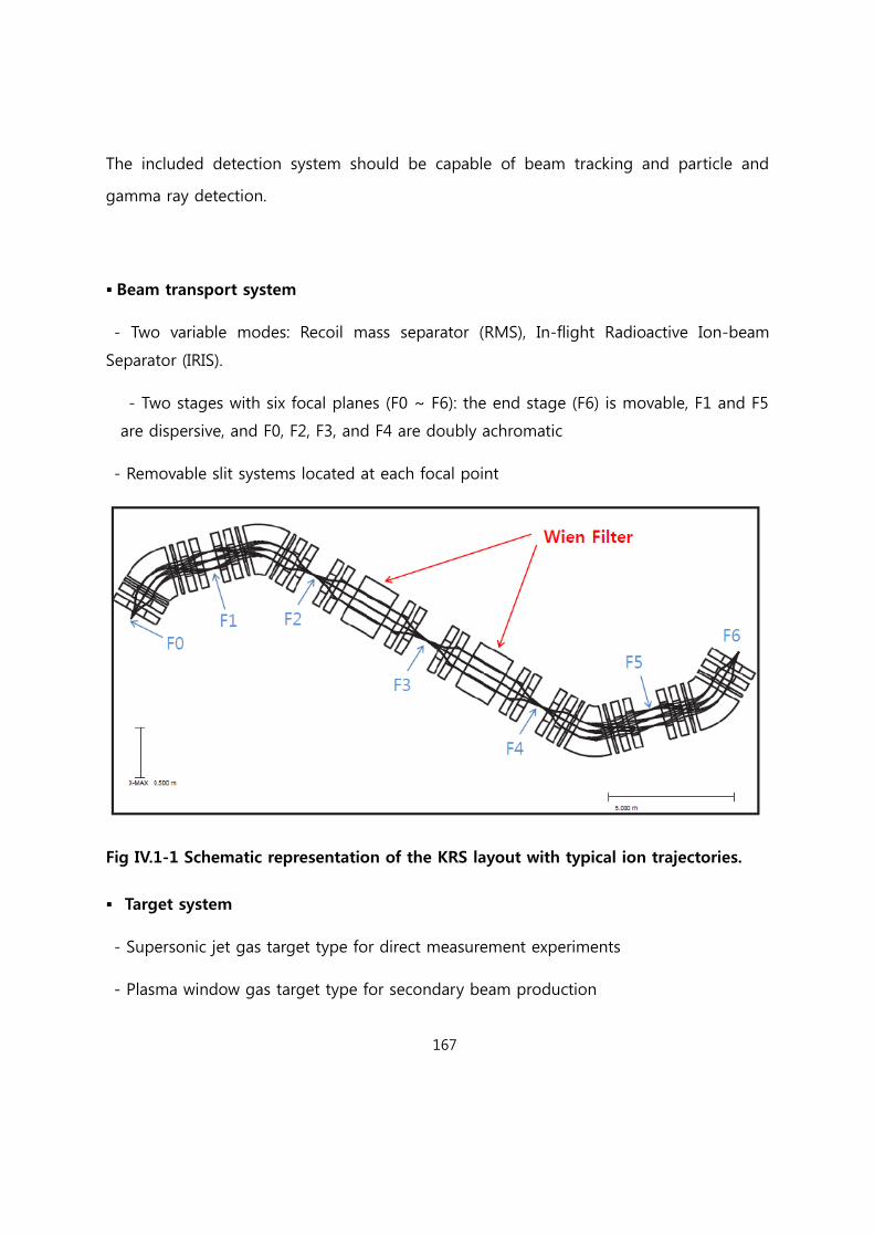
167
The included detection system should be capable of beam tracking and particle and
gamma ray detection.
Beam transport system
- Two variable modes: Recoil mass separator (RMS), In-flight Radioactive Ion-beam
Separator (IRIS).
- Two stages with six focal planes (F0 ~ F6): the end stage (F6) is movable, F1 and F5
are dispersive, and F0, F2, F3, and F4 are doubly achromatic
- Removable slit systems located at each focal point
Fig IV.1-1 Schematic representation of the KRS layout with typical ion trajectories.
Target system
- Supersonic jet gas target type for direct measurement experiments
- Plasma window gas target type for secondary beam production
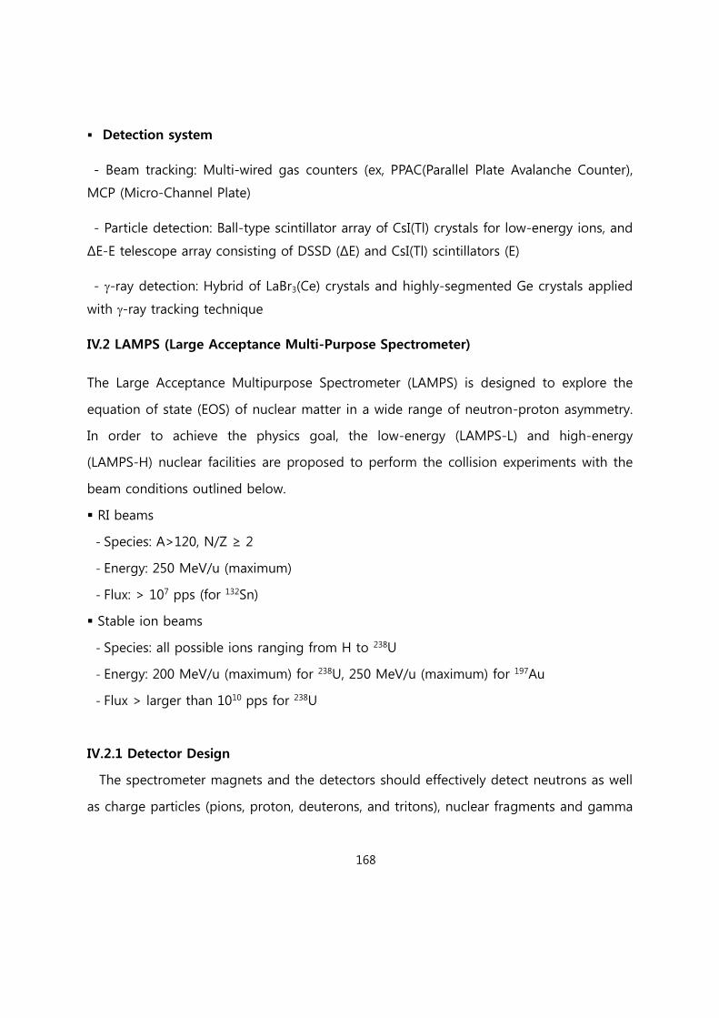
168
Detection system
- Beam tracking: Multi-wired gas counters (ex, PPAC(Parallel Plate Avalanche Counter),
MCP (Micro-Channel Plate)
- Particle detection: Ball-type scintillator array of CsI(Tl) crystals for low-energy ions, and
ΔE-E telescope array consisting of DSSD (ΔE) and CsI(Tl) scintillators (E)
- -ray detection: Hybrid of LaBr3(Ce) crystals and highly-segmented Ge crystals applied
with -ray tracking technique
IV.2 LAMPS (Large Acceptance Multi-Purpose Spectrometer)
The Large Acceptance Multipurpose Spectrometer (LAMPS) is designed to explore the
equation of state (EOS) of nuclear matter in a wide range of neutron-proton asymmetry.
In order to achieve the physics goal, the low-energy (LAMPS-L) and high-energy
(LAMPS-H) nuclear facilities are proposed to perform the collision experiments with the
beam conditions outlined below.
RI beams
- Species: A>120, N/Z ≥ 2
- Energy: 250 MeV/u (maximum)
- Flux: > 107 pps (for 132Sn)
Stable ion beams
- Species: all possible ions ranging from H to 238U
- Energy: 200 MeV/u (maximum) for 238U, 250 MeV/u (maximum) for 197Au
- Flux > larger than 1010 pps for 238U
IV.2.1 Detector Design
The spectrometer magnets and the detectors should effectively detect neutrons as well
as charge particles (pions, proton, deuterons, and tritons), nuclear fragments and gamma
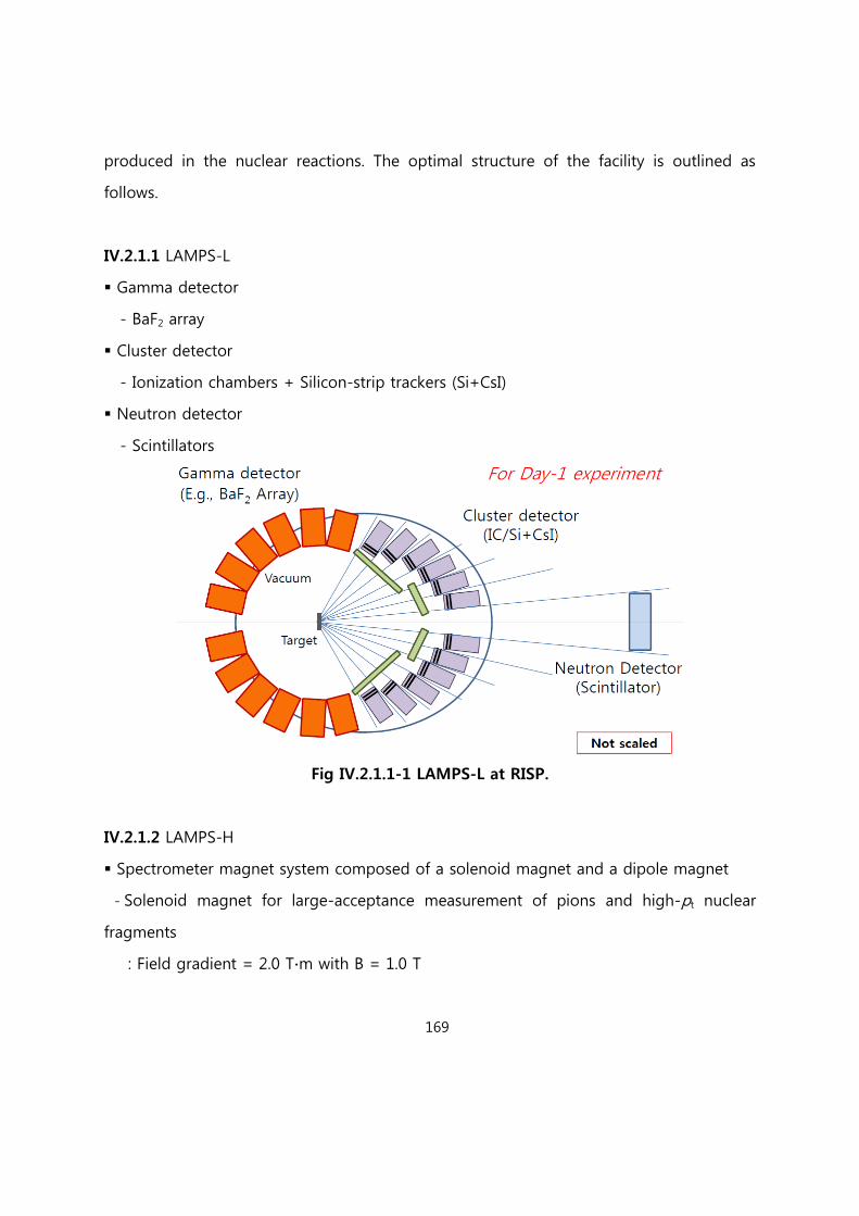
169
produced in the nuclear reactions. The optimal structure of the facility is outlined as
follows.
IV.2.1.1 LAMPS-L
Gamma detector
- BaF2 array
Cluster detector
- Ionization chambers + Silicon-strip trackers (Si+CsI)
Neutron detector
- Scintillators
Fig IV.2.1.1-1 LAMPS-L at RISP.
IV.2.1.2 LAMPS-H
Spectrometer magnet system composed of a solenoid magnet and a dipole magnet
- Solenoid magnet for large-acceptance measurement of pions and high-pt nuclear
fragments
: Field gradient = 2.0 T∙m with B = 1.0 T
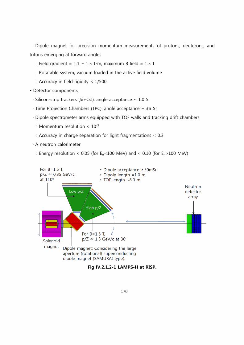
170
- Dipole magnet for precision momentum measurements of protons, deuterons, and
tritons emerging at forward angles
: Field gradient = 1.1 ~ 1.5 T∙m, maximum B field = 1.5 T
: Rotatable system, vacuum loaded in the active field volume
: Accuracy in field rigidity < 1/500
Detector components
- Silicon-strip trackers (Si+CsI): angle acceptance ~ 1.0 Sr
- Time Projection Chambers (TPC): angle acceptance ~ 3π Sr
- Dipole spectrometer arms equipped with TOF walls and tracking drift chambers
: Momentum resolution < 10-3
: Accuracy in charge separation for light fragmentations < 0.3
- A neutron calorimeter
: Energy resolution < 0.05 (for En<100 MeV) and < 0.10 (for En>100 MeV)
Fig IV.2.1.2-1 LAMPS-H at RISP.
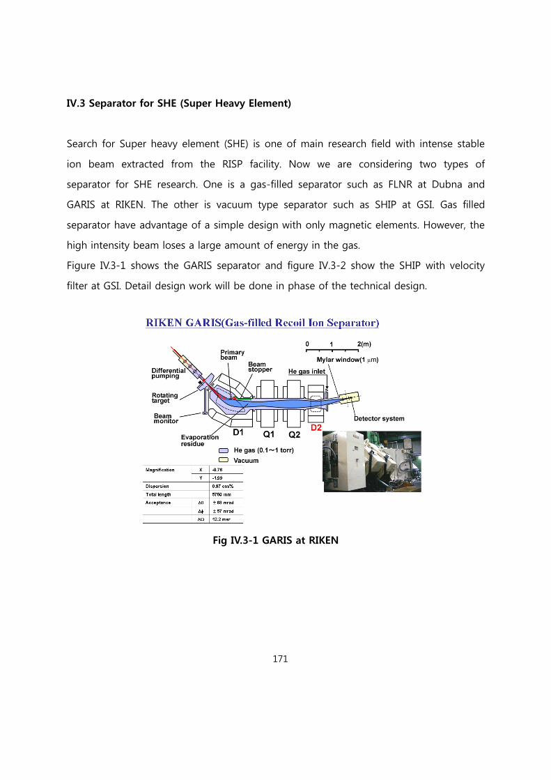
171
IV.3 Separator for SHE (Super Heavy Element)
Search for Super heavy element (SHE) is one of main research field with intense stable
ion beam extracted from the RISP facility. Now we are considering two types of
separator for SHE research. One is a gas-filled separator such as FLNR at Dubna and
GARIS at RIKEN. The other is vacuum type separator such as SHIP at GSI. Gas filled
separator have advantage of a simple design with only magnetic elements. However, the
high intensity beam loses a large amount of energy in the gas.
Figure IV.3-1 shows the GARIS separator and figure IV.3-2 show the SHIP with velocity
filter at GSI. Detail design work will be done in phase of the technical design.
Fig IV.3-1 GARIS at RIKEN
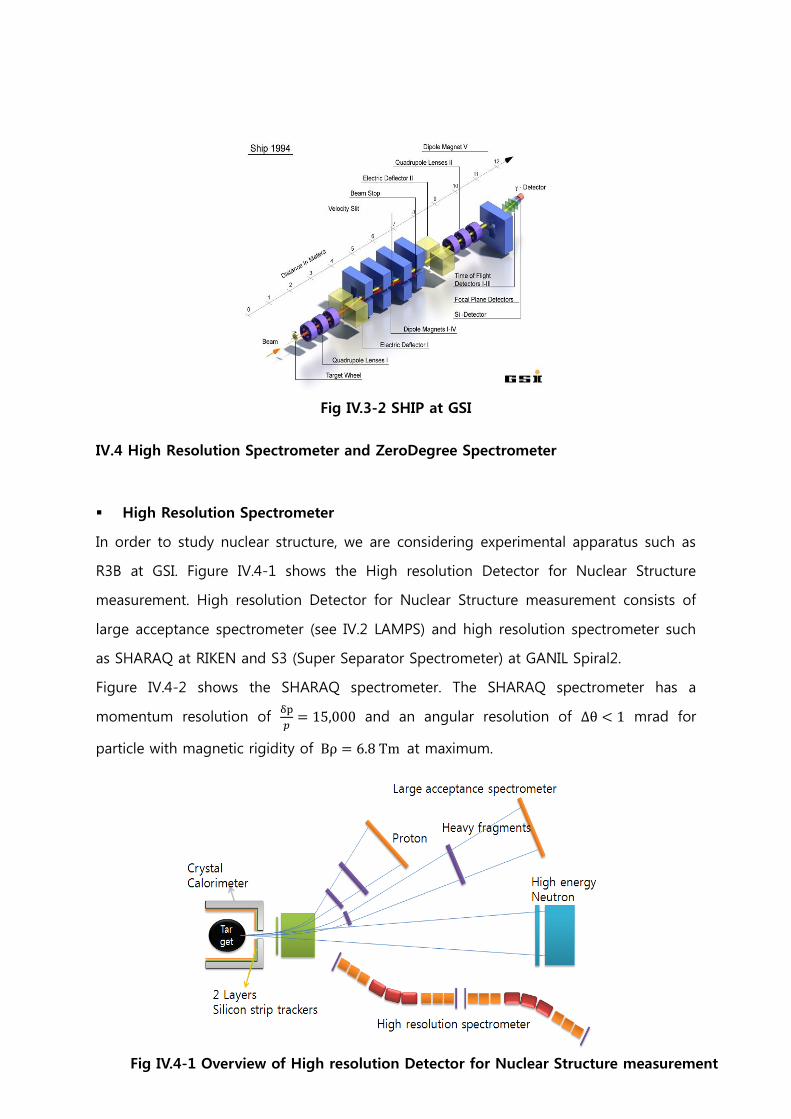
172
Fig IV.3-2 SHIP at GSI
IV.4 High Resolution Spectrometer and ZeroDegree Spectrometer
High Resolution Spectrometer
In order to study nuclear structure, we are considering experimental apparatus such as
R3B at GSI. Figure IV.4-1 shows the High resolution Detector for Nuclear Structure
measurement. High resolution Detector for Nuclear Structure measurement consists of
large acceptance spectrometer (see IV.2 LAMPS) and high resolution spectrometer such
as SHARAQ at RIKEN and S3 (Super Separator Spectrometer) at GANIL Spiral2.
Figure IV.4-2 shows the SHARAQ spectrometer. The SHARAQ spectrometer has a
momentum resolution of
= , and an angular resolution of mrad for
particle with magnetic rigidity of = at maximum.
Fig IV.4-1 Overview of High resolution Detector for Nuclear Structure measurement

173
Fig IV.4-2 Overview of the SHARAQ spectrometer
Figure IV.4-3 shows the S3 separator at GANIL Spiral2. The S3 is a device designed for
experiments with the very high intensity beam. The S3 has a two stage separator
(momentum achromat) and spectrometer (mass spectrometer). The requirements of this
separator are following.
- excellent primary beam suppression (1013 in most case)
- charge state acceptance : ±
- acceptance for each charge state : ±
- maximum magnetic rigidity 1.5 – 2 Tm
- maximum electric rigidity 10 – 12 MV
- mass resolution of 1/300 (FWHM)
Detail design work will be done in phase of the technical design.
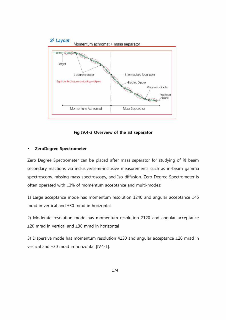
174
Fig IV.4-3 Overview of the S3 separator
ZeroDegree Spectrometer
Zero Degree Spectrometer can be placed after mass separator for studying of RI beam
secondary reactions via inclusive/semi-inclusive measurements such as in-beam gamma
spectroscopy, missing mass spectroscopy, and Iso-diffusion. Zero Degree Spectrometer is
often operated with 3% of momentum acceptance and multi-modes:
1) Large acceptance mode has momentum resolution 1240 and angular acceptance 45
mrad in vertical and 30 mrad in horizontal
2) Moderate resolution mode has momentum resolution 2120 and angular acceptance
20 mrad in vertical and 30 mrad in horizontal
3) Dispersive mode has momentum resolution 4130 and angular acceptance 20 mrad in
vertical and 30 mrad in horizontal [IV.4-1].
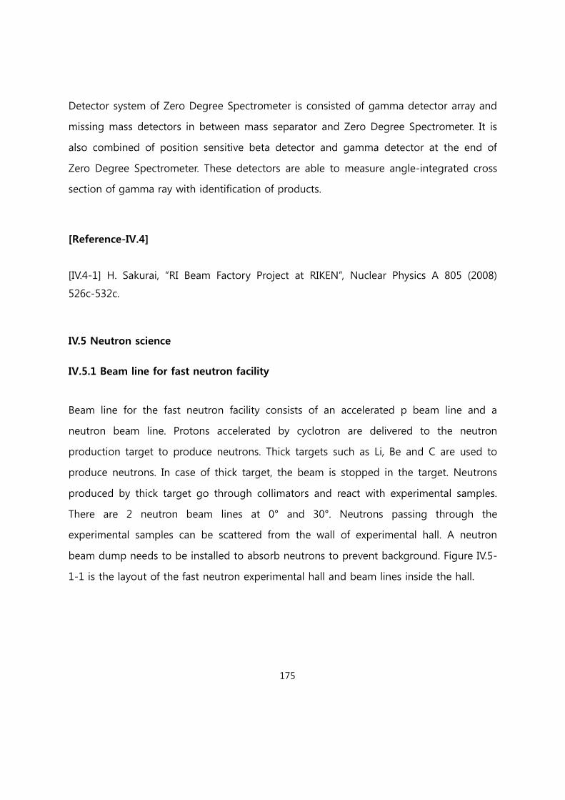
175
Detector system of Zero Degree Spectrometer is consisted of gamma detector array and
missing mass detectors in between mass separator and Zero Degree Spectrometer. It is
also combined of position sensitive beta detector and gamma detector at the end of
Zero Degree Spectrometer. These detectors are able to measure angle-integrated cross
section of gamma ray with identification of products.
[Reference-IV.4]
[IV.4-1] H. Sakurai, “RI Beam Factory Project at RIKEN“, Nuclear Physics A 805 (2008)
526c-532c.
IV.5 Neutron science
IV.5.1 Beam line for fast neutron facility
Beam line for the fast neutron facility consists of an accelerated p beam line and a
neutron beam line. Protons accelerated by cyclotron are delivered to the neutron
production target to produce neutrons. Thick targets such as Li, Be and C are used to
produce neutrons. In case of thick target, the beam is stopped in the target. Neutrons
produced by thick target go through collimators and react with experimental samples.
There are 2 neutron beam lines at 0° and 30°. Neutrons passing through the
experimental samples can be scattered from the wall of experimental hall. A neutron
beam dump needs to be installed to absorb neutrons to prevent background. Figure IV.5-
1-1 is the layout of the fast neutron experimental hall and beam lines inside the hall.
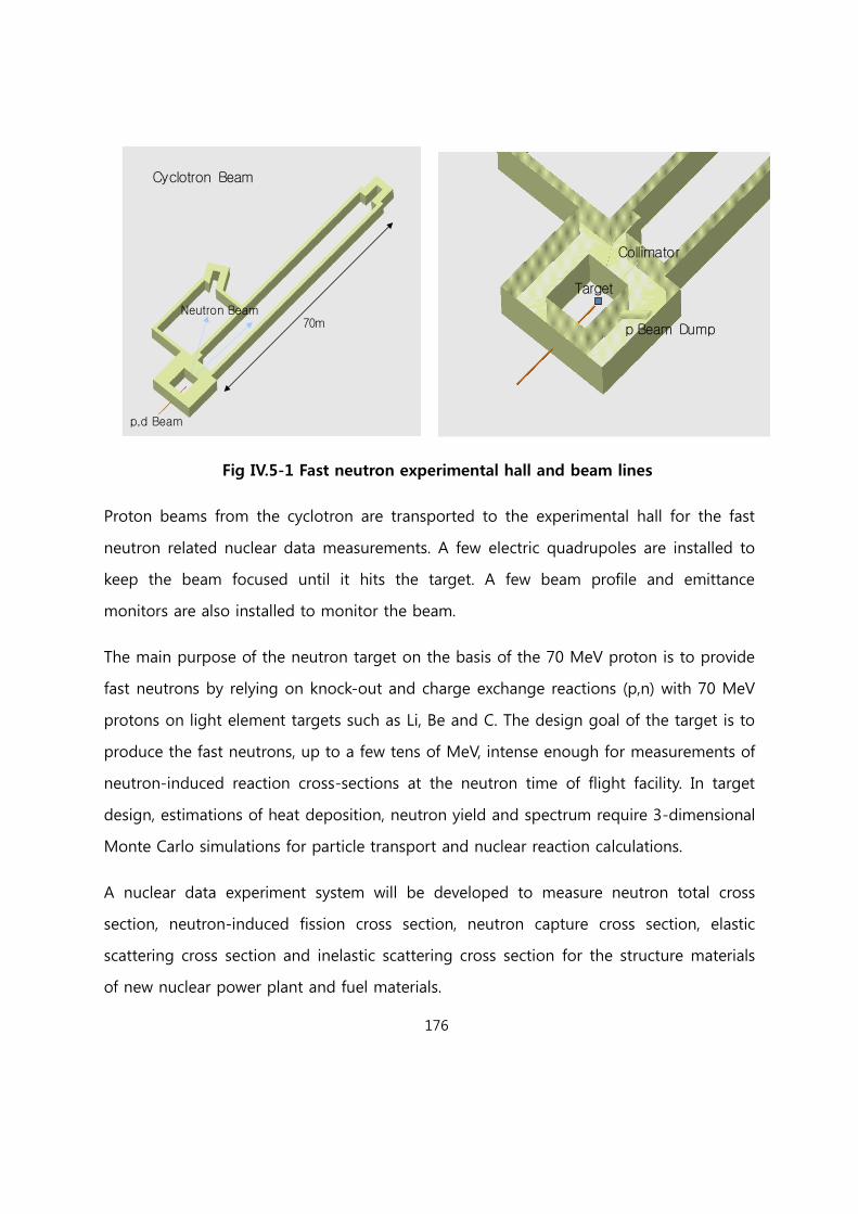
176
Fig IV.5-1 Fast neutron experimental hall and beam lines
Proton beams from the cyclotron are transported to the experimental hall for the fast
neutron related nuclear data measurements. A few electric quadrupoles are installed to
keep the beam focused until it hits the target. A few beam profile and emittance
monitors are also installed to monitor the beam.
The main purpose of the neutron target on the basis of the 70 MeV proton is to provide
fast neutrons by relying on knock-out and charge exchange reactions (p,n) with 70 MeV
protons on light element targets such as Li, Be and C. The design goal of the target is to
produce the fast neutrons, up to a few tens of MeV, intense enough for measurements of
neutron-induced reaction cross-sections at the neutron time of flight facility. In target
design, estimations of heat deposition, neutron yield and spectrum require 3-dimensional
Monte Carlo simulations for particle transport and nuclear reaction calculations.
A nuclear data experiment system will be developed to measure neutron total cross
section, neutron-induced fission cross section, neutron capture cross section, elastic
scattering cross section and inelastic scattering cross section for the structure materials
of new nuclear power plant and fuel materials.
Cyclotron Beam
p,d Beam
70mNeutron Beam
Target
Collimator
p Beam Dump
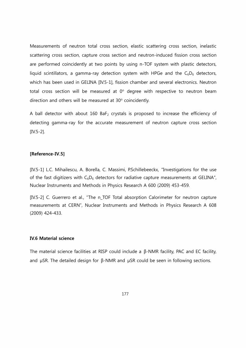
177
Measurements of neutron total cross section, elastic scattering cross section, inelastic
scattering cross section, capture cross section and neutron-induced fission cross section
are performed coincidently at two points by using n-TOF system with plastic detectors,
liquid scintillators, a gamma-ray detection system with HPGe and the C6D6 detectors,
which has been used in GELINA [IV.5-1], fission chamber and several electronics. Neutron
total cross section will be measured at 0o degree with respective to neutron beam
direction and others will be measured at 30o coincidently.
A ball detector with about 160 BaF2 crystals is proposed to increase the efficiency of
detecting gamma-ray for the accurate measurement of neutron capture cross section
[IV.5-2].
[Reference-IV.5]
[IV.5-1] L.C. Mihailescu, A. Borella, C. Massimi, P.Schillebeeckx, “Investigations for the use
of the fast digitizers with C6D6 detectors for radiative capture measurements at GELINA“,
Nuclear Instruments and Methods in Physics Research A 600 (2009) 453-459.
[IV.5-2] C. Guerrero et al., “The n_TOF Total absorption Calorimeter for neutron capture
measurements at CERN”, Nuclear Instruments and Methods in Physics Research A 608
(2009) 424-433.
IV.6 Material science
The material science facilities at RISP could include a β-NMR facility, PAC and EC facility,
and μSR. The detailed design for β-NMR and μSR could be seen in following sections.
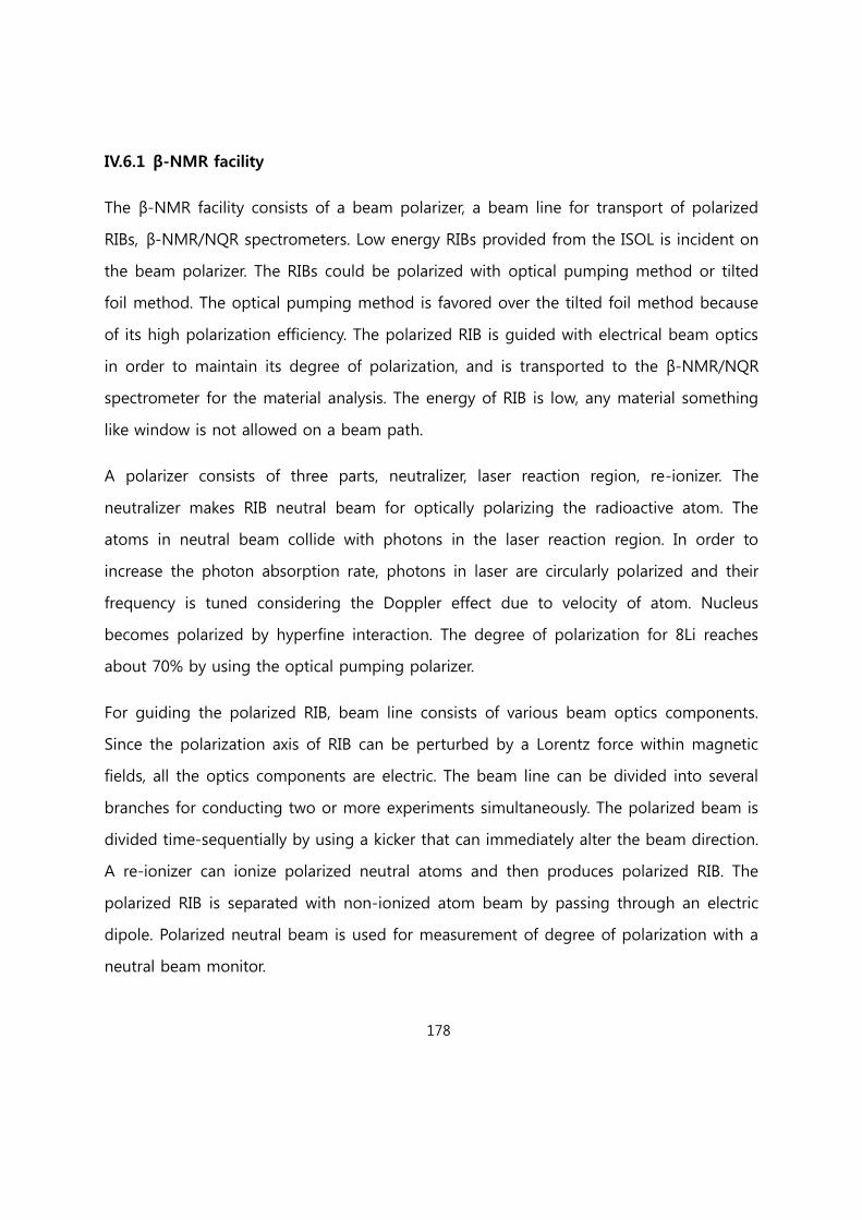
178
IV.6.1 β-NMR facility
The β-NMR facility consists of a beam polarizer, a beam line for transport of polarized
RIBs, β-NMR/NQR spectrometers. Low energy RIBs provided from the ISOL is incident on
the beam polarizer. The RIBs could be polarized with optical pumping method or tilted
foil method. The optical pumping method is favored over the tilted foil method because
of its high polarization efficiency. The polarized RIB is guided with electrical beam optics
in order to maintain its degree of polarization, and is transported to the β-NMR/NQR
spectrometer for the material analysis. The energy of RIB is low, any material something
like window is not allowed on a beam path.
A polarizer consists of three parts, neutralizer, laser reaction region, re-ionizer. The
neutralizer makes RIB neutral beam for optically polarizing the radioactive atom. The
atoms in neutral beam collide with photons in the laser reaction region. In order to
increase the photon absorption rate, photons in laser are circularly polarized and their
frequency is tuned considering the Doppler effect due to velocity of atom. Nucleus
becomes polarized by hyperfine interaction. The degree of polarization for 8Li reaches
about 70% by using the optical pumping polarizer.
For guiding the polarized RIB, beam line consists of various beam optics components.
Since the polarization axis of RIB can be perturbed by a Lorentz force within magnetic
fields, all the optics components are electric. The beam line can be divided into several
branches for conducting two or more experiments simultaneously. The polarized beam is
divided time-sequentially by using a kicker that can immediately alter the beam direction.
A re-ionizer can ionize polarized neutral atoms and then produces polarized RIB. The
polarized RIB is separated with non-ionized atom beam by passing through an electric
dipole. Polarized neutral beam is used for measurement of degree of polarization with a
neutral beam monitor.
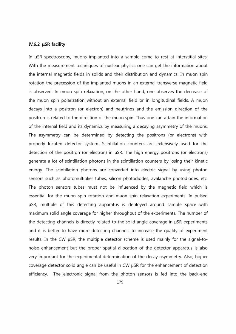
179
IV.6.2 μSR facility
In µSR spectroscopy, muons implanted into a sample come to rest at interstitial sites.
With the measurement techniques of nuclear physics one can get the information about
the internal magnetic fields in solids and their distribution and dynamics. In muon spin
rotation the precession of the implanted muons in an external transverse magnetic field
is observed. In muon spin relaxation, on the other hand, one observes the decrease of
the muon spin polarization without an external field or in longitudinal fields. A muon
decays into a positron (or electron) and neutrinos and the emission direction of the
positron is related to the direction of the muon spin. Thus one can attain the information
of the internal field and its dynamics by measuring a decaying asymmetry of the muons.
The asymmetry can be determined by detecting the positrons (or electrons) with
properly located detector system. Scintillation counters are extensively used for the
detection of the positron (or electron) in µSR. The high energy positrons (or electrons)
generate a lot of scintillation photons in the scintillation counters by losing their kinetic
energy. The scintillation photons are converted into electric signal by using photon
sensors such as photomultiplier tubes, silicon photodiodes, avalanche photodiodes, etc.
The photon sensors tubes must not be influenced by the magnetic field which is
essential for the muon spin rotation and muon spin relaxation experiments. In pulsed
µSR, multiple of this detecting apparatus is deployed around sample space with
maximum solid angle coverage for higher throughput of the experiments. The number of
the detecting channels is directly related to the solid angle coverage in µSR experiments
and it is better to have more detecting channels to increase the quality of experiment
results. In the CW µSR, the multiple detector scheme is used mainly for the signal-to-
noise enhancement but the proper spatial allocation of the detector apparatus is also
very important for the experimental determination of the decay asymmetry. Also, higher
coverage detector solid angle can be useful in CW µSR for the enhancement of detection
efficiency. The electronic signal from the photon sensors is fed into the back-end

180
electronics unit and proper event signals are extracted and the signals which are not
related to the muon decay in the sample are vetoed. After the extraction of the proper
signal from the muon decay in the sample, signal processing electronics unit deduces
the asymmetry of the muon decay and recorded as a result of the experiments. Because
of the short life time of muon (~2.2 µs), the electronics units must process the signal at
high speed for the high throughput of the experiments.
IV.7 Ion trap and Laser spectroscopy
The aim of this facility is to offer precise mass values and spectroscopic information of
rare isotopes for the research fields of particle, nuclear, and astrophysics [IV.7-1].
For highly accurate mass measurement, we need intelligent manipulation of the ions
using a cooler and buncher (RFQ), MR-TOF mass separator, charge breeder ion trap, q/A
selector, preparation and measurement Penning traps, and other beam guiding optics.
Each module should be precisely designed, manufactured, and tested separately for
several years.

181
Fig IV.7-1 Facility design for the mass measurement and laser spectroscopy module.
The facilities for the mass measurement and laser spectroscopy module are drawn
schematically in Fig IV.7-1. Starting with the injection into the RFQ cooler and buncher
before a multi-reflection TOF-MS, the low energy ion beam splits into the dedicated
experimental beam lines of mass measurement and laser spectroscopy. We are also
considering a combined collinear laser spectroscopy setup using one common beam line
as shown in Fig IV.7-2.
Fig IV.7-2 Facility design for a combined collinear laser spectroscopy system at RISP.

182
[Reference IV.7]
[IV.7-1] H.-J. Kluge, Eur. J. Mass Spectrom. 16, 269 (2010).
IV.8 Medical/Bio Science
For the bio and medical science, the new understanding of the interaction between
heavy ion beams and living cells has influenced radiation biology, and may result in a
paradigm shift. For example, the discovery in 1953 of the double-helix model markedly
increased our understanding of DNA structure and function. Therefore, several advances
in biological science using heavy ion beams may have an innovative impact on the
development of biological science. Medical science will result in improving human life
quality by developing new cancer treatment methods and related fields (biology, physics,
pharmacology and mechanical sciences, etc.).
Developing new heavy ion beam therapy methods
Imaging study of heavy ion beam dose distribution
Radioresistance of cancer cells to heavy ion beams
Discovery of new targets and drugs for improving heavy ion beam therapy
Normal tissue damage to heavy ion beams
RBE of heavy ion beam and oxygen dependence
Genomic and proteomic research responsible to heavy ion beam
Neoplastic transformation of cells by heavy ion beam
Epigenetic change by heavy ion beam
Effect of heavy ion beam on embryonic development
Cellular and replica senescence induced by heavy ion beam
DNA damage and repair induced by heavy ion beam
Development of microbial genetic resource for biomass production
Development of variant plant resistant to environmental stresses

183
The aim of medical/bioscience research is to improve human health and quality of life.
Requirements for the medical and bioscience study of world top level:
Isotopes: 8B, 9C, 12C, 11C, 1H, 16O, 2D, 3T, 3He, 4He, 14N, 20Ne, 36Ar, 7Li, 9Be, 11Be, 10B, 27Al,
115In, 28Si, 74Ge, 32S, 197Au, 109Ag, 56Fe, 18F, 35Cl, 125I, 131I , 48Ti, etc.
Energy: 10 ~ 1000 MeV/u
Intensity: 0.1 nA ~ 1 μA
Beam size: 20 μmm2 ~ 900 cm2
Beam direction: both of vertical and horizontal
< 3% dose uncertainty at target position
Dose rate: > 2 Gy/min
Facility design
Low energy
- Irradiation room: one room with horizontal beam, one room with vertical beam
- Other research rooms: cell biology room, facility room, microbiology room, evaluation
room
High energy
- Irradiation room: two rooms with both of vertical and horizontal beams, one room
with horizontal beam for future gantry, one room with horizontal beam for beam test
- Other research rooms: cell biology, facility, animal, evaluation and therapy research
room
IV.9 Elementary Particle Physics
The aim of facility for the elementary particle physics is two-fold. First one is to establish
a fundamental science with EDM search. Second is to look for lepton flavor violation with
muons.

184
-
Fig IV.9-1 Facility design for an EDM search with Ra isotope.
EDM search
The best strategy for EDM search with KoRIA is to study an atomic EDM, in particular,
with Ra ion beam. Figure IV.9-1 shows a design for an EDM search using the laser
cooling technique. It consists of a target station of protons, yielding approximately 108
(225) Ra ions/second [IV.9.1-1]. After passing accumulator and buncher, laser cooling
technique is used to trap Ra ions. At this stage, if a high efficiency is maintained, a
competitive EDM search with Ra ion beam can be achieved.
The main parameters to achieve are the high electric field at the trap region (> 100
kV/cm) and the long coherence time (~ 100 s) of trapped Ra ions. The first atom trap of
radium was realized using oven-based system [IV.9.1-2] and extensive R&D is required to
achieve above parameters.
Lepton flavor violation with muons
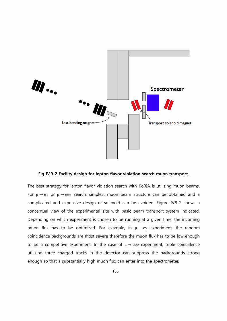
185
Fig IV.9-2 Facility design for lepton flavor violation search muon transport.
The best strategy for lepton flavor violation search with KoRIA is utilizing muon beams.
For μ → eγ or μ → eee search, simplest muon beam structure can be obtained and a
complicated and expensive design of solenoid can be avoided. Figure IV.9-2 shows a
conceptual view of the experimental site with basic beam transport system indicated.
Depending on which experiment is chosen to be running at a given time, the incoming
muon flux has to be optimized. For example, in μ → eγ experiment, the random
coincidence backgrounds are most severe therefore the muon flux has to be low enough
to be a competitive experiment. In the case of μ → eee experiment, triple coincidence
utilizing three charged tracks in the detector can suppress the backgrounds strong
enough so that a substantially high muon flux can enter into the spectrometer.
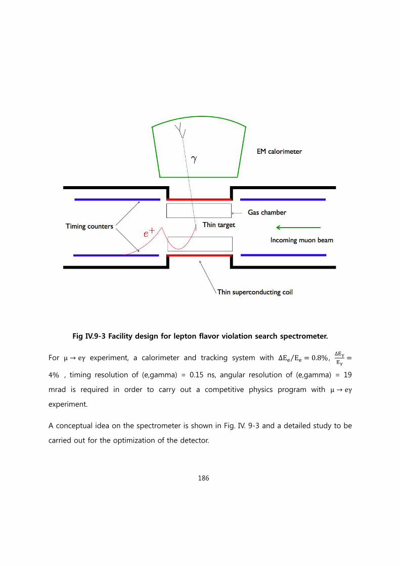
186
Fig IV.9-3 Facility design for lepton flavor violation search spectrometer.
For μ → eγ experiment, a calorimeter and tracking system with Ee Ee = ⁄ , Eγ
Eγ=
4 , timing resolution of (e,gamma) = 0.15 ns, angular resolution of (e,gamma) = 19
mrad is required in order to carry out a competitive physics program with μ → eγ
experiment.
A conceptual idea on the spectrometer is shown in Fig. IV. 9-3 and a detailed study to be
carried out for the optimization of the detector.

187
For μ → eee search, an excellent tracking system is required. A compact tracking system
of silicon sensors or time projection chamber can be used to realize the experiment.
[Reference IV.9]
[IV9.1-1] Private communication with J. C. Yoon, IBS. Efficiencies in various stages are
assumed to be 100%.
[IV9.1-2] Guest et al., Phys. Rev. Lett. 98, 093001 (2007)

188
Chapter V Conventional Facilities
V.1 Site
The accelerator complex will be located in Sindong area that is 14 km away from
downtown of Daejeon city and 11km away from Sejeong special autonomous city. It is
about 4km distance from the planned IBS headquarter. The aerial view of the complex
site is shown in Figure V.1.
Fig. V.1 The aerial view of the accelerator complex site, Sindong area
The accelerator complex will be situated in the north side of the Sindong area and the
total size of the area is 1,049,504m2 (~1,600mx660m). The highest elevation point in the
site is 124m (North West side) and the lowest point is 45m. A creek across the site runs

189
from west to east in the lowest elevation and a power line of 154kV is crossing in the
west side of the site.
V.2 Facilities
The complex should meet all scientific, functional, and operational requirements. It is
comprised of two major areas because of the geographical feature of the site: the
accelerator and experimental area located in the east side and the administration and
supporting area in the west side. The well preserved forest area with a mountain top
(124m) should remain as unaffected and it naturally isolates the office area from
radiation area as shown in the Figure V.2.
Figure V.2 The layout of the accelerator site

190
Preliminary geotechnical data are collected by surface exploration and subsurface
exploration of the site. Soil borings (total 20 points across the site) indicate that most of
the accelerator and experimental area with elevation level of 75m is soft rock so that it
provides solid foundations to linac tunnels and experimental halls. Because the
accelerator tunnels and experimental halls will be positioned relatively high elevation of
75m without crossing a valley, a chance to encounter groundwater is very little. However
further site survey and geotechnical investigations are required during preliminary design
to meet project requirements. The facilities include accelerator buildings, experimental
halls, office building, and support buildings as followings,
Main linac facilities include
Injector area
Linac tunnels
Stripping area
Linac support buildings and support utilities
Target buildings
The ISOL and Re-Accelerator facilities include
Cyclotron and target building
ISOL area
Post-Accelerator linac tunnel
Linac support buildings and support utilities
The support facilities include cryogenic plant and system, high power test building,
superconducting RF facility building, general assembly building, superconducting
cryomodule assembly building, detector R&D and test building, power plant, and etc.
There will be six experimental halls, three for the In-flight fragmented RI beam and three
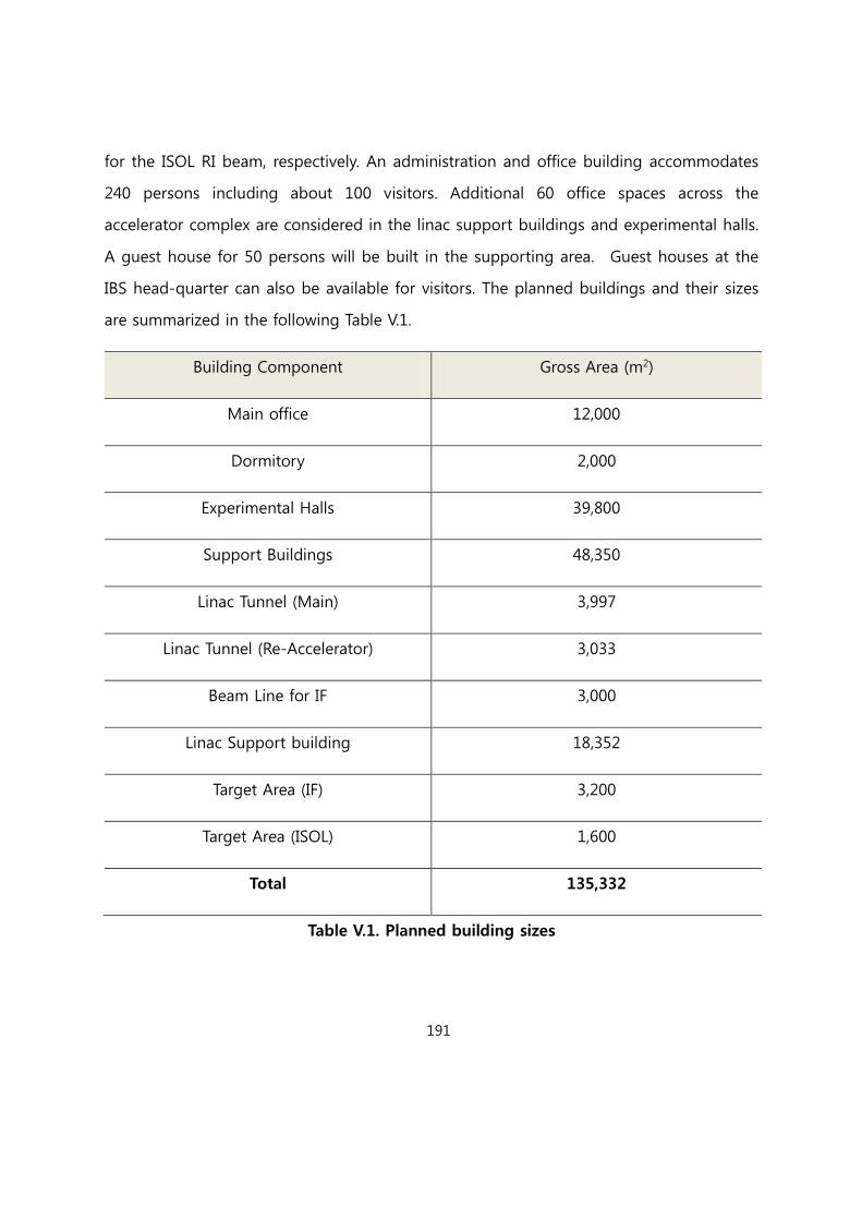
191
for the ISOL RI beam, respectively. An administration and office building accommodates
240 persons including about 100 visitors. Additional 60 office spaces across the
accelerator complex are considered in the linac support buildings and experimental halls.
A guest house for 50 persons will be built in the supporting area. Guest houses at the
IBS head-quarter can also be available for visitors. The planned buildings and their sizes
are summarized in the following Table V.1.
Building Component Gross Area (m2)
Main office 12,000
Dormitory 2,000
Experimental Halls 39,800
Support Buildings 48,350
Linac Tunnel (Main) 3,997
Linac Tunnel (Re-Accelerator) 3,033
Beam Line for IF 3,000
Linac Support building 18,352
Target Area (IF) 3,200
Target Area (ISOL) 1,600
Total 135,332
Table V.1. Planned building sizes

192
V.2.1 Linac tunnel and linac support building
Several structural layouts of linac tunnels and its support buildings are considered and
Figure V.2 configuration is adapted primary. Both driver and post-accelerator linac
tunnels will be in the 14m underground. The linac tunnel will be constructed in cut and
cover method and the gap between linac tunnel and RF gallery floor will be filled with
4m concrete and 4m soil. The linac supporting components will be positioned on the
ground level so that both the structural and cost are optimal. The evaluation of RF and
utility distribution will be performed in the Technical Design Report.
Figure V.3 Proposed linac tunnel and supporting gallery layout

193
V.3 Cryogenic System
The cryogenic system has to be equipped to maintain the performances of
superconducting (SC) cavities and SC magnets in the beam line and experimental
facilities. The cryomodules provide the thermal insulations to SC cavities and SC magnets
against the dynamic loads by the superconducting radio frequency (SRF) and the heat
leakage from the surroundings. Major parts of the cryogenic system are the Helium
Refrigeration System (He Ref), the distribution line and valve boxes, and the cryomodules.
The cryomodules are connected to the He Ref via the vacuum shielded distribution lines.
Fig. V.4 shows a basic concept of the cryogenic system for SC Linac.
Fig. V.4 Cryogenic System Concept
The cooling capacity of He Ref will be decided by the estimated dynamic losses and the
static heat leak from the surroundings into the cryomodules. Experimental results for
prototype cavities are also needed. The static heat leak is calculated from the
cryomodule design and the value will be verified by the prototype cryomodules.

194
The heat loads for all superconducting devices will be estimated and finally minimum He
Ref capacity. Safety factor for the capacity will be at least 50 %. The helium inventory
should be estimated, too. Approximately 50 % of helium will be stored in the
cryomodules.
V.3.1 Helium Refrigeration System (He Ref)
The He Ref is composed of gas helium recovery system, compressor station, cold box
and Buffer Tank for liquid helium and liquid nitrogen. The He Ref supplies helium at
several temperatures; 2 K and 4.5 K liquid helium for the linac cryomodules; 40 K helium
gas for heat shields. Besides, 77 K liquid nitrogen will be used for the heat shields.
2 K helium is delivered by using 2 K modules which contains a 2K/4K heat exchanger
and a Joule-Thomson (J-T) valve. These 2 K modules can be a central one located at the
HRS or smaller modules located at the valve boxes near the cryomodules. The latter
option is preferred by cryogenic experts. SNS have been used the heat exchanger at the
cryomodules and those were proven to be reliable for several years.
Compressor station should be built in a separated building considering its noise level
(around 100 dBA) and vibration. To absorb the vibration marshmallow spring mounted
station will be used.
V.3.1.1 Upgradable HRS option
We should consider how to reduce the construction cost of the HRS due to limited
budget status. In this point of view, upgradable HRS could be an option. For example, if
whole superconducting devices need 15 kW total cooling power including safety margin,
the option includes building 10 - 12 kW HTS firstly; and then attaching 3 - 5 kW
upgradable system (cold box and compressor) secondly to the original one. Fig. V.5
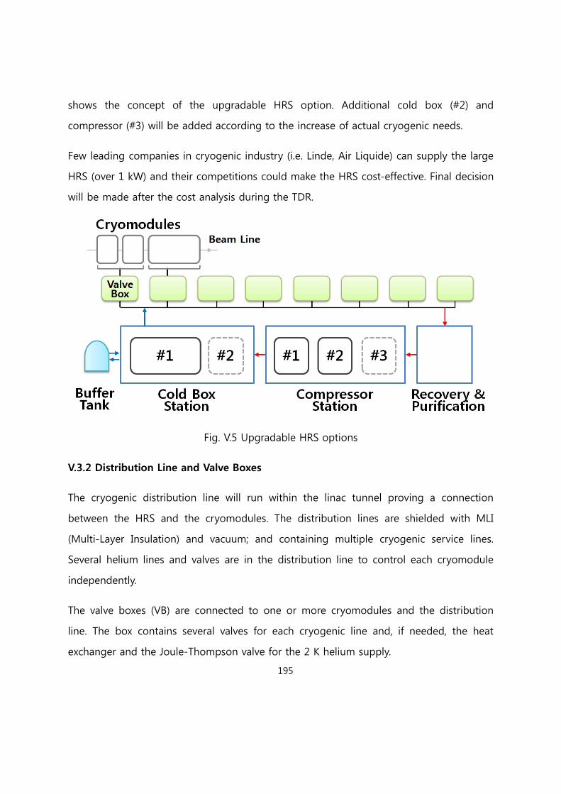
195
shows the concept of the upgradable HRS option. Additional cold box (#2) and
compressor (#3) will be added according to the increase of actual cryogenic needs.
Few leading companies in cryogenic industry (i.e. Linde, Air Liquide) can supply the large
HRS (over 1 kW) and their competitions could make the HRS cost-effective. Final decision
will be made after the cost analysis during the TDR.
Fig. V.5 Upgradable HRS options
V.3.2 Distribution Line and Valve Boxes
The cryogenic distribution line will run within the linac tunnel proving a connection
between the HRS and the cryomodules. The distribution lines are shielded with MLI
(Multi-Layer Insulation) and vacuum; and containing multiple cryogenic service lines.
Several helium lines and valves are in the distribution line to control each cryomodule
independently.
The valve boxes (VB) are connected to one or more cryomodules and the distribution
line. The box contains several valves for each cryogenic line and, if needed, the heat
exchanger and the Joule-Thompson valve for the 2 K helium supply.

196
V.3.3 Vacuum System
The superconducting linac that is transporting heavy ions has cryomodules, each of
which incorporates 1 or more niobium cavities. These cavities are submerged in a bath of
liquid helium and are maintained at an operating temperature of 2 K or 4.5 K. This bath
is surrounded by Multi-layer heat shields. The vacuum level near the beam paths of the
heavy ions needs to be maintained at ~ 10-9 torr (with heavy ion beam, less than 10-8
torr). To keep those ultra-high vacuum levels, a series of careful processes are needed,
such as washing, cleaning, drying and degasing in a vacuum furnace etc. Assembly of the
parts and storage should be done in the clean booth.
Specs of vacuum pumps are decided by the volume of vacuum tubes and the cavities,
desired vacuum level and conductance.
V.4 Electric Power System
Electrical power system for RISP, which will be technically designed with fixing the general
design and P&ID, has been considered as 154kV electrical power receiving facility, AC
power distribution, DC power /UPS, and earth / lightening protection.
154kV electrical power receiving facility
154kV electrical power receiving facility provides the electrical power with the 3.3kV
electrical power plant by reducing the electrical voltage to 3.3kV from 154kV lines
delivered by Korea electrical power company (KEPCO). We have a plan to technically
design by draw a circuit diagram, 154kV driving line, circuit breakers, and transformers

197
and to construct electrical devices, circuit breaker, and alarming system for monitoring
/control for 154kV receiving facility, drawn by electrical logic diagram and connection.
AC electrical power distribution system
AC electrical power distribution system provides 3.3kV, 480V, 220V Ac electrical power
via a receiving transformer from 154kV electrical power plant. To minimize the cost from
an abrupt accident and a power failure and assure the safety for operators, the diesel
generator, connected to AC electrical power distribution system, will be designed to
supply the essential load with emergency lines and UPS power sources.
DC electrical power supply and Uninterrupted Power Supply(UPS)
DC electrical power supplying system, which provides the electrical power with the load
needed to DC power, is composed of capacitors, DC distribution panel, and controls/
monitors for operation. UPS supply the AC power to core elements such as control and
monitors by an electrical power failure from a voltage instability, momentary power
failure, and its accident. We have a plan to construct this sub system, composed of
capacitors, rectifiers, invertors, static automatic or manual switch, variable transformers,
and AC power panels.
Earth and lightening protection
Earth and lightening protection system is to prevent the damage of the workers and
instruments by lightening accident and earth loss in the site, and assure the protection
system from the damaged system. Earth and lightening protection system can supply the

198
stable circuit voltage referred from the earth. Fixing earth type and earth line driving
method divided by the instruments and facilities and setting the protective angle during
lightening protection design process, lightening protection will be located in the storage
of the explosive compounds.
V.5 Radiation Safety
Personal Protection System(PPS)
Personal protection system assures the safety to prevent an abnormal operation and
abrupt accident for the radiation workers and the ordinary person. This system is
classified to and entrance level divided by a risky and alarming structure, and is based on
the following conceptual requirement.
a) Reliability
All components of the PPS should be based on the performance quality assurance and
be assured by a periodic inspection and a sound check of normal operation in advance.
b) Fail-Safe
PPS should be designed to assure the safety during electrical power failure, cable
shortage, and its sensor failure.
c) Redundancy
Central control system and its electrical power of PPS should be constructed with
redundancy.

199
d) Self-diagnostic function
PPS should be supported to an operating test, which can be used a manual or sequential
mode, of each instruments and sensing lines.
e) Simplicity
PPS can be constructed for an easy maintenance and test by simplifying the structure of
the control layer and cables.
f) Prevention to a breakdown of cable insulation
All cables should be inserted in the independent trays to prevent a malfunction of cables
by a radiation and a cable failure by the workers mistakes.
g) Security instruments
The system cannot be modified without releasing the key lock which should be kept by
the manager.
Radiation Monitoring System (RMS)
Radiation Monitoring System can provide a monitoring function to access the facility and
to read out operation status. RMS is composed of both an area monitoring system to
observe the radiation level in the facility of the accelerator and experiment and
environmental radiation monitoring system in the site boundary. We will design and
construct the RMS as following process.

200
a) RMS should be designed to meet the radiation requirement, such as ALALA(as low as
reasonably achievable), for the radiation workers and the ordinary person in the site area.
We are considering the radiation guideline refer to the radiation safety regulations in
Korea.
Reference
①Site boundary 0.25 mSv/yr
②General area in the boundary 0.1 mSv/week (1 mSv/yr)
③Radiation area in the boundary 1 mSv/week (50 mSv/yr)
b) RMS should be monitor the typical system and area which can contain radioactive
materials in the facility and the site boundary. Considering the specification of RMS
can see the following table.
Detectors Sensor type
Detecting
energy
Radiation exposure
Neutron
3-He Proportional
counter
0.025 eV ~
12MeV
1 ~ 1E+4 uSv/hr
Gamma
Pressurized ion
chamber
60 keV ~ 3
MeV
0.1 ~ 1E+5 uSv/hr

201
c) RMS should alarm and record at a high radiation level or electronics failure.
d) When a read out signal is higher than setting value of the radiation level, RMS
should give some information to limit the access of the facility and to turn off the
beam or shut-down the accelerator system.
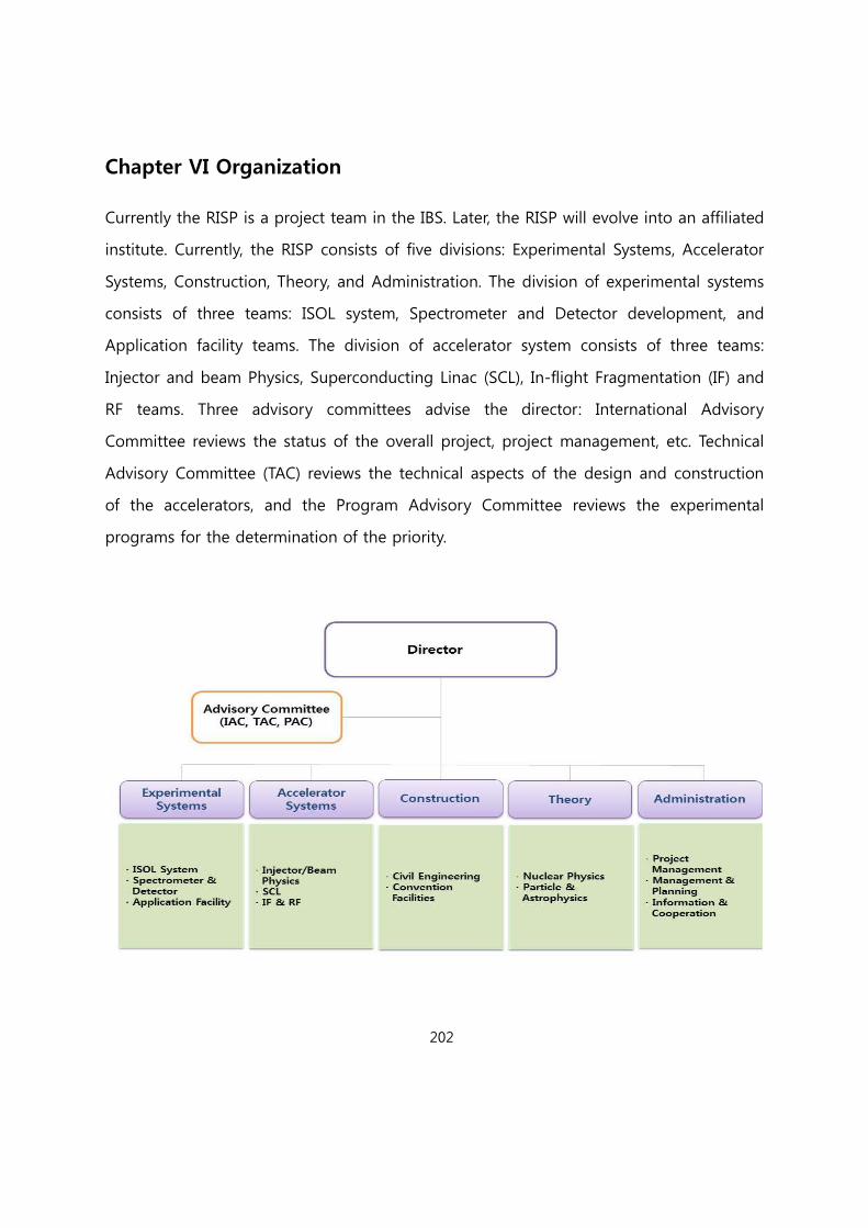
202
Chapter VI Organization
Currently the RISP is a project team in the IBS. Later, the RISP will evolve into an affiliated
institute. Currently, the RISP consists of five divisions: Experimental Systems, Accelerator
Systems, Construction, Theory, and Administration. The division of experimental systems
consists of three teams: ISOL system, Spectrometer and Detector development, and
Application facility teams. The division of accelerator system consists of three teams:
Injector and beam Physics, Superconducting Linac (SCL), In-flight Fragmentation (IF) and
RF teams. Three advisory committees advise the director: International Advisory
Committee reviews the status of the overall project, project management, etc. Technical
Advisory Committee (TAC) reviews the technical aspects of the design and construction
of the accelerators, and the Program Advisory Committee reviews the experimental
programs for the determination of the priority.
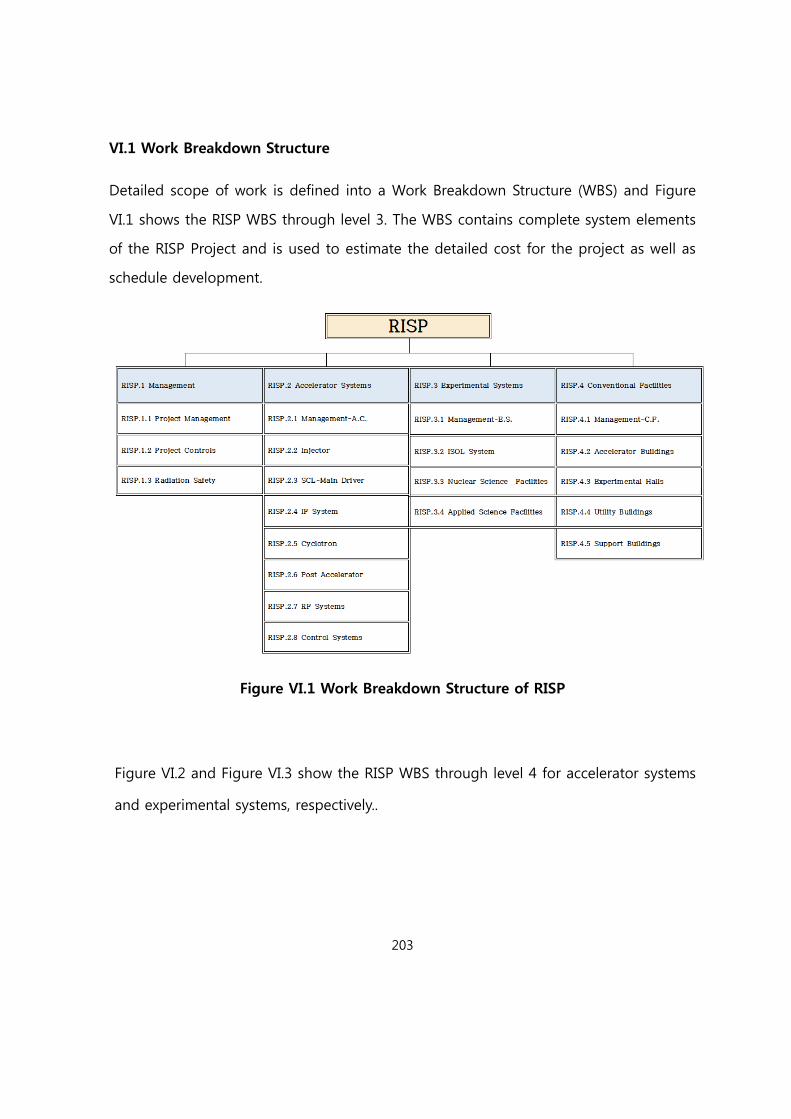
203
VI.1 Work Breakdown Structure
Detailed scope of work is defined into a Work Breakdown Structure (WBS) and Figure
VI.1 shows the RISP WBS through level 3. The WBS contains complete system elements
of the RISP Project and is used to estimate the detailed cost for the project as well as
schedule development.
Figure VI.1 Work Breakdown Structure of RISP
Figure VI.2 and Figure VI.3 show the RISP WBS through level 4 for accelerator systems
and experimental systems, respectively..

204
Figure VI.2 Work Breakdown Structure of Accelerator Systems
Figure VI.3 Work Breakdown Structure of experimental systems
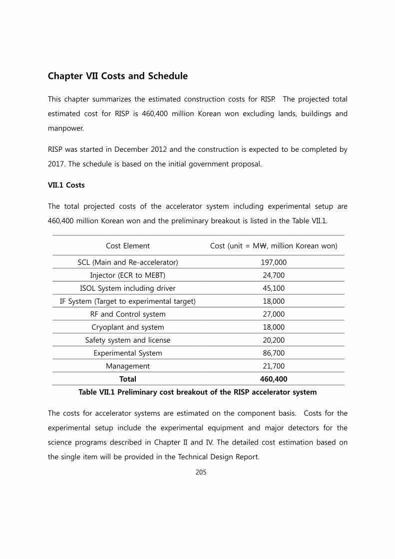
205
Chapter VII Costs and Schedule
This chapter summarizes the estimated construction costs for RISP. The projected total
estimated cost for RISP is 460,400 million Korean won excluding lands, buildings and
manpower.
RISP was started in December 2012 and the construction is expected to be completed by
2017. The schedule is based on the initial government proposal.
VII.1 Costs
The total projected costs of the accelerator system including experimental setup are
460,400 million Korean won and the preliminary breakout is listed in the Table VII.1.
Cost Element Cost (unit = M₩, million Korean won)
SCL (Main and Re-accelerator) 197,000
Injector (ECR to MEBT) 24,700
ISOL System including driver 45,100
IF System (Target to experimental target) 18,000
RF and Control system 27,000
Cryoplant and system 18,000
Safety system and license 20,200
Experimental System 86,700
Management 21,700
Total 460,400
Table VII.1 Preliminary cost breakout of the RISP accelerator system
The costs for accelerator systems are estimated on the component basis. Costs for the
experimental setup include the experimental equipment and major detectors for the
science programs described in Chapter II and IV. The detailed cost estimation based on
the single item will be provided in the Technical Design Report.

206
VII.2 Schedule
The construction schedule is rather tight to complete civil construction and accelerator
installation by February 2018. The construction schedule as shown in the Figure VII.1 is
planned to achieve the goal.
Figure VII.1 Construction schedules for RISP