Based on Lecture Notes by Elza Erkip Digital …eeweb.poly.edu/~yao/EE3414/comm_digital.pdf ·...
28
Yao Wang Polytechnic University, Brooklyn, NY11201 http://eeweb.poly.edu/~yao Digital Communications Principles Based on Lecture Notes by Elza Erkip
Transcript of Based on Lecture Notes by Elza Erkip Digital …eeweb.poly.edu/~yao/EE3414/comm_digital.pdf ·...
Yao WangPolytechnic University, Brooklyn, NY11201
http://eeweb.poly.edu/~yao
Digital Communications Principles
Based on Lecture Notes by Elza Erkip

©Yao Wang, 2006 EE3414: Digital Communications 2
Outline
• Digital Communication Systems– Modulation of digital signals– Error probability vs. SNR– Error correction coding– Channel capacity: noiseless case, and noisy case– Advantages of digital communication
©Yao Wang, 2006 EE3414: Digital Communications 3
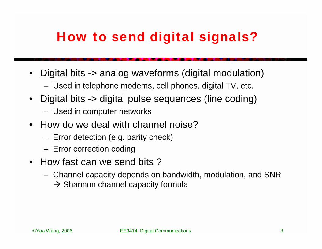
How to send digital signals?
• Digital bits -> analog waveforms (digital modulation)– Used in telephone modems, cell phones, digital TV, etc.
• Digital bits -> digital pulse sequences (line coding)– Used in computer networks
• How do we deal with channel noise?– Error detection (e.g. parity check)– Error correction coding
• How fast can we send bits ? – Channel capacity depends on bandwidth, modulation, and SNR
� Shannon channel capacity formula

©Yao Wang, 2006 EE3414: Digital Communications 4
Modulation of Digital Signals
• For transmission of digital bits over analog channels– Convert group of digital bits into analog waveforms (symbols)– The analog waveforms are formed by adapting the amplitude
and/or phase of a carrier signal (ASK or PSK)– The carrier frequency is chosen based on the
desired/acceptable operating range of the channel– An analog channel of bandwidth B can carry at most 2B
symbols/s. For reduced inter-symbol interference, lower than 2*B symbol rate is used typically
• Shannon’s capacity formula characterizes the dependency of channel capacity on channel bandwidth and noise level
– Equalizer is used at the receiver to reduce the inter-symbol interference

©Yao Wang, 2006 EE3414: Digital Communications 5
A Simple Example
• Digital information: Sequence of 0’s and 1’s: 001101…..• One bit every T seconds. During 0 < t < T
– To send a 0, send – To send a 1, send
• Input signal
• Modulated signal
• This is called Binary Pulse Amplitude Modulation (PAM) or Binary Phase Shift Keying (BPSK).
• For a channel with bandwidth B, T >=1/2B, to avoid inter-symbol interference
)2cos()(0 tfAts cπ=)2cos()(1 tfAts cπ−=
0 0 1 1 0 1

©Yao Wang, 2006 EE3414: Digital Communications 6
Amplitude Shift Keying (ASK)
M-ary ASK: each group of log2M bits generates a symbol. The number corresponding to the symbol controls the amplitude of a sinusoid waveform. The number of cycles in the sinusoid waveform depends on the carrier frequency.(Also known as Pulse Amplitude Modulation or PAM)
4-ASK: 2 bits/symbol (00=-3, 01=-1, 11=1, 10=3)
Example: Given a sequence: 01001011…, what is the analog form resulting from 4-ASK?
Symbol representation: “-1”,”-3”,”3”,”1”
Waveform:
“00”(-3A) “01”(-A) “11” (A) “10”(3A)

©Yao Wang, 2006 EE3414: Digital Communications 7
8-ASK
8-ASK: 3 bits/symbol (000=-7, 001=-5, 011=--3, 010=-1, 110=1, 111=3, 101=5, 100=7)
“001” “011”
“110” “111”
“010”000
“101”“100”
The mapping from bits to symbols are done so that adjacent symbols only vary by 1 bit, to minimize the impact of transmission error (this is called Gray Coding)
©Yao Wang, 2006 EE3414: Digital Communications 8
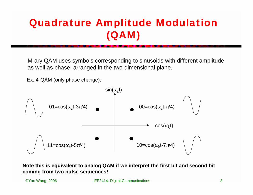
Quadrature Amplitude Modulation (QAM)
M-ary QAM uses symbols corresponding to sinusoids with different amplitude as well as phase, arranged in the two-dimensional plane.
Ex. 4-QAM (only phase change):
sin(ωct)
00=cos(ωct-π/4)01=cos(ωct-3π/4)
11=cos(ωct-5π/4) 10=cos(ωct-7π/4)
cos(ωct)
Note this is equivalent to analog QAM if we interpret the first bit and second bit coming from two pulse sequences!
©Yao Wang, 2006 EE3414: Digital Communications 9
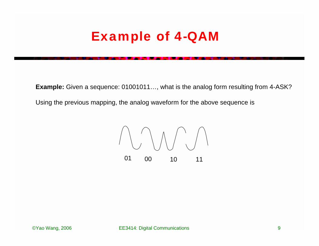
Example of 4-QAM
01 00 10 11
Example: Given a sequence: 01001011…, what is the analog form resulting from 4-ASK?
Using the previous mapping, the analog waveform for the above sequence is

©Yao Wang, 2006 EE3414: Digital Communications 10
16-QAM, etc.
16 QAM (4 bits/symbol): 64-QAM (6 bits/symbol)

©Yao Wang, 2006 EE3414: Digital Communications 11
Vector Representation
• For BPAM, In and the term is common– We can represent s0(t) = A, 0<t<T
s1(t) = -A, 0<t<T
– Or
)(0 ts )(1 ts )2cos( tfcπ
t
s0(t)A
T
s1(t)
-A
Tt
0 A-Ax x1 0
Ex: A digital sequence 100110 is sent as {A –A –A A A –A –A}

©Yao Wang, 2006 EE3414: Digital Communications 12
Vector Representation for ASK
• M-ary ASK (M=4, send two bits at a time)
• Labeling is done in such a way that adjacent points only differ in one bit (called Gray mapping)
A-Ax x xx
-3A 3A
11 10 00 01
Ex: A digital sequence 100010 is sent as {-3A , 5A,…}
Ax xx x
3A 5A 7A-7Ax xx x
-5A -3A -A
8-ASK
111 110 101 011100 001 010 000

©Yao Wang, 2006 EE3414: Digital Communications 13
Two Dimensional Modulation
• Modulated signal – 4-QAM (Quadrature Amplitude Modulation)
– 8-PSK (Phase Shift Keying)
)2sin()2cos()( tfAtfAts cscci ππ +=
xx
xx
x x
xx
A
x
x x
x10 00
0111
AA
A2

©Yao Wang, 2006 EE3414: Digital Communications 14
Parameters of Modulation
• Three important parameters of a modulation scheme:– Minimum distance dmin: The smallest distance among points in
vector representation, which affects error detection capability– Average energy Eav
– Number of bits/symbol= log2(M)
• Example:– 4-ASK: dmin=2A, Eav=2(A2+9A2)/4=5A2, log2(M)=2– 4-QAM: dmin=2A, Eav=2A2, log2(M)=2– For the same Eav and M, we want to maximize dmin (minimize
effect of transmission noise)– For the same dmin and M, we want to minimize Eav (minimize
power consumption)
©Yao Wang, 2006 EE3414: Digital Communications 15
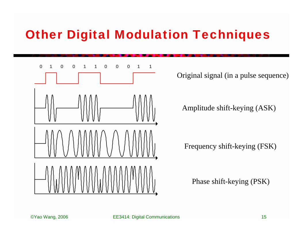
Other Digital Modulation Techniques
0 0 0 00 01 1 1 1 1
Amplitude shift-keying (ASK)
Original signal (in a pulse sequence)
Frequency shift-keying (FSK)
Phase shift-keying (PSK)

©Yao Wang, 2006 EE3414: Digital Communications 16
Effect of noise
• Simple channel: Additive White Gaussian
• Noise n(t) is Gaussian
Modulated Signal +
Noise n(t)
Received Signal
m
σ
22 2/)(
21)sent is /( σ
σπmxemxp −−=
©Yao Wang, 2006 EE3414: Digital Communications 17
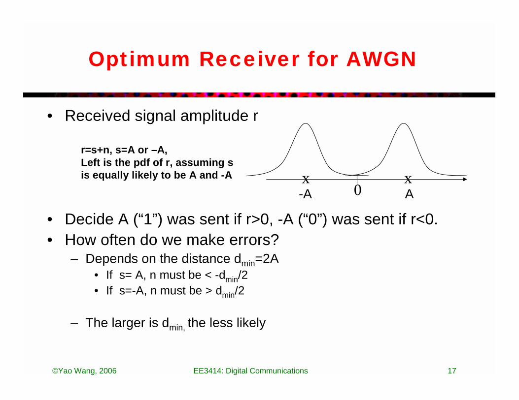
Optimum Receiver for AWGN
• Received signal amplitude r
• Decide A (“1”) was sent if r>0, -A (“0”) was sent if r<0.• How often do we make errors?
– Depends on the distance dmin=2A• If s= A, n must be < -dmin/2• If s=-A, n must be > dmin/2
– The larger is dmin, the less likely
A-Ax x
0
r=s+n, s=A or –A, Left is the pdf of r, assuming s is equally likely to be A and -A
©Yao Wang, 2006 EE3414: Digital Communications 18
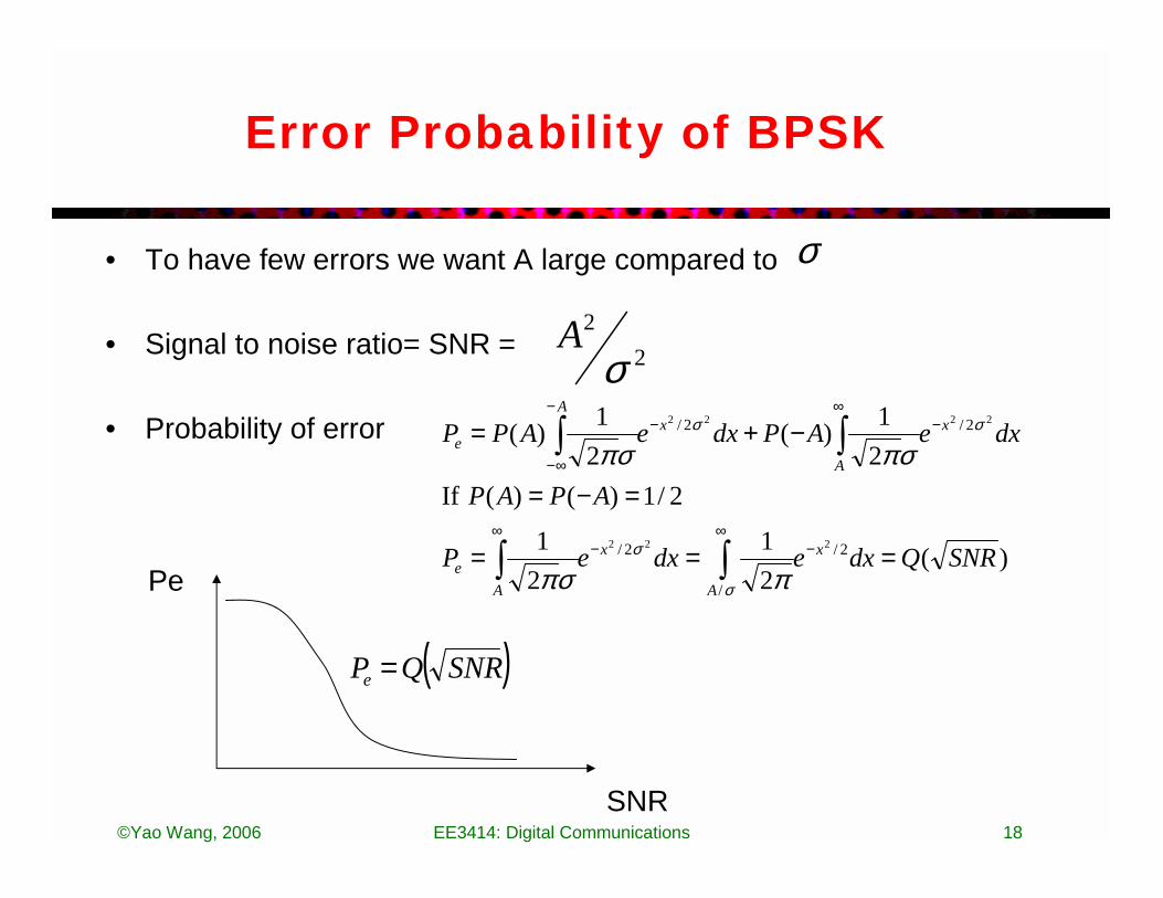
Error Probability of BPSK
• To have few errors we want A large compared to
• Signal to noise ratio= SNR =
• Probability of error
σ
22
σA
)(21
21
2/1)()( If21)(
21)(
2/
/
2/
2/2/
222
2222
SNRQdxedxeP
APAP
dxeAPdxeAPP
x
A
x
Ae
x
A
xA
e
===
=−=
−+=
−∞
−∞
−∞
−−
∞−
∫∫
∫∫
σ
σ
σσ
πσπ
σπσπ
Pe
SNR
( )SNRQPe =

©Yao Wang, 2006 EE3414: Digital Communications 19
Channel Error Detection
• By adding additional bits to the information bits, we can also detect errors
• Parity Check (check-sum)– Append a parity bit to the end of each block (called a frame) of k
information bits such that the total number of '1' is even or odd • Used in IP packet for error detection because of simplicity
• Example:• ASCII "G" = 1 1 1 0 0 0 1• with even parity = append ?• with odd parity = append ?
©Yao Wang, 2006 EE3414: Digital Communications 20
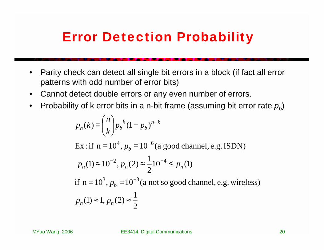
Error Detection Probability
• Parity check can detect all single bit errors in a block (if fact all error patterns with odd number of error bits)
• Cannot detect double errors or any even number of errors. • Probability of k error bits in a n-bit frame (assuming bit error rate pb)
21)2(,1)1(
) wirelesse.g. channel, good sonot a(10,10n if
)1(1021)2(,10)1(
)ISDN e.g. channel, good a(10,10n if :Ex
)1()(
33
42
64
≈≈
==
≤≈≈
==
−
=
−
−−
−
−
nn
b
nnn
b
knb
kbn
pp
p
ppp
p
ppkn
kp

©Yao Wang, 2006 EE3414: Digital Communications 21
Cyclic-Redundancy Codes (CRC)
General Method: • The transmitter generates an t-bit check sequence number from a
given k-bit data frame such that the resulting (k+t)-bit frame is divisible by some number
• The receiver divides the incoming frame by the same number• If the result of the division does not leave a remainder, the receiver
assumes that there was no error• If n is large, undetectable error patterns are very unlikely• Widely used in data communications

©Yao Wang, 2006 EE3414: Digital Communications 22
Error Correction by Channel Coding
• In addition to detect errors, we can correct errors by inserting parity bits. This is called channel coding.
• Simplest channel code: Repetition coding:– Instead of sending one 0, send three 0’s.– If we receive more 0’s than 1’s: Decide 000 was sent– Error probability=3 or 2 bits are wrong=
• =probability of receiving 111,110,101,011• Smaller than Pe• Example: Old Pe=10^-2, New Pe=3*10^-4
– But the information rate is decreased• Instead of R=1bit/sec, we have R=1/3 bits/sec
• More sophisticated channel codes can correct the same number of errors with lower redundancy (less reduction in information rate)
– Block codes (Reed-Solomn codes), convolutional codes, turbo codes
223 3)1(3 eeee PPPP ≈−+
©Yao Wang, 2006 EE3414: Digital Communications 23
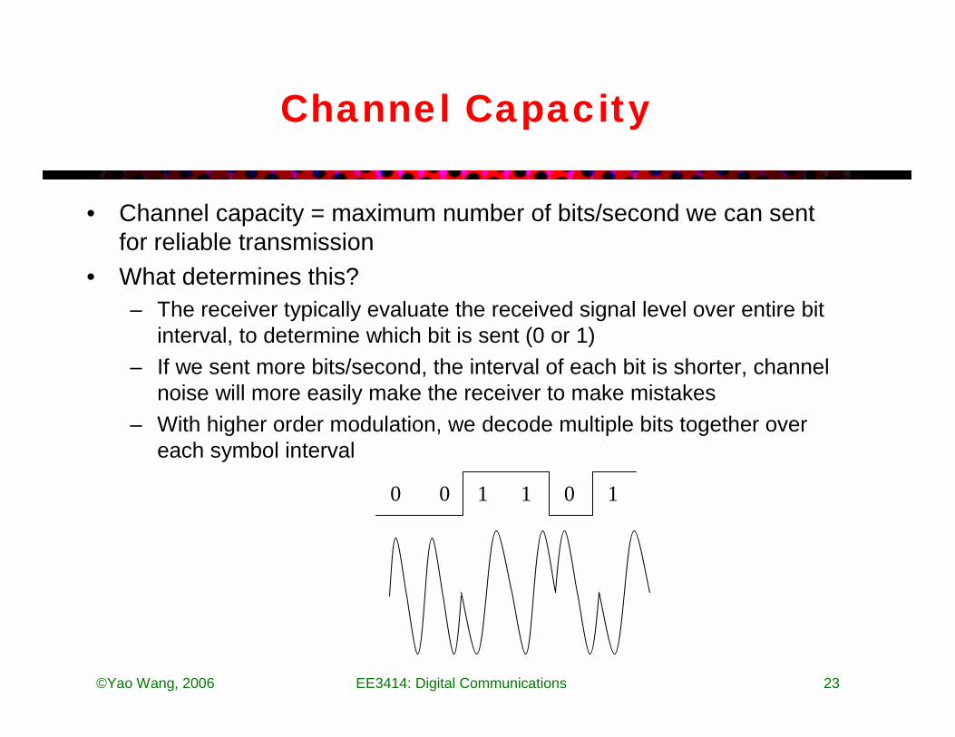
Channel Capacity
• Channel capacity = maximum number of bits/second we can sent for reliable transmission
• What determines this?– The receiver typically evaluate the received signal level over entire bit
interval, to determine which bit is sent (0 or 1)– If we sent more bits/second, the interval of each bit is shorter, channel
noise will more easily make the receiver to make mistakes – With higher order modulation, we decode multiple bits together over
each symbol interval
0 0 1 1 0 1
©Yao Wang, 2006 EE3414: Digital Communications 24
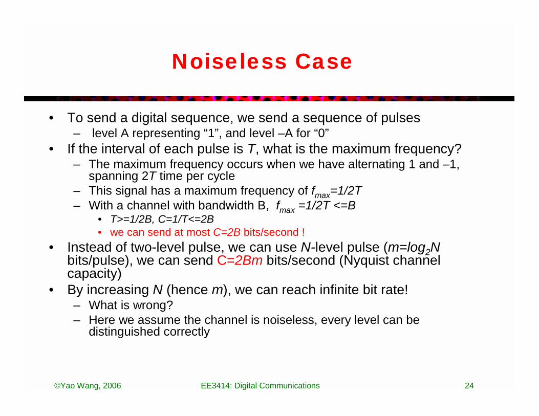
Noiseless Case
• To send a digital sequence, we send a sequence of pulses– level A representing “1”, and level –A for “0”
• If the interval of each pulse is T, what is the maximum frequency?– The maximum frequency occurs when we have alternating 1 and –1,
spanning 2T time per cycle– This signal has a maximum frequency of fmax=1/2T– With a channel with bandwidth B, fmax =1/2T <=B
• T>=1/2B, C=1/T<=2B• we can send at most C=2B bits/second !
• Instead of two-level pulse, we can use N-level pulse (m=log2Nbits/pulse), we can send C=2Bm bits/second (Nyquist channel capacity)
• By increasing N (hence m), we can reach infinite bit rate!– What is wrong?– Here we assume the channel is noiseless, every level can be
distinguished correctly

©Yao Wang, 2006 EE3414: Digital Communications 25
Channel Capacity (Noisy Case)
• When there are more levels in a pulse, the signal difference between two adjacent levels is smaller (for the same total dynamic range). Noise in communication channel is more likely to make the received/detected level differ from the actual level.
• The channel capacity depends on the signal to noise ratio (SNR)– SNR = signal energy / noise energy
• Shannel Channel Capacity– C=B log2 (1+SNR) bits/second
– Ex: B=6MHz, SNR=20 dB = 100, C=?
2 level 4 level
©Yao Wang, 2006 EE3414: Digital Communications 26
Advantages of Digital Communication
• More tolerant to channel noise. – With amplitude shift keying: as long as the noise does not change the
amplitude from one level to another level, the original bits can be inferred
– With QAM: as long as the received signal is more close to the original symbol than its neighboring symbols
– Each repeater can regenerate the analog modulated signals from demodulated bits (noise do not accumulate)
• Can insert parity bits before sending data to allow detection/correction of errors
• Can apply digital compression techniques to reduce data rate subject to distortion criterion
• Different signals can be multiplexed more easily – Internet packets can contain any types of signals, cell phones can send
different types of data
©Yao Wang, 2006 EE3414: Digital Communications 27
What Should You Know
• What is digital modulation?• One and two dimensional modulation schemes• Parameters of digital modulation schemes
– Can calculate basic parameters for a given modulation scheme– Understand the design objective
• Channel error detection and correction– Should understand how simple parity check works and how
repetition coding works• Channel capacity
– Understand the role of channel bandwidth and SNR in determining channel capacity
• Advantages of digital communications

©Yao Wang, 2006 EE3414: Digital Communications 28
References
• A. Leon-Garcia, I. Widjala, Communication networks, Chap 3: Digital transmission fundamentals.