Base station manufacturing test solution
18
Product Brochure Radio Communication Test Station MT8000A Base Station Testing Solution Base Station Test Suite for NR mmWave MX800045A Base Station Test Suite for NR sub-6GHz MX800046A
Transcript of Base station manufacturing test solution

Product Brochure
Radio Communication Test StationMT8000A
Base Station Testing SolutionBase Station Test Suite for NR mmWave MX800045A
Base Station Test Suite for NR sub-6GHz MX800046A

All-in-one Tx power, Frequency error, EVM, ACLR, OBUE, and Rx sensitivity tests for manufacturing both Sub-6 GHz and mmWave base stations
One Main Unit Supports up to 2 slots of RF Modules and Four TRx Ports
The MT8000A incorporates both a signal
analyzer (SA) required for Tx tests and a
signal generator (SG) for Rx tests in one
frame; slots for two RF modules provide
four Sub-6 GHz TRx ports as well as
support connection of four external
mmWave converters for flexible
production-line configurations.
All-in-one Base-station Tester for both Sub-6 GHz and mmWave RF Tests
The all-in-one MT8000A supports Sub-6 GHz
and mmWave RF tests using installed
Sub-6 GHz test modules covering 0.4 GHz to
6 GHz and combination with external
mmWave converters covering 4.25 GHz to
43.5 GHz.
For BTS Manufacturing
MT8000A MX800045A/MX800046A
2

All-in-one Tx power, Frequency error, EVM, ACLR, OBUE, and Rx sensitivity tests for manufacturing both Sub-6 GHz and mmWave base stations
One Main Unit Supports up to 2 slots of RF Modules and Four TRx Ports
The MT8000A incorporates both a signal
analyzer (SA) required for Tx tests and a
signal generator (SG) for Rx tests in one
frame; slots for two RF modules provide
four Sub-6 GHz TRx ports as well as
support connection of four external
mmWave converters for flexible
production-line configurations.
All-in-one Base-station Tester for both Sub-6 GHz and mmWave RF Tests
The all-in-one MT8000A supports Sub-6 GHz
and mmWave RF tests using installed
Sub-6 GHz test modules covering 0.4 GHz to
6 GHz and combination with external
mmWave converters covering 4.25 GHz to
43.5 GHz.
For BTS Manufacturing
MT8000A MX800045A/MX800046A
3
4
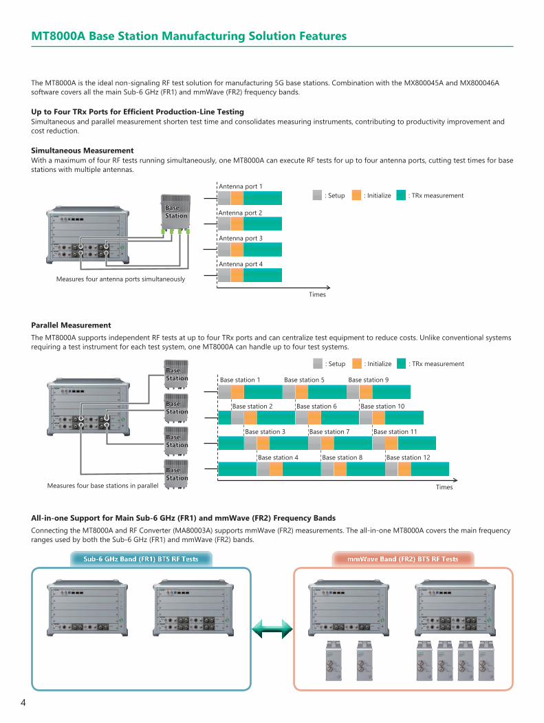
The MT8000A is the ideal non-signaling RF test solution for manufacturing 5G base stations. Combination with the MX800045A and MX800046A software covers all the main Sub-6 GHz (FR1) and mmWave (FR2) frequency bands.
Up to Four TRx Ports for Efficient Production-Line TestingSimultaneous and parallel measurement shorten test time and consolidates measuring instruments, contributing to productivity improvement and cost reduction.
Simultaneous MeasurementWith a maximum of four RF tests running simultaneously, one MT8000A can execute RF tests for up to four antenna ports, cutting test times for base stations with multiple antennas.
Measures four antenna ports simultaneously
Antenna port 1
Times
Antenna port 2
Antenna port 3
Antenna port 4
Base StationBase Station
: Setup : Initialize : TRx measurement
Parallel MeasurementThe MT8000A supports independent RF tests at up to four TRx ports and can centralize test equipment to reduce costs. Unlike conventional systems requiring a test instrument for each test system, one MT8000A can handle up to four test systems.
Measures four base stations in parallel
Base station 1
Times
Base station 2
Base station 3
Base station 4
Base station 5
Base station 6
Base station 7
Base station 8
Base station 9
Base station 10
Base station 11
Base station 12
Base StationBase Station
Base StationBase Station
Base StationBase Station
Base StationBase Station
: Setup : Initialize : TRx measurement
All-in-one Support for Main Sub-6 GHz (FR1) and mmWave (FR2) Frequency BandsConnecting the MT8000A and RF Converter (MA80003A) supports mmWave (FR2) measurements. The all-in-one MT8000A covers the main frequency ranges used by both the Sub-6 GHz (FR1) and mmWave (FR2) bands.
Sub-6 GHz Band (FR1) BTS RF Tests mmWave Band (FR2) BTS RF Tests
MT8000A Base Station Manufacturing Solution Features

5
The Base Station Test Suite for NR mmWave MX800045A/Base Station Test Suite for NR sub-6GHz MX800046A are non-signaling RF test software for production-line testing of 5G NR base stations. They analyze downlink signals and measure RF characteristics for the 5G NR-specified Sub-6 GHz (FR1) and mmWave (FR2) bands.
All-at-Once Multiple Test ItemsThe MX800045A/MX800046A software can measure multiple test items in all at once for frequency error, EVM, ACLR, OBUE, etc.
All-at-Once Multiple Component Carrier MeasurementThe MX800045A/MX800046A software helps to cut test time by measuring multiple component carrier(CC)s in all at once, not measuring each CC one by one.
Name/Model Sub-carrier Spacing Channel BandwidthMaximum Number of Component
Carriers
Base Station Test Suite for NR mmWaveMX800045A
120 kHz
100 MHz 8
200 MHz 4
400 MHz 2
Base Station Test Suite for NR sub-6GHzMX800046A
15 kHz 20 MHz2
30 kHz 20, 40, 60, 80, 100 MHz
Features of Base Station Test Suite for NR mmWave MX800045A/ Base Station Test Suite for NR sub-6GHz MX800046A

6
Easy-to-See GUI for Better Measurement EfficiencyGraphs and tables of measurement results as well as individual measurement result summaries and details can be switched by one-button operation for efficient results confirmation. Other convenient functions, such as parameter bookmarking improve parameter setting efficiency.
Summary and Details Display Switching
One-button switching between results summary and details displays
BookmarkingRegistering frequently used parameters as bookmarked settings cuts parameter setting search times for more efficient measurement.
Bookmark frequently used parameters
Set bookmarked parameters
Features of Base Station Test Suite for NR mmWave MX800045A/ Base Station Test Suite for NR sub-6GHz MX800046A

7
List of Measurement and Signal Generation FunctionsName/Model Base Station Test Suite for NR mmWave MX800045ASupported Standards 3GPP TS 38.141-2 V15.4.0 (2019-12)TRX Port Mode Signal Analyzer Signal Generator
Frequency Setting RangeMA80003A connected24.25 GHz to 29.5 GHz37 GHz to 43.5 GHz
Supported Measurements
6. Radiated transmitter characteristics- 6.2 Radiated transmit power- 6.3 OTA base station output power- 6.4 OTA output power dynamics- 6.6.2 OTA frequency error- 6.6.3 OTA modulation quality- 6.6.4 OTA time alignment error- 6.7.2 OTA occupied bandwidth- 6.7.3 OTA ACLR- 6.7.4 OTA OBUE
7. Radiated receiver characteristics- 7.3 OTA Reference sensitivity level
Downlink SignalNR-FR2-TM1.1NR-FR2-TM2NR-FR2-TM3.1
Uplink Signal —G-FR2-A1-2G-FR2-A1-3G-FR2-A1-5
Supported Physical Channels PDCCH, PDSCH PDCCH, PDSCHPUSCH
Supported Modulation Methods QPSK, 16QAM, 64QAM, 256QAM, Auto QPSK, 16QAM, 64QAM, 256QAM
Name/Model Base Station Test Suite for NR sub-6GHz MX800046ASupported Standards 3GPP TS 38.141-1 V15.4.0 (2019-12)TRX Port Mode Signal Analyzer Signal GeneratorFrequency Setting Range 400 MHz to 6 GHz
Supported Measurements
6. Transmitter characteristics- 6.2 BS output power- 6.3.3 Total power dynamic range- 6.5.2 Frequency error- 6.5.3 Modulation quality- 6.5.4 Time alignment error- 6.6.2 Occupied bandwidth- 6.6.3 ACLR- 6.6.4 Operating band unwanted emissions
7. Receiver characteristics- 7.2 Reference sensitivity level
Downlink Signal
NR-FR1-TM1.1NR-FR1-TM1.2NR-FR1-TM2NR-FR1-TM2aNR-FR1-TM3.1NR-FR1-TM3.1aNR-FR1-TM3.2NR-FR1-TM3.3
Uplink Signal —
G-FR1-A1-1G-FR1-A1-2G-FR1-A1-4G-FR1-A1-5G-FR1-A1-7G-FR1-A1-8
Supported Physical Channels PDCCH, PDSCH PDCCH, PDSCHPUSCH
Supported Modulation Methods QPSK, 16QAM, 64QAM, 256QAM, Auto QPSK, 16QAM, 64QAM, 256QAM
Numeric ResultsName Units Remarks
Tx Power dBm Displays Tx powerFreq. Error Hz/ppm Displays frequency errorEVM (Total) % (rms) Displays EVM rms
Time Offset ns
Displays Frame header and trigger time difference in ns unitsWhen using external Frame trigger, displays measurement results at SA Trigger = On
OBUE Pass/Fail display
Displays Pass/Fail at Summary displayDisplays unwanted emission Level (dBm), Mask Margin (dB), Frequency (MHz) at Details display
ACLR dBc Displays adjacent channel leakage power ratio
Graph DisplaysName Main Screen
ACLR
FundamentalEVM
Constellation
Spectrum Monitor Spectrum Monitor
Features of Base Station Test Suite for NR mmWave MX800045A/ Base Station Test Suite for NR sub-6GHz MX800046A
8
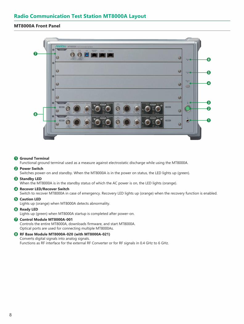
Radio Communication Test Station MT8000A Layout
MT8000A Front Panel
1
2
3
4
5
6
7
1 Ground TerminalFunctional ground terminal used as a measure against electrostatic discharge while using the MT8000A.
2 Power SwitchSwitches power-on and standby. When the MT8000A is in the power on status, the LED lights up (green).
3 Standby LEDWhen the MT8000A is in the standby status of which the AC power is on, the LED lights (orange).
4 Recover LED/Recover SwitchSwitch to recover MT8000A in case of emergency. Recovery LED lights up (orange) when the recovery function is enabled.
5 Caution LEDLights up (orange) when MT8000A detects abnormality.
6 Ready LEDLights up (green) when MT8000A startup is completed after power-on.
7 Control Module MT8000A-001Controls the entire MT8000A, downloads firmware, and start MT8000A. Optical ports are used for connecting multiple MT8000As.
8 RF Base Module MT8000A-020 (with MT8000A-021)Converts digital signals into analog signals.Functions as RF interface for the external RF Converter or for RF signals in 0.4 GHz to 6 GHz.
8

9
Radio Communication Test Station MT8000A Layout
MT8000A Modules
1 Sync Input Connector (Not used in MX800045A/MX800046A)BNC connector for inputting synchronizing signal.
2 Sync Output Connector (Not used in MX800045A/MX800046A)BNC connector for outputting synchronizing signal.
3 USB Connector (Not used in MX800045A/MX800046A)USB (Type B) connector to connect the external PC.
Control Module MT8000A-001
1 2 3 4 5 6
4 Application Server Connector (Not used in MX800045A/MX800046A)RJ-45 connector to connect the external PC for Application Server.
5 Control ConnectorRJ-45 connector for connecting the MT8000A and Control PC.
6 Ethernet Connector (Not used in MX800045A/MX800046A)RJ-45 connector for connecting the external PC, etc.
RF Base MT8000A-020
1 TRX Switch 1 ConnectorBNC connector that outputs signals to control the external amplifier, etc.
2 RF Converter 1 A1 ConnectorMulti-contact connector that controls the external RF Converter.
3 RF Converter 1 B1 ConnectorN connector that input/output the external RF Converter and RF signals.
1 2 3 4 5 6
4 TRX Switch 2 ConnectorBNC connector that outputs signals to control the external amplifier, etc.
5 RF Converter 2 A2 ConnectorMulti-contact connector that controls the external RF Converter.
6 RF Converter 2 B2 ConnectorN connector that inputs/outputs the RF signals between the external RF Converter and MT8000A.
RF Base Module MT8000A-020 + 0.4 GHz-6 GHz RF Sub Module MT8000A-021
1 TRX Switch 1 connectorBNC connector that outputs signals to control the external amplifier, etc.
2 RF Converter 1 A1 connectorMulti-contact connector that controls the external RF Converter.
3 RF Converter 1 B1 connectorN connector that input/output the external RF Converter and RF signals.
4 TRX Switch 2 connectorBNC connector that outputs signals to control the external amplifier, etc.
5 RF Converter 2 A2 connectorMulti-contact connector that controls the external RF Converter.
6 RF Converter 2 B2 connectorN connector that inputs/outputs the RF signals between the external RF Converter and MT8000A.
1 2 3 4 5 67 8 9 10
7 6 GHz RF1 Aux 1 connectorRF auxiliary connector (output) when 0.4 GHz-6 GHz RF Sub Module option is installed.
8 6 GHz RF1 Main 1 connectorRF main connector (input/output) when 0.4 GHz-6 GHz RF Sub Module option is installed.
9 6 GHz RF2 Aux 2 connectorRF auxiliary connector (output) when 0.4 GHz-6 GHz RF Sub Module option is installed.
10 6 GHz RF2 Main 2 connectorRF main connector (input/output) when 0.4 GHz-6 GHz RF Sub Module option is installed.
Note: The frequency range indicated on the panel is “0.4 GHz-6 GHz” when 0.4 GHz-6 GHz RF Sub Module MT8000A-021 is installed. RF Converter 1 and RF Converter 2 cannot be used simultaneously with 6 GHz RF 1 and 6 GHz RF 2 respectively.

10
Radio Communication Test Station MT8000A Layout
MT8000A Rear Panel
1
2
3
4 5 6 7 8
9
10
1 Power InletPower cable connector for 100 VAC to 120 VAC or 200 VAC to 240 VAC (50 Hz/60 Hz) (auto-switching). Power consumption: 1500 VA or less.
2 IdentificationLabelIdentifies the manufacturer of laser products.
3 CertificationLabelCertifies that the MT8000A conforms to 21 CFR 1040.10 AND 1040.11 except Laser Notice No.50.
4 Ethernet Connector for Measure (3 and 4 do not use MX800045A/MX800046A)RJ-45 connector for measurement.
5 Expansion Connector (Not used in MX800045A/MX800046A)Used for input/output of trigger signals.
6 Aux Connector (Not used in MX800045A/MX800046A)Auxiliary connector to output frame timing signals.
7 Event Trigger Input Connector (3 and 4 do not use MX800045A/MX800046A)BNC connector to input event triggers from external devices. Can input event trigger signals of 4 systems.
8 Event Trigger Output Connector (Not used in MX800045A/MX800046A)BNC connector to output event triggers to external devices. Can output event trigger signals of 4 systems. Can be used also as output of ARB marker.
9 Reference signal input connectorBNC connector to input 10 MHz reference signal from external devices.
10 Reference Signal Output ConnectorBNC connector to output 10 MHz reference signal built in the MT8000A.
11 Safety LabelWARNING label for safe operation of MT8000A. Observe the description on the label.
11

11
Selection Guide
Model NameSub-6 GHz mmWave
1,2 ports 3, 4 ports 1 port 2 port 4 port
MT8000A Radio Communication Test Station
MT8000A-001*1 Control Module
MT8000A-020*2 RF Base Module
MT8000A-021*3 0.4 GHz-6 GHz RF Sub Module
MA80003A Multiband RF Converter
MX800045A Base Station Test Suite for NR mmWave
MX800046A Base Station Test Suite for NR sub-6GHz
MX800045A-SS101*4 Base Station Test for 5G NR mmWave Support Service (Per Year)
MX800046A-SS101*5 Base Station Test for 5G NR sub-6GHz Support Service (Per Year)
*1: Required option.*2: Two Multiband RF Converter MA80003A units can be connected to one module.*3: Requires MT8000A-020 option. One module has two built-in RF TRx ports.*4: Recommend ordering at same time as MX800045A.*5: Recommend ordering at same time as MX800046A.

12
Radio Communication Test Station MT8000A Specifications
Radio Communication Test Station MT8000A
Reference Oscillator
Reference frequency: 10 MHzStart-up characteristics: ±5 × 10⁻⁸ (3 min. after power-on. Referenced to frequency 1 hour after power-on)Aging rate: ±1 × 10⁻⁸/day (referenced to frequency 48-hour after power-on)
±1 × 10⁻⁷/year (referenced to frequency 10-day after power-on)Temperature characteristics: ±2 × 10⁻⁸
Frequency adjusted at shipment: ±2.2 × 10⁻⁸ (+18°C to +28°C, referenced to frequency 1 hour after power-on)10 MHz Buffer Output
Frequency: 10 MHz Connector: BNC (f) Impedance: 50Ω (nom.) Output Level: ≥0 dBm (AC coupling)
10 MHz Ref Input Frequency: 10 MHz Operating range: ±1 ppm Connector: BNC (f) Impedance: 50Ω (nom.) Input level: –15 dBm ≤ level ≤ +20 dBm (AC coupling)
External Interface
MEAS 1 to 4: RJ45, 1000Base-T, for slot 1 to 4Event TRIG Input 1 to 4: BNC (f), LVTTLEvent TRIG/ARB Maker Output 1 to 4: BNC (f), 3.3 V LVCMOSExpansion 1, 2: DX20A (3.3 V LVCMOS)Aux: DX20A (3.3 V LVCMOS)
Power Supply
Rated voltage: 100 VAC to 120 VAC/200 VAC to 240 VAC (Operating voltage is –15%/+10% of rated voltage, however, lower limit is 90 V, upper limit is 250 V)
Rated frequency: 50 Hz/60 HzPower consumption: ≤1500 VA (include all options and modules)
Dimensions and MassDimensions: 426 (W) × 265 (H) × 578 (D) mm (excluding projections)Mass: ≤50 kg (including all options)
Environmental ConditionsOperating temperature range: +5°C to +40°C (without condensation)Storage temperature: –20°C to +71°C (without condensation)
CE
EMC 2014/30/EU, EN61326-1, EN61000-3-2
LVD 2014/35/EU, EN61010-1
RoHS 2011/65/EU, (EU) 2015/863, EN IEC 63000: 2018
Laser Safety*IEC 60825-1 Class 1FDA 21CFR1040.10 and 1040.11 Excludes deviations caused by conformance to LASER Notice No.50 dated June 24, 2007
*: Safety measures for laser products This option complies with optical safety standards in IEC 60825-1, 21CFR1040.10 and 1040.11; the following descriptive labels are affixed to the product.
Control Module MT8000A-001
External Interface
USB: USB (Type-B)Application Server: RJ-45 (1000Base-T)Control: RJ-45 (1000Base-T)Ethernet: RJ-45 (1000Base-T)Sync Input: BNC (f) (LVTTL)Sync Output: BNC (f) (3.3 V LVCMOS)
RF Base Module MT8000A-020
IF Input/Output ConnectorRF Converter B1, B2
Connector: N (f)Impedance: 50Ω (nom.)
External InterfaceRF Converter A1, A2: Round multiway type connectorTRX Switch 1, 2: BNC (f) (3.3 V LVCMOS)
13
Radio Communication Test Station MT8000A Specifications
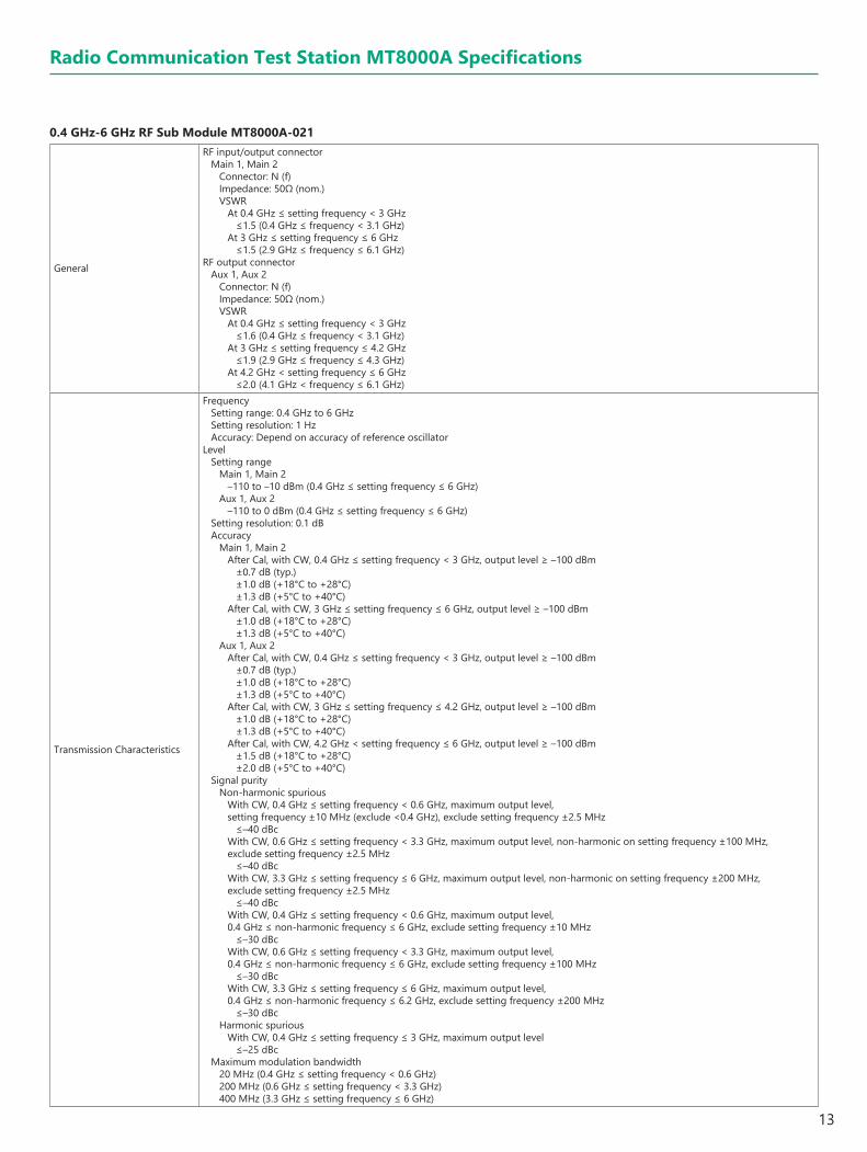
0.4 GHz-6 GHz RF Sub Module MT8000A-021
General
RF input/output connectorMain 1, Main 2
Connector: N (f)Impedance: 50Ω (nom.)VSWR
At 0.4 GHz ≤ setting frequency < 3 GHz≤1.5 (0.4 GHz ≤ frequency < 3.1 GHz)
At 3 GHz ≤ setting frequency ≤ 6 GHz≤1.5 (2.9 GHz ≤ frequency ≤ 6.1 GHz)
RF output connectorAux 1, Aux 2
Connector: N (f)Impedance: 50Ω (nom.)VSWR
At 0.4 GHz ≤ setting frequency < 3 GHz≤1.6 (0.4 GHz ≤ frequency < 3.1 GHz)
At 3 GHz ≤ setting frequency ≤ 4.2 GHz≤1.9 (2.9 GHz ≤ frequency ≤ 4.3 GHz)
At 4.2 GHz < setting frequency ≤ 6 GHz≤2.0 (4.1 GHz < frequency ≤ 6.1 GHz)
Transmission Characteristics
FrequencySetting range: 0.4 GHz to 6 GHzSetting resolution: 1 HzAccuracy: Depend on accuracy of reference oscillator
LevelSetting range
Main 1, Main 2–110 to –10 dBm (0.4 GHz ≤ setting frequency ≤ 6 GHz)
Aux 1, Aux 2–110 to 0 dBm (0.4 GHz ≤ setting frequency ≤ 6 GHz)
Setting resolution: 0.1 dBAccuracy
Main 1, Main 2After Cal, with CW, 0.4 GHz ≤ setting frequency < 3 GHz, output level ≥ –100 dBm
±0.7 dB (typ.)±1.0 dB (+18°C to +28°C)±1.3 dB (+5°C to +40°C)
After Cal, with CW, 3 GHz ≤ setting frequency ≤ 6 GHz, output level ≥ –100 dBm±1.0 dB (+18°C to +28°C)±1.3 dB (+5°C to +40°C)
Aux 1, Aux 2After Cal, with CW, 0.4 GHz ≤ setting frequency < 3 GHz, output level ≥ –100 dBm
±0.7 dB (typ.)±1.0 dB (+18°C to +28°C)±1.3 dB (+5°C to +40°C)
After Cal, with CW, 3 GHz ≤ setting frequency ≤ 4.2 GHz, output level ≥ –100 dBm±1.0 dB (+18°C to +28°C)±1.3 dB (+5°C to +40°C)
After Cal, with CW, 4.2 GHz < setting frequency ≤ 6 GHz, output level ≥ –100 dBm±1.5 dB (+18°C to +28°C)±2.0 dB (+5°C to +40°C)
Signal purityNon-harmonic spurious
With CW, 0.4 GHz ≤ setting frequency < 0.6 GHz, maximum output level,setting frequency ±10 MHz (exclude <0.4 GHz), exclude setting frequency ±2.5 MHz
≤–40 dBcWith CW, 0.6 GHz ≤ setting frequency < 3.3 GHz, maximum output level, non-harmonic on setting frequency ±100 MHz,exclude setting frequency ±2.5 MHz
≤–40 dBcWith CW, 3.3 GHz ≤ setting frequency ≤ 6 GHz, maximum output level, non-harmonic on setting frequency ±200 MHz,exclude setting frequency ±2.5 MHz
≤–40 dBcWith CW, 0.4 GHz ≤ setting frequency < 0.6 GHz, maximum output level,0.4 GHz ≤ non-harmonic frequency ≤ 6 GHz, exclude setting frequency ±10 MHz
≤–30 dBcWith CW, 0.6 GHz ≤ setting frequency < 3.3 GHz, maximum output level,0.4 GHz ≤ non-harmonic frequency ≤ 6 GHz, exclude setting frequency ±100 MHz
≤–30 dBcWith CW, 3.3 GHz ≤ setting frequency ≤ 6 GHz, maximum output level,0.4 GHz ≤ non-harmonic frequency ≤ 6.2 GHz, exclude setting frequency ±200 MHz
≤–30 dBcHarmonic spurious
With CW, 0.4 GHz ≤ setting frequency ≤ 3 GHz, maximum output level≤–25 dBc
Maximum modulation bandwidth20 MHz (0.4 GHz ≤ setting frequency < 0.6 GHz)200 MHz (0.6 GHz ≤ setting frequency < 3.3 GHz)400 MHz (3.3 GHz ≤ setting frequency ≤ 6 GHz)

14
Radio Communication Test Station MT8000A Specifications
Receiving Characteristics
FrequencySetting range: 0.4 GHz to 6 GHzSetting resolution: 1 Hz
LevelMaximum input level: +30 dBm, 0 VDC (0.4 GHz ≤ setting frequency ≤ 6 GHz, with CW)Setting range: –50 to +26 dBmSetting resolution: 0.1 dB
AmplitudeMeasurement resolution: 0.01 dBMeasurement accuracy
After Cal, with CW, 0.4 GHz ≤ setting frequency < 3 GHz, measurement bandwidth is 100 MHz, at the signal equal tothe setting frequency and the setting level
±0.5 dB (Setting level ≥ –20 dBm, typical)±0.7 dB (Setting level ≥ –40 dBm, typical)±1.0 dB (Setting level ≥ –40 dBm, +18°C to +28°C)±1.3 dB (Setting level ≥ –50 dBm, +18°C to +28°C)
After Cal, with CW, 3 GHz ≤ setting frequency ≤ 6 GHz, measurement bandwidth is 100 MHz, at the signal equal tothe setting frequency and the setting level
±1.0 dB (Setting level ≥ –40 dBm, +18°C to +28°C)±1.3 dB (Setting level ≥ –50 dBm, +18°C to +28°C)

15
Radio Communication Test Station MT8000A Specifications
Peripherals
Multiband RF Converter MA80003A
RF Input/Output Connector
Port 1, Port 2Connector: V (m)Impedance: 50Ω (nom.)VSWR: ≤2.5 (22.65 GHz ≤ frequency ≤ 31.1 GHz)
≤2.9 (35.4 GHz ≤ frequency ≤ 43.5 GHz) ≤2.9 (43.5 GHz < frequency ≤ 45.1 GHz, typ.)
Transmission Characteristics
FrequencySetting range: 24.25 GHz to 29.5 GHz, 37.0 GHz to 43.5 GHz Setting resolution: 1 HzAccuracy: Depend on accuracy of MT8000A reference oscillator
LevelSetting range: –70 to +15 dBmSetting resolution: 0.1 dBAccuracy: After Cal, with CW, Setting level ≤ ±10 dBm
±1.5 dB (24.25 GHz ≤ setting frequency ≤ 29.5 GHz, +18°C to +28°C) ±1.5 dB (37.0 GHz ≤ setting frequency ≤ 40.0 GHz, typ.) ±2.0 dB (37.0 GHz ≤ setting frequency ≤ 40.0 GHz, +18°C to +28°C) ±1.5 dB (40.0 GHz < setting frequency ≤ 43.5 GHz, typ.) ±2.0 dB (40.0 GHz < setting frequency ≤ 43.5 GHz, +18°C to +28°C)
Signal purityNon-harmonic spurious: With CW, Setting level=+10 dBm
In-band Specification:≤–40 dBc ( non-harmonic on setting frequency ±500 MHz, exclude setting frequency ±50 MHz and non-harmonic frequency < 24.25
GHz, 29.5 GHz < non-harmonic frequency < 37.0 GHz and non-harmonic frequency > 43.5 GHz)Specification for interference signal source:
≤–37 dBc ( non-harmonic on setting frequency ±1.5 GHz, exclude setting frequency ±500 MHz and non-harmonic frequency < 24.25 GHz, 29.5 GHz < non-harmonic frequency < 37.0 GHz and non-harmonic frequency > 43.5 GHz)
Out-of-band Specification:≤–30 dBc ( 24.25 GHz ≤ setting frequency ≤ 29.5 GHz, 24.25 GHz ≤ non-harmonic frequency ≤ 29.5 GHz and 37.0 GHz ≤
non-harmonic frequency ≤ 43.5 GHz, exclude setting frequency ±1.5 GHz, setting frequency - 4.5 GHz ±10 MHz and setting frequency + 4.5 GHz ±10 MHz)
≤–30 dBc ( 37.0 GHz ≤ setting frequency ≤ 43.5 GHz, 24.25 GHz ≤ non-harmonic frequency ≤ 29.5 GHz and 37.0 GHz ≤ non-harmonic frequency ≤ 43.5 GHz, exclude setting frequency ±1.5 GHz)
Maximum modulation bandwidth: 1 GHz
Receiving Characteristics
FrequencySetting range: 24.25 GHz to 29.5 GHz, 37.0 GHz to 43.5 GHz Setting resolution: 1 Hz
LevelMaximum input level: +20 dBm, 0 VDC (with CW)Setting range: –70 to +10 dBmSetting resolution: 0.1 dB
AmplitudeMeasurement resolution: 0.01 dBMeasurement accuracy: After Cal, with CW, measurement bandwidth 100 MHz, at the signal equal to the setting frequency and the
setting level24.25 GHz ≤ setting frequency ≤ 29.5 GHz
±1.0 dB (–50 dBm ≤ setting level ≤ +10 dBm, typ.)±2.0 dB (–70 dBm ≤ setting level < –50 dBm, typ.)±1.5 dB (–50 dBm ≤ setting level ≤ +10 dBm, +18°C to +28°C)±2.5 dB (–70 dBm ≤ setting level < –50 dBm, +18°C to +28°C)
37.0 GHz ≤ setting frequency ≤ 40.0 GHz±1.5 dB (–50 dBm ≤ setting level ≤ +10 dBm, typ.)±2.0 dB (–70 dBm ≤ setting level < –50 dBm, typ.)±2.0 dB (–50 dBm ≤ setting level ≤ +10 dBm, +18°C to +28°C)±2.5 dB (–70 dBm ≤ setting level < –50 dBm, +18°C to +28°C)
40.0 GHz ≤ setting frequency ≤ 43.5 GHz±1.5 dB (–50 dBm ≤ setting level ≤ +10 dBm, typ.)±2.0 dB (–65 dBm ≤ setting level < –50 dBm, typ.)±2.0 dB (–50 dBm ≤ setting level ≤ +10 dBm, +18°C to +28°C)±2.5 dB (–65 dBm ≤ setting level < –50 dBm, +18°C to +28°C)
IF Input/Output Connector Connector: N (f)Impedance: 50Ω (nom.)
External Control Connector Round multiway type connector
DC Input Connector Voltage: 18 VDCCurrent: ≤5.5 A
Dimensions and Mass Dimensions: 83 (W) × 175 (H) × 304 (D) mm (excluding projections)Mass: ≤6 kg
Environmental Conditions Operating temperature range: +5°C to +45°C (without condensation)Storage temperature range: –20°C to +71°C (without condensation)
CEEMC 2014/30/EU, EN61326-1, EN61000-3-2LVD 2014/35/EU, EN61010-1RoHS 2011/65/EU, (EU) 2015/863, EN IEC 63000: 2018

16
Base Station Test Suite for NR mmWave MX800045AError Vector Magnitude (EVM)• Test SignalSignal Analyzer:
NR-FR2-TM3.1, 120 kHz Subcarrier Spacing (64QAM), Input Level: –10 dBm
Signal Generator: Uplink, CP-OFDM, 120 kHz Subcarrier Spacing (64QAM), Output Level: –10 dBm
FrequencyChannel
BandwidthEVM (rms) (meas.)
Signal Analyzer Signal Generator
28 GHz
100 MHz 1.56% 1.14%
200 MHz 1.63% 1.27%
400 MHz 1.73% 1.48%
39 GHz
100 MHz 2.04% 1.92%
200 MHz 1.99% 2.16%
400 MHz 2.08% 2.53%
Adjacent Channel Leakage Ratio (ACLR)• Test SignalSignal Analyzer:
NR-FR2-TM1.1, 120 kHz Subcarrier Spacing (QPSK), Input Level: –10 dBm
Signal Generator: Uplink, CP-OFDM, 120 kHz Subcarrier Spacing (QPSK), Output Level: –10 dBm
FrequencyChannel
BandwidthACLR (meas.)
Signal Analyzer Signal Generator
28 GHz
100 MHz –47.17 dBc –47.9 dBc
200 MHz –41.32 dBc –45.44 dBc
400 MHz –40.14 dBc –41.12 dBc
39 GHz
100 MHz –47.04 dBc –47.3 dBc
200 MHz –41.58 dBc –44.8 dBc
400 MHz –40.77 dBc –41.4 dBc
Base Station Test Suite for NR sub-6GHz MX800046AError Vector Magnitude (EVM)• Test SignalSignal Analyzer:
NR-FR1-TM3.1a, 30 kHz Subcarrier Spacing (256QAM), Input Level: –10 dBm
Signal Generator: Uplink, CP-OFDM, 30 kHz Subcarrier Spacing (256QAM), Output Level: –10 dBm (Main)/0 dBm (AUX)
FrequencyChannel
BandwidthEVM (rms) (%) meas.
Signal Analyzer Signal Generator
3.7 GHz 100 MHz 0.91%1.00% (Main)0.95% (AUX)
4.5 GHz 100 MHz 0.96%1.04% (Main)1.03% (AUX)
5 GHz 100 MHz 0.95%1.06% (Main)1.02% (AUX)
Adjacent Channel Leakage Ratio (ACLR)• Test SignalSignal Analyzer:
NR-FR1-TM1.1, 30 kHz Subcarrier Spacing (QPSK), Input Level: –10 dBm
Signal Generator: Uplink, CP-OFDM, 30 kHz Subcarrier Spacing (QPSK), Output Level: –10 dBm (Main)/0 dBm (AUX)
FrequencyChannel
BandwidthACLR
Signal Analyzer Signal Generator
3.7 GHz 100 MHz –50.36 dBc–46.40 dBc (Main)–47.28 dBc (AUX)
4.5 GHz 100 MHz –49.62 dBc–44.94 dBc (Main)–45.54 dBc (AUX)
5 GHz 100 MHz –49.12 dBc–45.47 dBc (Main)–45.67 dBC (AUX)
MX800045A/MX800046A Measurement Examples
The following tables show examples of EVM and ACLR measurements using the signal analyzer and signal generator with the MX800045A and MX800046A software.
Typical (typ.): Performance not warranted. Most products meet typical performance.Nominal (nom.): Values not warranted. Included to facilitate application of product.Measured (meas.): Performance not warranted. Data actually measured from randomly selected measuring instruments.

17
Radio Communication Test Station MT8000A Ordering Information
Model/Order No. Name MT8000A
Main FrameRadio Communication Test Station
J1211J1440AW3955AEMX800000A
Standard AccessoriesPower Cord (3.0 m, 100 V, 3 core) : 1 pcLAN Cable : 1 pcMT8000A Operation Manual (DVD) : 1 pcPlatform Software
MT8000A-001MT8000A-020MT8000A-021
OptionsControl ModuleRF Base Module0.4 GHz-6 GHz RF Sub Module
MA80003AJ1771AJ1771BJ1771CJ1772AJ1772BJ1772CJ1806B
ConverterMultiband RF ConverterCoaxial Cord (N-N, 1.0 m)Coaxial Cord (N-N, 3.0 m)Coaxial Cord (N-N, 5.0 m)Control Cable, 1.0 mControl Cable, 3.0 mControl Cable, 5.0 mVJ-KJ Adapter
Please specify the model/order number, name and quantity when ordering.The names listed in the chart below are Order Names. The actual name of the item may differ from the Order Name.
Model/Order No. Name J0127AJ1398AJ1440A
Application PartsCOAXIAL CORD, 1.0MN-SMA ADAPTORLAN Cable
MX800045AMX800046A
Software OptionsBase Station Test Suite for NR mmWaveBase Station Test Suite for NR sub-6GHz
MX800045A-SS101
MX800046A-SS101
Support ServicesBase Station Test for 5G NR mmWave Support Service (Per Year)Base Station Test for 5G NR sub-6GHz Support Service (Per Year)
MT8000A-ES210MT8000A-ES310MT8000A-ES510MA80003A-ES210 MA80003A-ES310MA80003A-ES510
Warranty Services2 Years Extended Warranty Service3 Years Extended Warranty Service5 Years Extended Warranty Service2 Years Extended Warranty Service3 Years Extended Warranty Service5 Years Extended Warranty Service

Anritsu Americas Sales Company450 Century Parkway, Suite 190, Allen, TX 75013 U.S.A.Phone: +1-800-Anritsu (1-800-267-4878)
• CanadaAnritsu Electronics Ltd.700 Silver Seven Road, Suite 120, Kanata, Ontario K2V 1C3, CanadaPhone: +1-613-591-2003 Fax: +1-613-591-1006
• BrazilAnritsu Eletronica Ltda.
• MexicoAnritsu Company, S.A. de C.V.Blvd Miguel de Cervantes Saavedra #169 Piso 1, Col. GranadaMexico, Ciudad de Mexico, 11520, MEXICOPhone: +52-55-4169-7104
• United KingdomAnritsu EMEA Ltd. 200 Capability Green, Luton, Bedfordshire, LU1 3LU, U.K.Phone: +44-1582-433200 Fax: +44-1582-731303
• FranceAnritsu S.A.12 avenue du Québec, Immeuble Goyave,91140 VILLEBON SUR YVETTE, FrancePhone: +33-1-60-92-15-50
• GermanyAnritsu GmbHNemetschek Haus, Konrad-Zuse-Platz 1, 81829 München, Germany Phone: +49-89-442308-0Fax: +49-89-442308-55
• ItalyAnritsu S.r.l.Spaces Eur Arte, Viale dell’Arte 25, 00144 Roma, ItalyPhone: +39-6-509-9711
• SwedenAnritsu ABKistagången 20 B, 2 tr, 164 40 Kista, SwedenPhone: +46-8-534-707-00
• FinlandAnritsu ABTechnopolis Aviapolis, Teknobulevardi 3-5 (D208.5.),FI-01530 Vantaa, FinlandPhone: +358-20-741-8100
• DenmarkAnritsu A/Sc/o Regus Winghouse, Ørestads Boulevard 73, 4th floor, 2300 Copenhagen S, DenmarkPhone: +45-7211-2200
• RussiaAnritsu EMEA Ltd.Representation Office in RussiaTverskaya str. 16/2, bld. 1, 7th floor., Moscow, 125009, RussiaPhone: +7-495-363-1694Fax: +7-495-935-8962
• SpainAnritsu EMEA Ltd.Representation Office in SpainPaseo de la Castellana, 141. Planta 5, Edificio Cuzco IV28046, Madrid, SpainPhone: +34-91-572-6761
• AustriaAnritsu EMEA GmbHAm Belvedere 10, A-1100 Vienna, AustriaPhone: +43-(0)1-717-28-710
• United Arab EmiratesAnritsu EMEA Ltd.Anritsu A/S
2106
• SingaporeAnritsu Pte. Ltd.11 Chang Charn Road, #04-01, Shriro House, Singapore 159640Phone: +65-6282-2400Fax: +65-6282-2533
• VietnamAnritsu Company Limited16th Floor, Peakview Tower, 36 Hoang Cau Street, O Cho Dua Ward, Dong Da District, Hanoi, VietnamPhone: +84-24-3201-2730
• IndiaAnritsu India Private Limited6th Floor, Indiqube ETA, No.38/4, Adjacent to EMC2,Doddanekundi, Outer Ring Road, Bengaluru – 560048, IndiaPhone: +91-80-6728-1300Fax: +91-80-6728-1301
Specifications are subject to change without notice.
• United States
• P.R. China (Shanghai)Anritsu (China) Co., Ltd.Room 2701-2705, Tower A, New Caohejing International Business Center No. 391 Gui Ping Road Shanghai, 200233, P.R. ChinaPhone: +86-21-6237-0898Fax: +86-21-6237-0899
• P.R. China (Hong Kong)Anritsu Company Ltd.Unit 1006-7, 10/F., Greenfield Tower, Concordia Plaza,No. 1 Science Museum Road, Tsim Sha Tsui East, Kowloon, Hong Kong, P.R. ChinaPhone: +852-2301-4980Fax: +852-2301-3545
• JapanAnritsu Corporation8-5, Tamura-cho, Atsugi-shi, Kanagawa, 243-0016 JapanPhone: +81-46-296-6509Fax: +81-46-225-8352
• KoreaAnritsu Corporation, Ltd.5FL, 235 Pangyoyeok-ro, Bundang-gu, Seongnam-si, Gyeonggi-do, 13494 KoreaPhone: +82-31-696-7750Fax: +82-31-696-7751
• AustraliaAnritsu Pty. Ltd.
• TaiwanAnritsu Company Inc.7F, No. 316, Sec. 1, NeiHu Rd., Taipei 114, TaiwanPhone: +886-2-8751-1816Fax: +886-2-8751-1817
Unit 20, 21-35 Ricketts Road, Mount Waverley, Victoria 3149, AustraliaPhone: +61-3-9558-8177Fax: +61-3-9558-8255
Office No. 164, Building 17, Dubai Internet CityP. O. Box – 501901, Dubai, United Arab EmiratesPhone: +971-4-3758479
Praça Amadeu Amaral, 27 - 1 Andar01327-010 - Bela Vista - Sao Paulo - SP, BrazilPhone: +55-11-3283-2511Fax: +55-11-3288-6940
Printed in Japan 29/SEP/2021 ddcm/CDT Catalog No. MT8000A_BTS_Solution-E-A-1-(1.00)