Potential base for Radio Signals Items Specifications : Jusslandian List of Radio Signals

Base Radio User Manual
Rev 1.56 June 2004
______________________________________________________________________________________________________________________________________ A Division of Adaptive Instruments Corp. 577 Main Street · Hudson, MA 01749 U.S.A. TEL: 800-879-6576 · 978-568-0500 FAX: 978-568-9085 Email: [email protected] www.accutechinstruments.com


Rev 1.56 I
User Manual
Base Radio Models WI-BR-I-XP, WI-BR-I-XP-MOD and WI-BR-I-XP-AO Versions 1.56 or later
© Adaptive Instruments Corp., 2005.
Printed in the USA
Important Information to the User !
• Changes or modifications not expressly approved by Adaptive Instruments, LLC may void the user’s authority to operate the equipment.
• This device complies with Part 15 of the FCC Rules. Operation is subject to the
following two conditions: 1) this device may not cause harmful interference, and 2) this device must accept any interference received, including interference that may cause undesired operation.
• This device is for mobile and fixed use only (not portable or body-worn). A
separation distance of 20cm must be maintained at all times between the antenna and the body of the user and bodies of nearby persons.
• If the Wireless Instrumentation Manager (RF Server) software is shutdown, the
RS-485 network MUST be physically disconnected from the PC as the serial port is no longer being controlled by the software and may disrupt communica-tions between the Base Radio(s) and Analog/Digital Output Module(s).
• This device has been designed to operate with an antenna having a maximum
gain of 9 dBd. Antenna having a higher gain is strictly prohibited per regulations of Industry Canada. The required antenna impedance is 50 ohms.
• To reduce potential radio interference to other users, the antenna type and its gain
should be so chosen that the equivalent isotropically radiated power (EIRP) is not more than that required for successful communication.
• The installer of this radio equipment must ensure that the antenna is located or
pointed such that it does not emit RF field in excess of Health Canada limits for the general population; consult Safety Code 6, obtainable from Health Canada’s website www.hc-sc.gc.ca/rpb.
!
FCC Certification • This product is a frequency hopping RF transceiver module for the 900MHz ISM
band, designed to meet FCC 15.247, and is used in industrial control and moni-toring applications.
• The antenna is factory installed and MUST NOT be removed or modified by
user.
! !
NOTE • This document cannot be changed without prior FM approval.
Accutech A Division of Adaptive Instruments Corp. 577 Main Street · Hudson, MA 01749 USA TEL: 800-879-6576 · 978-568-0500 FAX: 978-568-9085 Email: [email protected] Web: www.accutechinstruments.com


Rev 1.56 III
Table of Contents
Section 1: Introduction ____________________________________ 1 1.1: Using This Manual 1 1.2: About the Device 2 1.3: Unpacking 2 1.4: Software Compatibility 2
Section 2: In a Hurry? ____________________________________ 3 Section 3: Installation _____________________________________ 4
3.1: Mechanical Installation 4 3.1.1: Base Radio Positioning 4 3.1.2: Base Radio Mounting 5
3.2: Electrical Installation 5 3.2.1: Electrical Specifications 5 3.2.2: Wiring Power to the Base Radio 6 3.2.3: Wiring RS-485 to the Base Radio 6 3.2.4: Wiring an RS-232 Converter to the Base Radio 6 3.2.5: Wiring the Analog Output Loop 7 3.2.6: Terminating the Base Radio 7 3.2.7: Grounding the Base Radio 7
Section 4: General Configuration ___________________________ 8 4.1: Base Radio Displayed Messages 8
4.1.1: The Read Only Sequence 8 4.2: Overall Configuration Menu Map 9 4.3: The Number of Wireless Instruments Setting (NUM WI) 9 4.4: Setting the User Password 9
Section 5: Configuring the RF Communications ______________ 10 5.1: RF Channel Selection 10 5.2: RF Baud Rate Selection 10
Section 6: Configuring the Modbus Communications__________ 11 6.1: Base Radio Setup 11
6.1.1: Modbus Baud Rate Setting 11 6.1.2: Modbus Device ID 12 6.1.3: Modbus Parity 13 6.1.4: Modbus Mapping Mode 13
6.2: Modbus Communication Protocol 14 6.3: Modbus Commands 15
6.3.1: Command 03-Read Holding Registers 15 6.3.2: Command 08-Diagnostic 18 6.3.3: Command 11-Get Com Event Counter 18 6.3.4: Command 12-Get Com Event Log 19 6.3.5: Command 17-Report Slave ID 19 6.3.6: Command 43-Read Device ID 19
Section 7: Configuring the Analog Output Loop ______________ 20 7.1: Trimming the Output Loop 20 7.2: Selecting the Failsafe Output 21 7.3: Selecting Which Field Unit is Output 21
Section 8: Technical Specifications _________________________ 22 Appendix A: Navigating the Menus_________________________ 23 Appendix B: Base Radio Menu Map________________________ 24

Accutech Wireless Base Radio User Manual
IV Rev 1.56
3.1: General Layout .................................................................................................. 4 3.2: Overall Wiring Schematic ................................................................................. 5 3.3: Terminal Block Labels ...................................................................................... 5 3.4: Wiring Power to the Base Radio ....................................................................... 6 3.5: Wiring RS-485 to the Base Radio ..................................................................... 6 3.6: Base Radio to RS-232 Converter Wiring Diagram........................................... 6 3.7: Wiring the 4-20mA Loop to the Base Radio..................................................... 7 3.8: Example of End Unit in Daisy-Chain Configuration ........................................ 7 3.9: Example of Correct Termination Resistor Setup .............................................. 7 4.1: Base Radio Power-UP and Operations Sequence ............................................. 8 4.2: The Read Only Sequence .................................................................................. 8 4.3: Overall Configuration Menu Map..................................................................... 9 4.4: Menu Map to Number of Wireless Instruments Setting.................................... 9 4.5: Menu Map to Password Setting......................................................................... 9 5.1: Menu Map to RF Channel Setting................................................................... 10 5.2: Menu Map to Baud Rate Setting ..................................................................... 10 6.1: Menu Map to Modbus Baud Rate Setting ....................................................... 11 6.2: Menu Map to Modbus Device ID Setting ....................................................... 12 6.3: Menu Map to Modbus Parity Setting .............................................................. 13 6.4: Menu Map to Modbus Mapping Mode Setting .............................................. 13 7.1: Menu Map to Trim Function ........................................................................... 20 7.2: Menu Map to Failsafe Output Setting ............................................................. 21 7.3: Menu Map to Field Unit Output Option.......................................................... 21 8.1: Overall Base Radio Dimensions...................................................................... 22
Table of Figures

Rev 1.56 1
Introduction
Section 1
1.1: USING THIS MANUAL This manual is designed to assist in installing, operating, and maintaining Accutech Model WI-BR-I-XP, WI-BR-I-XP-MOD and WI-BR-I-XP-AO Base Radios. The manual is broken into sections as follows: Section 2: In a Hurry? This section summarizes what must be done in order to get the device in-stalled, configured and in operation quickly. However, it does not provide detailed or how-to information to perform the tasks outlined. Section 3: Installation This section explains how to correctly wire power, communications, ana-log output loops and mechanical installation considerations. Also covered in this section is how to “daisy-chain” multiple devices together on the same power and communications supplies (Modbus Base Radio Only). Proper communications termination is also covered. Section 4: General Configuration In this section general configuration options such as password protecting, and selecting a user password are discussed. Also covered, is the impor-tance of the Number of Wireless Instruments (NUM WI) setting, as well as how to configure this setting. Section 5: Configuring the RF Communications This section covers the setup of the Base Radio RF Communications which allow the Base Radio to detect and achieve communication with Field Units that have been placed in service. Section 6: Configuring the MODBUS Communications This section only applies if you have purchased the Modbus Base Radio (WI-BR-I-XP-MOD). This section covers the various Base Radio settings that must be config-ured for Modbus communication such as baud rate, parity, device ID’s, and register mapping modes. Also covered in this section is a brief discus-sion of the Modbus communications protocol and Modbus commands that are used with this device. Modbus register locations are also discussed within this section. Section 7: Configuring the Analog Output Loop This section only applies if you have purchased the Analog Output Base Radio (WI-BR-I-XP-AO). Items such as trimming the output loop, selecting the failsafe output, and selecting the field unit to be output are discussed in this section. Section 8: Technical Specifications This section explains the technical specifications that are associated with this device, such as power characteristics, accuracy, and operating charac-teristics.

Accutech Wireless Base Radio User Manual
2 Rev 1.56
1.2: ABOUT THE DEVICE The Accutech Base Radio is a reliable Radio Frequency (RF) transceiver with a variety of available outputs, contained in an explosion proof hous-ing useable in many hazardous and hard-to-reach areas. The time and ex-pense of running wires often makes it difficult to measure parameters that have an economic impact on your plant operation, but the Base Radio al-lows you to quickly and accurately monitor those devices at fraction of the cost, giving you bigger and faster returns on your instrumentation invest-ments. The Base Radio communicates in a secure, digital protocol over a band of frequencies from 902MHz to 928MHz. These devices require no wires, permits or licenses, and are easily setup and installed right out of the box. The Accutech Base Radio may be used to communicate with many Field Units in various applications. You can use this device for long-term moni-toring in remote locations, for short-term data gathering on process condi-tions, or to quickly test the economic viability of a new installation. The purpose of this Guide is to help you install and maintain your Ac-cutech Base Radio.
1.3: UNPACKING Remove the Packing List and check off the actual equipment received. If you have any questions on your shipment, please call your Accutech Rep-resentative. Upon receipt of shipment, inspect the container for any signs of damage in transit. Especially take note of any evidence of rough han-dling. Report any apparent damage immediately to the shipping agent. Please note that sometimes units are assembled with accessories when shipped. Inspect the shipment carefully if you think that something is missing. This is rare, as we take considerable care to pack units for ship-ment, but it does sometimes happen. Please give us a call and we may be able to resolve this matter quickly over the phone.
NOTE Please note that the carrier will not honor any claims for damage unless all shipping materials are saved for their examination. If damage is found during examining and removal of the contents, save the packing material and the carton.
1.4: SOFTWARE COMPATABILITY
Software for Accutech is revised periodically. Internal device software may contain portions that are not compatible with previous versions of the Wireless Instrumentation Manager software. To ensure software compatibility, Wireless Instrumentation Manager soft-ware version 1.56.126 or later must be used. If you believe you are experi-encing software compatibility issues please call Accutech Customer Ser-vice at (978) 568-0500 or email [email protected].

Rev 1.56 3
This section summarizes what must be done in order to get the device in-stalled, configured and in operation quickly. However, it does not provide detailed or how-to information to perform the tasks outlined.
In a Hurry?
Section 2
1. Wire 24VDC power to the Base Radio (See Diagram below) 2. Wire WIM RS-485 communications to the left-most terminal of Base
Radio (See side Diagram) 3. Wire Modbus RS-485 communications to the center terminal of the
Base Radio (WI-BR-I-XP-MOD only) (See Diagram below) 4. Place terminating resistor in terminal only if Base Radio will be used
as an End Unit (See side Diagram) 5. Wire the Analog Output Loop (WI-BR-I-XP-AO only) (See Diagram)
6. The Base Radio RF Settings should be configured as follows:
• RF Channel to any available RF CHAN that matches the one used by Field Units you with which wish to communicate (other than RF OFF)
• Baud Rate to 76.8K or the Baud Rate used by Field Units with which you wish to communicate
• Number of WI’s = to the number of Field Units to communi-cate with this Base Radio.
7. Configure the Modbus settings (WI-BR-I-XP-MOD only) 8. Configure the Analog Output Loop settings (WI-BR-I-XP-AO only) 9. Verify “COMM OK” message on Base Radio LCD screen
If you are not receiving a “COMM OK” message on the Base Radio check the following: • Is the Base Radio set to the above
listed configurations? • Are all the Field Units on? • Are the Field Units set to the match-
ing configurations? (See Section 5 of Field Unit and Base Radio User Manuals)
• Are the Base Radio and Field Units unable to communicate due to ob-structions or distance? (See Field Unit Manual: Field Unit Placement section)
• Did you perform the Simple RF Placement Procedure? (See Field Unit Guide: A Simple RF Placement
Caution If the Base Radio is not energized for more than 30 minutes, the Field Units should also be turned off to preserve battery life. Leaving the Field Units on when the Base Radio is not energized or out of range will cause the Field Units to transmit very frequently and drastically reduces their bat-tery life.
! !

Accutech Wireless Base Radio User Manual
4 Rev 1.56
Installation
Section 3
3.1: Mechanical Installation In this section mechanical installation instructions are discussed for the various setup capabilities of the Analog/Digital Output Module. The sub-sections are as follows:
3.1.1: Base Radio Positioning 3.1.2: Base Radio Mounting
Warning During installation do not apply force to the in-strument housing or antenna. Use a proper wrench for all installations. Failure to use correct installa-tion procedures can cause damage to the Base Radio.
! !
The Accutech Base Radio is a rugged device, but it will give much better service if installed with careful consideration as noted in this manual. It may be utilized in any service so long as care is exercised to prevent ex-posing the sensing elements to excess stress or temperature. Installation practices have a lot to do with these service parameters and the life that you can expect from your Accutech Base Radio. The main considerations for installation are covered below. Give careful consideration to the environment where you will be installing your instrument. Avoid installations that expose the device to excess tem-perature, high vibration, considerable shock, or exposure to dripping con-densate or corrosive materials. Also avoid installing the device in an un-serviceable location. Most often these problems can be avoided with some thought at the time of installation. The practices noted below are generally recommended, but they can only act as a guideline and cannot cover all possible variations. The final installation must be made at the discretion and approval of the user. You must be the judge of the actual installation.
3.1.1: Base Radio Positioning Correct positioning of the Base Radio will ensure the best performance of the device. Because the Base Radio is the central communication device of all Field Units that are assigned to it. The Base Radio should be located in an area that is somewhat central to all the Field Units. Figure 3.1 is a picture of a general Base Radio layout. The maximum dis-tance is determined by a number of factors, including the Baud Rate Set-ting. When planning the positioning of the Base Radio try to place the Base Radio in an elevated position to avoid human traffic interference. Remember, the approximate line of sight range between a Field Unit and Base Radio is determined by the Baud Rate as listed below:
• 76.8K -76.8 Kbaud, Range of 500 to 750ft • 19.2K - 19.2 Kbaud, Range of 2,000 to 2500ft • 4.8K - 4.8 Kbaud, Range of 3,000ft
Note: This range is reduced by the amount of RF Noise present, obstruc-tions, and the material properties of those obstructions. Only place the Base Radio in ambient operating temperatures of -40°F to 185°F (-40°C to 85°C). Make sure you have power and communication to the Base Radio avail-able. (See Electrical Installation section) Because there are so many setup possibilities we cannot cover them all. A correct setup would make sure that the above warnings are heeded, and that the Field Unit and Base Radio are capable of communication. The RF Placement Procedure section of the Field Unit Guide will help you to de-termine if you have a selected the correct installation points and orienta-tions for your application.
Figure 3.1: General Layout

Rev 1.56 5
3.2: Electrical Installation In this section wiring instructions are discussed for the various setup capa-bilities of the Base Radio. The subsections are as follows:
3.2.1: Electrical Specifications 3.2.2: Wiring Power to the Base Radio 3.2.3: Wiring RS-485 to the Base Radio 3.2.4: Wiring an RS-232 Converter to the Base Radio 3.2.5: Wiring the Analog Output Loop 3.2.6: Terminating the Base Radio 3.2.7: Grounding the Base Radio Housing
Warning Remember to turn off all power BEFORE hook-ing up any wires!
! !
3.2.1: Electrical Specifications • 24VDC Power Supply with 0.5 Amp minimum output Recommend 22AWG Power Supply wire • 2 Wire RS-485 Serial Communications Cable Recommend Belden 3105A shielded and protected 22AWG or equivalent • 120 W, ± 5%, ¼ W resistor for RS-485 termination • RS-485 to RS 232 converter B&B model 485LDRC9 or equivalent • 8 AWG bare or green covered grounding cable for housing ground
In Figure 3.2, an overall wiring schematic is shown. Note that the ground-ing screw is located on the outside of the Base Radio housing.
Figure 3.2: Overall Wiring Schematic
Explosions may result in death or serious injury. Do not remove the instrument cover in explosive atmospheres when power and communications are on.
Warning ! !
To begin the electrical installation first remove the explosion proof hous-ing cover from the Base Radio, if you have not already done so. Point the Base Radio antenna away from you and look at the green PC Board found directly underneath the NEXT and ENTER buttons. You should see two terminal blocks and some labels as shown in Figure 3.3. Once you have located these terminal blocks you can wire the Base Radio accordingly. The best way to wire the Base Radio is to:
• Remove both terminal blocks from the jacks on the Base Radio
• Insert the wire through the conduit hole on the bottom right of the Base Radio
• Secure the wire into the proper terminal blocks • Then plug the terminal blocks back into the proper jacks on
the Base Radio.
Figure 3.3: Terminal Block Labels
Caution If the Base Radio is not energized for more than 30 minutes, the Field Units should also be turned off to preserve battery life. Leaving the Field Units on when the Base Radio is not energized or out of range will cause the Field Units to transmit very frequently and drastically reduces their bat-tery life.
! !

Accutech Wireless Base Radio User Manual
6 Rev 1.56
Caution Make sure only ONE power supply is routed to the Base Radio at any time!
(Does not apply to Loop Power Supplies)
! !
The Accutech Base Radio is designed to use a 24 VDC power supply at a minimum of 0.5 Amps. Accutech offers 110VAC/120VAC-15W DIN rail mounted 24VDC converter for this purpose. For more information contact your Accutech Representative. The Ground or Negative wire should be placed in the left most slot labeled “GND” on the PCBoard of the terminal block in Figure 3.4. The Positive wire should be placed in the same terminal block in the slot labeled “24V” on the PCBoard as shown in Figure 3.4.
3.2.2: Wiring Power to the Base Radio
Figure 3.4: Wiring Power to the Base Radio
3.2.3: Wiring RS-485 to the Base Radio
The Base Radio also requires a 2 wire RS-485 cable to be wired for com-munications. Wiring communications to a PC in order to run the Wireless Instrumentation Manager (WIM) software requires the use of an RS-485 to RS-232 converter as most PC’s cannot be wired directly to RS-485. To wire the RS-485 cable to the Base Radio we recommend using a 22AWG twisted pair shielded wire. Place one of the twisted pair wires in the “A” (Tx+/Rx+) slot of the same terminal block as the power supply wires, and the other wire in the “B” (Tx-/RX-) slot of the terminal block as shown below in Figure 3.5.
Figure 3.5: Wiring RS-485 to the Base Radio
NOTE The RS-485 communication setup is half duplex. If the Base Radio in the application is wired to an RS-485 to RS-232 converter, the A (Tx+/Rx+) and B (Tx-/Rx-) wires may need to be crossed for correct operation. Please see the converter’s user manual for further instructions.
Accutech offers an optically isolated, surge protected, DIN Rail mount-able B&B Electronics converter (Model 485LDRC9). Because there are many RS-485/232 Converters available, please see your converters in-struction manual for details as this section will only discuss the wiring of the 485LDRC9 converter. The Base Radio communicated via a half-duplex differential signal with A being Tx+/Rx+ and B being Tx-/Rx-. To properly wire the Base Radio to the 485LDRC9, you should follow Figure 3.6. To configure the 485LDRC9 to the appropriate baud rate (38.4Kbaud), as set of dip switches must be configured. These switches can be found on the side of the converter. The first four switches should be in the ON posi-tion to indicate that the communications are half duplex. The fifth switch should also be in the ON position as this activates the termination resistor within the converter. Finally, switches six, seven, and eight should be set to the OFF position to indicate the correct baud rate. (Note: An 8.2K resis-tor (R11) has been installed at the factory to achieve these higher baud rates. If you did not purchase the converter from the factory you will need to install this resistor). To wire power to the 485LDRC9, place a +10 to 30 VDC supply to termi-nal F, and place the ground (V-) to terminal C. The final step in installing the converter is to attach an RS-232 (serial) cable from the converter to an available serial port on your computer.
Figure 3.6: Base Radio to RS-232 Converter Wiring Diagram
3.2.4: Wiring an RS-232 Con-verter to the Base Radio

Rev 1.56 7
This section only applies if you have purchased the Analog Output option. If you have purchased the Analog Output option for your Base Radio, then the Base Radio is able to output a 4-20mA signal loop via the “Loop” Ter-minal on the Base Radio.
To wire the analog output loop, an external loop power supply must be supplied. An example is shown in Figure 3.7.
Section 3: Installation
Figure 3.7: Wiring the 4-20mA Loop to the Base Radio
3.2.5: Wiring the Analog Output Loop (WI-BR-XP-AO only)
NOTE The Base Radio Analog Output is only capable of a 4-20mA loop. Do not wire the Base Radio to a 0-10V or 0-5V loop as this may cause irreparable damage to the Base Radio.
3.2.6: Terminating the Base Radio RS-485 is capable of maintaining communications over a maximum dis-tance of 4000 feet. In most (and we recommend all) situations the unit that comprises an “end” of an RS-485 network should be terminated by a resis-tor wired across the A and B wires. In the case of a daisy-chained application the end unit should be termi-nated. The end unit is the unit that is located at the end of series of units. In a PC to Base Radio only application, the end unit is the Base Radio. Note: a PC is also an end unit, but the termination for this end unit is done within the converter. In a multiple unit daisy-chain application the end unit is shown in Figure 3.8. Termination of an end unit is done by placing a resistor across the A and B wires of the RS-485 cable. The value of this resistor should match the characteristic impedance (Zo) of the RS-485 cable. The characteristic im-pedance (Zo) is published by the manufacturer of the RS-485 cable you are using. If you are using the Belden RS-485 wire recommended under the Wiring RS-485 to the Base Radio section the value of the resistor should be a 120 ohm ¼ watt resistor. To terminate a Base Radio place one end of the resistor in the open termi-nal block’s B slot and place the other end of the resistor in the open termi-nal block’s A slot. Doing so will place the resistor across the A and B wires as needed. An example of this is shown below in Figure 3.9.
Figure 3.8: Example of End Unit in Daisy-Chain Configuration
Figure 3.9: Example of Correct Termi-nation Resistor Setup
3.2.7: Grounding the Base Radio In order to assure safety requirements on your Base Radio, the Base Radio housing must be grounded. We have provided a grounding screw located on the left side of the Base Radio housing. To ground the Base Radio sim-ply place a wire from the grounding screw to a grounded object. Possible grounded objects include:
• The building’s metal frame-work • Any electrical conduit • A suitable grounding or lightning rod

Accutech Wireless Base Radio User Manual
8 Rev 1.56
General Configuration
Section 4
This section discusses the generalities around configuring the Base Radio via the next and enter buttons. The subsections are as follows:
4.1: Base Radio Displayed Messages 4.1.1: The Read-Only Sequence
4.2: The Overall Configuration Menu Map 4.3: The Number of Wireless Instruments Setting 4.4: Setting a User Password
Figure 4.1: Base Radio Power-Up and Operations LCD Sequences
The Base Radio should be on if power is being supplied (See Section 3.2: Electrical Installation). Upon power-up, the Base Radio will display a Power-Up Sequence, and then go into an Operations Sequence. These Sequences are shown in Figure 4.1 below:
4.1: Base Radio Displayed Messages
NOTE During configuration and testing, keep Field Units at least one foot apart and away from the Base Radio to ensure good communications.
4.1.1: The Read Only Sequence Once the Base Radio is in the Operations Sequence, a user may access the READ-ONLY Sequence without a password by simply pressing the EN-TER button at any time. The Read-Only Sequence, as shown in Figure 4.2, displays extra information about the current settings of the Base Radio that are not seen during the Operations Sequence, but does not allow any changes to be made to these settings.
4.2: The Read Only Sequence

Rev 1.56 9
A complete Base Radio Menu Map is shown in Appendix B. Below is an overall view of the configuration menu to aid the user in setting up the Base Radio for proper operation.
Figure 4.3: Overall Configuration Menu Map
4.2: Overall Configuration Menu Map
Section 4: General Configuration
NOTE The RS-485 is only available if you have ordered to Modbus communication option (WI-BR-I-XP-MOD). TRIM, FAILSAF, & OUTPUT are only available within the menus if you have ordered the WI-BR-I-XP-AO model Base Radio, which has the Ana-log Output loop enabled.
NOTE The user must enter a four digit password to enter the CONFIG and DIAGNSE. The FACTORY menu is for factory use only. The default user password is 0000. For more information on the password see Section 4.4.
4.3: The Number of Wireless Instruments Setting
The Number of Wireless Instruments setup allows you to track Field Unit communication. By indicating the number of Field Units allotted to that particular Base Radio, the Base Radio can judge whether or not it is miss-ing communication with a Field Unit and then warn the user. For example, if you had 10 Field Units to be set to this Base Radio, you would set the number of wireless instruments to 10. When you returned to the operations sequence you would then read “BASE OK” and “10 WI” if all the Field Units were in communication with the Base Radio. If one Field Unit was not in communication with the Base Radio, you would read “MIS 1” and “9 WI” for the 1 missing Field Unit. Follow the Base Radio menu map shown to the left in Figure 4.4 to con-figure the number of wireless instruments (Field Units). The factory de-fault is 001. There is a limit of 50 Field Units per Base Radio.
Figure 4.4: Menu Map to Number of Wireless Instruments Setting
4.3: The Number of Wireless Instruments Setting
4.4: Setting the User Password Each Base Radio has a password that will lock out undesired users from making changes to the Base Radio. Any user may still view some of the Base Radio settings by pressing the ENTER key during the Operations Sequence and viewing the Read Only Sequence. The password is a four-digit password. The factory default is 0000. If you wish to select a different password, follow the Base Radio Menu Map shown in Figure 4.5 to change it. If you forget your password you must call your Accutech Sales Represen-tative to have it reset.
Figure 4.5: Menu Map to Password Setting

Accutech Wireless Base Radio User Manual
10 Rev 1.56
Configuring the RF Communications
Section 5
In order for the Base Radio and the Field Unit to communicate they must be on the same RF Channel, and must be transmitting at the same Baud Rate. While all Field Units and Base Radios are set to default configura-tions at the factory, if any configuration differences are present the Base Radio will not be able to communicate to the Field Units. The subsections are as follows:
5.1: RF Channel Selection 5.2: RF Baud Rate Selection
5.1: RF Channel Selection All Base Radios and Field Units can be set to one of 16 different commu-nication channels. The only Field Units recognized by a particular Base Radio are the units that share the same RF Channel as that Base Radio. This allows the user to decide which Field Units communicate with each Base Radio. Each Base Radio comes from the factory set to the RF OFF channel. This means the Base Radio will not communicate with any Field Units. To set the Base Radio for communication first determine the channel that you wish to use, then follow the Base Radio menu map shown below in Figure 5.1 to configure the RF Channel.
Figure 5.1: Menu Map to RF Channel Setting
5.2: Baud Rate Selection The RF Baud Rate refers to the speed at which the Base Radio and Field Units communicate. There are three selectable settings with approximate update times and ranges listed below:
• 4.8K- Baud rate of 4.8 Kbaud (Update every 20 seconds) - Range of 3000ft (Line of Sight) • 19.2K- Baud rate of 19.2 Kbaud (Update every 5 seconds) - Range of 2000ft to 2500ft (Line of Sight) • 76.8K- Baud rate of 76.8 Kbaud (Update every 1 second) - Range of 500ft to 750ft (Line of Sight)
A faster RF Baud Rate will allow you to transmit more information in a certain period of time, but it will also limit your range. If you need more distance out of your Field Units or are encountering difficulties by fre-quently losing communications, then select a slower baud rate. Follow the Base Radio menu map shown in Figure 5.2 to configure the RF Baud Rate. The factory default is the 19.2K Baud Rate.
Once you are in the RF Channel menu, you can increment it by pressing the NEXT button. When selecting this value, do not choose an RF Chan-nel that is currently being used by other Accutech Wireless Systems as this can cause communication problems.
Figure 5.2: Menu Map to Baud Rate Setting
NOTE If you change the baud rate of the Base Radio, you must also change the baud rate of all other Field Units that are communicating with that Base Ra-dio to match.
Caution If the Base Radio is not energized for more than 30 minutes, the Field Units should also be turned off to preserve battery life. Leaving the Field Units on when the Base Radio is not energized or out of range will cause the Field Units to transmit very frequently and drastically reduces their bat-tery life.
! !

Rev 1.56 11
Configuring the Modbus Communications
Section 6
This section applies only if you have ordered the Modbus communications option for the Base Radio. The Base Radio identification number should read WI-BR-I-XP-MOD. If you have not ordered this option please skip this section. The subsections are as follows:
6.1: Base Radio Setup 6.1.1: Modbus Baud Rate Setting 6.1.2: Modbus Device ID Setting 6.1.3: Modbus Parity Setting 6.1.2: Modbus Mapping Mode Setting
6.2: Modbus Communication Protocol 6.3: Modbus Commands
6.3.1: Command 03-Read Holding Registers 6.3.1.1: Base Radio Holding Registers
6.3.1.1.1: Base Radio Device Type Holding Registers 6.3.1.1.2: Base Radio Device Status Holding Registers 6.3.1.1.3: Base Radio On/Offline Field Unit Registers
6.3.1.2: Field Unit Holding Registers 6.3.1.2.1: Field Unit Device Type Holding Registers 6.3.1.2.2: Field Unit Device Status Holding Registers
6.3.2: Command 08-Diagnostic 6.3.3: Command 11-Get Com Event Counter 6.3.4: Command 12-Get Com Event Log 6.3.5: Command 17-Report Slave ID 6.3.6: Command 43-Read Device ID
6.1: Base Radio Setup The purpose of this section is to guide the user through the configuration of the Base Radio in order to enable communications with the user’s par-ticular Modbus Protocol.
6.1: Modbus Baud Rate Setting In order for the Base Radio to communicate with other devices, such as the server computer, or an existing PLC/DCS system, they must share the same Modbus Baud Rate. To set the Modbus Baud Rate, first determine which rate your system re-quires. If your system will allow any baud rate, we suggest you use the fastest setting; however, some systems cannot handle these faster baud rates due to external noise and transmission distance, so if you encounter communication problems between the Base Radio and server computer or existing system try a slower baud rate setting. Once you have determined the Modbus Baud Rate you wish to use; follow the Base Radio menu map shown in Figure 6.1 to configure the Baud Rate.
Figure 6.1: Menu Map to Modbus Baud Rate Setting
NOTE This device supports Modbus RTU (Binary) communications. Note that the ASC-II transmis-sion mode is not supported.

Accutech Wireless Base Radio User Manual
12 Rev 1.56
The Modbus Device ID allows a PLC or DCS to find the proper Base Ra-dio on a RS-485 Network. Because Modus needs a device ID for each Field Unit, they have been virtually mapped according to the Base Radio with which they are com-municating. The device ID range is dependent on the MODMAP setting in the Base Radio. (See Modbus Mapping Mode section 6.1.4 for more infor-mation.) In the Register Mapping Mode you may select any device ID from 1 to 247. This number will be the device ID at which all the readable registers for the Base Radio and every Field Unit will be located. More detail about each register, and its meaning can be found in the Modbus Communica-tions Protocol section. In the Device ID Mapping Mode you may select any address from 1 to 247 minus the number of Field Units communicating with this Base Ra-dio. The change in the device ID ceiling is due to the fact that each Field Unit’s device ID is located at its RF ID + the Base Radio device ID. Thus you need the space beyond the Base Radio address to contain all the Field Units’ address. For example: If there are two Base Radios on the RS-485 network, and each of the two Base Radios are communicating with three Field Units, the device ID scheme would result as follows: • Base Radio with Modbus device ID 001
⇒ Field Unit with RF ID 1 is found at Modbus device ID 002 ⇒ Field Unit with RF ID 2 is found at Modbus device ID 003 ⇒ Field Unit with RF ID 3 is found at Modbus device ID 004
• Base Radio with Modbus device ID 101 ⇒ Field Unit with RF ID 1 is found at Modbus device ID 102 ⇒ Field Unit with RF ID 2 is found at Modbus device ID 103 ⇒ Field Unit with RF ID 3 is found at Modbus device ID 104
More detail about the registers at each address, and their meaning, can be found in the Modbus Communications Protocol section. Once you have determined the Modbus Device ID you wish to use, follow the Base Radio menu map shown in Figure 6.2 to configure the device ID. The factory default is 001:
6.1.2: Modbus Device ID Setting
Figure 6.2: Menu Map to Modbus Device ID Setting
NOTE The Base Radio provides different De-vice ID modes in order to support a wide range of Modbus equipment. In the Register Mapping Mode the data for the Base Radio and all Field Units are located under a single device ID. This ID may be any allowable Mod-bus address between 1 and 247 that doesn’t conflict with an address of exist-ing device or Modbus network. In the Device ID Mapping Mode each Field Unit is given its own unique ID and registers. The Field Unit ID is equal to the value of the Base Radio ID added to the Field Units RF ID.
NOTE Make sure that the NUM WI setting has been configured properly or the Modbus addressing scheme could be affected. To properly set the NUM WI setting see section 4.5.
Rev 1.56 13
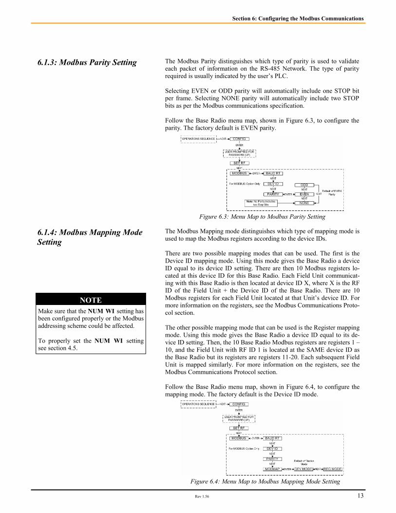
6.1.3: Modbus Parity Setting The Modbus Parity distinguishes which type of parity is used to validate each packet of information on the RS-485 Network. The type of parity required is usually indicated by the user’s PLC. Selecting EVEN or ODD parity will automatically include one STOP bit per frame. Selecting NONE parity will automatically include two STOP bits as per the Modbus communications specification. Follow the Base Radio menu map, shown in Figure 6.3, to configure the parity. The factory default is EVEN parity.
Section 6: Configuring the Modbus Communications
Figure 6.3: Menu Map to Modbus Parity Setting
6.1.4: Modbus Mapping Mode Setting
The Modbus Mapping mode distinguishes which type of mapping mode is used to map the Modbus registers according to the device IDs. There are two possible mapping modes that can be used. The first is the Device ID mapping mode. Using this mode gives the Base Radio a device ID equal to its device ID setting. There are then 10 Modbus registers lo-cated at this device ID for this Base Radio. Each Field Unit communicat-ing with this Base Radio is then located at device ID X, where X is the RF ID of the Field Unit + the Device ID of the Base Radio. There are 10 Modbus registers for each Field Unit located at that Unit’s device ID. For more information on the registers, see the Modbus Communications Proto-col section. The other possible mapping mode that can be used is the Register mapping mode. Using this mode gives the Base Radio a device ID equal to its de-vice ID setting. Then, the 10 Base Radio Modbus registers are registers 1 – 10, and the Field Unit with RF ID 1 is located at the SAME device ID as the Base Radio but its registers are registers 11-20. Each subsequent Field Unit is mapped similarly. For more information on the registers, see the Modbus Communications Protocol section. Follow the Base Radio menu map, shown in Figure 6.4, to configure the mapping mode. The factory default is the Device ID mode.
Figure 6.4: Menu Map to Modbus Mapping Mode Setting
NOTE Make sure that the NUM WI setting has been configured properly or the Modbus addressing scheme could be affected. To properly set the NUM WI setting see section 4.5.

Accutech Wireless Base Radio User Manual
14 Rev 1.56
The Base Radio connects to the Host (Master) system using Modbus over a serial RS-485 line. The Base Radio supports Modbus RTU transmission mode at baud rates of 9600, 19200, 38400, 57600, or 115200 baud with even, odd, or no parity and 8 data bits. One stop bit is used if even or odd parity is selected and two stop bits are used if the no parity option is se-lected to fill out the character frame to a full 11-bit character. Unless modified by the user, default values of 19200 baud, 8 data bits, even par-ity, and one stop bit are used. The Base Radio is always located at the device ID selected by the DEV ID menu item. Field units can be configured to either be assigned to an individual Modbus device ID or to holding registers within the Base Radio device ID through the appropriate selection in the MODMAP menu item. There are two MODMAP modes available: DEVMODE and REG-MODE. If the device ID mapping mode (DEVMODE) is selected, a Field Unit’s equivalent Modbus device ID is the Base Radio’s device ID plus the Field Unit’s RF ID. For example, if the Base Radio’s device ID was 10 and a Field Unit’s RF ID was 5, the Field Unit would be accessed under Modbus device ID 15. Using the device ID mapping mode adjusts the upper limit of the Base Radio’s device ID to 247 minus the number of Field Units on the RF network. For instance, if 5 Field Units were on the Base Radio’s network, the maximum Modbus device ID would be 242. If the register-mapping mode (REGMODE) is selected, a Field Unit’s data may be accessed with the Modbus Read Holding Register command (03) using the Base Radio’s device ID. The Base Radio uses register ad-dresses 1 through 10 with each subsequent group of 10 registers used by a Field Unit. The RF online/offline status of a Field Unit can be determined through a number of different sources. In the Base Radio holding registers, a count of the current number of online Field Units can be found at address 00004. Also the individual online/offline status of each Field Unit is stored in the Base Radio holding registers at addresses 00005, 00006, 00007, and 00008. These registers are bit field variables with each bit of the 16-bit number representing the status of a Field Unit. If the bit is set, the corre-sponding Field Unit is online. If the bit is cleared, the corresponding Field Unit is offline. In the Field Unit holding registers, bit 1 in the Field Unit & Sensor Status holding register holds the online/offline status of the particular device. Any Field Unit that is currently offline will return NaN (Not a Number) when queried for its primary or secondary measurement value. Note that if a Field Unit is online and is a single measurement device type, NaN will also be returned for the Secondary Sensor Value as the measurement does not exist in these devices.
6.2: Modbus Communication Protocol
NOTE This device supports Modbus RTU (Binary) communications. Note that the ASC-II transmis-sion mode is not supported.

Rev 1.56 15
Section 6: Configuring the Modbus Communications
6.3: Modbus Commands The Base Radio responds to six Modbus commands including the Read Holding Registers (03), Diagnostic (08), Get Com Event Count (11), Get Com Event Log (12), Report Slave ID (17), and Read Device Identifica-tion (43). The Read Holding Registers command provides the bulk of the functionality with the remaining commands being used for diagnostics/troubleshooting purposes. No other Modbus commands are supported and will be responded to with an ILLEGAL FUNCTION exception (code 01). A description of each command code is listed in the following sections.
6.3.1: Command 03- Read Holding Registers
This command is used to read the contents of a contiguous block of hold-ing registers in a Base Radio or Field Unit. If an invalid register address is requested, an ILLEGAL DATA ADDRESS exception (code 02) will be returned. The following sections will break down the holding registers for the Base Radio and Field Units, as well as how to understand the contents of the registers.
6.3.1.1: Base Radio Holding Registers
The following are the Base Radio holding registers for all mapping modes (i.e. Device ID and Register mapping modes):
6.3.1.1.1: Base Radio Device Type Registers
The Base Radio Device Type value is 255. This is the only possible value for the Device Type holding registers for a Base Radio. Note that the reg-ister is a 16-bit unsigned int for Base Radios.
6.3.1.1.2: Base Radio Device Status Registers
Value Base Radio Device Status 1 Base Radio Online
2+ Reserved For Future Use
Base Radio Holding Register (All Mapping Modes) Device ID: 1 To 247 Max.
Register Address Description Register Type 00001 Device Type 16-Bit Unsigned Int 00002 Device Status 16-Bit Unsigned Int 00003 Number of Field Units Expected 16-Bit Unsigned Int 00004 Number of Field Units Communicating 16-Bit Unsigned Int 00005 Online/Offline Status Of Field Units 1-16 16-Bit Unsigned Int 00006 Online/Offline Status Of Field Units 17-32 16-Bit Unsigned Int 00007 Online/Offline Status Of Field Units 33-48 16-Bit Unsigned Int 00008 Online/Offline Status Of Field Units 49-50 16-Bit Unsigned Int 00009 Reserved For Future Use 16-Bit Unsigned Int 00010 Reserved For Future Use 16-Bit Unsigned Int
The following are the values for the Device Status holding registers. These registers are bit field registers represented as a 16-bit unsigned int for Base Radios.

Accutech Wireless Base Radio User Manual
16 Rev 1.56
6.3.1.1.3: Base Radio On/Offline Field Unit Registers
On the left are the values for the Online/Offline Status of Field Units 1-16 holding register in the Base Radio. The other online/offline status holding registers hold the status of the remaining Field Units with RF IDs 17 through 50.
Value Field Unit Device Status 1 Field Unit 1 Online Status 2 Field Unit 2 Online Status 4 Field Unit 3 Online Status 8 Field Unit 4 Online Status
16 Field Unit 5 Online Status 32 Field Unit 6 Online Status 64 Field Unit 7 Online Status
127 Field Unit 8 Online Status 256 Field Unit 9 Online Status 512 Field Unit 10 Online Status
1024 Field Unit 11 Online Status 2048 Field Unit 12 Online Status 4096 Field Unit 13 Online Status 8192 Field Unit 14 Online Status
16384 Field Unit 15 Online Status 32768 Field Unit 16 Online Status
To decode the status register, take the value of the register and subtract the largest value listed in the table above that does not cause the result to be negative. Take the resulting total from the subtraction and subtract the next largest number possible and so on until the result is zero. Each value that was used in the subtraction indicates that the Field Unit is online. For example: The On/Offline Status holding register contains the value 15. In this case the largest value we can subtract is 8, which leaves a result of 7. Now we can subtract 4 from 7 and get 3. Now subtract 2 from 3 and we get 1. Finally we subtract 1 from 1 and get 0, so we are done. Which Field Units are online? We subtracted 8,4,2 and 1, and these numbers corre-spond to Field Units’ with RF IDs 1,2,3 and 4. In another example, say the On/Offline Status holding register contains the value 6. We can subtract 4 to get 2. Then we can subtract 2 to get 0. Thus Field Unit 2 and 3 are online, but Field Units 1 and 4 are offline.
6.3.1.2: Field Unit Holding Registers
The following are the Field Unit holding registers when used in the Device ID Mapping Mode (First Table) and the Register Mapping Mode (Second Table).
Field Unit Holding Registers (DEVMODE Only)
Device ID = Base Radio Modbus ID + RF ID
Register Address Description Register Type 00001 Device Type 32-Bit IEEE
Floating Point 00002 Device Type 00003 Device Status 32-Bit IEEE
Floating Point 00004 Device Status 00005 Primary Sensor Value 32-Bit IEEE
Floating Point 00006 Primary Sensor Value 00007 Secondary Sensor Value 32-Bit IEEE
Floating Point 00008 Secondary Sensor Value 00009 Tertiary Sensor Value 32-Bit IEEE
Floating Point 00010 Tertiary Sensor Value
Field Unit Holding Registers (REGMODE Only)
Device ID = Base Radio Modbus ID
Register Address Description Register Type 00001 + (RF ID * 10) Device Type 32-Bit IEEE
Floating Point 00002 + (RF ID * 10) Device Type 00003 + (RF ID * 10) Device Status 32-Bit IEEE
Floating Point 00004 + (RF ID * 10) Device Status 00005 + (RF ID * 10) Primary Sensor Value 32-Bit IEEE
Floating Point 00006 + (RF ID * 10) Primary Sensor Value 00007 + (RF ID * 10) Secondary Sensor Value 32-Bit IEEE
Floating Point 00008 + (RF ID * 10) Secondary Sensor Value 00009 + (RF ID * 10) Tertiary Sensor Value 32-Bit IEEE
Floating Point 00010+ (RF ID * 10) Tertiary Sensor Value
NOTE
If you have purchased any Wireless Differential Pres-sure Field Units, please see the User Manual for spe-cific Modbus holding regis-ter differences from those listed in the following sec-

Rev 1.56 17
Section 6: Configuring the Modbus Communications
6.3.1.2.1: Field Unit Device Type Registers
The following are possible values for the Device Type holding registers. Note that the register is a 32-bit floating point value for Field Units.
Value Device Type 0 Acoustic Monitor Field Unit 1 RTD Field Unit 2 Pressure Field Unit 3 Dual 0-10V Input Field Unit 4 Dual 4-20mA Input Field Unit 5 Thermocouple Field Unit 6 Reserved 7 Level Sensor Field Unit 8 Split RTD Field Unit 9 Split Pressure Field Unit
10 Split Dual Thermocouple Field Unit 11 Differential Pressure Field Unit (100 IN. H20) 12 Split Differential Pressure Field Unit (100 IN. H20) 13 Differential Pressure Field Unit (300 IN. H20) 14 Split Differential Pressure Field Unit (300 IN. H20) 15 Differential Pressure Field Unit (25 PSID) 16 Split Differential Pressure Field Unit (25 PSID) 17 Differential Pressure Field Unit (100 PSID) 18 Split Differential Pressure Field Unit (100 PSID) 19 Differential Pressure Field Unit (300 PSID) 20 Split Differential Pressure Field Unit (300 PSID)
6.3.1.2.2: Field Unit Device Status Registers
The following are the values for the Device Status holding registers. These registers are bit field registers represented as a 32-bit floating point value for Field Units.
Value Field Unit Device Status 1 Field Unit Online 2 Low Battery Condition 4 Alarm Condition 8 Sensor Error Condition
16 Sensor Overrange Condition 32 System Error Condition 64 Switch Input 1 High
127 Switch Input 2 High 256 Sq. Root Funct. ON (DP Only)
Again, like Section 6.3.1.1.3, the status can be resolved by subtracting the largest number listed above from the value received from the holding reg-ister, and then subtracting the next highest and so on until the result is 0. Each of the values used indicate the respective condition listed above. E.g., holding register reads 12, then subtract 8 and get 4. Then subtract 4 from 4 and get 0. Thus we have a sensor error and alarm condition from the list above.

Accutech Wireless Base Radio User Manual
18 Rev 1.56
6.3.2: Command 08- Diagnostic This command provides a number of tests for checking the communica-tions between the Base Radio and the Host master device.
Sub-function Code Field Unit Device Status
0 Return Query Data 1 Restart Communications Option 2 Return Diagnostics Register
3 Change ASC-II Input Delimiter (NOT SUPPORTED)
4 Force Listen Only Mode 5-9 NOT USED 10 Clear Counters & Diagnostics Register 11 Return Bus Message Count
12 Return Bus Communication Error Count
13 Return Bus Exception Error Count 14 Return Slave Message Count 15 Return Slave No Response Count 16 Return Slave NAK Count 17 Return Slave Busy Count 18 Return Bus Character Overrun Count
19+ NOT USED
Note that identical information is returned for any device ID that the Base Radio has control of (i.e. including Field Units mapped to virtual device IDs when operating in the device ID mapping mode (See Section 6.2).
6.3.3: Command 11- Get Com Event Counter
This command returns a two-byte status word and the device’s event counter. The status word will either be 0 or 65535 if the previous com-mand is still being processed. The event counter is incremented for each successful message received. The counter is not incremented for com-mands that return exception responses or commands that fetch event counters. The event counter will eventually roll over to 0 after reaching a count of 65535. Note that identical information is returned for any device ID that the Base Radio has control of (i.e. including Field Units mapped to virtual device IDs when operating in the device ID mapping mode). For further details on this command, please consult the Modbus protocol specification.

Rev 1.56 19
6.3.4: Command 12- Get Com Event Log
This command returns a status word, communications event counter, mes-sage count, and a field of bytes from the communications event log. The status word and communications event counter are identical to those re-turned by Command 11 (Get Com Event Counter) above. The message count is a count of the total number of messages received by this device, including messages intended specifically for this device as well as other devices on the Modbus network. The event log keeps track of information on the last 7 communications events. Note that identical information is returned for any device ID that the Base Radio is controlling (i.e. includ-ing Field Units mapped to virtual device IDs when operating in the device ID mapping mode). For further details on this command, please consult the Modbus protocol specification..
6.3.5: Command 17- Report Slave ID
This command returns the device type, device status, and a run indicator status byte. The 16-bit device type and device status words are identical to those held in the holding registers. The run indicator status byte is 255 (0xFF hex) if the device is online and 0 (0x00 hex) if the device is offline. Unlike some of the other diagnostics commands, different information is returned depending on whether the device ID used in this command corre-sponds to the Base Radio or one of the Field Units mapped to a device ID when operating in the device ID mapping mode. For further details on this command, please consult the Modbus protocol specification.
6.3.5: Command 43- Read Device ID
This command returns identification information relating to the device. The conformity level of this command is level 01, basic identification (stream access only). As with most of the other diagnostic commands, identical information is returned for any device ID that the Base Radio is controlling (i.e. including Field Units mapped to virtual device IDs when operating in the device ID mapping mode). For further details on this command, please consult the Modbus protocol specification.
Accutech Wireless Base Radio User Manual
20 Rev 1.56
Configuring the Analog Output Loop
Section 7
The following sections only apply if you have purchased the Analog Out-put option. If you have ordered the Analog Output (AO) option for the Base Radio then the single 4-20mA analog output loop on the Base Radio has been enabled, and the following menu options are available in the Base Radio to support the configuration of this option. The subsections are as follows:
7.1: Trimming the Output Loop 7.2: Selecting the Failsafe Output 7.3: Selecting Which Field Unit is Output
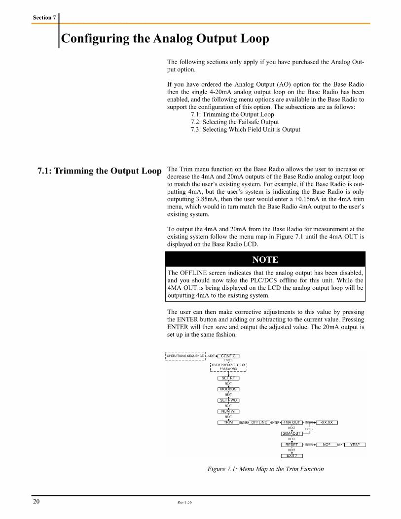
7.1: Trimming the Output Loop The Trim menu function on the Base Radio allows the user to increase or decrease the 4mA and 20mA outputs of the Base Radio analog output loop to match the user’s existing system. For example, if the Base Radio is out-putting 4mA, but the user’s system is indicating the Base Radio is only outputting 3.85mA, then the user would enter a +0.15mA in the 4mA trim menu, which would in turn match the Base Radio 4mA output to the user’s existing system. To output the 4mA and 20mA from the Base Radio for measurement at the existing system follow the menu map in Figure 7.1 until the 4mA OUT is displayed on the Base Radio LCD.
The user can then make corrective adjustments to this value by pressing the ENTER button and adding or subtracting to the current value. Pressing ENTER will then save and output the adjusted value. The 20mA output is set up in the same fashion.
NOTE The OFFLINE screen indicates that the analog output has been disabled, and you should now take the PLC/DCS offline for this unit. While the 4MA OUT is being displayed on the LCD the analog output loop will be outputting 4mA to the existing system.
Figure 7.1: Menu Map to the Trim Function

Rev 1.56 21
In the event of an RF or Sensor Error or long duration with no RF contact between the Base Radio and any of the Field Units, the Base Radio will output a Failsafe signal on the analog output loop. The Failsafe has the option to be enabled/disabled and the option (if en-abled) to output “high” or “low” mA signal. High is denoted as being 23mA and Low is denoted as being 3.6mA The factory default is disabled and low.
7.2: Selecting the Failsafe Output
Example If a GP-250 Field Unit was selected, you might want 4mA to be equivalent to 0 PSI. Then you would enter 000.00 under the SET LRV function. But the process goes to a maximum of 180 PSI. Then to increase resolution of the process variable being monitored you might want the 20mA to be equivalent to 200 PSI. Then you would enter 200.00 under the SET URV function.
Figure 7.2: Menu Map to the Failsafe Output Setting The Single output option allows the user to select one of the Field Units on the Base Radio Network, and then have that Field Units Input 1 ranged over the 4-20mA output loop of the Base Radio.
7.3: Selecting Which Field Unit is Output
Figure 7.3: Menu Map to the Output Option Setting Pressing the ENTER button while RF ID is displayed on the Base Radio LCD will allow the user to enter the RF ID of the Field Unit to be output on the Analog Output. Once the Unit to be output on the analog loop is displayed press the EN-TER button. This will display the RANGE selection as seen in Figure 7.3. Pressing ENTER will allow the user to range the process variable Field Unit with the respective RF ID. The user will then be displayed SET LRV. This refers to the Lower Range Value. To properly set this value you should press ENTER and enter the Process Variable value you want 4mA to represent. Do the same for the SET URV function. This will have ranged your Input 1 Process Variable over the 4-20mA loop.

Accutech Wireless Base Radio User Manual
22 Rev 1.56
Power Characteristics • 10VDC-30VDC, 24 VDC @ 200mA typical RF Characteristics • 902 MHz – 928 MHz Frequency Hopping Spread Spectrum (FHSS), FCC certified ISM li-
cense-free band • Up to 3000’ range to field units with clear line of sight; 500’ to 1000’ range with obstructions • The RF module in each field unit is individually tested and calibrated over the full temperature
range to ensure reliable wireless operation Output Options • RS-485 digital communications (WI-BR-I-XP) with conversion to RS-232 or USB for interface
with PC or server and Wireless Instrumentation Manager (WIM) (optional) • Single 4-20 mA analog (WI-BR-I-XP-AO) • Serial Modbus RTU (Binary) (WI-BR-I-XP-MOD) over RS-485 • Modbus over TCP/IP (via optional converter) Accuracy • 4-20 mA is Opto-isolated • Isolation voltage = 800 V • 9 V minimum loop voltage • 4 uA resolution • Accuracy of 10 µA at 25 °C (reference conditions) • Ambient Temperature effect ±0.1% of reading per 18°F (10°C) • Supply rejection less than 2 µA from 9-28 V Physical Characteristic • Baked enamel explosion-proof, weather-proof and corrosion-proof housing • Electromagnetic Compatibility • (CE Compliance) • Operates within specification in fields from 80 to 1,000 MHz with field strengths to 30 V/m.
Meets EN 50082-1 general immunity standard and EN 55011 compatibility emissions standard Industrial Certification • Rated for industrial use -40°F to 185°F(-40°C to 85°C) • NEMA 4X explosion-proof housing
Technical Specifications
Section 8
Figure 8.1: Overall Base Radio Dimensions

Rev 1.56 23
Navigating the Menus
Appendix A
Pressing either the NEXT or ENTER buttons located on the front of the Field Unit or Base Radio just below the Liquid Crystal Display (LCD) screen is all that is needed to navigate the respective menus. Pressing both of these buttons for one second will turn the unit on. Pressing the NEXT button at any time while the Base Radio is cycling through the normal messages causes the Base Radio to enter the setup mode. The NEXT button is then used to step through menu options, and the ENTER button is used to enter a submenu of what is displayed on the LCD at that time. If no button is pressed within a 30 second period the unit goes back to the normal display mode. If you enter a submenu that requires a numerical input, such as 001, the leftmost 0 will be blinking. This indicates that pressing the NEXT button will increment this value with each press from 0 to 9 and back to 0 again. Pressing the ENTER button will move to the next available value. If the last value is blinking, pressing ENTER will save the entered values and return to the return from the sub menu.

Accutech Wireless Base Radio User Manual
24 Rev 1.56
Base Radio Menu Map
Appendix B


______________________________________________________________________________________________________________________________________ A Division of Adaptive Instruments Corp. 577 Main Street · Hudson, MA 01749 U.S.A. TEL: 800-879-6576 · 978-568-0500 FAX: 978-568-9085 Email: [email protected] www.accutechinstruments.com
A B O U T U S .
Accutech, a division of Adaptive Instruments Corp., is a lead-ing edge, technology-driven developer, manufacturer and supplier of embedded microprocessor-based electronics. Based in Hudson, Massachusetts, Accutech is the most suc-cessful leading independent producer of wireless instrumen-tation on the market today. Accutech customers include large national companies in the oil and gas, chemicals, pharmaceutical, food and beverage, primary materials processing, and energy industries. In addi-tion to the wireless product line, Accutech also offers a tradi-tional wired line of temperature, pressure and differential pressure instrumentation. In the process control field, where quality is taken for granted and new technology is announced daily, we have deliberately concentrated our efforts on the development of instrumenta-tion that makes business sense. The result is a product range that is rugged, secure, and reliable and works in even the most hazardous environments. We give companies the tools to reduce costs, save time, enhance safety, improve environ-mental performance and cut waste. The next industrial revolution is right now. Let Accutech show you how to realize gains in operating efficiency.
Visit us at: www.accutechinstruments.com Or call us at +1 800 879-6576 Specifications subject to change without notice. Printed in USA. Copyright 2005 Adaptive Instruments, Corp.