BaSE-II: A Robust and Experimental Galileo PRS Receiver ... · PDF fileBaSE-II: A Robust and...
13
BaSE-II: A Robust and Experimental Galileo PRS Receiver Development Platform Alexander Rügamer, Philipp Neumaier, Philipp Sommer, Fabio Garzia, Günter Rohmer, Fraunhofer IIS, Germany Andriy Konovaltsev, Matteo Sgammini, Stefano Caizzone, Michael Meurer, German Aerospace Center (DLR), Germany Jan Wendel, Frank Schubert, Airbus Defence & Space, Germany Stefan Baumann, IABG, Germany BIOGRAPHY Alexander Rügamer received his Dipl.-Ing. (FH) degree in Electrical Engineering from the University of Applied Sciences Würzburg-Schweinfurt, Germany in 2007. Since the same year he works at the Fraunhofer Institute for Integrated Circuits IIS in the field of GNSS receiver development. He was promoted to Senior Engineer in February 2012. Since April 2013 he is head of a research group dealing with secure GNSS receivers and receivers for special applications. His main research interests focus on GNSS multi-band reception, integrated circuits and immunity to interference. Philipp Neumaier received his Dipl.-Ing. degree in Electrical Engineering from the University of Stuttgart, Germany in 2008. Since 2009 he works at the Fraunhofer Institute for Integrated Circuits IIS in the field of GNSS receiver development with the emphasis of the digital baseband design. Philipp Sommer received his Dipl.-Inf. degree in Computer Science from the Friedrich-Alexander- University, Erlangen-Nuremberg, Germany in 2010. Since the same year he works at the Fraunhofer Institute for Integrated Circuits IIS in the field of GNSS receiver development. His main task is the development of embedded system software which includes the planning and realization of the architecture for GNSS applications. Fabio Garzia received his Master of Science degree in Electronic Engineering from the University of Bologna, Bologna, Italy in 2005. In 2009 he received his PhD degree from the Tampere University of Technology (TUT), Finland and continued his job as senior researcher at the TUT. Since 2011 he works in the Navigation team at Fraunhofer IIS, Nuremberg where he is charge of the development of SoCs and specialized hardware modules for GNSS receiver. Günter Rohmer received his Dipl.-Ing. degree in Electrical Engineering in 1988 and the PhD in 1995 from the University of Erlangen, Germany. From 2001 till 2014 he has been head of a department at the Fraunhofer Institute for Integrated Circuits dealing with the development of components for satellite navigation receivers, indoor navigation and microwave localization systems. Since 2014 he is head of the general localization division of Fraunhofer IIS. Andriy Konovaltsev received his engineer diploma and the Ph.D. degree in electrical engineering from Kharkov State Technical University of Radio Electronics, Ukraine in 1993 and 1996, correspondingly. He joined the Institute of Communications and Navigation of DLR in 2001. His research interests are in array processing for satellite navigation systems, signal processing algorithms for navigation receivers including synchronization, multipath and radio interference mitigation. Matteo Sgammini received the BEng degree in electrical engineering in 2005 from the University of Perugia. He joined the Institute of Communications and Navigation of the German Aerospace Center (DLR) in 2008. His field of research is interference detection and mitigation for global navigation satellite systems (GNSS). Stefano Caizzone received the M.Sc. degree in Telecommunications Engineering from the University of Rome “Tor Vergata” in 2009. He is now with the Antenna group of the Institute of Communications and Navigation of the German Aerospace Center (DLR), where he is responsible for the development of innovative miniaturized antennas. His main research interests concern small antennas for RFIDs and navigation, antenna arrays and grids with enhanced sensing capabilities. Michael Meurer received the diploma in Electrical Engineering and the Ph.D. degree from the University of Kaiserslautern, Germany. After graduation, he joined the Research Group for Radio Communications at the Technical University of Kaiserslautern, Germany, as a senior key researcher, where he was involved in various
Transcript of BaSE-II: A Robust and Experimental Galileo PRS Receiver ... · PDF fileBaSE-II: A Robust and...

BaSE-II: A Robust and Experimental Galileo PRS Receiver Development Platform
Alexander Rügamer, Philipp Neumaier, Philipp Sommer, Fabio Garzia, Günter Rohmer, Fraunhofer IIS, Germany
Andriy Konovaltsev, Matteo Sgammini, Stefano Caizzone, Michael Meurer, German Aerospace Center (DLR), Germany Jan Wendel, Frank Schubert, Airbus Defence & Space, Germany
Stefan Baumann, IABG, Germany
BIOGRAPHY Alexander Rügamer received his Dipl.-Ing. (FH) degree in Electrical Engineering from the University of Applied Sciences Würzburg-Schweinfurt, Germany in 2007. Since the same year he works at the Fraunhofer Institute for Integrated Circuits IIS in the field of GNSS receiver development. He was promoted to Senior Engineer in February 2012. Since April 2013 he is head of a research group dealing with secure GNSS receivers and receivers for special applications. His main research interests focus on GNSS multi-band reception, integrated circuits and immunity to interference. Philipp Neumaier received his Dipl.-Ing. degree in Electrical Engineering from the University of Stuttgart, Germany in 2008. Since 2009 he works at the Fraunhofer Institute for Integrated Circuits IIS in the field of GNSS receiver development with the emphasis of the digital baseband design. Philipp Sommer received his Dipl.-Inf. degree in Computer Science from the Friedrich-Alexander-University, Erlangen-Nuremberg, Germany in 2010. Since the same year he works at the Fraunhofer Institute for Integrated Circuits IIS in the field of GNSS receiver development. His main task is the development of embedded system software which includes the planning and realization of the architecture for GNSS applications. Fabio Garzia received his Master of Science degree in Electronic Engineering from the University of Bologna, Bologna, Italy in 2005. In 2009 he received his PhD degree from the Tampere University of Technology (TUT), Finland and continued his job as senior researcher at the TUT. Since 2011 he works in the Navigation team at Fraunhofer IIS, Nuremberg where he is charge of the development of SoCs and specialized hardware modules for GNSS receiver. Günter Rohmer received his Dipl.-Ing. degree in Electrical Engineering in 1988 and the PhD in 1995 from
the University of Erlangen, Germany. From 2001 till 2014 he has been head of a department at the Fraunhofer Institute for Integrated Circuits dealing with the development of components for satellite navigation receivers, indoor navigation and microwave localization systems. Since 2014 he is head of the general localization division of Fraunhofer IIS. Andriy Konovaltsev received his engineer diploma and the Ph.D. degree in electrical engineering from Kharkov State Technical University of Radio Electronics, Ukraine in 1993 and 1996, correspondingly. He joined the Institute of Communications and Navigation of DLR in 2001. His research interests are in array processing for satellite navigation systems, signal processing algorithms for navigation receivers including synchronization, multipath and radio interference mitigation. Matteo Sgammini received the BEng degree in electrical engineering in 2005 from the University of Perugia. He joined the Institute of Communications and Navigation of the German Aerospace Center (DLR) in 2008. His field of research is interference detection and mitigation for global navigation satellite systems (GNSS). Stefano Caizzone received the M.Sc. degree in Telecommunications Engineering from the University of Rome “Tor Vergata” in 2009. He is now with the Antenna group of the Institute of Communications and Navigation of the German Aerospace Center (DLR), where he is responsible for the development of innovative miniaturized antennas. His main research interests concern small antennas for RFIDs and navigation, antenna arrays and grids with enhanced sensing capabilities. Michael Meurer received the diploma in Electrical Engineering and the Ph.D. degree from the University of Kaiserslautern, Germany. After graduation, he joined the Research Group for Radio Communications at the Technical University of Kaiserslautern, Germany, as a senior key researcher, where he was involved in various

international and national projects in the field of communications and navigation. Since 2005 he has been an Associate Professor (PD) at the same university. Additionally, since 2006 Dr. Meurer is with the German Aerospace Centre (DLR), Institute for Communications and Navigation, where he is the director of the Department of Navigation and of the Centre of Excellence for Satellite Navigation. In addition, since 2013 he is a professor of electrical engineering and director of the Institute of Navigation at the RWTH Aachen University. His current research interests include GNSS signals, GNSS receivers, interference and spoofing mitigation and navigation for safety-critical applications. Jan Wendel received the Dipl.-Ing. and Dr.-Ing. degrees in Electrical Engineering from the University of Karlsruhe in 1998 and 2003, respectively. From 2003 until 2006 he was an assistant professor at the University of Karlsruhe, where his research interests focused on integrated navigation systems and MAV flight control. Since 2006, he is private lecturer at the University of Karlsruhe. In 2006, Jan Wendel joined MBDA in Munich. Since 2009, he is with EADS Astrium GmbH (now Airbus Defence & Space) in Munich, where he is involved in various activities related to satellite navigation including tracking algorithms, compatibility analysis, and interference detection and characterization. Frank Max Schubert graduated in 2007 in Electrical Engineering and Information Technology at the Karlsruhe Institute of Technology in Germany. From 2007 until 2011 he was member of the scientific staff at the Institute of Communications and Navigation of the German Aerospace Center (DLR). From 2009 until 2012 F. M. Schubert was an external Ph.D. student in the Navigation and Communications Section at Aalborg University (AAU), Denmark. He obtained the Ph.D. degree from AAU in wireless communications in October 2012. Since November 2012 he is a system engineer for navigation signals at Airbus Defense & Space (formerly EADS Astrium) in Ottobrunn, Germany. Stefan Baumann received his diploma in Physical Geography in 1995 from the Ludwig-Maximilians-University Munich and his PhD in 2002 from the Heinrich-Heine-University Duesseldorf. He is involved in GNSS- and Galileo-activities since 1996 and joined IABG in 2006 as Project Manager for security-related radio- and satellite projects. ABSTRACT This paper features an experimental Galileo PRS receiver with a novel BOC tracking method and interference mitigation algorithms in time, frequency and spatial domain. The modified BaSE-II hardware architecture is outlined including a newly designed miniaturized 2x2
array antenna. A new, reliable and robust BOC tracking method is presented that fully exploits the subcarrier accuracy and allows reliable, fast and robust detection and correction of false locks to side peaks. Finally the implemented interference mitigation techniques are described with keeping the special PRS requirements in mind. DISCLAIMER All information presented and discussed within this paper is part of the public domain. The PRS information used in the paper is freely available e.g. through the GIOVE-A+B Public SIS ICD [1]. No classified documents or information were used. Consequently, the presented receiver will differ in various aspects to real Galileo PRS receivers. INTRODUCTION The increasing use of GNSS for military and security-related applications is generating a higher demand for robust position/navigation solutions. Galileo’s Public Regulated Service (PRS) targets governmental approved organizations including public safety & security, defense, and operators of critical Infrastructures like telecommunication- and energy-networks as well as critical transports. A PRS receiver has to deliver robust, reliable, and continuous position information even under challenging reception conditions as well as in jammed environments, requiring a considerable robustness against interference. In addition, protection against signal meaconing and spoofing has to be provided. The Galileo system design supports these functions of the PRS receiver by featuring two encrypted signals on two frequency bands. All these features make PRS receiver development a very demanding task. Within the BaSE (Bavarian security receiver) project, a consortium consisting of six Bavarian companies and research institutes was formed to investigate core technologies, acquire necessary know-how, and to develop a high-end Galileo PRS receiver prototype. The consortium consists of Fraunhofer Institute for Integrated Circuits (IIS), Institute of Communications and Navigation of German Aerospace Center (DLR), IABG, Airbus Defense & Space (formerly EADS Astrium), NavCert, and Siemens. The project is co-financed and supported by the Bavarian Ministry of Economic Affairs. At ION GNSS 2011 we presented the BaSE project the first time [2]. The BaSE-I project started in 2010 and was completed with the demonstration of an initial PRS prototype receiver in early 2012. Within BaSE-I, we developed key technologies for Galileo PRS receivers

including a versatile receiver platform, the analysis of potential security module architectures, and first verification of functional implemented cryptographic. Moreover, the focus of the BaSE-I project was on tracking the ambiguous binary offset carrier (BOC) modulated signals with a double estimator (DE) correlator and to implement interferer mitigation by means of an adaptive 2x2 array processing. In the successor project BaSE-II – timeframe 2012-2014 – the objective is to finalize all essential components needed for an experimental Galileo PRS receiver demonstrator and their integration on a functional level. In addition, BaSE-II focuses more on interference mitigation on the receiver level, like the detection of interference, the usage of adaptive filter algorithms for interference suppression, meaconing and spoofing detection based on correlation function analysis and spatial filtering. Moreover, BaSE-II features a new robust BOC tracking algorithm combined with a single sideband tracking depending on the interference environment. Other non-technical goals of BaSE-I and –II are the identification of national users and applications for Galileo PRS, the analysis of their specific requirements, the coordination with national and European PRS interfaces, projects, and developments as well as the elaboration and integration of a capable IT-security concept into the receiver system, and aspects related to future standardization and certification of PRS receivers. Integration of PRS receivers into the whole Galileo PRS-Management and Security infrastructure is a further task performed within the BaSE-II project, with basic considerations on combined PRS/PMR (TETRA) and PRS/GPS PPS use. Moreover, a preliminary key-loading and –management interface has been developed. The paper is structured as follows: In the next Section, the signals employed for the Galileo PRS service are reviewed. Then, the BaSE receiver hardware is described, followed by a discussion of the signal processing techniques for BOC tracking. The fourth section describes the implemented interference mitigation techniques in time, frequency and spatial domain before we draw conclusions. GALILEO PRS SIGNALS Galileo PRS signals are transmitted in a coherent way together with the Open Service (OS) and Commercial Service (CS) signals over the E1A and E6A frequency bands, using a binary offset carrier modulation denoted as BOCc(15,2.5) and BOCc(10,5), respectively. BOCc uses a cosine phased subcarrier resulting in higher frequency components than a sine phased subcarrier used in BOCs modulations of e.g. Galileo E1BC OS. As a result, more
energy is shifted to the edges of the band. This improves the spectral separation with the coexisting OS and CS signals and the theoretical tracking performance. The autocorrelation function (ACF) of the Galileo PRS BOCc(10,5) and a BOCc(15,2.5) signals are shown in Figure 1. The multiple positive and negative peaks are clearly visible. An overview of the Galileo PRS signals on E1 and E6 is given in Table 1.
Figure 1: BOCc(15,2.5) and BOCc(10,5) ACFs Table 1: Galileo PRS signals
GNSS Signal
Carrier Frequency (MHz) Modulation
Galileo E1A PRS 1575.42 BOCc(15,2.5)
Galileo E6A PRS 1278.75 BOCc(10,5)
The access to the PRS is controlled by the Galileo Member States through an encryption key system. The standard user will not be able to access any information of Galileo PRS. A PRS security module is necessary to generate the PRS pseudo-random-noise (PRN) sequences and to process their messages. Within BaSE-II a functional software security module was developed but not integrated in the BaSE-II receiver to keep the demonstrator unclassified. To be able to still test and demonstrate the receiver’s capability to handle the PRS BOCc modulations, pseudo-PRS signals are used instead the real ones. The Spirent signal generators we use for testing and demonstration support unclassified PRS noise or what we call “pseudo-PRS”. The pseudo-PRS PRNs are derived from a GPS P-code generator: the Galileo PRS E1A modulation with a chipping rate of 2.5 MChips/s uses every fourth, the E6A signal with a chipping rate of 5 MChips/s uses every second chip of the 10 MChip/s GPS P-code. The pseudo-PRS PRNs are then modulated

PC, Linux OS
ConfigurationE6_
LO
E1_
LO
AD
C-C
lock
Clock / Local Oscillator
10 M
Hz
Ref
in
E1_
LO
AnalogRF-Front-end
Data Recording
AN
T_4–
E6
19" Rack
Array-Antenna E1/E6
PVT
Beamforming
E6_
LO
AN
T_4–
E1
AN
T_3–
E6
AN
T_3–
E1
AN
T_2–
E6
AN
T_2–
E1
AN
T_1–
E6
AN
T_1–
E1
DigitalFront-end
AD
C-C
lock
IF_4
–E6
IF_4
–E1
IF_3
–E6
IF_3
–E1
IF_2
–E6
IF_2
–E1
IF_1
– E6
IF_1
–E1
IF_4
–E6
IF_4
–E1
IF_3
–E6
IF_3
–E1
IF_2
–E6
IF_2
–E1
IF_1
–E6
IF_1
–E1
VG
A-C
ontro
l
VG
A-C
ontro
lDi
gita
l Raw
IF D
ata
16.8
Gbi
t/s
RF Front-End Sub-System
Acquisition, Tracking and PVT Sub-System
InterferenceMitigation
BaS
E-A
PIBaseband
FPGA BoardPCIe
HW-Acquisition Unit, Versatile Tracking
Channels with - EPL Correlator, - Double Estimator,- Astrium Correlator
Tracking-loops
MGT MGT
E6_
Cal
E1_
Cal
Calibration Signal Generator
E6_ LO
E1_LO
E6_
LO
E1_
LO
10 M
Hz
Ref
out
>50 MHz Bandwidth 14bit I/Q ADC@75 MHz
Pulse Blanking, Adaptive Filters
and Notch
Frequency Domain AdaptiveFiltering (FDAF)
InterferenceMitigation
FPGA
Figure 2: BaSE-II receiver block diagram together with their OS/CS components in a valid Spirent scenario. More details about Spirent’s PRS noise can be found in [3]. BASE RECEIVER HARDWARE Receiver Architecture An overview of the receiver architecture is depicted in Figure 2. A 4-element dual-frequency (E1 and E6) array antenna is used to set the basis for protection against signal meaconing and spoofing with high interference mitigation capabilities. The BaSE-II receiver incorporates a calibration transmitter featuring OS and pseudo-PRS signals for a receiver self-calibration. The analog signal conditioning (filtering, amplification, down-conversion) is done in separate quadruple radio frequency (RF) analog front-ends for E1 and E6, respectively. The analog-to-digital conversion (ADC) with digital signal conditioning is carried out in the successive digital front-ends. One digital front-end is used for the four E1 channels and one for the four E6 channels. All necessary clock signals (for the ADCs and the FPGAs) and local oscillator (LO) signals (for the analog mixer stages) are coherently derived and distributed on a dedicated clock and local oscillator generation module. Using an optical multi-gigabit transceiver link (MGT), the digital raw data from the digital front-ends are transferred to the pre-correlation interference mitigation module whose output is finally fed into the baseband receiver hardware, again using an optical MGT. All computationally demanding tasks like
the acquisition and the correlators are implemented on the digital baseband FPGA. The tracking loops are closed in software running on a standard PC over a PCIe link where both the beamforming and the PVT with RAIM and spoofing detection are also implemented.
Figure 3: BaSE-II integration without antenna

Figure 4: The manufactured 2x2 antenna array for Galileo E1/E6 bands
Figure 5: Stackup of the designed antenna
Figure 6: Realized gain at boresight for the 4 antennas when measured singularly on a ground plane with diameter of 200 mm
Figure 7: Realized gain at boresight for the 2x2 array, either in embedded (dotted lines) or array configuration (straight line)
The hardware setup of the BaSE-II receiver is depicted in Figure 3, excluding the antenna. The RF front-end sub-system is realized using six units of height modules. The interference mitigation module as well as the baseband FPGA are installed within a standard 19” rack PC. An optical cable patch panel gives the possibility to include or exclude the interference mitigation module for different signal combinations. All these components are mounted in a 19” desk chassis using overall 12 units of height. Miniaturized E1/E6 array antenna The design of the BaSE-II antenna, depicted in Figure 4, had the aim to develop and manufacture a miniaturized 2x2 antenna array for robust navigation. This was obtained by choosing a capacitively-coupled stacked patch antenna technology, for operation at E6 and E1 Galileo bands. Using the capacitively-coupled feeding technique and a relatively thick substrate material (7.5 mm in total for the radiation part), full bandwidth coverage can be reached, while footprint compactness (the ground plane has a length of only 135 mm) is achieved by using a relatively high dielectric constant
(DK) material (ROGERS RO6010 with DK~10). The stackup of the antennas is shown in Figure 5. The results for the manufactured antennas are shown in Figure 6 and Figure 7: in particular, Figure 6 shows the realized gain of the antennas measured singularly on a ground plane with diameter of 200 mm, showing how dual-band behavior with gain values respectively of 5 and 2 dBic is obtained. Figure 7 on the other hand, shows the realized gain of the 2x2 array, either in embedded configuration (i.e. when only one antenna is fed) or in array mode (i.e. when all antennas are fed uniformly). Due to close vicinity, mutual coupling effects are present, hence causing crosstalk as well as radiation pattern distortion and subsequent decrease in gain values at boresight. The antennas, although packed in a small footprint, deliver nevertheless more than satisfactory performance, enabling advanced array signal processing capabilities.

Figure 8: BaSE-II baseband architecture block diagram Baseband Hardware The block diagram of the BaSE-II baseband design is depicted in Figure 8. Eight MGT are used to receive the filtered and preprocessed digital data stream with a total of 16.8 Gbit/s (four channels E1, four channels E6 with 75 MSPS @ 14 bit I/Q each). A 6-out-of-14 bit multiplexer allows selecting the six effective bits to be used for the further baseband processing. At this stage it is also possible to do a parallel snapshot of either four E1 or four E6 signal to a so called covariance storage for the analysis of the different reception elements from the 2x2 beamforming antenna used. The four E1 signals as well as the four E6 signals can be assigned to any of the available tracking channels at run-time. This can be done in software by setting the value of a dedicated multiplexer. There are two different baseband FPGA hardware designs: one experimental with three different types of correlators in parallel (Standard early-prompt-late (STD) or (EML), Double Estimator (DE), Astrium Correlator (AC)) and one with 32 channels of the Astrium Correlator only [4]. The different correlators are described and compared in Section “GNSS Signal Processing”.
The system is equipped also with a dedicated hardware Fast-Fourier Transform (FFT) acquisition module. The module is able to perform a parallel code phase search in the Fourier domain based on a 16K FFT. This enables a fast detection of the satellites of the L1/E1 bands with their respective code delays and Doppler frequencies. These Doppler results can have an accuracy of 2 Hz by using a pre-acquisition search step [5]. This guarantees a faster and more reliable transition to the tracking. The dedicated memories present in the FFT module can be used to make a snapshot from one of the eight incoming signals. The antenna and the band can be selected at run-time. Up to 81,920 6 bit I/Q samples at 75 MHz sampling rate can be stored and sent to the PC for offline analysis. This corresponds to a 1.09 ms recorded signal length with a frequency resolution of 915 Hz. This enables sophisticated spoofing detection methods, for example by monitoring the 2D-acquisiton search space, as well as interferer detection and characterization methods by employing short-time Fourier transforms (STFT). The user application running on the desktop PC controls these GNSS modules through a PCIe interface. From the

structural point of view, the PCIe core is connected to a hierarchical on-chip Advanced Microcontroller Bus Architecture (AMBA) composed of a high-performance bus (AHB) and a peripheral bus (APB). The AHB provides a direct connection between the PCIe core and the real-time tracking modules for the loops closure. The APB is mainly used to write and read the control and status registers of the different GNSS modules. High speed MGT interface The communication between the digital front-ends and the baseband module is based on the multi-gigabit transceiver cores (MGT) provided by Xilinx in the 6-series devices. Each MGT transceiver of the Spartan6 device used in the digital front-end module transmits a stream of 28 bit complex data at 75 MHz for a total of 2.1 Gbit/s. Only one channel per link is used, since the total bandwidth is close to the maximum supported by the MGT. Each Spartan6 device has two dual-MGT transceivers for a total speed of up to 8.4 Gbit/s. The resulting eight data streams coming from the two Spartan6 devices are then received by the eight GTX modules of the Virtex6 device. Altogether this corresponds to a continuous data rate of 16.8 Gbit/s. This is not the full rate allowed by our implementation, since at the moment we use only 28 out of the 32 bit available per channel and per link. The remaining four bits could be used in future for the transmission of additional status information. Calibration signal generation Additionally, the receiver incorporates a calibration transmitter featuring GPS C/A, Galileo OS and pseudo-PRS signals for a beamforming online calibration. The baseband core is able to generate a pseudo satellite signal with a similar modulation and PRN code as received in the E1 and E6 bands. This digital output signal is handed over to a calibration generation unit that converts the digital signals to the analog domain and moves the signal spectrum content to the corresponding frequency bands. The calibration generator output signal is then fed to a calibration input port of the array antenna. This self-generated signal appears as an additional satellite transmission in the outputs of the array antenna and can be tracked in parallel to the regular satellites. The carrier phase observations collected by tracking the calibration signal at different antenna channels allow to calibrate the long-term relative cross-antenna phase offsets and compensate for phase drifts occurring due to the RF front-ends and connecting cables. The calibration signal generation core is implemented on the same Virtex6 device of the baseband system, but it is completely independent from it and is characterized by an isolated clock domain.
BaSE-API / Software-Assisted Hardware Receiver Using an application programming interface (API) the baseband FPGA can be controlled via a high-speed PCIe interface and the tracking loops closed in software on a standard Linux-PC. This approach uses the advantages of the fast parallel FPGA processing while still providing the flexibility of a software receiver. External modules like beamforming or tracking can register with the receiver stub by calling register_*cb functions of the API. These callback functions will be executed when a certain event occurs. With this architecture, flexibility is guaranteed by modularity. Low latency hardware access and a fast event handling provide a robust tracking performance. A new feature of the API is the ability to switch the modulation of a channel during runtime. This is necessary for a transition from Galileo OS to pseudo-PRS tracking or in a previous stage from GPS L1 C/A to GPS P-Code tracking. Therefore each channel is equipped with a L1 C/A and a P-Code generator. Once L1 C/A tracking is in lock and steadily decoding the navigation message it can initialize the P-Code generators with the Z-Count. After the code generator has been initialized the software must determine the timestamp when to switch to P-Code tracking to be properly aligned with the epoch of the current time of week (TOW). The hardware automatically switches the modulation to BPSK(10) and adjusts the correlator tap spacing accordingly. For pseudo-PRS tracking the transition works similar. GNSS SIGNAL PROCESSING Since the autocorrelation functions of BOC signals exhibit multiple stable lock points, precautions have to be met to avoid locks to false peaks. To overcome these challenges connected to handling the wideband PRS signals with multi-peaked correlation functions in real time, the BaSE-II receiver uses a novel BOC tracking technique called the "Astrium Correlator" (AC). A block diagram of this technique is shown in Figure 9. Five replica sequences with fixed code/subcarrier phasing are used at the same time to realize both a subcarrier tracking loop for the pseudorange measurement and a detector function to observe whether the correlation function’s main peak is being tracked or if the AC is locked to a side peak. This tracking algorithm fully exploits the subcarrier accuracy and allows for reliable, fast and robust detection and correction of false locks to side peaks. The AC tracker uses two loops: A phase-locked loop (PLL) for carrier tracking and a subcarrier-locked loop (SLL) for tracking the subcarrier. This is achieved using a numerically controlled oscillator (NCO) which in total generates five replicas, denoted with PE, PL, PP, EP, and LP.
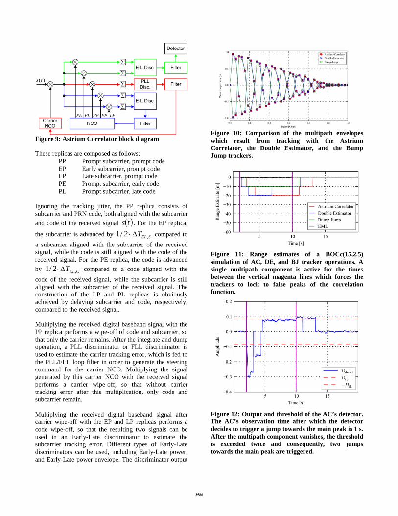
Figure 9: Astrium Correlator block diagram These replicas are composed as follows: PP Prompt subcarrier, prompt code EP Early subcarrier, prompt code LP Late subcarrier, prompt code PE Prompt subcarrier, early code PL Prompt subcarrier, late code Ignoring the tracking jitter, the PP replica consists of subcarrier and PRN code, both aligned with the subcarrier and code of the received signal ( )ts . For the EP replica,
the subcarrier is advanced by SELT ,2/1 ∆⋅ compared to a subcarrier aligned with the subcarrier of the received signal, while the code is still aligned with the code of the received signal. For the PE replica, the code is advanced by CELT ,2/1 ∆⋅ compared to a code aligned with the code of the received signal, while the subcarrier is still aligned with the subcarrier of the received signal. The construction of the LP and PL replicas is obviously achieved by delaying subcarrier and code, respectively, compared to the received signal. Multiplying the received digital baseband signal with the PP replica performs a wipe-off of code and subcarrier, so that only the carrier remains. After the integrate and dump operation, a PLL discriminator or FLL discriminator is used to estimate the carrier tracking error, which is fed to the PLL/FLL loop filter in order to generate the steering command for the carrier NCO. Multiplying the signal generated by this carrier NCO with the received signal performs a carrier wipe-off, so that without carrier tracking error after this multiplication, only code and subcarrier remain. Multiplying the received digital baseband signal after carrier wipe-off with the EP and LP replicas performs a code wipe-off, so that the resulting two signals can be used in an Early-Late discriminator to estimate the subcarrier tracking error. Different types of Early-Late discriminators can be used, including Early-Late power, and Early-Late power envelope. The discriminator output
Figure 10: Comparison of the multipath envelopes which result from tracking with the Astrium Correlator, the Double Estimator, and the Bump Jump trackers.
Figure 11: Range estimates of a BOCc(15,2.5) simulation of AC, DE, and BJ tracker operations. A single multipath component is active for the times between the vertical magenta lines which forces the trackers to lock to false peaks of the correlation function.
Figure 12: Output and threshold of the AC’s detector. The AC’s observation time after which the detector decides to trigger a jump towards the main peak is 1 s. After the multipath component vanishes, the threshold is exceeded twice and consequently, two jumps towards the main peak are triggered.

is fed to a loop filter, which generates the steering command for the NCO generating the five replicas described previously, hereby closing the subcarrier loop. Multiplying the received digital baseband signal after carrier wipe-off with the PE and PL replicas performs a subcarrier wipe-off, so that the resulting two signals can be fed in an Early-Late discriminator of any type. The output of this discriminator is lowpass filtered, fed to a detector, and compared to a threshold. The threshold corresponds to the value of the discriminator if the tracker locks to the first side peaks. Given that the subcarrier tracking is locked on the main peak, the signal arriving at the detector is zero-mean. Given that a side peak is tracked, the mean of the signal arriving at the detector significantly exceeds the threshold and its sign indicates whether the false lock is to a side peak left or right from the main peak. This allows identifying the false lock, and a correction can be performed so that the subcarrier loop transfers lock from the side peak to the neighboring peak towards the main peak, until a zero mean detector input signal results, indicating the desired lock to the main peak. The proposed tracking algorithm is similar to the Double Estimator (DE) [6] in the sense that it also uses five signal replicas. Yet, the difference is that the Astrium Correlator ties the shifts of subcarrier and PRN code signals together and tracks both jointly with a single SLL, whereas the Double Estimator tracks both components independently with two separate loops. Hence, the Double Estimator requires one loop more, namely the DLL. Moreover, the subcarrier and PRN code signal components can never diverge from each other because they are not transmitted separately but the multiplication of both components. The Astrium Correlator uses this a-priory knowledge. If the Astrium Correlator is compared to the Bump Jump (BJ) and Double Estimator trackers, it shows a similar performance in the presence of noise, continuous-wave interference, chirp interference, asymmetric filtering, and multipath [7]. As an example Figure 10 shows the multipath envelope of a BOCc(15,2.5) signal as computed by the AC, DE, and BJ trackers. The Astrium Correlator’s detector for locks to false peaks has two degrees of freedom: the time constant of the low pass filter that performs smoothing of the detector output and the duration of how long the detector threshold must be exceeded until a jump towards the main peak is triggered. Figure 11 shows the range estimates resulting from a BOCc(15,2.5) simulation of AC, DE, and BJ tracker operations, where a single multipath component was active between 2 s and 10 s. This component forces these three trackers to lock to a side peak. The Early-Minus Late (EML) tracker does not notice the additional signal component. Figure 12 shows the output of the AC’s
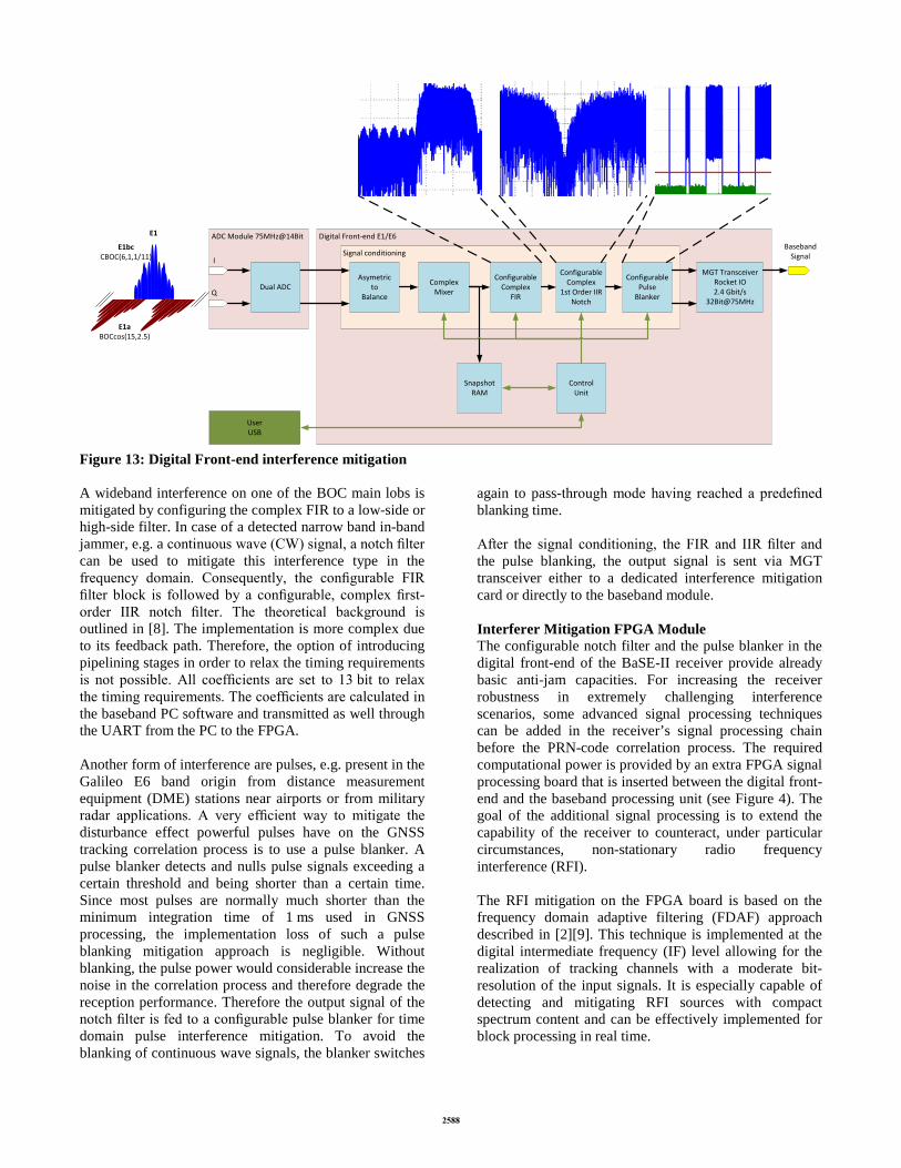
detector Ddetect together with the upper and lower thresholds Dth and –Dth, respectively. The actual time to detect locks to false peaks and the required duration to recover from them can be tuned using the two mentioned parameters. The novel Astrium Correlator proves to be an adequate technique to track high-rate, multi-peaked BOC signals. It shows similar performance under various distortions than comparable tracking methods. INTERFERENCE MITIGATION Beside the interference mitigation technique based on conventional adaptive time domain filtering and blanking, the robustness of the receiver can be furthermore increased by implementing additional advanced signal processing algorithms in the frequency domain. They extend the capability of the receiver to counteract, under particular circumstances, non-stationary radio frequency interference. For BaSE-II a frequency domain adaptive filtering (FDAF) approach was implemented in a dedicated interferer mitigation FPGA module. The utilization of antenna arrays and the associated signal processing techniques in the BaSE receiver enables mitigation of radio frequency interference also in the spatial domain. The mitigation of interfering signals is achieved by controlling the reception pattern of the antenna array and adaptive adjustment according to changing signal conditions. Moreover, the use of adaptive antenna array technology allows distinguishing between authentic and counterfeit GNSS signals in the spatial domain. Interferer Mitigation in the Digital Front-End The digital front-end performs the analog to digital conversion of the complex analog signals received from the RF front-end modules, followed by a first signal conditioning, the interference mitigation modules, and the high speed multi gigabit transceiver (MGT) interface for the transmission of the raw samples. The digital front-end block diagram is shown in Figure 13. In order to detect possible interferers the incoming signals have to be analyzed. For this reason, a snapshot memory is provided after the mixing phase allowing approximate one millisecond (in this case 75000 samples) of raw data collection. Since the interference analysis on the snapshot data is performed e.g. only at 0.1 Hz rate, a UART interface is sufficient to be used for the transmission of the snapshot to the PC. Different interference characterization methods like Welch PSD estimation are carried out in software to characterize the possible interference signal.
ADC Module 75MHz@14Bit Digital Front-end E1/E6
Signal conditioning
Asymetricto
Balance
ComplexMixer
ConfigurableComplex
FIR
ConfigurableComplex
1st Order IIRNotch
ConfigurablePulse
Blanker
E1bcCBOC(6,1,1/11)
E1aBOCcos(15,2.5)
E1
ControlUnit
SnapshotRAM
UserUSB
Dual ADC
I
Q
MGT TransceiverRocket IO2.4 Gbit/s
32Bit@75MHz
Baseband Signal
Figure 13: Digital Front-end interference mitigation A wideband interference on one of the BOC main lobs is mitigated by configuring the complex FIR to a low-side or high-side filter. In case of a detected narrow band in-band jammer, e.g. a continuous wave (CW) signal, a notch filter can be used to mitigate this interference type in the frequency domain. Consequently, the configurable FIR filter block is followed by a configurable, complex first-order IIR notch filter. The theoretical background is outlined in [8]. The implementation is more complex due to its feedback path. Therefore, the option of introducing pipelining stages in order to relax the timing requirements is not possible. All coefficients are set to 13 bit to relax the timing requirements. The coefficients are calculated in the baseband PC software and transmitted as well through the UART from the PC to the FPGA. Another form of interference are pulses, e.g. present in the Galileo E6 band origin from distance measurement equipment (DME) stations near airports or from military radar applications. A very efficient way to mitigate the disturbance effect powerful pulses have on the GNSS tracking correlation process is to use a pulse blanker. A pulse blanker detects and nulls pulse signals exceeding a certain threshold and being shorter than a certain time. Since most pulses are normally much shorter than the minimum integration time of 1 ms used in GNSS processing, the implementation loss of such a pulse blanking mitigation approach is negligible. Without blanking, the pulse power would considerable increase the noise in the correlation process and therefore degrade the reception performance. Therefore the output signal of the notch filter is fed to a configurable pulse blanker for time domain pulse interference mitigation. To avoid the blanking of continuous wave signals, the blanker switches
again to pass-through mode having reached a predefined blanking time. After the signal conditioning, the FIR and IIR filter and the pulse blanking, the output signal is sent via MGT transceiver either to a dedicated interference mitigation card or directly to the baseband module. Interferer Mitigation FPGA Module The configurable notch filter and the pulse blanker in the digital front-end of the BaSE-II receiver provide already basic anti-jam capacities. For increasing the receiver robustness in extremely challenging interference scenarios, some advanced signal processing techniques can be added in the receiver’s signal processing chain before the PRN-code correlation process. The required computational power is provided by an extra FPGA signal processing board that is inserted between the digital front-end and the baseband processing unit (see Figure 4). The goal of the additional signal processing is to extend the capability of the receiver to counteract, under particular circumstances, non-stationary radio frequency interference (RFI). The RFI mitigation on the FPGA board is based on the frequency domain adaptive filtering (FDAF) approach described in [2][9]. This technique is implemented at the digital intermediate frequency (IF) level allowing for the realization of tracking channels with a moderate bit-resolution of the input signals. It is especially capable of detecting and mitigating RFI sources with compact spectrum content and can be effectively implemented for block processing in real time.

FDAF technique is based on FFT. The block diagram illustrating the principle of the FDAF algorithm is shown in Figure 14. The principle consists in nulling out those FFT frequency bins which level exceeds a given threshold. The threshold value is set in the way to assure with a certain probability that the nulled-out bins contain the energy of radio frequency interference signal(s).
Figure 14: Block diagram of realization of frequency domain adaptive filtering The interference detection threshold is set based on the thermal noise floor statistics which is usually has to be estimated under interference-free conditions. In the frequency domain, the thermal noise floor is assumed to be constant over the length of a single FFT block. The estimation process delivers a mean value of the noise floor and an associated variance of the estimation. The latter represents a very important factor for the performance of interference detection: the lower the estimation variance, the lower the false alarm probability (PFA) and higher the detection probability (PD). According to [10] fixing the desired PFA, the corresponding threshold ϒ is given by:
−=
FAPN 12ln2σγ
where σ2 is the variance of the FDAF input signal and N is the FFT length that in our case is equal to 1024 samples. Once the threshold ϒ is fixed, the corresponding PD depends on the Probability Density Function (PDF) of the RFI signal magnitude. If the PDF of the interfering signal is known, the PD can be determined by integrating it over the interval [PFA, ∞]; in other case PD shall be determined numerically via Monte-Carlo simulations. One of the major issues when using the FDAF technique is the spectral leakage effect. This effect occurs when the energy of the Fourier components which are not harmonic to the fundamental frequency become spread over the adjacent frequency bins. The leakage effect in FFT reduces drastically the selectivity in frequency and leads to the excision of a wider portion of the spectrum than strictly needed. To overcome this problem the signal being processed by the Fourier transform shall be first multiplied by a scaling window. A rich selection of windowing functions can be found in the literature; here 17 different scaling windows made available by MATLAB R2011a have been used.
The windows have been evaluated in terms of reduction of the leakage effect, or in other words in terms of improvement in the interference mitigation capability. The effect of the windowing functions on the FDAF performance has been simulated by using a sine wave with frequency fi falling between two adjacent harmonics of the fundamental frequency as the test signal. The simulation results are presented in Figure 15 and Figure 16 for a selected subset of 4 out of 17 windowing functions. The selection criterion was the reduction of the leakage effect in frequency bins from 1 to 6 around fi. The single side spectra after windowing and FFT are shown in Figure 15 (‘none’ indicates that no window is used). The sharper the spectrum, the better the FDAF performance, since the interferer power is confined in a smaller portion of the spectrum.
Figure 15: Single-side FFT spectrum of a sine wave signal after windowing Figure 16 shows the attenuation of the sine-wave RFI as a function of the number of FFT bins around the sinus carrier frequency fi considered for excision.
Figure 16: Mitigation capability of a sine wave signal after windowing

The window coefficients can be stored in form of a 5-bits array on the FPGA ROM. More than one windowing function can be stored on the ROM allowing an online selection of the desired window. The time signal at the output of FDAF is obtained via an inverse FFT of the altered spectrum. Two overlapping windowing functions and two FDAF units are needed in order to reduce amplitude distortion caused by each single scaling window (see Figure 17).
Figure 17: Mitigation schema using FDAF plus windowing Interferer Mitigation with Adaptive Antenna Array For achieving the best possible mitigation performance in complex interference scenarios the techniques described above which operate in time and frequency domains can be combined with the processing in spatial domain. The BaSE-II receiver supports this option by making use of the antenna array hardware and associated signal processing software in the digital baseband part. The mitigation of the interfering signals is achieved by adaptive control of the reception pattern of the antenna array and generation of spatial zeros in the corresponding directions. The adaptation of the array reception pattern is based on continuous estimation of the statistics of the
array signals, such as the array covariance matrix xxR̂ . In the signal processing flow of a GNSS receiver there are two options for collecting this statistics: before and after the PRN-code correlation (see Figure 18). In the first case, the useful signals are buried into the noise and the signal statistics is determined either by the thermal noise and/or radio interference. The main focus of the adaptive antenna processing here is on the mitigation of radio frequency interference. This allows using the receiver signal processing blocks which are designed for a nominal GNSS signal dynamic range. Since this range is dominated by the receiver thermal noise, practical fixed-point realizations with low bit widths can be allowed. The signal acquisition, one of the most vulnerable stages of the entire signal processing chain, can benefit from the array gain produced due to the pre-correlation beamforming (see Figure 19). This is achieved by adding the spatial dimension into the acquisition search space and using switched antenna beams each covering a given spatial search bin. The radio interference mitigation before the PRN code correlation is performed with help of the pre-whitening technique based on the eigenvalue decomposition of the
estimated array covariance matrix and an orthogonal projection [11]:
[ ].ˆˆ
ˆˆ
000ˆˆˆ
H
H2
HUUP xPy
UUI
ΛUUR
nnII
n
IMn
InIxx
, ≈=
+
=
⊥⊥
σ
After the PRN code correlation, the estimated statistics is determined by the satellite signal being tracked and, if present, multipath echoes. The antenna pattern is optimized here for enhancing the reception of the GNSS signal being tracked in terms of signal-to-noise-plus-interference ratio (SNIR). The following approaches can be used to achieve this goal: • Eigenbeamforming:
{ }xxP Rw ˆ= , where { }xxP R̂ denotes the principal eigenvector of matrix xxR̂ .
• Minimum mean squared error (MMSE) beamforming:
−=
2Hminarg ywww
r .
• Deterministic beam-steering into a direction of the GNSS signal, ( )ϕθ , , given by the scan θ and azimuth ϕ angles in the antenna local Cartesian coordinate system:
( )ϕθ ,a=w where ( )ϕθ ,a stands for the array steering vector consisting of the complex values of the reception patterns of the array elements in the direction ( )ϕθ , .
Figure 18: Adaptive antenna processing in BaSE receiver prototype
Figure 19: Use of beamforming in signal acquisition stage

Detection and Mitigation of Spoofing / Meaconing The use of adaptive antenna array technology allows for distinguishing between the authentic and counterfeit GNSS signals in the spatial domain. The detection of the spoofed GNSS signals is based on measuring the true directions of arrival (DOAs) of the incoming signal by using the corresponding array processing algorithms. The estimated DOAs of the authentic GNSS signals should be consistent with the geometry of the satellites constellation observed from the user location. In contrast to that, the directions of arrival of the spoofing signals, all of them or at least a subset, should point to a single source. This property is used to detect the event of the spoofing/meaconing attack and identify the direction to the spoofing source. The beamforming control algorithm utilizes this direction for generating there a spatial null. In this way the effect of the spoofing can be almost completely eliminated. For more details on this technique and its performance please see [12]. CONCLUSION The hardware architecture of a robust and experimental Galileo PRS receiver with a miniaturized 2x2 dual-band array antenna developed within the BaSE-II project was presented. To keep the demonstrator unclassified, pseudo-PRS processing was implemented. A novel BOC tracking method that fully exploits the subcarrier accuracy was described and compared to the previously chosen alternatives. The implemented interference mitigation methods in time, frequency and spatial domain increase the robustness against radio frequency interference considerably. Finally, using the array’s direction of arrival estimation for detecting spoofing and meaconing completes the interference mitigation strategy of the BaSE-II demonstrator. ACKNOWLEDGMENTS The BaSE consortium would like to thank the Bavarian Ministry of Economic Affairs for their co-funding and support. REFERENCES [1] GIOVE-A+B Public SIS ICD (2008), GIOVE-A+B (#102) Navigation Signal-in-Space Interface Control Document (GIOVE-A+B Public SIS ICD) Issue 1, tech. rep., ESA ESTEC, Aug. 2008.
[2] A. Rügamer, I. Suberviola, F. Förster, G. Rohmer, A. Konovaltsev, N. Basta, M. Meurer, J. Wendel, M. Kaindl, S. Baumann, “A Bavarian Initiative Towards a Robust Galileo PRS Receiver,” in Proceedings of the ION GNSS 2011, Portland, OR, September 2011, pp. 3668-3678
[3] Spirent Support Documentation: http://ekb.spirentcom.com/index?page=content&id=FAQ13323
[4] P. Neumaier, F. Garzia, P. Sommer, A. Rügamer, G. Rohmer, J. Wendel, F.M. Schubert, "Experimental BOC Tracking Hardware Platform," Proceedings of the ION ITM 2014, San Diego, CA, January 2014, pp. 853-867.
[5] I. Suberviola, S. Köhler, J. Mendizabal, G. Rohmer, "Doppler Search as Pre-acquisition Step," Proceedings of ION GNSS 2009, Savannah, GA, September 2009, pp. 2646-2652.
[6] P. Blunt, Advanced Global Navigation Satellite System Receiver Design. PhD Thesis, 2007
[7] F. M. Schubert, J. Wendel, M. Söllner, M. Kaindl, and R. Kohl, “The Astrium Correlator: Unambiguous Tracking of High-Rate BOC Signals,” in Proceedings of the IEEE/ION Positioning, Location, and Navigation Symposium (PLANS) 2014, Monterey, CA, USA, 2014.
[8] J. Wendel, F. Schubert, A. Rügamer, P. Neumaier, F. Garzia, P. Sommer, G. Rohmer, M. Sgammini, A. Konovaltsev, M. Meurer, and S. Baumann, “BaSE: Development of a Galileo PRS Receiver,” in Proceedings of the 6th European Workshop on GNSS Signals and Signal Processing, Munich, Germany, 2013
[9] G.X. Gao et al., “DME/TACAN interference mitigation for GNSS: algorithms and flight test results”, GPS Solutions, Nov. 2012.
[10] J Steven M. Kay, “Fundamentals of statistical signal processing, Volume II, Detection Theory“, 1998, pp.279-283.
[11] M. Sgammini, F. Antreich, L. Kurz, M. Meurer, and T. G. Noll, “Blind Adaptive Beamformer Based on Orthogonal Projections for GNSS,” in Proceedings of ION GNSS 2012, Sept. 2012, Nashville, TN, USA.
[12] A. Konovaltsev, M. Cuntz, C. Haettich, and M. Meurer, “Autonomous Spoofing Detection and Mitigation in a GNSS Receiver with an Adaptive Antenna Array,” in Proc. ION GNSS+ 2013, Nashville, TN, USA.