Base Designs Lab Setup for Validated Reference Design.pdf
25
Base Designs Lab Setup for Validated Reference Designs Version 2
Transcript of Base Designs Lab Setup for Validated Reference Design.pdf
Base Designs Lab Setup for Validated Reference DesignsVersion 2
Base Designs Lab Setup for Validated Reference Designs Validated Reference Design
Copyright© 2012 Aruba Networks, Inc. AirWave®, Aruba Networks®, Aruba Mobility Management System®, Bluescanner, For Wireless That Works®, Mobile Edge Architecture®, People Move. Networks Must Follow®, RFprotect®, The All Wireless Workplace Is Now Open For Business, Green Island, and The Mobile Edge Company® are trademarks of Aruba Networks, Inc. All rights reserved. Aruba Networks reserves the right to change, modify, transfer, or otherwise revise this publication and the product specifications without notice. While Aruba uses commercially reasonable efforts to ensure the accuracy of the specifications contained in this document, Aruba will assume no responsibility for any errors or omissions.
Open Source CodeCertain Aruba products include Open Source software code developed by third parties, including software code subject to the GNU General Public License (“GPL”), GNU Lesser General Public License (“LGPL”), or other Open Source Licenses. The Open Source code used can be found at this site:
http://www.arubanetworks.com/open_source
Legal NoticeARUBA DISCLAIMS ANY AND ALL OTHER REPRESENTATIONS AND WARRANTIES, WEATHER EXPRESS, IMPLIED, OR STATUTORY, INCLUDING WARRANTIES OF MERCHANTABILITY, FITNESS FOR A PARTICULAR PURPOSE, TITLE, NONINFRINGEMENT, ACCURACY AND QUET ENJOYMENT. IN NO EVENT SHALL THE AGGREGATE LIABILITY OF ARUBA EXCEED THE AMOUNTS ACUTALLY PAID TO ARUBA UNDER ANY APPLICABLE WRITTEN AGREEMENT OR FOR ARUBA PRODUCTS OR SERVICES PURSHASED DIRECTLY FROM ARUBA, WHICHEVER IS LESS.
Warning and DisclaimerThis guide is designed to provide information about wireless networking, which includes Aruba Network products. Though Aruba uses commercially reasonable efforts to ensure the accuracy of the specifications contained in this document, this guide and the information in it is provided on an “as is” basis. Aruba assumes no liability or responsibility for any errors or omissions.
ARUBA DISCLAIMS ANY AND ALL OTHER REPRESENTATIONS AND WARRANTIES, WHETHER EXPRESSED, IMPLIED, OR STATUTORY, INCLUDING WARRANTIES OF MERCHANTABILITY, FITNESS FOR A PARTICULAR PURPOSE, TITLE, NONINFRINGEMENT, ACCURACY, AND QUIET ENJOYMENT. IN NO EVENT SHALL THE AGGREGATE LIABILITY OF ARUBA EXCEED THE AMOUNTS ACTUALLY PAID TO ARUBA UNDER ANY APPLICABLE WRITTEN AGREEMENT OR FOR ARUBA PRODUCTS OR SERVICES PURCHASED DIRECTLY FROM ARUBA, WHICHEVER IS LESS.
Aruba Networks reserves the right to change, modify, transfer, or otherwise revise this publication and the product specifications without notice.
www.arubanetworks.com
1344 Crossman AvenueSunnyvale, California 94089
Phone: 408.227.4500Fax 408.227.4550
Aruba Networks, Inc. 2
Aruba Networks, Inc. Table of Contents | 3
Base Designs Lab Setup for Validated Reference Designs Validated Reference Design
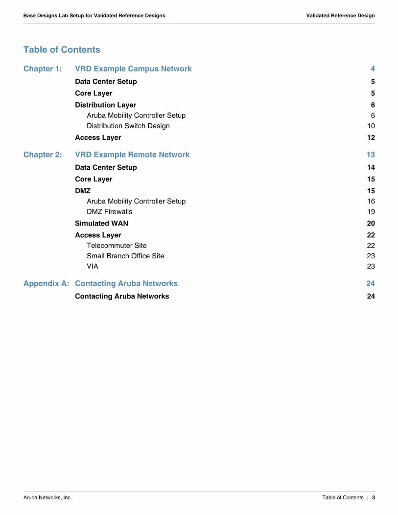
Table of Contents
Chapter 1: VRD Example Campus Network 4Data Center Setup 5Core Layer 5Distribution Layer 6
Aruba Mobility Controller Setup 6Distribution Switch Design 10
Access Layer 12
Chapter 2: VRD Example Remote Network 13Data Center Setup 14Core Layer 15DMZ 15
Aruba Mobility Controller Setup 16DMZ Firewalls 19
Simulated WAN 20Access Layer 22
Telecommuter Site 22Small Branch Office Site 23VIA 23
Appendix A: Contacting Aruba Networks 24Contacting Aruba Networks 24
Base Designs Lab Setup for Validated Reference Designs Validated Reference Design
Chapter 1: VRD Example Campus Network
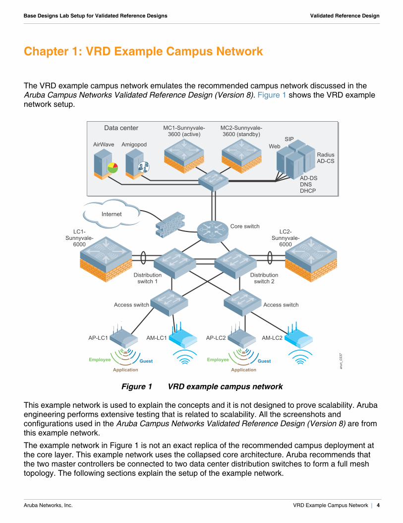
The VRD example campus network emulates the recommended campus network discussed in the Aruba Campus Networks Validated Reference Design (Version 8). Figure 1 shows the VRD example network setup.
Figure 1 VRD example campus network
This example network is used to explain the concepts and it is not designed to prove scalability. Aruba engineering performs extensive testing that is related to scalability. All the screenshots and configurations used in the Aruba Campus Networks Validated Reference Design (Version 8) are from this example network.
The example network in Figure 1 is not an exact replica of the recommended campus deployment at the core layer. This example network uses the collapsed core architecture. Aruba recommends that the two master controllers be connected to two data center distribution switches to form a full mesh topology. The following sections explain the setup of the example network.
arun
_033
7AM-LC1AP-LC1 AM-LC2AP-LC2
GuestEmployee
Application
GuestEmployee
Application
Internet
Data center MC1-Sunnyvale-3600 (active)
MC2-Sunnyvale-3600 (standby)
LC1-Sunnyvale-
6000
LC2-Sunnyvale-
6000
WebSIP
RadiusAD-CS
AD-DSDNSDHCP
Core switch
Distributionswitch 2
Access switchAccess switch
Distributionswitch 1
AirWave Amigopod
Aruba Networks, Inc. VRD Example Campus Network | 4
Base Designs Lab Setup for Validated Reference Designs Validated Reference Design
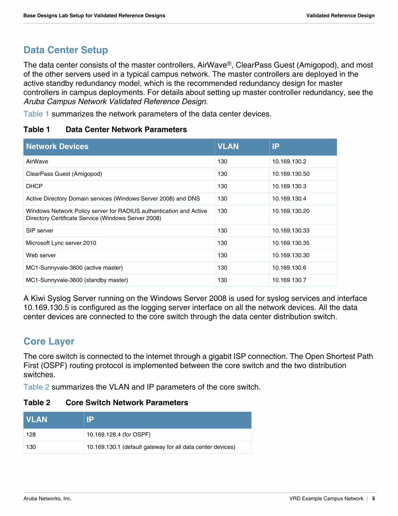
Data Center SetupThe data center consists of the master controllers, AirWave®, ClearPass Guest (Amigopod), and most of the other servers used in a typical campus network. The master controllers are deployed in the active standby redundancy model, which is the recommended redundancy design for master controllers in campus deployments. For details about setting up master controller redundancy, see the Aruba Campus Network Validated Reference Design.
Table 1 summarizes the network parameters of the data center devices.
A Kiwi Syslog Server running on the Windows Server 2008 is used for syslog services and interface 10.169.130.5 is configured as the logging server interface on all the network devices. All the data center devices are connected to the core switch through the data center distribution switch.
Core LayerThe core switch is connected to the internet through a gigabit ISP connection. The Open Shortest Path First (OSPF) routing protocol is implemented between the core switch and the two distribution switches.
Table 2 summarizes the VLAN and IP parameters of the core switch.
Table 1 Data Center Network Parameters
Network Devices VLAN IP
AirWave 130 10.169.130.2
ClearPass Guest (Amigopod) 130 10.169.130.50
DHCP 130 10.169.130.3
Active Directory Domain services (Windows Server 2008) and DNS 130 10.169.130.4
Windows Network Policy server for RADIUS authentication and Active Directory Certificate Service (Windows Server 2008)
130 10.169.130.20
SIP server 130 10.169.130.33
Microsoft Lync server 2010 130 10.169.130.35
Web server 130 10.169.130.30
MC1-Sunnyvale-3600 (active master) 130 10.169.130.6
MC1-Sunnyvale-3600 (standby master) 130 10.169.130.7
Table 2 Core Switch Network Parameters
VLAN IP
128 10.169.128.4 (for OSPF)
130 10.169.130.1 (default gateway for all data center devices)
Aruba Networks, Inc. VRD Example Campus Network | 5
Base Designs Lab Setup for Validated Reference Designs Validated Reference Design
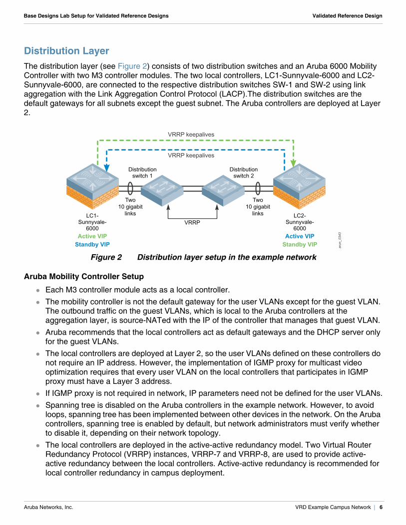
Distribution LayerThe distribution layer (see Figure 2) consists of two distribution switches and an Aruba 6000 Mobility Controller with two M3 controller modules. The two local controllers, LC1-Sunnyvale-6000 and LC2-Sunnyvale-6000, are connected to the respective distribution switches SW-1 and SW-2 using link aggregation with the Link Aggregation Control Protocol (LACP).The distribution switches are the default gateways for all subnets except the guest subnet. The Aruba controllers are deployed at Layer 2.
Figure 2 Distribution layer setup in the example network
Aruba Mobility Controller Setup
Each M3 controller module acts as a local controller. The mobility controller is not the default gateway for the user VLANs except for the guest VLAN.
The outbound traffic on the guest VLANs, which is local to the Aruba controllers at the aggregation layer, is source-NATed with the IP of the controller that manages that guest VLAN.
Aruba recommends that the local controllers act as default gateways and the DHCP server only for the guest VLANs.
The local controllers are deployed at Layer 2, so the user VLANs defined on these controllers do not require an IP address. However, the implementation of IGMP proxy for multicast video optimization requires that every user VLAN on the local controllers that participates in IGMP proxy must have a Layer 3 address.
If IGMP proxy is not required in network, IP parameters need not be defined for the user VLANs. Spanning tree is disabled on the Aruba controllers in the example network. However, to avoid
loops, spanning tree has been implemented between other devices in the network. On the Aruba controllers, spanning tree is enabled by default, but network administrators must verify whether to disable it, depending on their network topology.
The local controllers are deployed in the active-active redundancy model. Two Virtual Router Redundancy Protocol (VRRP) instances, VRRP-7 and VRRP-8, are used to provide active-active redundancy between the local controllers. Active-active redundancy is recommended for local controller redundancy in campus deployment.
arun
_034
3
VRRP keepalives
VRRP keepalives
Active VIPStandby VIP
Active VIPStandby VIP
LC1-Sunnyvale-
6000
LC2-Sunnyvale-
6000
Distributionswitch 2
Two10 gigabit
links
Two10 gigabit
linksVRRP
Distributionswitch 1
Aruba Networks, Inc. VRD Example Campus Network | 6
Base Designs Lab Setup for Validated Reference Designs Validated Reference Design
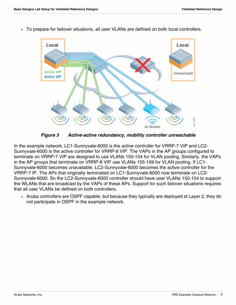
To prepare for failover situations, all user VLANs are defined on both local controllers.
Figure 3 Active-active redundancy, mobility controller unreachable
In the example network, LC1-Sunnyvale-6000 is the active controller for VRRP-7 VIP and LC2-Sunnyvale-6000 is the active controller for VRRP-8 VIP. The VAPs in the AP groups configured to terminate on VRRP-7 VIP are designed to use VLANs 150-154 for VLAN pooling. Similarly, the VAPs in the AP groups that terminate on VRRP-8 VIP use VLANs 155-159 for VLAN pooling. If LC1-Sunnyvale-6000 becomes unavailable, LC2-Sunnyvale-6000 becomes the active controller for the VRRP-7 IP. The APs that originally terminated on LC1-Sunnyvale-6000 now terminate on LC2-Sunnyvale-6000. So the LC2-Sunnyvale-6000 controller should have user VLANs 150-154 to support the WLANs that are broadcast by the VAPs of these APs. Support for such failover situations requires that all user VLANs be defined on both controllers.
Aruba controllers are OSPF capable, but because they typically are deployed at Layer 2, they do not participate in OSPF in the example network.
arun_045
arun
_026
5
Air Monitor
Local
Active VIPActive VIP
Local
Unreachable
Aruba Networks, Inc. VRD Example Campus Network | 7
Base Designs Lab Setup for Validated Reference Designs Validated Reference Design
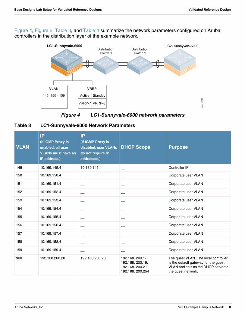
Figure 4, Figure 5, Table 3, and Table 4 summarize the network parameters configured on Aruba controllers in the distribution layer of the example network.
Figure 4 LC1-Sunnyvale-6000 network parameters
Table 3 LC1-Sunnyvale-6000 Network Parameters
VLAN
IP (If IGMP Proxy is enabled, all user VLANs must have an IP address.)
IP (If IGMP Proxy is disabled, user VLANs do not require IP addresses.)
DHCP Scope Purpose
145 10.169.145.4 10.169.145.4 __ Controller IP
150 10.169.150.4 __ __ Corporate user VLAN
151 10.169.151.4 __ __ Corporate user VLAN
152 10.169.152.4 __ __ Corporate user VLAN
153 10.169.153.4 __ __ Corporate user VLAN
154 10.169.154.4 __ __ Corporate user VLAN
155 10.169.155.4 __ __ Corporate user VLAN
156 10.169.156.4 __ __ Corporate user VLAN
157 10.169.157.4 __ __ Corporate user VLAN
158 10.169.158.4 __ __ Corporate user VLAN
159 10.169.159.4 __ __ Corporate user VLAN
900 192.168.200.20 192.168.200.20 192.168. 200.1-192.168. 200.19, 192.168. 200.21 -192.168. 200.254
The guest VLAN. The local controller is the default gateway for the guest VLAN and acts as the DHCP server to the guest network.
arun
_036
8
Distributionswitch 2
Distributionswitch 1
Active
VRRP-7
Standby
VRRP-8
VLAN
145, 150 - 159
VRRP
LC1-Sunnyvale-6000 LC2- Sunnyvale-6000
Aruba Networks, Inc. VRD Example Campus Network | 8
Base Designs Lab Setup for Validated Reference Designs Validated Reference Design
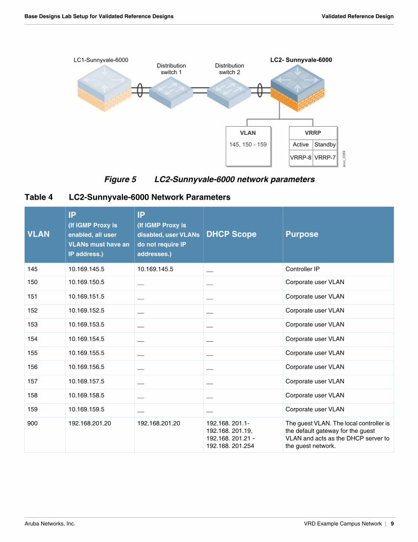
Figure 5 LC2-Sunnyvale-6000 network parameters
Table 4 LC2-Sunnyvale-6000 Network Parameters
VLAN
IP (If IGMP Proxy is enabled, all user VLANs must have an IP address.)
IP (If IGMP Proxy is disabled, user VLANs do not require IP addresses.)
DHCP Scope Purpose
145 10.169.145.5 10.169.145.5 __ Controller IP
150 10.169.150.5 __ __ Corporate user VLAN
151 10.169.151.5 __ __ Corporate user VLAN
152 10.169.152.5 __ __ Corporate user VLAN
153 10.169.153.5 __ __ Corporate user VLAN
154 10.169.154.5 __ __ Corporate user VLAN
155 10.169.155.5 __ __ Corporate user VLAN
156 10.169.156.5 __ __ Corporate user VLAN
157 10.169.157.5 __ __ Corporate user VLAN
158 10.169.158.5 __ __ Corporate user VLAN
159 10.169.159.5 __ __ Corporate user VLAN
900 192.168.201.20 192.168.201.20 192.168. 201.1-192.168. 201.19, 192.168. 201.21 -192.168. 201.254
The guest VLAN. The local controller is the default gateway for the guest VLAN and acts as the DHCP server to the guest network.
arun
_036
9
LC1-Sunnyvale-6000 LC2- Sunnyvale-6000Distribution
switch 2Distribution
switch 1
Active
VRRP-8
Standby
VRRP-7
VLAN
145, 150 - 159
VRRP
Aruba Networks, Inc. VRD Example Campus Network | 9
Base Designs Lab Setup for Validated Reference Designs Validated Reference Design
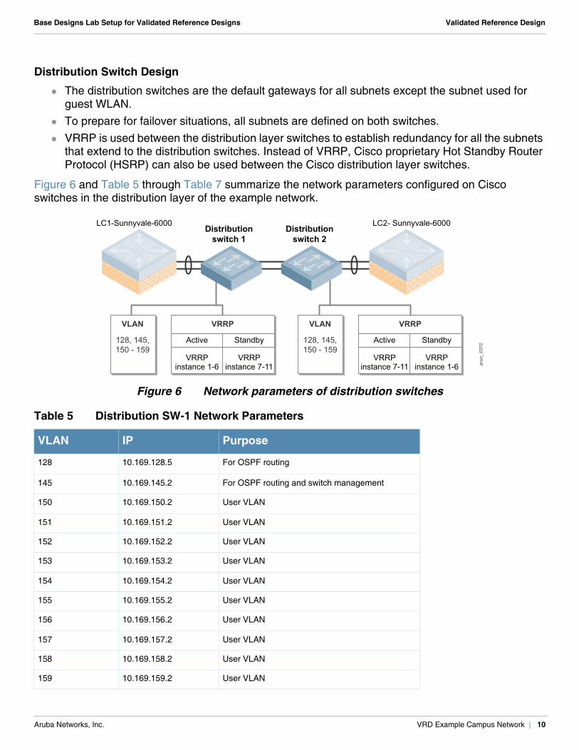
Distribution Switch Design
The distribution switches are the default gateways for all subnets except the subnet used for guest WLAN.
To prepare for failover situations, all subnets are defined on both switches. VRRP is used between the distribution layer switches to establish redundancy for all the subnets
that extend to the distribution switches. Instead of VRRP, Cisco proprietary Hot Standby Router Protocol (HSRP) can also be used between the Cisco distribution layer switches.
Figure 6 and Table 5 through Table 7 summarize the network parameters configured on Cisco switches in the distribution layer of the example network.
Figure 6 Network parameters of distribution switches
Table 5 Distribution SW-1 Network Parameters
VLAN IP Purpose
128 10.169.128.5 For OSPF routing
145 10.169.145.2 For OSPF routing and switch management
150 10.169.150.2 User VLAN
151 10.169.151.2 User VLAN
152 10.169.152.2 User VLAN
153 10.169.153.2 User VLAN
154 10.169.154.2 User VLAN
155 10.169.155.2 User VLAN
156 10.169.156.2 User VLAN
157 10.169.157.2 User VLAN
158 10.169.158.2 User VLAN
159 10.169.159.2 User VLAN
arun
_037
0
LC1-Sunnyvale-6000 LC2- Sunnyvale-6000Distribution
switch 2Distribution
switch 1
Active
VRRPinstance 1-6
Standby
VRRPinstance 7-11
VLAN
128, 145,150 - 159
VRRP
Active
VRRPinstance 7-11
Standby
VRRPinstance 1-6
VRRPVLAN
128, 145,150 - 159
Aruba Networks, Inc. VRD Example Campus Network | 10
Base Designs Lab Setup for Validated Reference Designs Validated Reference Design
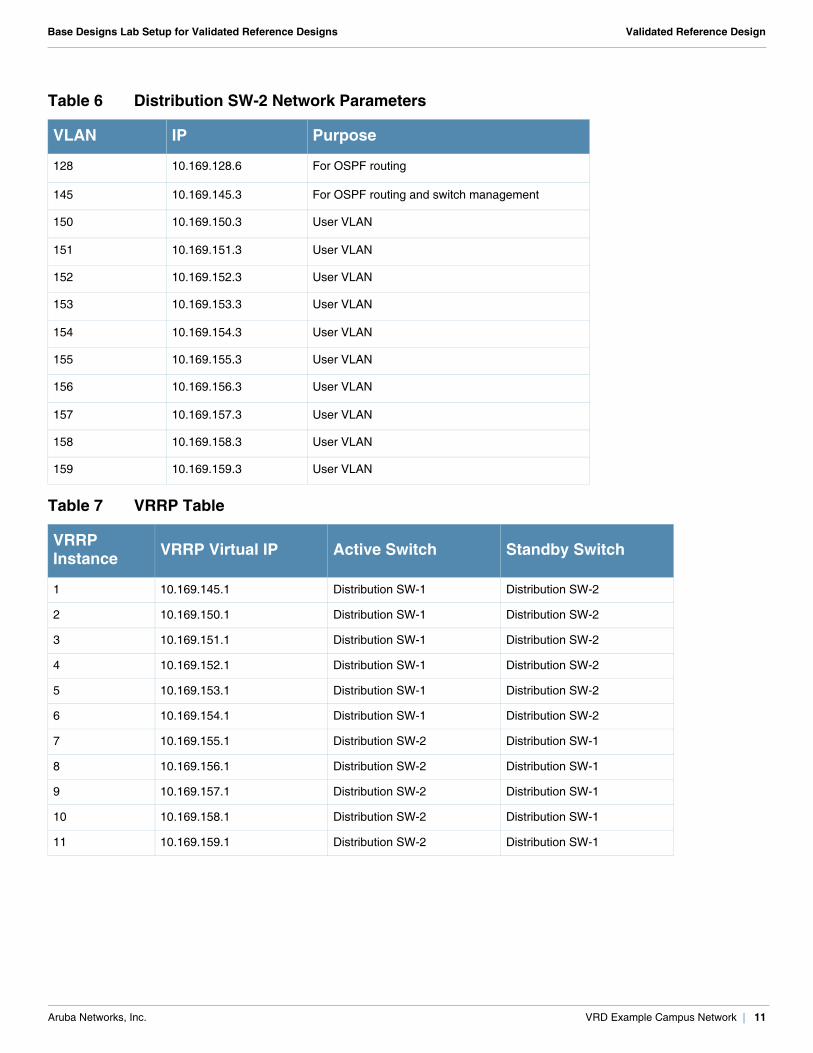
Table 6 Distribution SW-2 Network Parameters
VLAN IP Purpose
128 10.169.128.6 For OSPF routing
145 10.169.145.3 For OSPF routing and switch management
150 10.169.150.3 User VLAN
151 10.169.151.3 User VLAN
152 10.169.152.3 User VLAN
153 10.169.153.3 User VLAN
154 10.169.154.3 User VLAN
155 10.169.155.3 User VLAN
156 10.169.156.3 User VLAN
157 10.169.157.3 User VLAN
158 10.169.158.3 User VLAN
159 10.169.159.3 User VLAN
Table 7 VRRP Table
VRRP Instance VRRP Virtual IP Active Switch Standby Switch
1 10.169.145.1 Distribution SW-1 Distribution SW-2
2 10.169.150.1 Distribution SW-1 Distribution SW-2
3 10.169.151.1 Distribution SW-1 Distribution SW-2
4 10.169.152.1 Distribution SW-1 Distribution SW-2
5 10.169.153.1 Distribution SW-1 Distribution SW-2
6 10.169.154.1 Distribution SW-1 Distribution SW-2
7 10.169.155.1 Distribution SW-2 Distribution SW-1
8 10.169.156.1 Distribution SW-2 Distribution SW-1
9 10.169.157.1 Distribution SW-2 Distribution SW-1
10 10.169.158.1 Distribution SW-2 Distribution SW-1
11 10.169.159.1 Distribution SW-2 Distribution SW-1
Aruba Networks, Inc. VRD Example Campus Network | 11
Base Designs Lab Setup for Validated Reference Designs Validated Reference Design
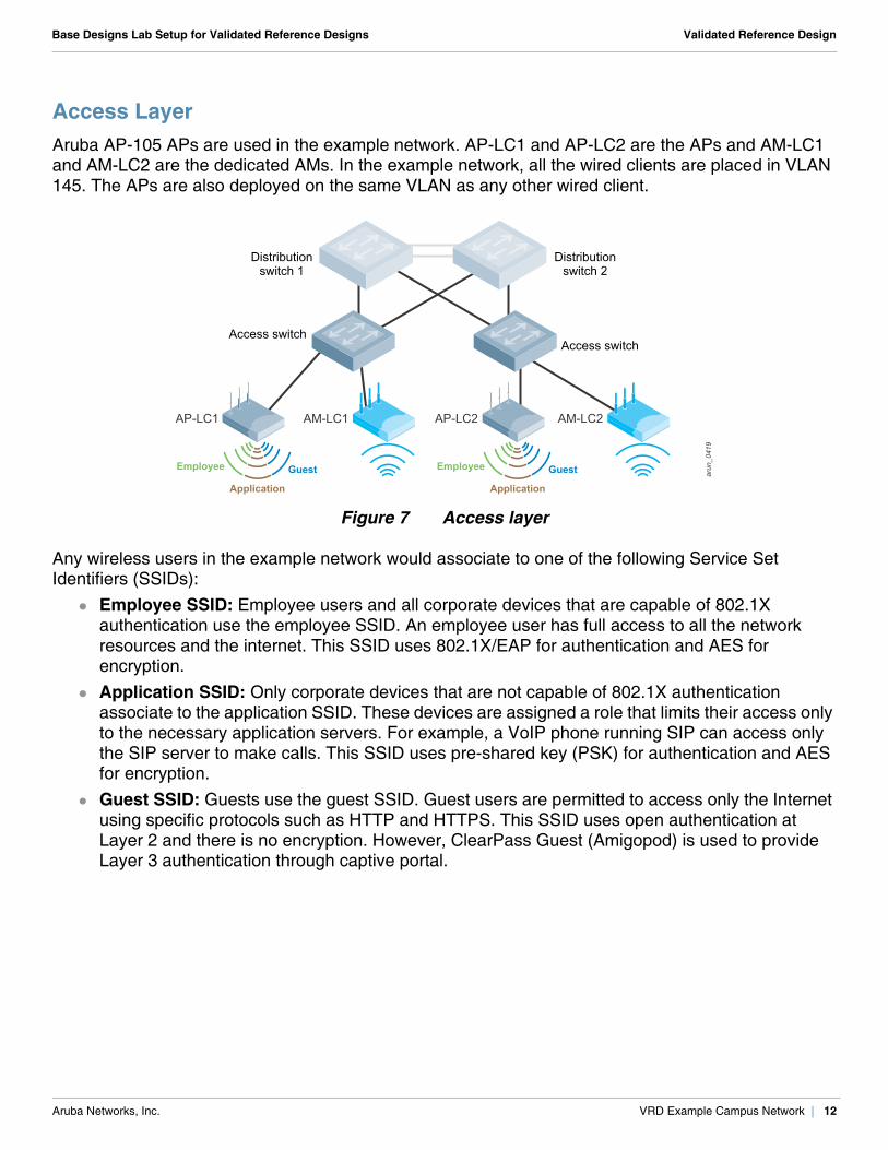
Access LayerAruba AP-105 APs are used in the example network. AP-LC1 and AP-LC2 are the APs and AM-LC1 and AM-LC2 are the dedicated AMs. In the example network, all the wired clients are placed in VLAN 145. The APs are also deployed on the same VLAN as any other wired client.
Figure 7 Access layer
Any wireless users in the example network would associate to one of the following Service Set Identifiers (SSIDs):
Employee SSID: Employee users and all corporate devices that are capable of 802.1X authentication use the employee SSID. An employee user has full access to all the network resources and the internet. This SSID uses 802.1X/EAP for authentication and AES for encryption.
Application SSID: Only corporate devices that are not capable of 802.1X authentication associate to the application SSID. These devices are assigned a role that limits their access only to the necessary application servers. For example, a VoIP phone running SIP can access only the SIP server to make calls. This SSID uses pre-shared key (PSK) for authentication and AES for encryption.
Guest SSID: Guests use the guest SSID. Guest users are permitted to access only the Internet using specific protocols such as HTTP and HTTPS. This SSID uses open authentication at Layer 2 and there is no encryption. However, ClearPass Guest (Amigopod) is used to provide Layer 3 authentication through captive portal.
arun
_041
9
AM-LC1AP-LC1 AM-LC2AP-LC2
GuestEmployee
Application
GuestEmployee
Application
Distributionswitch 2
Access switchAccess switch
Distributionswitch 1
Aruba Networks, Inc. VRD Example Campus Network | 12
Base Designs Lab Setup for Validated Reference Designs Validated Reference Design
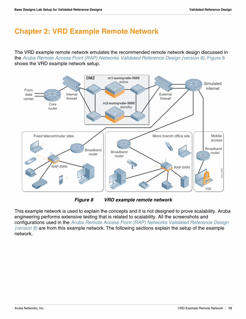
Chapter 2: VRD Example Remote Network
The VRD example remote network emulates the recommended remote network design discussed in the Aruba Remote Access Point (RAP) Networks Validated Reference Design (version 8). Figure 8 shows the VRD example network setup.
Figure 8 VRD example remote network
This example network is used to explain the concepts and it is not designed to prove scalability. Aruba engineering performs extensive testing that is related to scalability. All the screenshots and configurations used in the Aruba Remote Access Point (RAP) Networks Validated Reference Design (version 8) are from this example network. The following sections explain the setup of the example network.
arun
_054
5RAP-5WN
Mobileaccess
Simulatedinternet
Broadband routerBroadband
router
Broadbandrouter
RAP-5WN
Corerouter
Internalfirewall
Externalfirewall
Fixed telecommuter sites Micro branch office site
VIA
Fromdata
center
rc1-sunnyvale-3600active
rc2-sunnyvale-3600 standby
DMZ
Aruba Networks, Inc. VRD Example Remote Network | 13
Base Designs Lab Setup for Validated Reference Designs Validated Reference Design
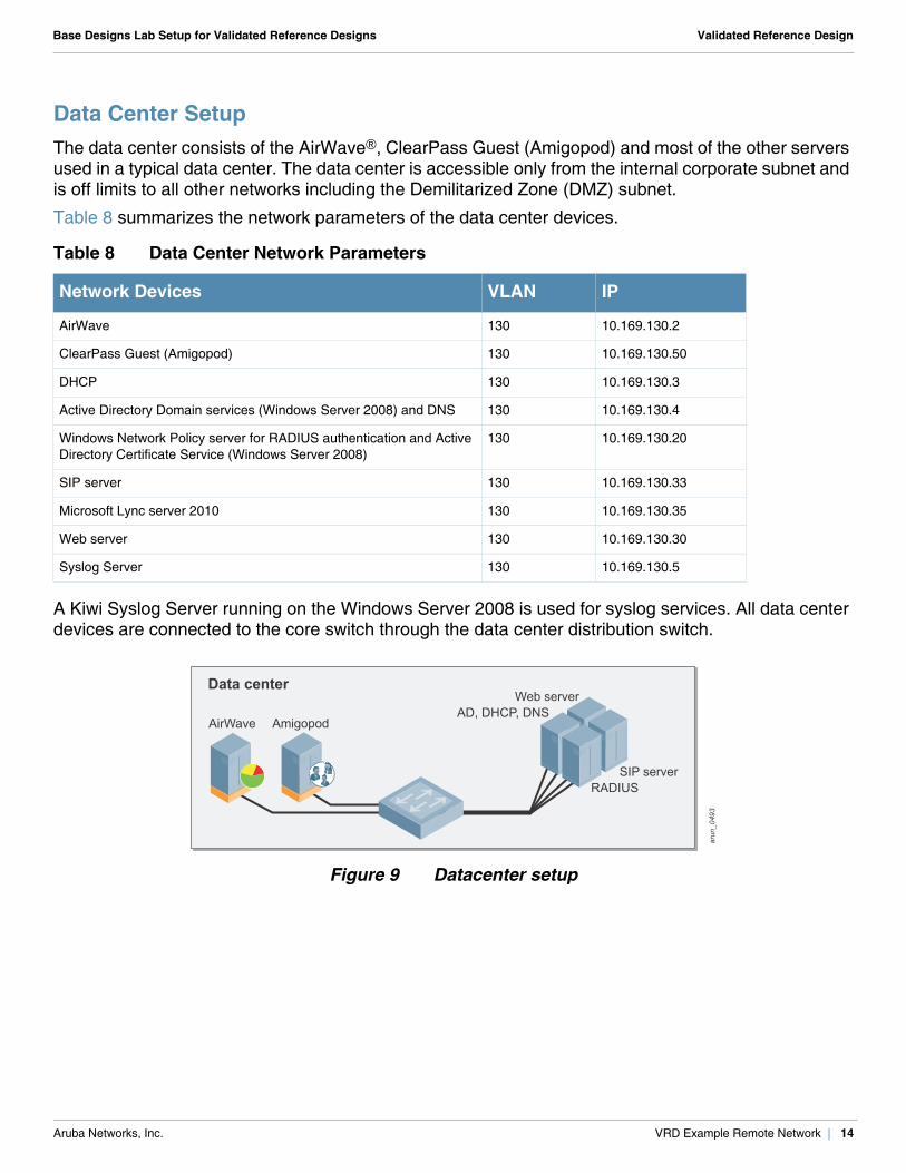
Data Center SetupThe data center consists of the AirWave®, ClearPass Guest (Amigopod) and most of the other servers used in a typical data center. The data center is accessible only from the internal corporate subnet and is off limits to all other networks including the Demilitarized Zone (DMZ) subnet.
Table 8 summarizes the network parameters of the data center devices.
A Kiwi Syslog Server running on the Windows Server 2008 is used for syslog services. All data center devices are connected to the core switch through the data center distribution switch.
Figure 9 Datacenter setup
Table 8 Data Center Network Parameters
Network Devices VLAN IP
AirWave 130 10.169.130.2
ClearPass Guest (Amigopod) 130 10.169.130.50
DHCP 130 10.169.130.3
Active Directory Domain services (Windows Server 2008) and DNS 130 10.169.130.4
Windows Network Policy server for RADIUS authentication and Active Directory Certificate Service (Windows Server 2008)
130 10.169.130.20
SIP server 130 10.169.130.33
Microsoft Lync server 2010 130 10.169.130.35
Web server 130 10.169.130.30
Syslog Server 130 10.169.130.5
arun
_049
3AD, DHCP, DNS
Web server
RADIUSSIP server
Data center
AirWave Amigopod
Aruba Networks, Inc. VRD Example Remote Network | 14
Base Designs Lab Setup for Validated Reference Designs Validated Reference Design
Core LayerThe core switch has access to a gigabit ISP connection through the DMZ. The Open Shortest Path First (OSPF) routing protocol is implemented between the core switch and the two master controllers in the DMZ switches. The core switch also has a default route to reach the Internet and OSPF injects the routes for user VLANs and the VPN address pool used for RAPs and VIA.
Table 9 summarizes the VLAN and IP parameters of the core switch.
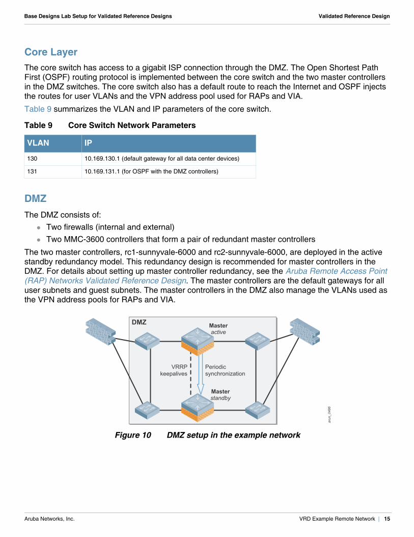
DMZThe DMZ consists of:
Two firewalls (internal and external) Two MMC-3600 controllers that form a pair of redundant master controllers
The two master controllers, rc1-sunnyvale-6000 and rc2-sunnyvale-6000, are deployed in the active standby redundancy model. This redundancy design is recommended for master controllers in the DMZ. For details about setting up master controller redundancy, see the Aruba Remote Access Point (RAP) Networks Validated Reference Design. The master controllers are the default gateways for all user subnets and guest subnets. The master controllers in the DMZ also manage the VLANs used as the VPN address pools for RAPs and VIA.
Figure 10 DMZ setup in the example network
Table 9 Core Switch Network Parameters
VLAN IP
130 10.169.130.1 (default gateway for all data center devices)
131 10.169.131.1 (for OSPF with the DMZ controllers)
arun
_048
6Masteractive
Masterstandby
DMZ
VRRPkeepalives
Periodicsynchronization
Aruba Networks, Inc. VRD Example Remote Network | 15
Base Designs Lab Setup for Validated Reference Designs Validated Reference Design
Aruba Mobility Controller Setup
Each MMC-3600 controller acts as a master controller. The master controllers rc1-sunnyvale-3600 and rc2-sunnyvale-3600 are deployed in active
standby redundancy. The rc1-sunnyvale-3600 controller is the primary master for all VRRP instances (has higher priority for all VRRP instances).
The master controller is the default gateway for all user VLANs and VLANs of guest networks that require captive portal authentication. To prepare for failover situations, all user VLANs are defined on both the controllers and a VRRP instance is configured for each of them.
The master controller acts as the DHCP server only for VLANs of guest networks that require captive portal authentication. These guest VLANs that are local to controller are source-NATed with the IP of the controller that manages them.
The DHCP service information is not shared between the active and backup controller, so the guest subnets on the rc1-sunnyvale-3600 and rc2-sunnyvale-3600 are different. Only the VLAN subnets are different, but the VLAN IDs (VLAN 700) on both controllers are the same. DHCP services are not required for the VPN address pools. The corporate DHCP server is used for the employee VLAN.
Like the VLAN and IP parameters, the VPN pools are not synced from the active controller to the backup controller during database synchronization. The VPN pools are individually configured on both the active and standby master controllers.
OSPF is implemented on the active and standby master controllers to redistribute the user VLANs to the core switch and to learn about the internal LAN network. Only the active controller injects OSPF routes. Routes for a VLAN are injected only if the operation state of that VLAN is up. The operational state of the VLAN used for RAPs and VIA VPN address pool (VLAN 136 and VLAN 138) is manually configured to be in up state.
Spanning tree is disabled on the Aruba controllers in the example network. On the Aruba controllers, spanning tree is enabled by default, but network administrators must verify whether to disable it, depending on their network topology.
Three Virtual Router Redundancy Protocol (VRRP) instances, VRRP-131, VRRP-135, and VRRP-172, are configured between the master controllers deployed in the active-standby redundancy models. For details on these three VRRP instances, see the Aruba Remote Access Point (RAP) Networks Validated Reference Design.
Aruba Networks, Inc. VRD Example Remote Network | 16
Base Designs Lab Setup for Validated Reference Designs Validated Reference Design
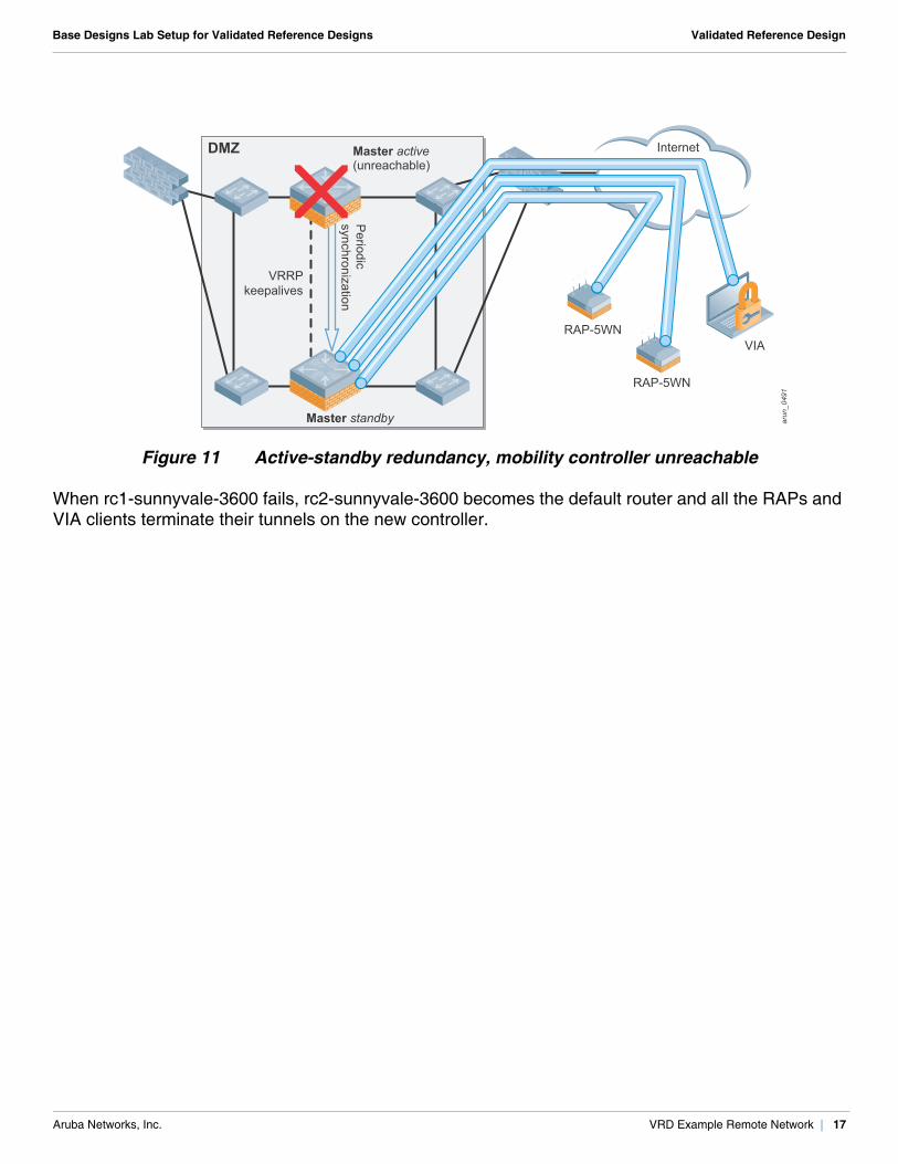
Figure 11 Active-standby redundancy, mobility controller unreachable
When rc1-sunnyvale-3600 fails, rc2-sunnyvale-3600 becomes the default router and all the RAPs and VIA clients terminate their tunnels on the new controller.
arun
_049
1
Master active(unreachable)
Master standby
DMZ
VRRPkeepalives
Periodic
synchronization
Internet
RAP-5WN
RAP-5WNVIA
Aruba Networks, Inc. VRD Example Remote Network | 17
Base Designs Lab Setup for Validated Reference Designs Validated Reference Design
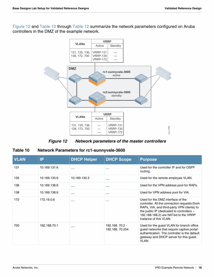
Figure 12 and Table 10 through Table 12 summarize the network parameters configured on Aruba controllers in the DMZ of the example network.
Figure 12 Network parameters of the master controllers
Table 10 Network Parameters for rc1-sunnyvale-3600
VLAN IP DHCP Helper DHCP Scope Purpose
131 10.169.131.6 __ __ Used for the controller IP and for OSPF routing.
135 10.169.135.6 10.169.130.3 __ Used for the remote employee VLAN.
136 10.169.136.6 __ __ Used for the VPN address pool for RAPs.
138 10.169.138.6 __ __ Used for VPN address pool for VIA.
172 172.16.0.6 __ __ Used for the DMZ interface of the controller. All the connection requests (from RAPs, VIA, and third-party VPN clients) to the public IP (dedicated to controllers – 192.168.168.2) are NATed to the VRRP instance of this VLAN.
700 192.168.70.1 __ 192.168. 70.2 -192.168. 70.254
Used for the guest VLAN for branch office guest networks that require captive portal authentication. The controller is the default gateway and DHCP server for this guest VLAN.
arun
_048
9
rc1-sunnyvale-3600active
rc2-sunnyvale-3600standby
DMZ
Active
VRRP-131VRRP-135VRRP-172
Standby
———
VLANs
131, 135, 136,138, 172, 700
VRRP
Standby
VRRP-131VRRP-135VRRP-172
Active
———
VLANs
131, 135, 136,138, 172, 700
VRRP
Aruba Networks, Inc. VRD Example Remote Network | 18
Base Designs Lab Setup for Validated Reference Designs Validated Reference Design
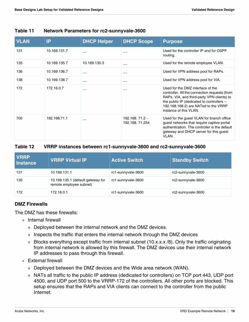
DMZ Firewalls
The DMZ has these firewalls: Internal firewall
Deployed between the internal network and the DMZ devices. Inspects the traffic that enters the internal network through the DMZ devices Blocks everything except traffic from internal subnet (10.x.x.x /8). Only the traffic originating
from internal network is allowed by this firewall. The DMZ devices use their internal network IP addresses to pass through this firewall.
External firewall Deployed between the DMZ devices and the Wide area network (WAN). NATs all traffic to the public IP address (dedicated for controllers) on TCP port 443, UDP port
4500, and UDP port 500 to the VRRP-172 of the controllers. All other ports are blocked. This setup ensures that the RAPs and VIA clients can connect to the controller from the public Internet.
Table 11 Network Parameters for rc2-sunnyvale-3600
VLAN IP DHCP Helper DHCP Scope Purpose
131 10.169.131.7 __ __ Used for the controller IP and for OSPF routing.
135 10.169.135.7 10.169.130.3 __ Used for the remote employee VLAN.
136 10.169.136.7 __ __ Used for VPN address pool for RAPs.
138 10.169.138.7 __ __ Used for VPN address pool for VIA.
172 172.16.0.7 __ __ Used for the DMZ interface of the controller. All the connection requests (from RAPs, VIA, and third-party VPN clients) to the public IP (dedicated to controllers – 192.168.168.2) are NATed to the VRRP instance of this VLAN.
700 192.168.71.1 __ 192.168. 71.2 -192.168. 71.254
Used for the guest VLAN for branch office guest networks that require captive portal authentication. The controller is the default gateway and DHCP server for this guest VLAN.
Table 12 VRRP instances between rc1-sunnyvale-3600 and rc2-sunnyvale-3600
VRRP Instance VRRP Virtual IP Active Switch Standby Switch
131 10.169.131.1 rc1-sunnyvale-3600 rc2-sunnyvale-3600
135 10.169.135.1 (default gateway for remote employee subnet)
rc1-sunnyvale-3600 rc2-sunnyvale-3600
172 172.16.0.1 rc1-sunnyvale-3600 rc2-sunnyvale-3600
Aruba Networks, Inc. VRD Example Remote Network | 19
Base Designs Lab Setup for Validated Reference Designs Validated Reference Design
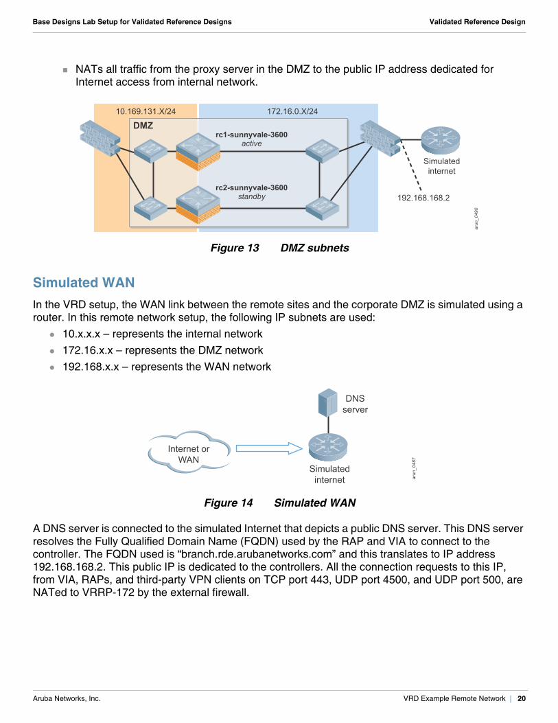
NATs all traffic from the proxy server in the DMZ to the public IP address dedicated for Internet access from internal network.
Figure 13 DMZ subnets
Simulated WANIn the VRD setup, the WAN link between the remote sites and the corporate DMZ is simulated using a router. In this remote network setup, the following IP subnets are used:
10.x.x.x – represents the internal network 172.16.x.x – represents the DMZ network 192.168.x.x – represents the WAN network
Figure 14 Simulated WAN
A DNS server is connected to the simulated Internet that depicts a public DNS server. This DNS server resolves the Fully Qualified Domain Name (FQDN) used by the RAP and VIA to connect to the controller. The FQDN used is “branch.rde.arubanetworks.com” and this translates to IP address 192.168.168.2. This public IP is dedicated to the controllers. All the connection requests to this IP, from VIA, RAPs, and third-party VPN clients on TCP port 443, UDP port 4500, and UDP port 500, are NATed to VRRP-172 by the external firewall.
arun
_049
0
rc1-sunnyvale-3600active
rc2-sunnyvale-3600standby
DMZ
Simulatedinternet
192.168.168.2
10.169.131.X/24 172.16.0.X/24
arun
_048
7
Simulatedinternet
DNSserver
Internet orWAN
Aruba Networks, Inc. VRD Example Remote Network | 20
Base Designs Lab Setup for Validated Reference Designs Validated Reference Design
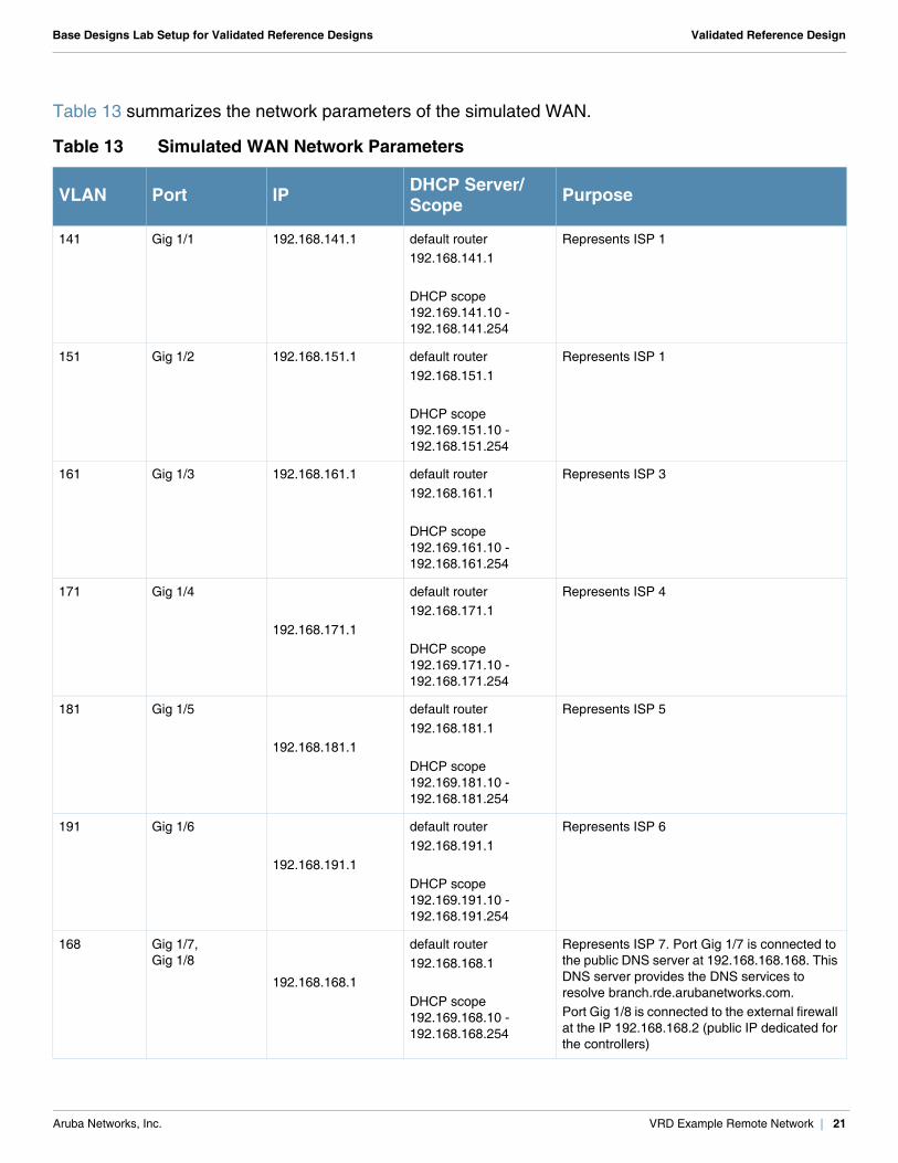
Table 13 summarizes the network parameters of the simulated WAN.
Table 13 Simulated WAN Network Parameters
VLAN Port IP DHCP Server/Scope Purpose
141 Gig 1/1 192.168.141.1 default router 192.168.141.1
DHCP scope 192.169.141.10 - 192.168.141.254
Represents ISP 1
151 Gig 1/2 192.168.151.1 default router 192.168.151.1
DHCP scope 192.169.151.10 - 192.168.151.254
Represents ISP 1
161 Gig 1/3 192.168.161.1 default router 192.168.161.1
DHCP scope 192.169.161.10 - 192.168.161.254
Represents ISP 3
171 Gig 1/4
192.168.171.1
default router 192.168.171.1
DHCP scope 192.169.171.10 - 192.168.171.254
Represents ISP 4
181 Gig 1/5
192.168.181.1
default router 192.168.181.1
DHCP scope 192.169.181.10 - 192.168.181.254
Represents ISP 5
191 Gig 1/6
192.168.191.1
default router 192.168.191.1
DHCP scope 192.169.191.10 - 192.168.191.254
Represents ISP 6
168 Gig 1/7, Gig 1/8
192.168.168.1
default router 192.168.168.1
DHCP scope 192.169.168.10 - 192.168.168.254
Represents ISP 7. Port Gig 1/7 is connected to the public DNS server at 192.168.168.168. This DNS server provides the DNS services to resolve branch.rde.arubanetworks.com. Port Gig 1/8 is connected to the external firewall at the IP 192.168.168.2 (public IP dedicated for the controllers)
Aruba Networks, Inc. VRD Example Remote Network | 21
Base Designs Lab Setup for Validated Reference Designs Validated Reference Design
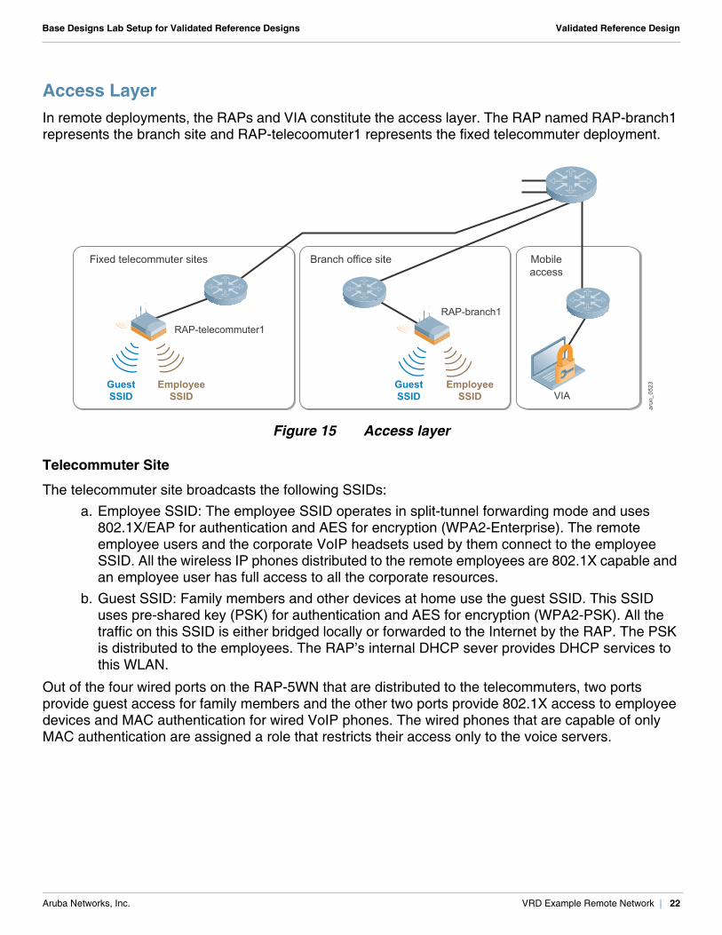
Access LayerIn remote deployments, the RAPs and VIA constitute the access layer. The RAP named RAP-branch1 represents the branch site and RAP-telecoomuter1 represents the fixed telecommuter deployment.
Figure 15 Access layer
Telecommuter Site
The telecommuter site broadcasts the following SSIDs: a. Employee SSID: The employee SSID operates in split-tunnel forwarding mode and uses
802.1X/EAP for authentication and AES for encryption (WPA2-Enterprise). The remote employee users and the corporate VoIP headsets used by them connect to the employee SSID. All the wireless IP phones distributed to the remote employees are 802.1X capable and an employee user has full access to all the corporate resources.
b. Guest SSID: Family members and other devices at home use the guest SSID. This SSID uses pre-shared key (PSK) for authentication and AES for encryption (WPA2-PSK). All the traffic on this SSID is either bridged locally or forwarded to the Internet by the RAP. The PSK is distributed to the employees. The RAP’s internal DHCP sever provides DHCP services to this WLAN.
Out of the four wired ports on the RAP-5WN that are distributed to the telecommuters, two ports provide guest access for family members and the other two ports provide 802.1X access to employee devices and MAC authentication for wired VoIP phones. The wired phones that are capable of only MAC authentication are assigned a role that restricts their access only to the voice servers.
arun
_052
3GuestSSID
EmployeeSSID
GuestSSID
EmployeeSSID
RAP-branch1
Mobileaccess
RAP-telecommuter1
Fixed telecommuter sites Branch office site
VIA
Aruba Networks, Inc. VRD Example Remote Network | 22
Base Designs Lab Setup for Validated Reference Designs Validated Reference Design
Small Branch Office Site
The small branch office site broadcasts the following SSIDs: a. Employee SSID: The employee SSID operates in split-tunnel forwarding mode and uses
802.1X/EAP for authentication and AES for encryption (WPA2-Enterprise). All the employee users and the corporate VoIP headsets in the small branch office connect to the employee SSID. All the wireless VoIP phones in the small branch offices are 802.1X capable and an employee user has full access to all the corporate resources.
b. Guest SSID: Guests use the guest SSID. Guest users are permitted to access only the Internet using specific protocols such as HTTP and HTTPS. This SSID operates in split-tunnel forwarding mode and uses open authentication at Layer 2. Therefore, no over-the-air encryption is used. ClearPass Guest (Amigopod) is used to provide Layer 3 authentication through captive portal. The captive portal user credentials that are tunneled back to the controller are encrypted in an IPsec tunnel.
Out of the four wired ports on the RAP-5WN used in small branch office sites, one port provides guest access with captive portal authentication and the other three ports provide 802.1X access to employee devices and MAC authentication for wired VoIP phones. The wired phones that are capable of only MAC authentication are assigned a role that restricts their access only to the voice servers.
VIA
VIA is used on employee laptops to provide secure corporate access from mobile hotspots.
Aruba Networks, Inc. VRD Example Remote Network | 23
Base Designs Lab Setup for Validated Reference Designs Validated Reference Design
Appendix A: Contacting Aruba Networks
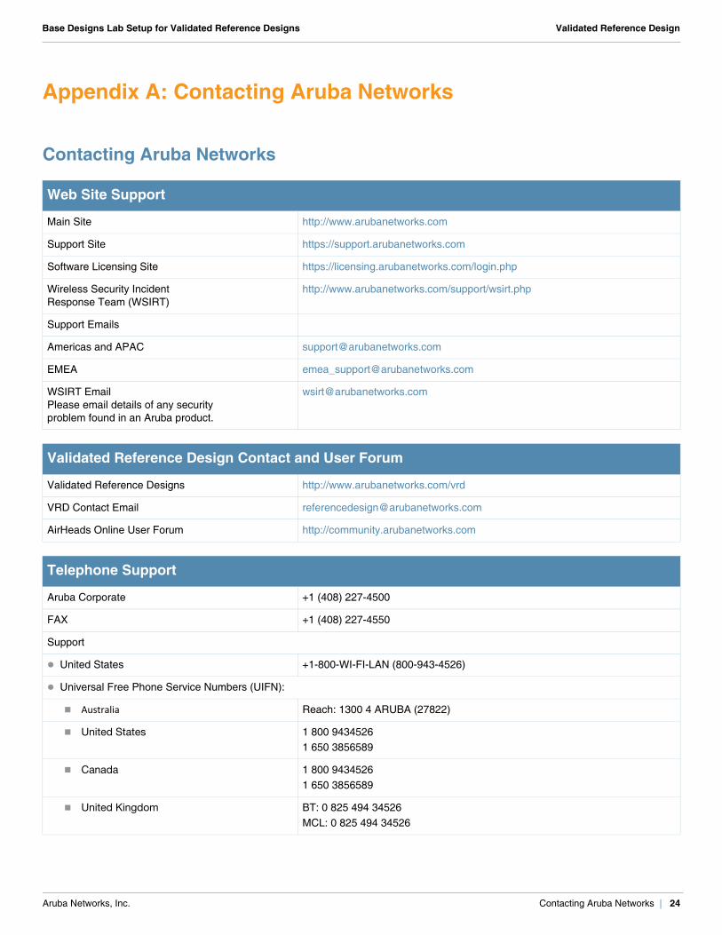
Contacting Aruba Networks
Web Site Support
Main Site http://www.arubanetworks.com
Support Site https://support.arubanetworks.com
Software Licensing Site https://licensing.arubanetworks.com/login.php
Wireless Security IncidentResponse Team (WSIRT)
http://www.arubanetworks.com/support/wsirt.php
Support Emails
Americas and APAC [email protected]
EMEA [email protected]
WSIRT EmailPlease email details of any securityproblem found in an Aruba product.
Validated Reference Design Contact and User Forum
Validated Reference Designs http://www.arubanetworks.com/vrd
VRD Contact Email [email protected]
AirHeads Online User Forum http://community.arubanetworks.com
Telephone Support
Aruba Corporate +1 (408) 227-4500
FAX +1 (408) 227-4550
Support
United States +1-800-WI-FI-LAN (800-943-4526)
Universal Free Phone Service Numbers (UIFN):
Australia Reach: 1300 4 ARUBA (27822)
United States 1 800 94345261 650 3856589
Canada 1 800 94345261 650 3856589
United Kingdom BT: 0 825 494 34526MCL: 0 825 494 34526
Aruba Networks, Inc. Contacting Aruba Networks | 24
Base Designs Lab Setup for Validated Reference Designs Validated Reference Design
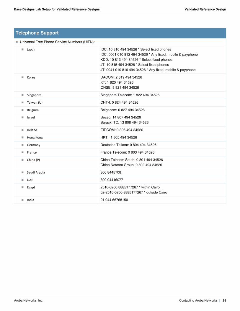
Universal Free Phone Service Numbers (UIFN):
Japan IDC: 10 810 494 34526 * Select fixed phonesIDC: 0061 010 812 494 34526 * Any fixed, mobile & payphoneKDD: 10 813 494 34526 * Select fixed phonesJT: 10 815 494 34526 * Select fixed phonesJT: 0041 010 816 494 34526 * Any fixed, mobile & payphone
Korea DACOM: 2 819 494 34526KT: 1 820 494 34526ONSE: 8 821 494 34526
Singapore Singapore Telecom: 1 822 494 34526
Taiwan (U) CHT-I: 0 824 494 34526
Belgium Belgacom: 0 827 494 34526
Israel Bezeq: 14 807 494 34526Barack ITC: 13 808 494 34526
Ireland EIRCOM: 0 806 494 34526
Hong Kong HKTI: 1 805 494 34526
Germany Deutsche Telkom: 0 804 494 34526
France France Telecom: 0 803 494 34526
China (P) China Telecom South: 0 801 494 34526China Netcom Group: 0 802 494 34526
Saudi Arabia 800 8445708
UAE 800 04416077
Egypt 2510-0200 8885177267 * within Cairo02-2510-0200 8885177267 * outside Cairo
India 91 044 66768150
Telephone Support
Aruba Networks, Inc. Contacting Aruba Networks | 25