
BASCO HEAT EXCHANGERS - firefly...
12
...world leaders in heat transfer technology BASCO TYPE 500 HEAT EXCHANGERS ®
Transcript of BASCO HEAT EXCHANGERS - firefly...

...world leaders in heat transfer technology
BASCOTYPE 500
HEATEXCHANGERS
®
– 2 –
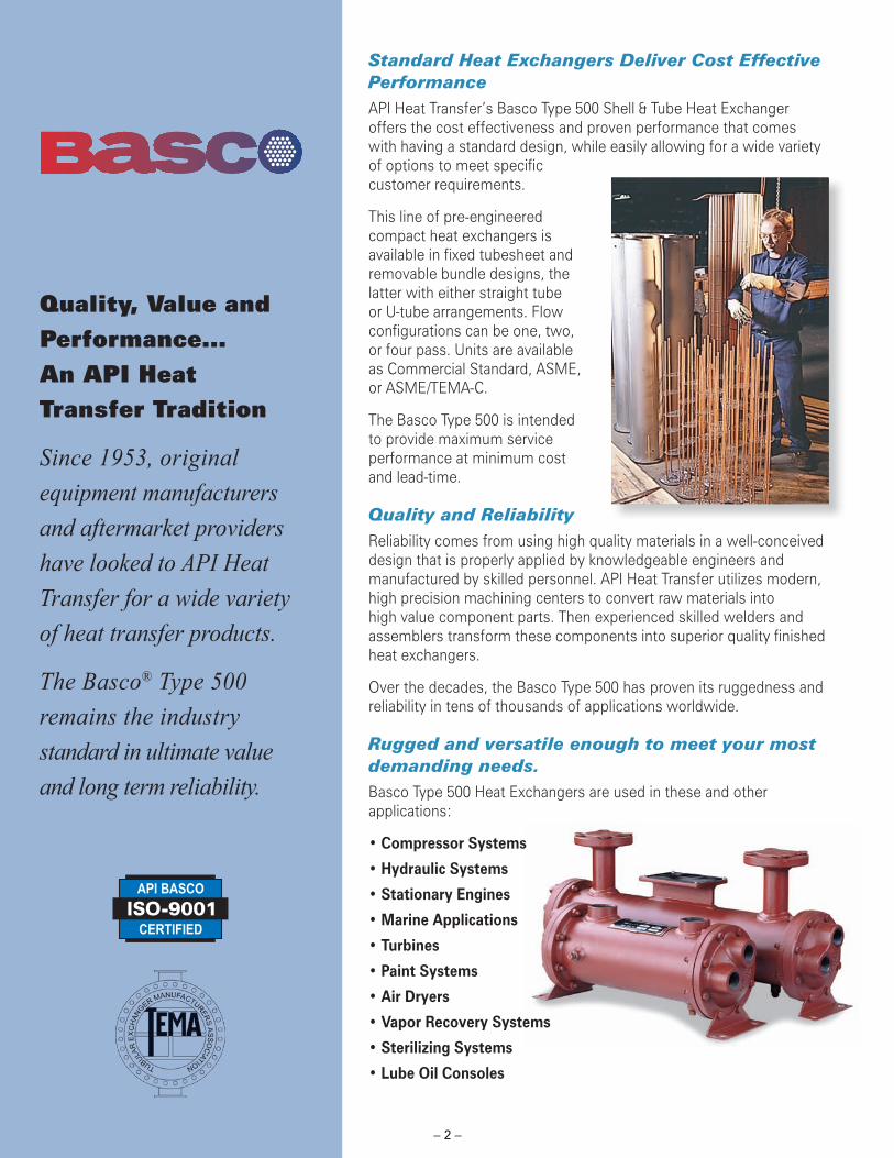
Standard Heat Exchangers Deliver Cost Effective Performance API Heat Transfer’s Basco Type 500 Shell & Tube Heat Exchanger offers the cost effectiveness and proven performance that comes with having a standard design, while easily allowing for a wide variety of options to meet specifi c customer requirements.
This line of pre-engineered compact heat exchangers is available in fi xed tubesheet and removable bundle designs, the latter with either straight tube or U-tube arrangements. Flow confi gurations can be one, two, or four pass. Units are available as Commercial Standard, ASME, or ASME/TEMA-C.
The Basco Type 500 is intended to provide maximum service performance at minimum cost and lead-time.
Quality and ReliabilityReliability comes from using high quality materials in a well-conceived design that is properly applied by knowledgeable engineers and manufactured by skilled personnel. API Heat Transfer utilizes modern, high precision machining centers to convert raw materials into high value component parts. Then experienced skilled welders and assemblers transform these components into superior quality fi nished heat exchangers.
Over the decades, the Basco Type 500 has proven its ruggedness and reliability in tens of thousands of applications worldwide.
Rugged and versatile enough to meet your most demanding needs.Basco Type 500 Heat Exchangers are used in these and other applications:
• Compressor Systems
• Hydraulic Systems
• Stationary Engines
• Marine Applications
• Turbines
• Paint Systems
• Air Dryers
• Vapor Recovery Systems
• Sterilizing Systems
• Lube Oil Consoles
Quality, Value and Performance... An API Heat Transfer Tradition
Since 1953, original equipment manufacturers and aftermarket providers have looked to API Heat Transfer for a wide variety of heat transfer products.
The Basco® Type 500 remains the industry standard in ultimate value and long term reliability.

– 3 –
Manufacturing at a GlanceOur Basco Type 500 is manufactured in two facilities – Buffalo, NY and Suzhou, China – to support our customers on a global basis. Each facility has ISO 9001 certifi cation assuring world-class manufacturing methods and full accountability.
Robotic CNC Machining Center assures precision drilled tubesheets, twenty-four hours a day.
Use of rolled coil tubing supports the fl exibility inherent in DFT manufacturing. Special straightening equipment and unique burr-free cutting process result in superior rolled joints.
MOUNTING BRACKETSHeavy stamped steel brackets are standard and can be rotated and reversed for a variety of mounting needs. Installations other than horizontal with the brackets underneath should be checked for weight. Cradle mounting is available on all models.
TUBESTubes are available in Copper, 90/10 CuNi, Stainless Steel, Admiralty or Titanium. Tubes are roller expanded. Seal welding and grooving available in some cases.
SHELLSRugged shell available in Steel and Stainless Steel. Minimum clearances between shell and baffl es reduce by-pass and maximize heat transfer.
BAFFLESPrecision punched baffl es assure effective circulation by providing minimum clearances between the tubes and tube holes. Baffl e cuts and spacing for each diameter are consistent with best practices.
TUBESHEETSThick Carbon Steel, Stainless Steel or 90/10 CuNi tubesheets are welded to the shell. Holes are precision drilled for proper fi t.
END BONNETSEnd Bonnets are of high quality cast Iron, Bronze or Stainless Steel in 1, 2 or 4-pass configurations. Fabricated heads are available and are standard on TEMA-C models. Zinc anodes to neutralize the effects of galvanic action can be furnished on special order.

– 4 –
Type 500 S Materials
Shell ........................ Welded 304 StainlessTubes ...................... 304 Stainless SteelTubesheets ............. 304 Stainless SteelBonnets .................. Cast 304 StainlessBaffl es .................... 304 Stainless SteelGaskets................... Compressed Fiber
ASME/TEMA-C Materials
Shell ........................ Carbon SteelTubes ...................... Copper, Admiralty, 90/10 CuNi, SSTubesheets ............. Carbon Steel, 90/10, SSBonnets .................. Carbon Steel, Cast Ductile IronBaffl es .................... Carbon Steel, SSGaskets................... Compressed Fiber
Basco Type 500 Heat Exchangers
Type 500 Commercial Standard Models3” – 8” Diameters, Straight and U-Tubes
Type 500 Stainless Steel Models3” – 8” Diameters, Straight and U-Tubes
Type 500 ASME/TEMA-C Models5” – 12” Diameters, Straight and U-Tubes
Type 500 Standard Materials
Shell ........................ Steel Pipe or TubingTubes ...................... Copper, Admiralty or 90/10 CuNiTubesheets ............. Steel, Stainless or 90/10 CuNiBonnets .................. Cast IronBaffl es .................... Carbon SteelGaskets................... Compressed Fiber
Commercial standard model and modifi ed model with special shellside fl anges shown. Several modifi cations are available without adding manufacturing delays.
Model shown is removable tubesheet U-tube with type 304 Stainless Steel tubing. Fixed bundle models also available.
ASME Code models are available from 5” diameter and up. TEMA-C models are available in straight and U-tube designs through 12” diameter.
– 5 –
Common Specifi cations
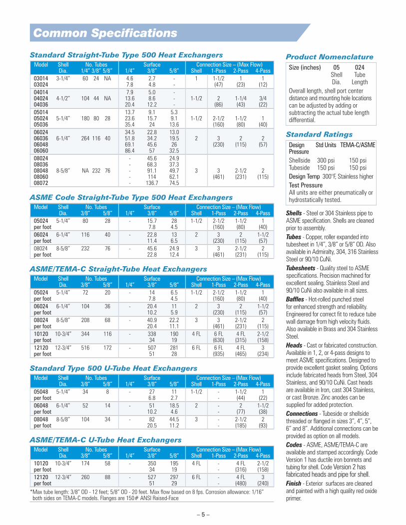
Standard Straight-Tube Type 500 Heat Exchangers Model Shell No. Tubes Surface Connection Size – (Max Flow) Dia. 1/4” 3/8” 5/8” 1/4” 3/8” 5/8” Shell 1-Pass 2-Pass 4-Pass 03014 3-1/4” 60 24 NA 4.6 2.7 - 1 1-1/2 1 1 03024 7.8 4.8 - (47) (23) (12)
04014 7.9 5.0 - 04024 4-1/2” 104 44 NA 13.6 8.6 - 1-1/2 2 1-1/4 3/4 04036 20.4 12.2 - (86) (43) (22)
05014 13.7 9.1 5.3 05024 5-1/4” 180 80 28 23.6 15.7 9.1 1-1/2 2-1/2 1-1/2 1 05036 35.4 24 13.6 (160) (80) (40)
06024 34.5 22.8 13.0 06036 6-1/4” 264 116 40 51.8 34.2 19.5 2 3 2 2 06048 69.1 45.6 26 (230) (115) (57) 06060 86.4 57 32.5
08024 - 45.6 24.9 08036 - 68.3 37.3 08048 8-5/8” NA 232 76 - 91.1 49.7 3 3 2-1/2 2 08060 - 114 62.1 (461) (231) (115) 08072 - 136.7 74.5
ASME Code Straight-Tube Type 500 Heat Exchangers Model Shell No. Tubes Surface Connection Size – (Max Flow) Dia. 3/8” 5/8” 1/4” 3/8” 5/8” Shell 1-Pass 2-Pass 4-Pass 05024 5-1/4” 80 28 - 15.7 28 1-1/2 2-1/2 1-1/2 1 per foot 7.8 4.5 (160) (80) (40)
06024 6-1/4” 116 40 - 22.8 13 2 3 2 1-1/2 per foot 11.4 6.5 (230) (115) (57)
08024 8-5/8” 232 76 - 45.6 24.9 3 3 2-1/2 2 per foot 22.8 12.4 (461) (231) (115)
ASME/TEMA-C Straight-Tube Heat Exchangers Model Shell No. Tubes Surface Connection Size – (Max Flow) Dia. 3/8” 5/8” 1/4” 3/8” 5/8” Shell 1-Pass 2-Pass 4-Pass 05024 5-1/4” 72 20 - 14 6.5 1-1/2 2-1/2 1-1/2 1 per foot 7.8 4.5 (160) (80) (40)
06024 6-1/4” 104 36 - 20.4 11 2 3 2 1-1/2 per foot 10.2 5.9 (230) (115) (57)
08024 8-5/8” 208 68 - 40.9 22.2 3 3 2-1/2 2 per foot 20.4 11.1 (461) (231) (115)
10120 10-3/4” 344 116 - 338 190 4 FL 6 FL 4 FL 2-1/2 per foot 34 19 (630) (315) (158)
12120 12-3/4” 516 172 - 507 281 6 FL 6 FL 4 FL 3 per foot 51 28 (935) (465) (234)
Standard Type 500 U-Tube Heat Exchangers Model Shell No. Tubes Surface Connection Size – (Max Flow) Dia. 3/8” 5/8” 1/4” 3/8” 5/8” Shell 1-Pass 2-Pass 4-Pass 05048 5-1/4” 34 8 - 27 11 1-1/2 - 1-1/2 1 per foot 6.8 2.7 - (44) (22)
06048 6-1/4” 52 14 - 51 18.5 2 - 2 1-1/2 per foot 10.2 4.6 - (77) (38)
08048 8-5/8” 104 34 - 82 44.5 3 - 2-1/2 2 per foot 20.5 11.2 - (185) (93)
ASME/TEMA-C U-Tube Heat Exchangers Model Shell No. Tubes Surface Connection Size – (Max Flow) Dia. 3/8” 5/8” 1/4” 3/8” 5/8” Shell 1-Pass 2-Pass 4-Pass 10120 10-3/4” 174 58 - 350 195 4 FL - 4 FL 2-1/2 per foot 34 19 - (316) (158)
12120 12-3/4” 260 88 - 527 297 6 FL - 4 FL 3 per foot 51 29 - (480) (240)
* Max tube length: 3/8” OD - 12 feet; 5/8” OD - 20 feet. Max fl ow based on 8 fps. Corrosion allowance: 1/16” both sides on TEMA-C models. Flanges are 150# ANSI Raised-Face
Product NomenclatureSize (inches) 05 024 Shell Tube Dia. Length
Overall length, shell port center distance and mounting hole locations can be adjusted by adding or subtracting the actual tube length differential.
Standard RatingsDesign Std Units TEMA-C/ASMEPressureShellside 300 psi 150 psiTubeside 150 psi 150 psi
Design Temp 300°F, Stainless higher
Test PressureAll units are either pneumatically or hydrostatically tested.
Shells - Steel or 304 Stainless pipe to ASME specifi cation. Shells are cleaned prior to assembly.
Tubes - Copper, roller expanded into tubesheet in 1/4”, 3/8” or 5/8” OD. Also available in Admiralty, 304, 316 Stainless Steel or 90/10 CuNi.
Tubesheets - Quality steel to ASME specifi cations. Precision machined for excellent sealing. Stainless Steel and 90/10 CuNi also available in all sizes.
Baffl es - Hot-rolled punched steel for enhanced strength and reliability. Engineered for correct fi t to reduce tube wall damage from high velocity fl uids. Also available in Brass and 304 Stainless Steel.
Heads - Cast or fabricated construction. Available in 1, 2, or 4-pass designs to meet ASME specifi cations. Designed to provide excellent gasket sealing. Options include fabricated heads from Steel, 304 Stainless, and 90/10 CuNi. Cast heads are available in Iron, cast 304 Stainless, or cast Bronze. Zinc anodes can be supplied for added protection.
Connections - Tubeside or shellside threaded or fl anged in sizes 3”, 4”, 5”, 6” and 8”. Additional connections can be provided as option on all models.
Codes - ASME, ASME/TEMA-C are available and stamped accordingly. Code Version 1 has ductile iron bonnets and tubing for shell. Code Version 2 has fabricated heads and pipe for shell.
Finish - Exterior surfaces are cleaned and painted with a high quality red oxide primer.

– 6 –
Straight-Tube Heat Exchangers
Commercial Standard – Common Dimensions Single-Pass Model A B C D E F G H J K-NPT L-NPT M N P R-NPT S-NPT T 03014 3-1/4 4-1/2 10 2-5/16 16-3/8 2-3/4 4-1/2 1-5/8 7/16 1/4 1 17-3/8 3-11/16 1/2 3/8 1-1/2 3/8 03024 20 26-3/8 27-3/8
04014 9 16-5/8 17-7/8 04024 4-1/4 6 19 3-1/8 29-5/8 3-1/2 4-1/4 1-3/4 7/16 1/4 1-1/2 27-7/8 4-7/16 5/8 3/8 2 - 04036 31 38-5/8 39-7/8
05014 9 17-1/8 19 05024 5-1/4 6-3/4 19 3-7/16 27-1/8 4 5-1/4 2 1/2x3/4 1/4 1-1/2 29 5 15/16 3/8 2-1/2 - 05036 31 39-1/8 41
06024 18-1/4 27-1/8 29-1/8 06036 6-1/4 7-3/4 30-1/4 4-1/16 39-1/8 4-1/2 6-1/4 2-1/2 1/2x3/4 3/8 2 41-1/8 5-7/16 1 1/2 3 - 06048 42-1/4 51-1/8 53-1/8 06060 54-1/4 63-1/8 65-1/8
08024 17 27-1/2 31-1/8 08036 29 39-1/2 43-1/8 08048 8-5/8 10-1/2 41 5-7/16 51-1/2 5-3/4 8-1/4 3-1/2 5/8x7/8 3/8 3 55-1/8 7-1/16 1-13/16 1/2 3 - 08060 53 63-1/2 67-1/8 08072 65 75-1/2 79-1/8
5”, 6” & 8” ASME Code – Common Dimensions Single-Pass Model A B C D E F G H J K-NPT L-NPT M N P R-NPT S-NPT T 05048 5-1/4 6-3/4 42 3-7/8 51-5/8 4 5-1/4 2 1/2x3/4 1/4 1-1/2 53-1/2 5-3/4 15/16 3/8 2-1/2 - 06048 6-1/4 7-3/4 41-1/2 4-7/16 51-3/4 4-1/2 6-1/4 2-1/2 1/2x3/4 3/8 2 53-3/4 6-1/8 1 1/2 3 - 08048 8-5/8 10-1/2 40 5-7/8 52-3/8 5-3/4 8-1/4 3-1/2 5/8x7/8 3/8 3 56 8 1-13/16 1/2 3 -
10” & 12” ASME/TEMA-C – Common Dimensions Single-Pass Model A B C D E F G H J K-NPT L-NPT M N P R-NPT S-NPT T 10120 10-3/4 145-3/8 109-1/2 11-1/8 11-1/8 6-13/16 10 13-3/4 96 2-1/4 12-1/2 4 1-3/8 7 4FL 6FL -
12120 12-3/4 145-3/4 107-1/2 12-7/16 12-7/16 6-15/16 11 15-3/4 94 2-1/4 14-1/2 5 1-3/8 8-1/4 6FL 6FL -
All models are available in other lengths. Apply the appropriate dimension changes to all length measurements along the centerline. Maximum tube length for 3/8” tubing is 12 feet. Maximum tube length for 5/8” tubing is 20 feet. FL indicates ANSI 150 lb. RF fl ange. Code design models are equipped with bottom drain only on the shell side. Bonnet vents may not be tapped unless required or if equipped with zinc anodes.
SINGLE-PASS STANDARD and CODE TWO-PASS STAN
SINGLE-PASS ASME/TEMA-C TWO-PASS A
– 7 –
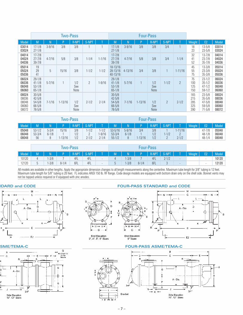
Two-Pass Four-Pass Model M N P R-NPT S-NPT T M N P R-NPT S-NPT T Weight E2 Model 03014 17-1/8 3-9/16 3/8 3/8 1 1 17-1/8 3-9/16 3/8 3/8 3/4 1 18 13-5/8 03014 03024 27-1/8 27-1/8 23 23-5/8 03024 04014 17-7/8 17-7/8 32 13-7/8 04014 04024 27-7/8 4-7/16 5/8 3/8 1-1/4 1-1/16 27-7/8 4-7/16 5/8 3/8 3/4 1-1/4 41 23-7/8 04024 04036 39-7/8 39-7/8 52 35-7/8 04036 05014 19 18-13/16 45 13-3/8 05014 05024 29 5 15/16 3/8 1-1/2 1-1/2 28-13/16 4-13/16 3/4 3/8 1 1-11/16 55 23-3/8 05024 05036 41 40-13/16 75 35-3/8 05036 06024 29-1/8 29-1/8 75 23-1/2 06024 06036 41-1/8 5-7/16 1 1/2 2 1-9/16 41-1/8 5-7/16 1 1/2 1-1/2 2 100 35-1/2 06036 06048 53-1/8 See 53-1/8 See 125 47-1/2 06048 06060 65-1/8 Note 65-1/8 Note 150 59-1/2 06060 08024 30-5/8 30-5/8 165 23-5/8 08024 08036 42-5/8 42-5/8 215 35-5/8 08036 08048 54-5/8 7-1/16 1-13/16 1/2 2-1/2 2-1/4 54-5/8 7-1/16 1-13/16 1/2 2 2-1/2 285 47-5/8 08048 08060 66-5/8 See 66-5/8 See 325 59-5/8 08060 08072 78-5/8 Note 78-5/8 Note 390 71-5/8 08072
Two-Pass Four-Pass Model M N P R-NPT S-NPT T M N P R-NPT S-NPT T Weight E2 Model 05048 53-1/2 5-3/4 15/16 3/8 1-1/2 1-1/2 53-5/16 5-9/16 3/4 3/8 1 1-11/16 47-7/8 05048 06048 53-3/4 6-1/8 1 1/2 2 1-9/16 53-3/4 6-1/8 1 1/2 1-1/2 2 48-1/8 06048 08048 56 8 1-13/16 1/2 2-1/2 2-1/4 55-1/2 8 1-13/16 1/2 2 2-1/2 48-1/4 08048
Two-Pass Four-Pass Model M N P R-NPT S-NPT T M N P R-NPT S-NPT T Weight E2 Model 10120 4 1-3/8 7 4FL 4FL - 4 1-3/8 7 4FL 2-1/2 - - 10120 12120 5 1-3/8 8-1/4 6FL 4FL - 5 1-3/8 8-1/4 6FL 3 - - 12120
All models are available in other lengths. Apply the appropriate dimension changes to all length measurements along the centerline. Maximum tube length for 3/8” tubing is 12 feet. Maximum tube length for 5/8” tubing is 20 feet. FL indicates ANSI 150 lb. RF fl ange. Code design models are equipped with bottom drain only on the shell side. Bonnet vents may not be tapped unless required or if equipped with zinc anodes.
NDARD and CODE FOUR-PASS STANDARD and CODE
ASME/TEMA-C FOUR-PASS ASME/TEMA-C

– 8 –
U-Tube Heat Exchangers
Commercial Standard U-Tube – Common Dimensions
Model A B C D E F G H J K-NPT L-NPT 05048 5-1/4 6-3/4 48-1/2 3-7/16 57-5/16 4 4-1/2 2 1/2x3/4 1/4 1-1/2
06048 6-1/4 7-3/4 49 4-1/16 58-3/8 4-1/2 6-1/4 2-1/2 1/2x3/4 3/8 2
08048 8-5/8 10-1/2 50-1/2 5-7/16 61-13/16 5-3/4 8-1/4 3-1/2 5/8x7/8 3/8 3
5”, 6” & 8” ASME Code Models
Model A B C D E F G H J K-NPT L-NPT 05048 5-1/4 6-3/4 48-1/2 3-7/8 57-5/16 4 5-1/4 2 1/2x3/4 1/4 1-1/2
06048 6-1/4 7-3/4 49 4-7/16 58-3/8 4-1/2 6-1/4 2-1/2 1/2x3/4 3/8 2
08048 8-5/8 10-1/2 50-1/2 5-7/8 61-13/16 5-3/4 8-1/4 3-1/2 5/8x7/8 3/8 3-
10” & 12” ASME/TEMA-C Models
Model A B C D E F G H J K L 10120 10-3/4 148-3/4 121 8-15/16 12 6-13/16 10 13-3/4 105 2-1/4 12-1/2
12120 12-3/4 153-1/2 122-1/2 10-9/16 13-1/2 6-15/16 11 15-3/4 109 2-1/4 14-1/2
All models are available in other lengths. Apply the appropriate dimension changes to all length measurements along the centerline. Maximum tube length for 3/8” tubing is 12 feet. Maximum tube length for 5/8” tubing is 20 feet. FL indicates ANSI 150 lb. RF fl ange.
TWO-PASS U-TUBE MODELS
TWO-PASS U-TUBE ASME/TEMA-C
– 9 –
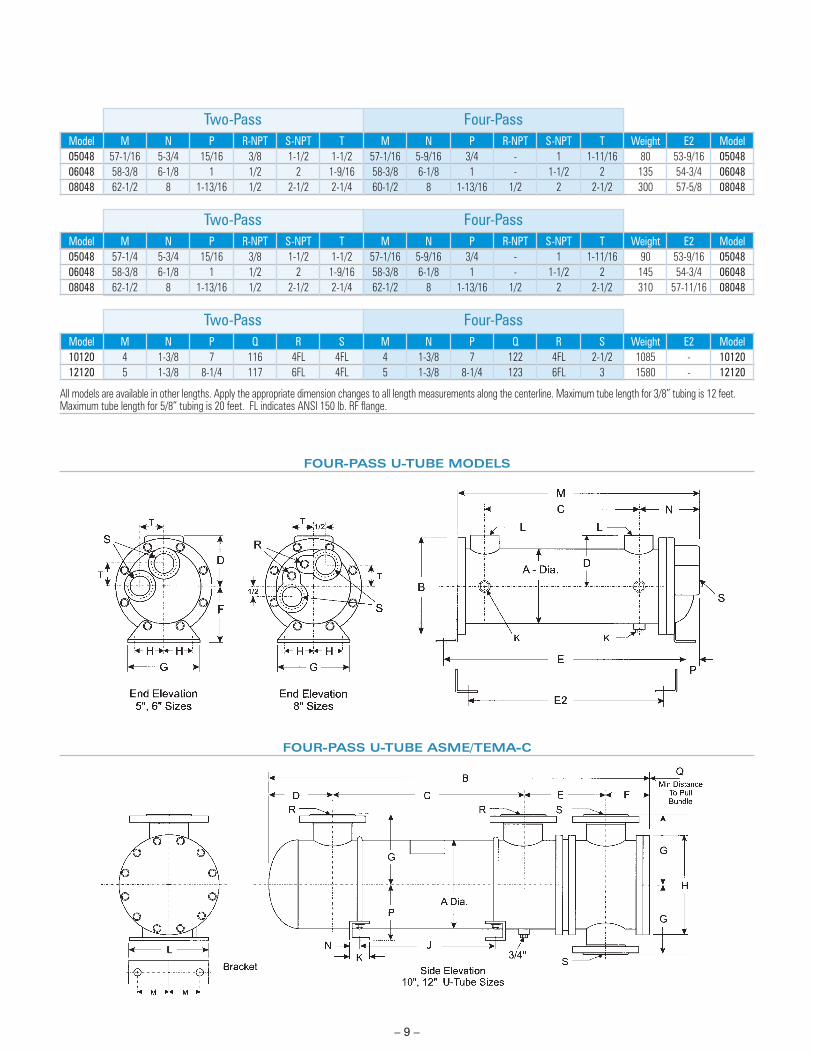
FOUR-PASS U-TUBE MODELS
FOUR-PASS U-TUBE ASME/TEMA-C
Two-Pass Four-Pass Model M N P R-NPT S-NPT T M N P R-NPT S-NPT T Weight E2 Model 05048 57-1/16 5-3/4 15/16 3/8 1-1/2 1-1/2 57-1/16 5-9/16 3/4 - 1 1-11/16 80 53-9/16 05048 06048 58-3/8 6-1/8 1 1/2 2 1-9/16 58-3/8 6-1/8 1 - 1-1/2 2 135 54-3/4 06048 08048 62-1/2 8 1-13/16 1/2 2-1/2 2-1/4 60-1/2 8 1-13/16 1/2 2 2-1/2 300 57-5/8 08048
Two-Pass Four-Pass Model M N P R-NPT S-NPT T M N P R-NPT S-NPT T Weight E2 Model 05048 57-1/4 5-3/4 15/16 3/8 1-1/2 1-1/2 57-1/16 5-9/16 3/4 - 1 1-11/16 90 53-9/16 05048 06048 58-3/8 6-1/8 1 1/2 2 1-9/16 58-3/8 6-1/8 1 - 1-1/2 2 145 54-3/4 06048 08048 62-1/2 8 1-13/16 1/2 2-1/2 2-1/4 62-1/2 8 1-13/16 1/2 2 2-1/2 310 57-11/16 08048
Two-Pass Four-Pass Model M N P Q R S M N P Q R S Weight E2 Model 10120 4 1-3/8 7 116 4FL 4FL 4 1-3/8 7 122 4FL 2-1/2 1085 - 10120 12120 5 1-3/8 8-1/4 117 6FL 4FL 5 1-3/8 8-1/4 123 6FL 3 1580 - 12120
All models are available in other lengths. Apply the appropriate dimension changes to all length measurements along the centerline. Maximum tube length for 3/8” tubing is 12 feet. Maximum tube length for 5/8” tubing is 20 feet. FL indicates ANSI 150 lb. RF fl ange.
– 10 –
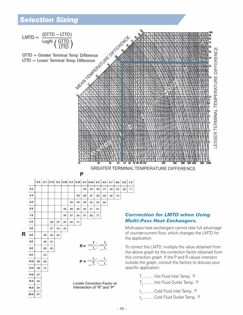
Selection Sizing
Corrrection for LMTD when Using Multi-Pass Heat Exchangers.Multi-pass heat exchangers cannot take full advantage of counter-current fl ow, which changes the LMTD for the application.
To correct the LMTD, multiply the value obtained from the above graph by the correction factor obtained from this correction graph. If the P and R values intersect outside the graph, consult the factory to discuss your specifi c application.
T1 ......... Hot Fluid Inlet Temp, °F T2 ......... Hot Fluid Outlet Temp, °F
t1 .......... Cold Fluid Inlet Temp, °F t2 .......... Cold Fluid Outlet Temp, °F

– 11 –
Sample Calculation To Select the Right Type 500 Heat Exchanger.Conditions
Process Fluid .......... 20 GPM of SAE 10 Oil to be cooled from 140° to 120°F.
Cooling Medium .... Water at 85°F. Assume a 10° maximum temperature rise.
Cooler Design......... 4-Pass design is selected to conserve water and energy usage.
Thermal Duty Determination
Q = ΔT • Thermal Duty Value (Chart) • GPM (or air SCFM)Q = (140-120) • 204 • 20Q = 81,600 Btuh (Btu’s per hour)
Determine Cooling Water Flow Required
Q = Δt(allowable temp rise) • Flow Constant • GPM
Q ΔT • Flow Constant
= GPM = 81,000 10 • 500 = 16.3 GPM
Determine Exchanger Surface Required
QArea = U • Log Mean Temp DifferenceQ = 81,600 Btuh
“U-Value” is obtained from the chart. For light oil the range is from 70-100. Assuming the oil to be typical machine lubricant with moderate fouling characteristics we will use 80 as a conservative U-Value.
Calculate LMTD from graph on facing page
140° — 120° (Oil ΔT) -95° — -85° (Water ΔT) 45° — 35°
Thus.. greater temperature difference = 45° lesser temperature difference = 35°
Reading from the graph, LMTD = 40°F
Area = Q
= 81,600 Btuh
U • LMTD 80 • 40 = 25.5 sq. ft.
Select a Type 500 Heat Exchanger
Refer to the Common Specifi cation chart on page fi ve. Notice that Model 05036 has 24 square feet of surface and is too small for the application.
Model 06036 has 116 tubes and contains 34 sq. ft. of tube surface. Now assure the max fl ow rate is not exceeded. The previous calculated fl ow rate is 16.3 GPM. The 06036 has a maximum fl ow rate of 57 GPM. This is acceptable.
In the event that the required fl ow rate exceeds the maximum fl ow rate for the heat exchanger, a larger model is required.
Calculating Actual Heat Exchanger Length
You can calculate the actual length of the heat exchanger required to satisfy a given set of conditions. The typical tube surface contained per linear foot of tubing is:
1/4” Tubing ….. 0.0655 sq. ft per ft. of tubing3/8” Tubing ….. 0.0982 sq. ft per ft. of tubing5/8” Tubing ….. 0.1636 sq. ft per ft. of tubing
Linear feet of tubing required = Area Required
No. of • Area Per Tubes Foot
Using the previous example…
Linear Feet = 26 sq. ft. = 2.28 feet 116 tubes • 0.0982
Calculating Tube Side Velocity
You can calculate the velocity of the fl uid fl owing through the tubes. Velocity should fall between 2 and 6 feet per second and not exceed 8 feet per second. Velocity factors for standard tubing are:
1/4” Tubing ….. 9.66 velocity factor, (Vf)3/8” Tubing ….. 4.02 velocity factor, (Vf)5/8” Tubing ….. 1.47 velocity factor, (Vf)
Using the previous example…
Velocity (ft./sec.) = 16.3 (GPM) • 4.02 (Vf)• 4 (Passes)
116 (No. of Tubes) = 2.26 feet per second in the tubes
Common Heat Transfer Formulas
Btuh = Btu/min. • 60 Btuh = Horsepower • 2,545 Btuh = Kw • 3,413 Btuh Oil = GPM (Oil) • 204 • ΔT Btuh Water = GPM (Water) • 500 • ΔT LMTD °F = LMTD °C • 1.8
TYPICAL THERMAL DUTY VALUES
Liquid Constant Spec. Spec. °C °FType Value Gravity Heat Liters/min Gallons/minWater 500 x 1.0 x 1.0 = 238 or 50050% Ethlene Glycol 500 x 1.04 x .83 = 203 or 428Oil (150 SSU) 500 x .85 x .48 = 97 or 204Air 4.58 x - x .241 = 110 SCFM
TYPICAL OVERALL U-VALUES
Hot Fluid Cooling Fluid U-Value (typical)Steam Water 300-500Steam Light Oil (SAE 10) 70-100Steam Heavy Oil 40-50Steam Air 30-40Water Water (85°F) 275-325Oil (SAE 10) Water (85°F) 70-100Oil (SAE 30) Water (85°F) 60-8050% Glycol Water 150-180
Note: Higher U-Values apply to clean, low viscosity fl ows. Use lower U-Values for higher pressure,
dirty or viscous fl uids as they tend to foul a heat exchanger.

Divisions:
API Airtech ISO-9001 Certifi ed
Air Cooled Aluminum Heat Exchangers91 North Street • P.O. Box 68
Arcade, New York 14009-0068
(585) 496-5755 • Fax: (585) 496-5776
API Basco ISO-9001 Certifi ed
Basco®/Whitlock® Shell & Tube Heat Exchangers2777 Walden Avenue
Buffalo, New York 14225
(716) 684-6700 • Fax: (716) 684-2129
API Schmidt-Bretten AmericasPlate Heat Exchangers and Thermal Systems2777 Walden Avenue
Buffalo, New York 14225
(716) 684-6700 • Fax: (716) 684-2129
API Schmidt-Bretten GmbH & Co. KG ISO-9001 Certifi ed
Plate Heat Exchangers and Thermal SystemsLangenmorgen 4
D-75015 Bretten, Germany
(49)725253-0 • Fax: (49)725253-200
API Heat Transfer (Suzhou) Co., Ltd.Air Cooled Aluminum Heat ExchangersShell & Tube Heat ExchangersPlate Heat Exchangers156 Qingqiu Street, 3rd District
Suzhou Industrial Park
Suzhou, Jiangsu 215126 China
(86)512-88168000 • Fax: (86)512-88168003
API Heat Transfer Inc.2777 Walden AvenueBuffalo, New York 14225(716) 684-6700www.apiheattransfer.com
Contact your local API Sales Representative or API Heat Transfer directlytoll-free: 1-877-API-HEATe-mail: [email protected]
Other Products Available from API Heat TransferOptiDesign®
Straight-tube, removable bundle exchangers made from standard components. Floating tubesheet for seal leak detection and easy maintenance. Diameters from 3” (7.62 cm) to 42” (106.68 cm). ASME, API, TEMA, ABS and other codes available.
Hubbed Shell and Tube Heat Exchangers
Straight or U-tube, fi xed or removable tubesheet general purpose exchangers designed to cool oil, water, compressed air and other industrial fl uids. A variety of port confi gurations and materials are available. Diameters from 2” (5.08 cm) to 8” (20.32 cm).
A wide variety of TEMA types are available using pre-engineered or custom designs in vari-ous sizes and materials. Shell diameters from 6” (15.24 cm) to 144” (365.76 cm), ASME, TEMA, API, ABS, TUV, PED and other code constructions available.
Brazed Plate Heat Exchangers
Off-the-shelf, standard units refl ect the latest in plate heat exchanger technology for maximum performance and low cost. Ideal for OEM or aftermarket applications. Many models stocked and ready to ship. Models for process or refrigeration applications.
Extended Surface “ES” Exchangers Air-Cooled Heat Exchangers
High effi ciency, brazed aluminum coolers for cooling a wide variety of liquids and gases with ambient air. Lightweight, yet rugged. Capable of cooling multiple fl uids in single unit. Models can be supplied with cooling fan and a variety of drives.
Gasketed Plate Heat Exchangers
The Schmidt line of gasketed plate & frame heat exchangers provide excellent heat transfer in a compact space. Plates are pressed from stainless steel, titanium and other alloys. Gaskets of nitrile, EPDM, Viton®, compressed fi ber and Tefl on® are used. Capacities range from 0.5 to 10,000 GPM.
Pipeline Aftercoolers
Straight-tube, counterfl ow aftercoolers designed to yield cool, dry compressed air. Available with or without accompanying moisture separators and constructed to a wide variety of design codes. Diameters from 3” (7.62 cm) to 42” (106.68 cm).
TEMA Shell and Tube
Form 500-322 11/10 © 2000 API Heat Transfer Printed in USA
Unique, patented plate-fi n design for centrifugal or axial compressor intercooler and aftercooler applications and minimal pressure loss. Design eliminates separators. ASME code design is standard. Diameters from 20” (50.8 cm) to 168” (426.72 cm).


![The Legislative Building [ BASCO ]](https://static.fdocuments.in/doc/165x107/55cf92b7550346f57b990087/the-legislative-building-basco-.jpg)
