Bas-relief Modeling from RGB Monocular Images with ...
12
Bas-relief Modeling from RGB Monocular Images with Regional Division Characteristics Xinli Wu ( [email protected] ) Zhejiang Sci-Tech University Jiali Luo Zhejiang Sci-Tech University Minxiong Zhang Zhejiang Sci-Tech University Wenzhen Yang Zhejiang Sci-Tech University Research Article Keywords: Monocular image, bas-relief modeling, region division, shading recovery shape, 3D reconstruction Posted Date: November 17th, 2021 DOI: https://doi.org/10.21203/rs.3.rs-1063376/v1 License: This work is licensed under a Creative Commons Attribution 4.0 International License. Read Full License
Transcript of Bas-relief Modeling from RGB Monocular Images with ...

Bas-relief Modeling from RGB Monocular Imageswith Regional Division CharacteristicsXinli Wu ( [email protected] )
Zhejiang Sci-Tech UniversityJiali Luo
Zhejiang Sci-Tech UniversityMinxiong Zhang
Zhejiang Sci-Tech UniversityWenzhen Yang
Zhejiang Sci-Tech University
Research Article
Keywords: Monocular image, bas-relief modeling, region division, shading recovery shape, 3Dreconstruction
Posted Date: November 17th, 2021
DOI: https://doi.org/10.21203/rs.3.rs-1063376/v1
License: This work is licensed under a Creative Commons Attribution 4.0 International License. Read Full License
Bas-relief Modeling from RGB Monocular Images with Regional Division
Characteristics
Xinli Wu1, Jiali Luo , Minxiong Zhang , Wenzhen Yang,
Virtual Reality Laboratory of Zhejiang Sci-Tech University, Hangzhou 310018
Abstract: Bas-relief, a form of sculpture art representation, has the general characteristics of sculpture art and satisfies people’s visual
and tactile feelings by fully leveraging the advantages of painting art in composition, subject matter, and spatial processing. Bas-relief
modeling using images is generally classified into the method based on the three-dimensional (3D) model, that based on the image
depth restoration, and that based on multi-images. The 3D model method requires the 3D model of the object in advance. Bas-relief
modeling based on the image depth restoration method usually either uses a depth camera to obtain object depth information or
restores the depth information of pixels through the image. Bas-relief modeling based on the multi-image requires a short running time
and has high efficiency in processing high resolution level images. Our method can automatically obtain the pixel height of each area
in the image and can adjust the concave–convex relationship of each image area to obtain a bas-relief model based on the RGB
monocular image. First, the edge contour of an RGB monocular image is extracted and refined by the Gauss difference algorithm
based on tangential flow. Subsequently, the complete image contour information is extracted and the region-based image segmentation
is used to calibrate the region. This method has improved running speed and stability compared with the traditional algorithm. Second,
the regions of the RGB monocular image are divided by the improved connected-component labeling algorithm. In the traditional
region calibration algorithm, the contour search strategy and the inner and outer contour definition rules of the image considered result
in a low region division efficiency. This study uses an improved contour-based calibration algorithm. Then, the 3D pixel point cloud of
each region is calculated by the shape-from-shading algorithm. The concave–convex relationships among these regions can be
adjusted by human–computer interaction to form a reasonable bas-relief model. Lastly, the bas-relief model is obtained through
triangular reconstruction using the Delaunay triangulation algorithm. The final bas-relief modeling effect is displayed by OpenGL. In
this study, six groups of images are selected for conducting regional division tests, and the results obtained by the proposed method
and other existing methods are compared. The proposed algorithm shows improved image processing running time for different
complexity levels compared with the traditional two-pass scanning method and seed filling method (by approximately 2 s) and with
the contour tracking method (by approximately 4 s). Next, image depth recovery experiments are conducted on four sets of images,
namely the “ treasure seal,” “Wen Emperor seal,” “lily pattern,” and “peacock pattern,” and the results are compared. The depth of the
image obtained by the traditional algorithm is generally lower than the actual plane, and the relative height of each region is not
consistent with the actual situation. The proposed algorithm provides height values consistent with the height value information judged
in the original image and adjusts the accurate concave–convex relationships. Moreover, the noise in the image is reduced and relatively
smooth surfaces are obtained, with accurate concave–convex relationships. The proposed bas-relief model based on RGB monocular
images can automatically determine the pixel height of each image area in the image and adjust the concave–convex relationship of
each image area. In addition, it can recover the 3D model of the object from the image, enrich the object of bas-relief modeling, and
expand the creation space of bas-relief, thereby improving the production efficiency of the bas-relief model based on RGB monocular
images. The method has certain shortcomings, which require further exploration. For example, during the process of image contour
extraction for region division, small differences exist between the obtained result and the actual situation, which can in turn affect the
image depth recovery in the later stage. In addition, partial distortion may occur in the process of 3D reconstruction, which requires
further research on point cloud data processing to reconstruct a high-quality three-dimensional surface.
Key words: Monocular image; bas-relief modeling; region division; shading recovery shape; 3D reconstruction
1 Xinli Wu

0 Introduction
Sculpture is a ubiquitous art form in human life. A sculptor gradually transforms a two-dimensional planar
drawing to a three-dimensional (3D) representation by applying the shadow expression method. By using various
materials to realize the 3D representation of different images, the history of relief sculpture has been promoted.
Bas-relief, which is a form of sculpture art, not only has the general characteristics of sculpture art but also satisfies
people’s visual and tactile feelings. It can fully leverage the advantages of painting art in composition, subject, matter, and space processing.
In recent years, scholars around the world have
conducted in-depth research on bas-relief modeling. The use of images for bas-relief modeling is usually divided
into three categories: bas-relief modeling based on 3D models through mapping, bas-relief modeling based on
image depth recovery, and bas-relief modeling based on multiple images. The 3D model method requires the 3D
model of the object in advance. Bas-relief modeling based on the image depth restoration method usually either
uses a depth camera to obtain object depth information or restores the depth information of pixels through the
image. The complexity of the scene often results in a low grid drawing efficiency after the point cloud is merged.
Therefore, the merged network model needs to be simplified. Moreover, this method uses an external device, which
requires a high position for shooting. Bas-relief modeling based on the multi-image requires a short running time
and has high efficiency in processing high resolution level images. This method requires compact external devices
for acquiring the depth information and a low shooting position; however, it uses a relative more complex
algorithm. Therefore, this study proposes a bas-relief modeling method based on region division. Monocular
images are taken as the research object to explore the key techniques of region division, depth restoration, and
surface 3D reconstruction. This method can automatically obtain the pixel height of each area in the image and can
adjust the concave–convex relationship of each image area to obtain a bas-relief model based on the RGB
monocular image.
The bas-relief modeling method based on the 3D model compression method mainly involves scanning of the
target object from multiple angles using a scanning device to obtain a 3D model of the object in the real world and
finally reconstructing a complete 3D shape. Cignoni [1], who is the pioneer in the research on bas-relief production
through 3D model mapping, applied perspective projection and depth compression to generate relief models. This
laid the foundation for subsequent research on 3D model mapping. Later, Weyrich et al. [2] used a nonlinear
compression function to compress the gradient domain. This method preserves the details of the image well and
provides gentler contours. Zhang et al. [3] directly compressed the input 3D model to obtain a suitable depth of the
dynamic range. However, the high dynamic range (HDR)-based method can omit some details in the model,
resulting in the bas-relief model missing the details in a small area. Zhang Y.W. et al. [4] proposed a relief that
adaptively generates lighting conditions for the lighting effect on the appearance of bas-relief. Wei et al. [5] used a
two-step mesh smoothing mechanism as a bridge to perform appropriate operations on the smooth base layer and
the detail layer, which can retain more details during compression. In the bas-relief production process of 3D model
mapping, the reverse operation from the gradient domain to the spatial domain is relatively time consuming. Kerber
et al. [6] used programmable hardware to realize the real-time generation of relief models. Zhang et al. [7] proposed
a real-time interactive relief texture model construction method through gradient domain compression and texture
mapping.
The key to the bas-relief modeling method based on the RGB-D monocular image depth estimation method is
to obtain the depth information of the image. Currently, image depth information can be obtained through two main
methods. One is to use a depth camera to obtain object depth information. A depth image contains pixels, each of
which stores the depth value of a specific point of the target object. In the case that the internal and external
parameters of the camera are known, the complete depth information of the object to be obtained is acquired from
the photographs taken from multiple angles. Finally, the complete depth information of the target object is obtained
through stitching. The other method is to recover the depth information of the pixels through the image, namely
using multi-angle depth image stitching. Commonly, either the relative relationship between pixels is used to merge
depth images or the scattered spatial points that have no connection relationship are directly merging. The
complexity of the scene leads to a low grid drawing efficiency after the point cloud is merged. Hence, the merged
grid model needs to be simplified. Moreover, the external equipment used in this method is complicated and
requires a high position for shooting.
In the bas-relief modeling method based on multi-images, the 3D model of the real object is recovered through
images from different angles in the same scene. In small scenes, feature points are usually tracked by
Kanade–Lucas–Tomasi (KLT) trackers or some other tracking methods [8][9]. In large scenes, motion-based
structure recovery [10] can process high-level images by adopting the main principle of processing images into
blocks and layers. This method has a short running time and high efficiency when processing high- resolutionlevel
images. The method of obtaining depth images through multi-images requires more concise external equipment for
acquiring depth information and lower shooting positions. However, it requires a more complex algorithm.
In summary, the current prerequisite for bas-relief modeling based on the 3D model through mapping is that
the 3D model of the object already exists. However, most objects that are targeted for bas-relief representation do
not have the original 3D models. Moreover, the complexity of the scene causes a low grid drawing efficiency after
the point cloud is merged in the bas-relief modeling methods based on the image for depth recovery and those
based on multi-images. Therefore, the merged network model needs to be simplified. Furthermore, the external
equipment used by this method requires a high shooting location. Hence, this paper proposes a bas-relief modeling
method for RGB monocular images based on regional division. Taking monocular images as the research object,
this paper focuses on exploring the key technologies of image regional division, depth recovery, and surface 3D
reconstruction. The proposed method can automatically obtain the pixel height value of each image area in the
image and adjust the concave–convex relationship of each image area to obtain a bas-relief model based on RGB
monocular images.
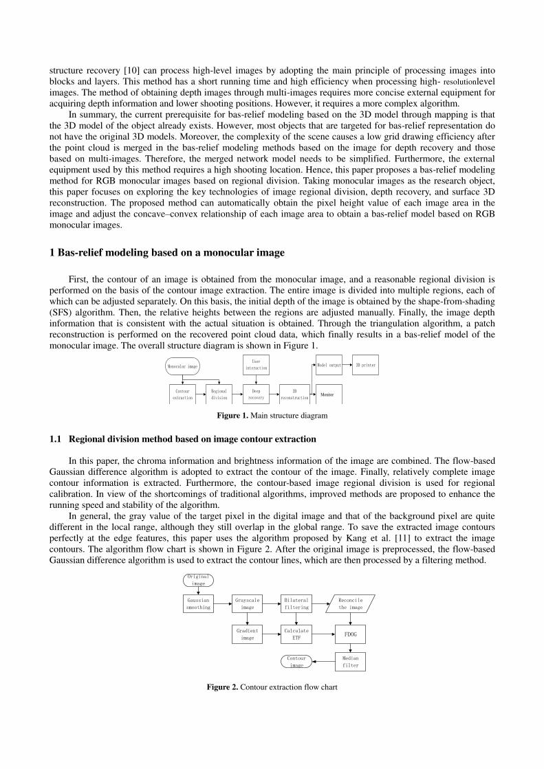
1 Bas-relief modeling based on a monocular image
First, the contour of an image is obtained from the monocular image, and a reasonable regional division is
performed on the basis of the contour image extraction. The entire image is divided into multiple regions, each of
which can be adjusted separately. On this basis, the initial depth of the image is obtained by the shape-from-shading
(SFS) algorithm. Then, the relative heights between the regions are adjusted manually. Finally, the image depth
information that is consistent with the actual situation is obtained. Through the triangulation algorithm, a patch
reconstruction is performed on the recovered point cloud data, which finally results in a bas-relief model of the
monocular image. The overall structure diagram is shown in Figure 1.
Contour
extraction
Regional
division
Deep
recovery
Monocular imageUser
interaction
3D
reconstruction Monitor
Model output 3D printer
Figure 1. Main structure diagram
1.1 Regional division method based on image contour extraction
In this paper, the chroma information and brightness information of the image are combined. The flow-based
Gaussian difference algorithm is adopted to extract the contour of the image. Finally, relatively complete image
contour information is extracted. Furthermore, the contour-based image regional division is used for regional
calibration. In view of the shortcomings of traditional algorithms, improved methods are proposed to enhance the
running speed and stability of the algorithm.
In general, the gray value of the target pixel in the digital image and that of the background pixel are quite
different in the local range, although they still overlap in the global range. To save the extracted image contours
perfectly at the edge features, this paper uses the algorithm proposed by Kang et al. [11] to extract the image
contours. The algorithm flow chart is shown in Figure 2. After the original image is preprocessed, the flow-based
Gaussian difference algorithm is used to extract the contour lines, which are then processed by a filtering method.
Original
image
Gaussian
smoothing
Grayscale
image
Bilateral
filtering
Reconcile
the image
Gradient
image
Calculate
ETFFDOG
Contour
image
Median
filter
Figure 2. Contour extraction flow chart

In this paper, the region is divided on the basis of the contour image. In the traditional contour region
calibration algorithm, the regional division efficiency is low because of the use of the contour search strategy and
the internal and external contour definition rules of the image, and it is time consuming. Therefore, this paper
improves the contour-based calibration algorithm. For this purpose, first, the extracted contour is refined, and the
contour lines are refined into single pixels. Then, the improved regional calibration method is used to divide the
image region. Figure 3 shows the improved algorithm flow chart.
Contour image
Connected domain
calibration
Original image
Regional
division result
image
Regional image
Separate extraction of
each region
Contour refinement
Figure 3. Contour-based regional division of an image
Contour image refinement aims to remove unnecessary contour points and only retain the skeleton points of
the contour. The specific process of contour image refinement is shown in Figure 4.
Original image
Whether it is a non-
skeleton point
Terminate
Delete non-skeleton
points
Distinguish between
contour edge points and
midpoints
YES
NO
Figure 4. Contour image refinement flow chart
In this paper, the contour marking algorithm is used to divide the region. Assume a binary image whose
background is white and contour to be refined is black, the value of white pixels is 0, and that of black pixels is 1.
The specific process is as follows.
1) From left to right, the image pixels are traversed from top to bottom. When the foreground pixel point P is
scanned (the first foreground pixel point to be traversed), the pixel point is not marked. At this time, this
foreground pixel point is assigned with a new label number. Moreover, the contour of the pixel is traversed
according to the connection rule, and it is assigned the same label number. Finally, the process returns to the
original foreground pixel.
2) During the traversal process, if the traversed foreground pixel 'P is encountered, traversal is continued to the
right and the pixel is labeled with a value consistent with the label number of 'P .
3) In the traversal process, the contour is traversed when unlabeled foreground pixel Q
is encountered. All

foreground pixels on the path are assigned new label numbers label+.
4) When the second labeled contour is encountered for the first time in the traversal process, the background
pixel on the right is marked as the label number of the second contour. When the second labeled contour is
encountered for the second time, the label number on the right is the same as the label number of the first
contour.
5) The process terminates.
1.2 Deep recovery
The original point cloud data of the image pixels is obtained by using the SFS algorithm [12]. However, the
difficulty of the SFS algorithm for image 3D surface reconstruction is that the relative concave–convex relationship
between objects is blurred, owing to which the relative concave–convex relationship between image regions cannot
be accurately judged [13]. Therefore, although this method can obtain satisfactory partial reconstruction effects,
due its shortcomings, the overall structure of an image cannot be accurately achieved [14]. This paper proposes an
interactive SFS algorithm to improve the 3D surface reconstruction effect of the traditional SFS algorithm. The
specific process of the interactive algorithm is shown in Figure 5.
Original image
Regional division
Extract the image
separately for
each region
Point cloud data
SFS algorithm
Contour
extraction
Whether the concave-convex
relationship between regions is
correct
Whether the internal concave-
convex relationship of each region
is correct
Interactively
adjust the
hierarchical
concave-convex
relationship by
users
Interactively
adjust the
concave-convex
relationship
within the region
Figure 5. Flow chart of region-based image depth recovery
The algorithm has low complexity and high running speed in the process of obtaining the solution. The
specific solution process is as follows.
0
11
1),(
)),(),,((),()],([
2222
ss
ss
qpqp
qqppyxE
yxqyxpRyxEyxzf
where ( , )E x y is the image brightness; ( , )R x y is the image brightness reconstructed from the reflection
model; , ,1 Tp q ( ) is the normal vector of surface region; and ( , ,1)T
s sp q is the incident direction.
First, the reflection function ),( qpR
is discretized as follows.
)1,(),(
),1(),(
yxzyxzy
zq
yxzyxzx
zp
The brightness equation is

0
)]1,(),(),,1(),([),(
)),(),,((),()],([
yxzyxzyxzyxzRyxE
yxqyxpRyxEyxzf
Then, the Taylor formula is applied for expansion, taking low-order functions as the main processing object:
0),(
]),([)],(),([)],([)],([
111
yxdz
yxzdfyxzyxzyxzfyxzf
nnn
After iterative calculation, the depth ( , )n
z x y is obtained. On this basis, the relative concave–convex
relationship in the image and the concave–convex relationship within each region are obtained through human
interaction. Finally, the image depth information that meets the actual situation is obtained.
1.3 Surface reconstruction
The point cloud data are optimized by the triangulation algorithm with the goal to obtain a symmetrical and
efficient final surface. To achieve symmetry, researchers have combined the properties of triangulation and the
optimal shape criterion, most of them using the Delaunay criterion [15][16][17]. These algorithms improve the
calculation speed as much as possible while ensuring the uniform shape. In this paper, the Delaunay triangulation
algorithm is used to triangulate the point cloud. The final bas-relief modeling effect is displayed by OpenGL. The
basic steps are shown in Figure 6.
(1) A big triangle that can contain all points is constructed, and it is put in the triangle linked list.
(2) The points for construction are inserted in turn. The circumcircle of the extended edge containing the
insertion point is obtained while facing the insertion point; the common edge is deleted, and finally, the insertion
point is connected with the vertices of the triangle in turn to complete the operation of an insertion point.
(3) The optimization criteria are used to optimize the new triangle, which is then put into the triangle linked
list.
(4) Steps (2) and (3) are repeated to obtain the complete triangulation data.
D
A
B
C
P
D
A
B
C
P
(a) Insert a new node (b) Determine the triangle
D
A
B
C
P
D
A
B
C
P
(c) Delete common edge (d) Complete the new triangle
Figure 6. Steps to insert a point to construct a triangle link
2. Experimental results and discussion
2.1 Regional division results
This study conducted regional division tests on selected six groups of images. The original images and
division results are shown in Figures 7‒9.
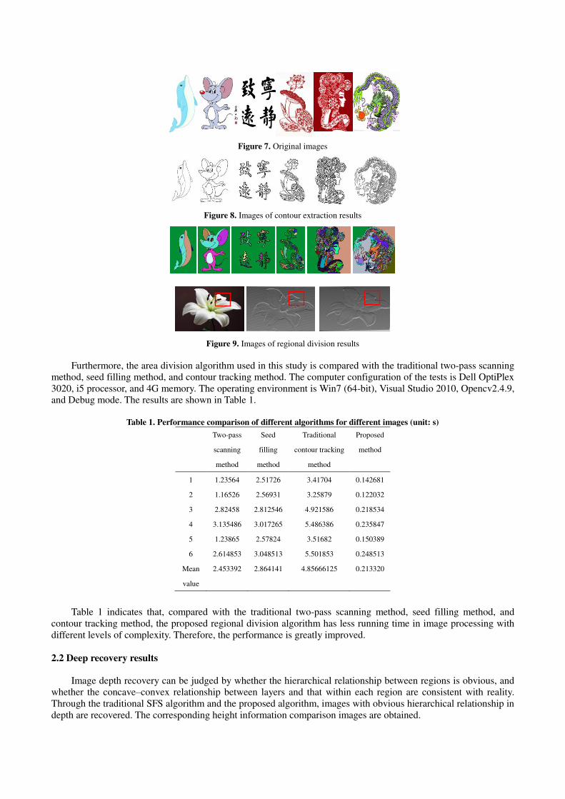
Figure 7. Original images
Figure 8. Images of contour extraction results
Figure 9. Images of regional division results
Furthermore, the area division algorithm used in this study is compared with the traditional two-pass scanning
method, seed filling method, and contour tracking method. The computer configuration of the tests is Dell OptiPlex
3020, i5 processor, and 4G memory. The operating environment is Win7 (64-bit), Visual Studio 2010, Opencv2.4.9,
and Debug mode. The results are shown in Table 1.
Table 1. Performance comparison of different algorithms for different images (unit: s)
Two-pass
scanning
method
Seed
filling
method
Traditional
contour tracking
method
Proposed
method
1 1.23564 2.51726 3.41704 0.142681
2 1.16526 2.56931 3.25879 0.122032
3 2.82458 2.812546 4.921586 0.218534
4 3.135486 3.017265 5.486386 0.235847
5 1.23865 2.57824 3.51682 0.150389
6 2.614853 3.048513 5.501853 0.248513
Mean
value
2.453392 2.864141 4.85666125 0.213320
Table 1 indicates that, compared with the traditional two-pass scanning method, seed filling method, and
contour tracking method, the proposed regional division algorithm has less running time in image processing with
different levels of complexity. Therefore, the performance is greatly improved.
2.2 Deep recovery results
Image depth recovery can be judged by whether the hierarchical relationship between regions is obvious, and
whether the concave–convex relationship between layers and that within each region are consistent with reality.
Through the traditional SFS algorithm and the proposed algorithm, images with obvious hierarchical relationship in
depth are recovered. The corresponding height information comparison images are obtained.

(a) Original image (b) Traditional algorithm (c) Proposed algorithm
Figure 10. Point cloud comparison images of the “treasure seal”
(a) Original image (b) Traditional algorithm (c) Proposed algorithm
Figure 11. Point cloud comparison images of the “Wen Emperor seal”
(a) Original image (b) Traditional algorithm (c) Proposed algorithm
Figure 12. Point cloud comparison images of the “lily pattern”
(a) Original image (b) Traditional algorithm (c) Proposed algorithm
Figure 13. Point cloud comparison images of the “peacock pattern”
Figures 10 and 11 show the recovery effect of the height values of the “treasure seal” and “Wen Emperor seal.” In the height information recovered by the traditional algorithm, the height value of the text is lower or higher than that of the base surface. This is inconsistent with the height value information obtained by the human
eye in the original image. Moreover, there is considerable noise effect and the surface is rough. The height
information recovered by the proposed algorithm is basically the same as that judged in the original image.
Furthermore, the noise points in the image are reduced, and the surface is relatively smooth.
Figure 12 shows the comparison of the depth recovery effect of the “lily pattern”. Both algorithms can recover the 3D contour of the image very well with less noise. In the image displayed by the point cloud, the light source is
located at the upper right of the image. The image is observed from the upper right to the bottom of the image. In
the traditional algorithm, the recovered depth of the lily in the image is generally lower than the plane where it is
located, and the relative height of each region does not match the actual situation. The target depth recovered by the
proposed algorithm is generally higher than the base surface where it is located. The relative depth between each
region is consistent with the actual situation, and the effect of recovered details is better. Figure 13 shows the
comparison of the height value recovery effect of the “peacock pattern.” In the height information obtained by the traditional algorithm, the overall height of the peacock is less than that of the plane where it is located, which does
not constitute the bas-relief model we expect. The height of the peacock obtained by the proposed algorithm is
higher than the plane where it is located, which is consistent with the actual situation. Moreover, the recovery effect
is better in the details of the peacock feathers.
2.3 3D reconstruction results
The point cloud data in Figures 9, 10, 11, and 12 are reconstructed in three dimensions and displayed through
OpenGL visualization. The reconstructed bas-relief models are shown in Figure 14. Figures 9 and 10 show the
bas-relief renderings of two different styles of seals. Their height information is obtained by the proposed algorithm.
Through the triangulation algorithm, the surface of the finally generated bas-relief model is smoother, with obvious
levels and accurate concave–convex relationship.

Figure 14. Relief renderings
Figures 12 and 13 show the simple images of animals and plants. Because the relative height difference
between each region is small and the details are more complicated, there is a certain degree of distortion in the later
triangulation algorithm. The algorithm needs to be further optimized in the later stage.
Figure 15. Original images of car logo
Figure 16. Relief renderings of car logo
In Figures 15 and 16, the original images of some car logos and the bas-relief model generated by the
proposed algorithm are, respectively, shown. In the actual image shown in Figure 14(a), the letters as well as the
texture of the image are higher than the plane where they are located. The proposed algorithm recovers the
corresponding height relationship effectively, and the surface of the generated bas-relief model is smooth. In Figure
15(b), the letters “PORSCHE,” the six antlers, and the surrounding frame have the maximum height values. The shield and the surrounding small region have relatively low height values. Moreover, the letters in the shield belong
to the engraving, and the height value is smaller than the plane where the shield is located. The horse in the shield
is slightly higher than the plane of the shield. The bas-relief effect generated by the proposed algorithm is
consistent with the actual situation. In Figure 15(c), the black part is line engraving, and the height value is less
than the surrounding plane. The generated bas-relief model conforms to the actual situation and has a smooth
surface. In Figure 15(d), the surrounding lines and letters are higher than the surrounding plane. The plane where
the letters are located, the inside and the plane of the cross, the inside and the region of the snake and the person are
lower. The crown is higher than the plane where it is located. The bas-relief model level height information
obtained by the proposed algorithm meets the actual situation. The shortcoming is that the original car logo is on a
curved surface, whereas the reconstructed relief model is a plane. This problem needs to be solved by further
(a)
(b) (c) (d)

research.
3 Conclusion
In this study, RGB monocular images were adopted as the research object and a method of bas-relief modeling
for RGB monocular images based on regional division was proposed. First, the edge contour of the RGB
monocular image was extracted and refined by the Gaussian difference algorithm of the tangential flow. Then,
regional division was performed on the RGB monocular image using the improved connected-domain labeling
algorithm. Subsequently, the SFS algorithm and human–computer interaction were used to generate a 3D point
cloud of each image region that meets the concave–convex characteristics of the bas-relief relief. Finally, the
bas-relief model of the RGB monocular image was obtained by reconstructing the triangular facets. This method
can automatically obtain the pixel height value of each image region in the image and adjust the concave–convex
relationship of each image region to realize a bas-relief model based on the RGB monocular image.
The proposed method has the following shortcomings, which require further research. In the process of using
the extracted image contour to perform regional division, a slight difference exists between the obtained result and
the actual situation at the contour; this affects the later image depth value recovery to a certain extent. Furthermore,
distortion may occur in the process of 3D reconstruction, which requires further research on the processing of point
cloud data to reconstruct a high-quality 3D surface.
Acknowledgment: The authors would like to thank the National Key Research and Development Program
(2018YFB1004901), Zhejiang Natural Science Fund Project (LQ19F020012),the Fundamental Research Funds of
Zhejiang Sci-Tech University(2020Q015).
References
Cignoni P, Montani C and Scopigno R. Computer-Assisted Generation of Bas-and High-Reliefs. Journal of Graphics Tools, 1997, 2(3): 15-28.
Weyrich T, Deng H, Barnes C, Rusinkiewicz S and Finkelstein A. Digital Bas-Relief from 3D Scenes. Acm Transactions on Graphics, 2007,
26(3): 32.
Zhang Y W, Zhou Y Q, Li X L,; Liu H and Zhang L L . Bas-Relief Generation and Shape Editing through Gradient-Based Mesh Deformation.
IEEE Transactions on Visualization and Computer Graphics, 2015, 21(3):328-338. Zhang Y W, Zhang C, Wang W and Chen Y, et al. Adaptive Bas-relief Generation from 3D Object under Illumination. Computer Graphics
Forum, 2016, 35(7):311-321.
Wei M , Tian Y , Pang W M , Charlie C. L. Wang, Pang M Y ,Wang J, Qin J and Pheng-Ann Heng. Bas-Relief Modeling from Normal Layers.
IEEE Transactions on Visualization and Computer Graphics, 2019, 25(4):1651-1665.
Kerber J, Tevs A, Belyaev A, Rhaleb Zayer and Hans-Peter Seidel. Real-time Generation of Digital Bas-Reliefs. Computer-Aided Design and
Applications, 2010, 7(4): 465-478.
Zhang L and Tong J. Real-time interaction based modeling method for 3D objects with relief-texture. Journal of Computer Applications
2017(8): 2302-2306.
Bay H, Ess A, Tuytelaars T and Van Gool L. Speeded-Up Robust Features (SURF). Computer Vision and Image Understanding, 2008, 110(3):
346-359.
Zhang G, Liu H, Dong Z, Jia J, Wong T and Bao H. Efficient Non-Consecutive Feature Tracking for Robust Structure-from-Motion. IEEE Trans
Image Process, 2015, 25(12): 5957-5970.
Frahm J M , Fite-Georgel P , Gallup D , Raguram T J , Wu C, Jen Y, Dunn E, Lazebnik B S and Pollefeys M. Building Rome on a Cloudless
Day// European Conference on Computer Vision. Springer, Berlin, Heidelberg, 2010.
Kyprianidis J E and Kang H. Image and Video Abstraction by Coherence-Enhancing Filtering. Computer Graphics Forum, 2011,
30(2):593-602.
Quéau, Yvain, Mélou, Jean, Castan F, Daniel C and Jean-Denis D. A Variational Approach to Shape-from-shading Under Natural Illumination.
2017. 33(2): 174–208.
Huang R and Smith W A P. Structure-preserving regularisation constraints for shape-from-shading. In Proc. the 13th International Conference
on Computer Analysis of Images and Patterns, Sept. 2009: 865-872.
Belhumeur P N, Kriegman D J and Yuille A L. The basrelief ambiguity. International Journal of Computer Vision, 2001, 35: 1040–1046.

Guodong L, Sha L and Jianxun L. A stereo vision tracking algorithm based on 3 -dimensional delaunay triangulation// Control & Decision
Conference. IEEE, 2016.
Jan G E, Sun C C, Tsai W C and Lin T H. An Shortest Path Algorithm Based on Delaunay Triangulation. Mechatronics IEEE/ASME
Transactions on, 2013, 19(2):660-666.
Soheil Mohajerani, Duruo Huang, Gang Wang, Seyed-Mohammad Esmaeil Jalali and Seyed Rahman Torabi. An efficient algorithm for
generation of conforming mesh for three-dimensional discrete fracture networks. Engineering Computations, 2018, 35(8): 202 -208.
Author information
Xinli WU (1987‒), female, lecturer. The research direction is virtual reality technology and human computer interaction. E-mail: [email protected]
Wenzhan YANG (corresponding author), male, profession. The main research direction is virtual reality technology.
E-mail: [email protected]
Jiali LUO, female, postgraduate. The main research direction is image processing. E-mail: [email protected]
Minxiong ZHANG, male, postgraduate. The main research direction is virtual reality technology. E-mail:


![SLAM and Depth Prediction arXiv:2004.10681v2 [cs.CV] 1 Aug 2020 · 2020. 8. 4. · Pseudo RGB-D for Self-Improving Monocular SLAM and Depth Prediction Lokender Tiwari1, Pan Ji 2,](https://static.fdocuments.in/doc/165x107/604de2f77fb7c30db709db16/slam-and-depth-prediction-arxiv200410681v2-cscv-1-aug-2020-2020-8-4-pseudo.jpg)