BAS Components - Innovative Fastening Solutionspdfs.findtheneedle.co.uk/111093-1818.pdfTHREAD...
20
BAS Components - Innovative Fastening Solutions BAS Components Proprietary Fastener Systems Flangeform TM AVK ® System Zero TM
Transcript of BAS Components - Innovative Fastening Solutionspdfs.findtheneedle.co.uk/111093-1818.pdfTHREAD...
BAS Components - Innovative Fastening Solutions
BAS Components
Proprietary Fastener SystemsFlangeformTM AVK® System ZeroTM

BAS ComponentsInnovative Fastening Solutions
Tackling the challenges of
reducing assembly costs, BAS
Components has earned an
enviable reputation for its fastener
products that are appropriate to a
wide range of materials, thicknesses
and applications. Working particularly
with the production demands of
the automotive industry, the BAS
Components fastener solutions offer
cost savings to fastener assembly
processes, particularly through the
introduction of automatic feed
into the die.
Within this brochure you will find details of the current range of BAS Components proprietary fasteners, with sample performance data and guidelines for their application and automatic feeding opportunities.
In addition to providing valuable cost savings, BAS Components fasteners are of benefit to designers by assuring reliability and a new degree of design freedom when working with aluminium, high strength materials, composites, plastics and stainless steels.
If you have any queries on the most suitable BAS Components fasteners or automatic feed for your particular application, our engineering support team is there to offer guidance and continued customer support.
2
Introduction
Contents
Flangeform High Strength Captive Fastener System . . . 3
Product Benefits . . . . . . . . . . . 4
Technical Advantages . . . . . . . 5
Technical DataNuts & Studs . . . . . . . . . . . . . . 6
Flangeform Studs . . . . . . . . . . 8
SRS Studs . . . . . . . . . . . . . . . . 8
Pulley Studs . . . . . . . . . . . . . . 8
Closed End Nuts . . . . . . . . . . . 8
Ball Studs . . . . . . . . . . . . . . . . 9
Flangeform Feed Systems . . . . 9
Flangeform Nut Feed . . . . . . 10
Flangeform Stud Feed . . . . . . 10
Feed Systems within Robotic Cells . . . . . . . . . . . . . 10
AVK High Strength Blind Threaded Fasteners . . . . . . 15
Why Use AVK? . . . . . . . . . . 16
Spinwall Technology . . . . . . . 17
AVK Inserts . . . . . . . . . . . . . . 18
AVK Studs . . . . . . . . . . . . . . 19
AVK Pneumatic Tools . . . . . . 20
System Zero . . . . . . . . . . . . 21
Extra Driveability & Security . 22
System Zero Data . . . . . . . . . 23
FLAN
GEFO
RM
FLANGEFORMHigh Strength Captive Fastener System
Ideal for thin gauge sheet materialAvailable in both nuts & studs in sizes from M3 to M12
TM

High Strength CaptiveFastener System
4
Flangeform
Flangeform is a high strength captive fastener system, ideal for thin
gauge sheet metal, available in both nuts and studs in sizes from
M3 to M12 and in equivalent unified ranges. With a proven track
record for product enhancement, combined with cost reduction,
Flangeform is widely accepted and used within the automotive,
appliance, electronic and general sheet metal industries.
Product Benefits
The benefits achieved through using Flangeform include:
● Reduced labour and process costs of up to 50%
● Optimum plant utilisation through automatic feeding
● Elimination of quality / rework problems
● One nut or stud per thread size reduces stockholding
● Utilisation in any press
Cost savings are particular to each application and our Sales Engineers andTechnicians will advise and assist you in achieving maximum inplace cost savings,while at the same time improving both your product and its quality.
Flangeform is manufactured under stringent QS9000 guidelines, moving toTS16949 to ensure product of the highest quality. After plating and prior to boxing,Flangeform is electronically inspected and sorted, to ensure that only correct andthreaded, uncontaminated product is shipped.
Our Design Engineers work closely with our customers to provide optimumfastening solutions. To allow full evaluation of Flangeform within your products, wewill carry out inplacement trials. This confidential service allows you fully to assessthe quality benefits and cost savings of Flangeform.
Flangeform Nuts in an automotive door.
Flangeform Nuts and Studs in anautomotive window regulator.
Flangeform Studs in driver’sairbag component.
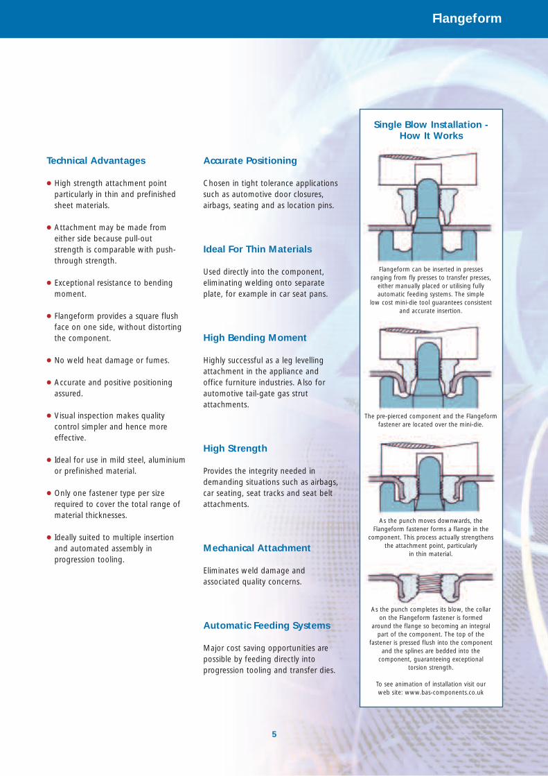
Single Blow Installation - How It Works
5
Flangeform
Technical Advantages
● High strength attachment pointparticularly in thin and prefinishedsheet materials.
● Attachment may be made fromeither side because pull-out strength is comparable with push-through strength.
● Exceptional resistance to bendingmoment.
● Flangeform provides a square flushface on one side, without distortingthe component.
● No weld heat damage or fumes.
● Accurate and positive positioningassured.
● Visual inspection makes qualitycontrol simpler and hence moreeffective.
● Ideal for use in mild steel, aluminiumor prefinished material.
● Only one fastener type per sizerequired to cover the total range ofmaterial thicknesses.
● Ideally suited to multiple insertionand automated assembly inprogression tooling.
Accurate Positioning
Chosen in tight tolerance applicationssuch as automotive door closures,airbags, seating and as location pins.
Ideal For Thin Materials
Used directly into the component,eliminating welding onto separateplate, for example in car seat pans.
High Bending Moment
Highly successful as a leg levellingattachment in the appliance and office furniture industries. Also forautomotive tail-gate gas strutattachments.
High Strength
Provides the integrity needed indemanding situations such as airbags,car seating, seat tracks and seat beltattachments.
Mechanical Attachment
Eliminates weld damage and associated quality concerns.
Automatic Feeding Systems
Major cost saving opportunities arepossible by feeding directly intoprogression tooling and transfer dies.
Flangeform can be inserted in presses ranging from fly presses to transfer presses,
either manually placed or utilising fully automatic feeding systems. The simple
low cost mini-die tool guarantees consistent and accurate insertion.
The pre-pierced component and the Flangeformfastener are located over the mini-die.
As the punch moves downwards, the Flangeform fastener forms a flange in the
component. This process actually strengthens the attachment point, particularly
in thin material.
As the punch completes its blow, the collar on the Flangeform fastener is formed
around the flange so becoming an integral part of the component. The top of the
fastener is pressed flush into the component and the splines are bedded into the
component, guaranteeing exceptional torsion strength.
To see animation of installation visit our web site: www.bas-components.co.uk
Technical Data
6
Flangeform
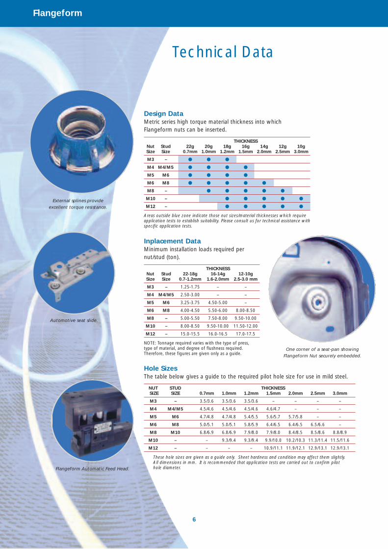
Inplacement DataMinimum installation loads required pernut/stud (ton).
THICKNESSNut Stud 22-18g 16-14g 12-10gSize Size 0.7-1.2mm 1.6-2.0mm 2.5-3.0 mm
M3 – 1.25-1.75 – –
M4 M4/M5 2.50-3.00 – –
M5 M6 3.25-3.75 4.50-5.00 –
M6 M8 4.00-4.50 5.50-6.00 8.00-8.50
M8 – 5.00-5.50 7.50-8.00 9.50-10.00
M10 – 8.00-8.50 9.50-10.00 11.50-12.00
M12 – 15.0-15.5 16.0-16.5 17.0-17.5
NOTE: Tonnage required varies with the type of press, type of material, and degree of flushness required.Therefore, these figures are given only as a guide.
Hole SizesThe table below gives a guide to the required pilot hole size for use in mild steel.
NUT STUD THICKNESS SIZE SIZE 0.7mm 1.0mm 1.2mm 1.5mm 2.0mm 2.5mm 3.0mm
M3 – 3.5/3.6 3.5/3.6 3.5/3.6 – – – –
M4 M4/M5 4.5/4.6 4.5/4.6 4.5/4.6 4.6/4.7 – – –
M5 M6 4.7/4.8 4.7/4.8 5.4/5.5 5.6/5.7 5.7/5.8 – –
M6 M8 5.0/5.1 5.0/5.1 5.8/5.9 6.4/6.5 6.4/6.5 6.5/6.6 –
M8 M10 6.8/6.9 6.8/6.9 7.9/8.0 7.9/8.0 8.4/8.5 8.5/8.6 8.8/8.9
M10 – – 9.3/9.4 9.3/9.4 9.9/10.0 10.2/10.3 11.3/11.4 11.5/11.6
M12 – – – – 10.9/11.1 11.9/12.1 12.9/13.1 12.9/13.1
These hole sizes are given as a guide only. Sheet hardness and condition may affect them slightly.All dimensions in mm. It is recommended that application tests are carried out to confirm pilot hole diameter.
Design DataMetric series high torque material thickness into whichFlangeform nuts can be inserted.
THICKNESSNut Stud 22g 20g 18g 16g 14g 12g 10gSize Size 0.7mm 1.0mm 1.2mm 1.5mm 2.0mm 2.5mm 3.0mm
M3 – v v v
M4 M4/M5 v v v v
M5 M6 v v v v
M6 M8 v v v v v
M8 – v v v v v
M10 – v v v v v
M12 – v v v v v
Areas outside blue zone indicate those nut sizes/material thicknesses which require application tests to establish suitability. Please consult us for technical assistance withspecific application tests.
External splines provide excellent torque resistance.
Automotive seat slide.
One corner of a seat-pan showingFlangeform Nut securely embedded.
Flangeform Automatic Feed Head.
7
Flangeform
MATERIALNuts: Steel BS EN ISO 10263-2.Finished nuts to conform to BS3692and/or ISO 898-2 Grade 8 MechanicalProperties. Other materials available. Studs: Steel BS EN ISO 10263-2.Finished studs to conform to ISO 898-1Grade 4.8 Mechanical Properties
OR
Steel BS EN ISO 10263-4. Finishedstuds to conform to ISO 898-1 Grade8.8 and above Mechanical Properties.Other grades available.
THREADStandard ISO Metric coarse pitch series, ISO
965/BS 3643-6g for studs and ISO 965/BS
3643-6H for nuts. Gauge tolerances in
accordance with ISO
1502 / BS 919 used to determine threadacceptability. After plating, threadsmust be capable of accepting a ‘Go’gauge of basic size. Other threadforms available.
FINISHZinc plate and chromate passivation toBS3382 Part 2. Plus dry lubrication.Other types and Hexavalent Cr6+ freecoatings also available.
IDENTIFICATIONAll nuts and studs to have strengthgrade markings in accordance withBS3692 and to carry manufacturer'sidentification.
N.B. The data given in this brochure is for generalguidance only and may vary with individualcircumstances. BAS Components Ltd and BASComponents Inc. will accept no liability arising outof misuse of this information.
Flangeform is a registered trade mark of BASComponents Ltd.
The Flangeform captive fastener is protected byworldwide patents.
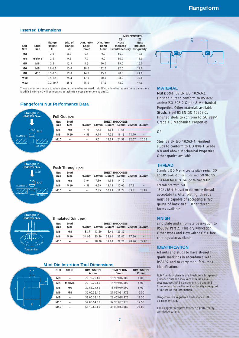
Inserted DimensionsMIN CENTRES
Z1 Z2Flange Dia. of Dim. From Dim. From Nuts Nuts
Nut Stud Height Flange Edge Bend Inplaced InplacedSize Size H ØF R min A min Simultaneously Singularly
M3 – 2.0 8.0 5.5 9.0 16.0 12.0
M4 M4/M5 2.5 9.5 7.0 9.0 16.0 13.0
M5 M6 3.8 12.5 8.5 10.0 19.0 16.0
M6 M8 4.0-5.0 15.0 10.0 12.0 22.0 19.0
M8 M10 5.5-7.5 19.0 14.0 15.0 28.5 24.0
M10 – 6.5-8.5 25.4 17.0 20.0 38.0 32.0
M12 – 10.2-10.7 35.0 25.0 27.0 48.0 44.0
These dimensions relate to when standard mini-dies are used. Modified mini-dies reduce these dimensions. Modified mini-dies will be required to achieve closer dimensions A and Z.
Simulated Joint (Nm)
Nut Stud SHEET THICKNESSSize Size 0.7mm 1.0mm 1.5mm 2.0mm 2.5mm 3.0mm
M6 M8 18.87 13.80 16.40 20.80 – –
M8 M10 34.95 35.40 38.60 35.40 37.60 –
M10 – – 78.00 79.00 78.20 78.20 77.80
Push Through (KN)
Nut Stud SHEET THICKNESSSize Size 0.7mm 1.0mm 1.5mm 2.0mm 2.5mm 3.0mm
M6 M8 3.94 7.39 11.94 14.12 – –
M8 M10 4.88 6.59 13.13 17.07 27.91 –
M10 – – 7.35 10.88 16.74 33.31 28.82
Pull Out (KN)
Nut Stud SHEET THICKNESSSize Size 0.7mm 1.0mm 1.5mm 2.0mm 2.5mm 3.0mm
M6 M8 4.79 7.43 12.04 11.55 – –
M8 M10 4.58 9.74 17.22 16.13 18.10 –
M10 – – 9.61 15.29 21.58 22.67 20.33
Strength inHR43F35 Steel
Strength inHR43F35 Steel
Strength inHR43F35 Steel
Torque (Nm)
Mini Die Insertion Tool DimensionsNUT STUD DIMENSION DIMENSION DIMENSION
A mm B mm C mm
M3 – 20.70/20.80 15.989/16.000 8.00
M4 M4/M5 20.70/20.80 15.989/16.000 8.00
M5 M6 27.55/27.65 18.989/19.000 8.00
M6 M8 32.00/32.10 21.963/21.975 12.50
M8 – 38.00/38.10 28.463/28.475 12.50
M10 – 54.00/54.10 37.963/37.975 12.50
M12 – 66.10/66.00 45.000/44.980 21.00
BOLT
MATERIAL
TEST BUSH
LOAD
BOLTMATERIAL
TEST BUSH
Flangeform Nut Performance Data
8
Flangeform
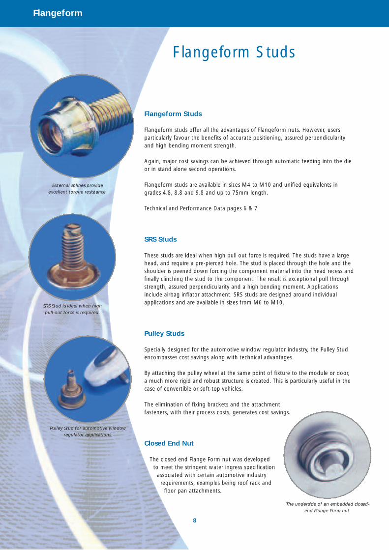
Flangeform Studs
Flangeform studs offer all the advantages of Flangeform nuts. However, usersparticularly favour the benefits of accurate positioning, assured perpendicularityand high bending moment strength.
Again, major cost savings can be achieved through automatic feeding into the dieor in stand alone second operations.
Flangeform studs are available in sizes M4 to M10 and unified equivalents ingrades 4.8, 8.8 and 9.8 and up to 75mm length.
Technical and Performance Data pages 6 & 7
SRS Studs
These studs are ideal when high pull out force is required. The studs have a largehead, and require a pre-pierced hole. The stud is placed through the hole and theshoulder is peened down forcing the component material into the head recess andfinally clinching the stud to the component. The result is exceptional pull throughstrength, assured perpendicularity and a high bending moment. Applicationsinclude airbag inflator attachment. SRS studs are designed around individualapplications and are available in sizes from M6 to M10.
Pulley Studs
Specially designed for the automotive window regulator industry, the Pulley Studencompasses cost savings along with technical advantages.
By attaching the pulley wheel at the same point of fixture to the module or door, a much more rigid and robust structure is created. This is particularly useful in thecase of convertible or soft-top vehicles.
The elimination of fixing brackets and the attachment fasteners, with their process costs, generates cost savings.
Closed End Nut
The closed end Flange Form nut was developed to meet the stringent water ingress specification
associated with certain automotive industry requirements, examples being roof rack and
floor pan attachments.
External splines provide excellent torque resistance.
SRS Stud is ideal when high pull-out force is required.
Pulley Stud for automotive windowregulator applications.
Flangeform Studs
The underside of an embedded closed-end Flange Form nut.
9
Flangeform
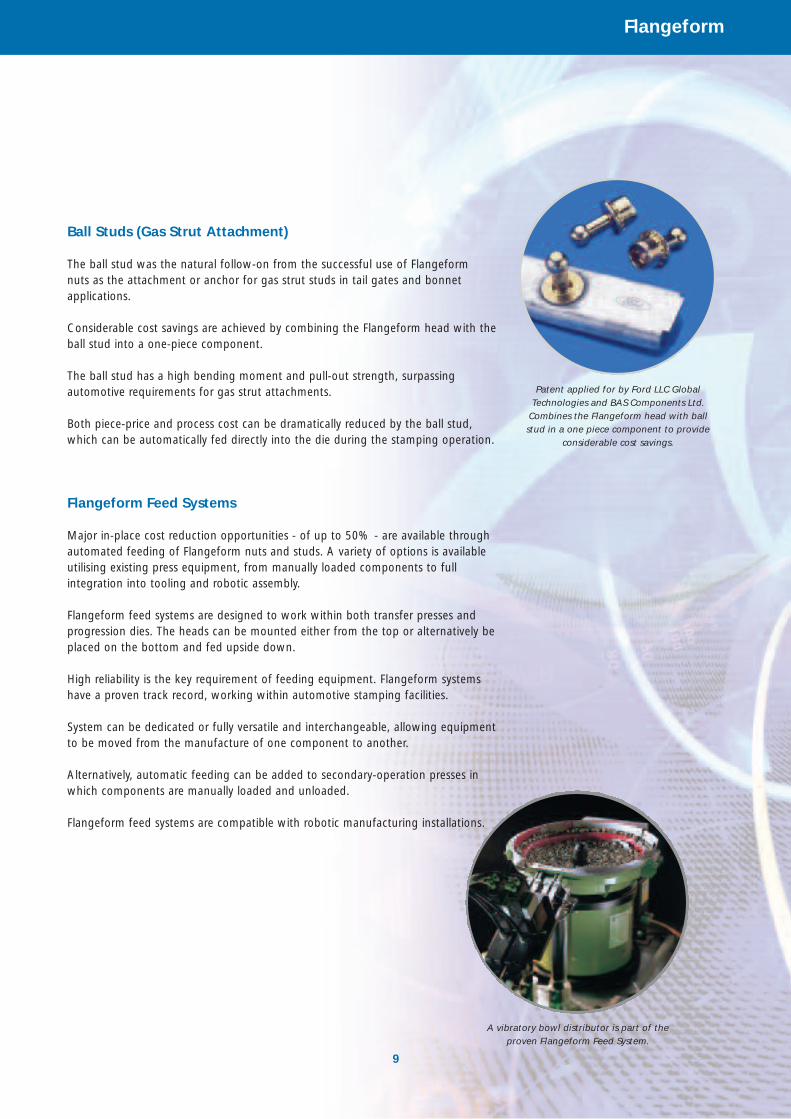
Ball Studs (Gas Strut Attachment)
The ball stud was the natural follow-on from the successful use of Flangeform nuts as the attachment or anchor for gas strut studs in tail gates and bonnetapplications.
Considerable cost savings are achieved by combining the Flangeform head with theball stud into a one-piece component.
The ball stud has a high bending moment and pull-out strength, surpassingautomotive requirements for gas strut attachments.
Both piece-price and process cost can be dramatically reduced by the ball stud,which can be automatically fed directly into the die during the stamping operation.
Flangeform Feed Systems
Major in-place cost reduction opportunities - of up to 50% - are available throughautomated feeding of Flangeform nuts and studs. A variety of options is availableutilising existing press equipment, from manually loaded components to fullintegration into tooling and robotic assembly.
Flangeform feed systems are designed to work within both transfer presses andprogression dies. The heads can be mounted either from the top or alternatively beplaced on the bottom and fed upside down.
High reliability is the key requirement of feeding equipment. Flangeform systemshave a proven track record, working within automotive stamping facilities.
System can be dedicated or fully versatile and interchangeable, allowing equipmentto be moved from the manufacture of one component to another.
Alternatively, automatic feeding can be added to secondary-operation presses inwhich components are manually loaded and unloaded.
Flangeform feed systems are compatible with robotic manufacturing installations.
Patent applied for by Ford LLC GlobalTechnologies and BAS Components Ltd.
Combines the Flangeform head with ballstud in a one piece component to provide
considerable cost savings.
A vibratory bowl distributor is part of the proven Flangeform Feed System.
10
Flangeform
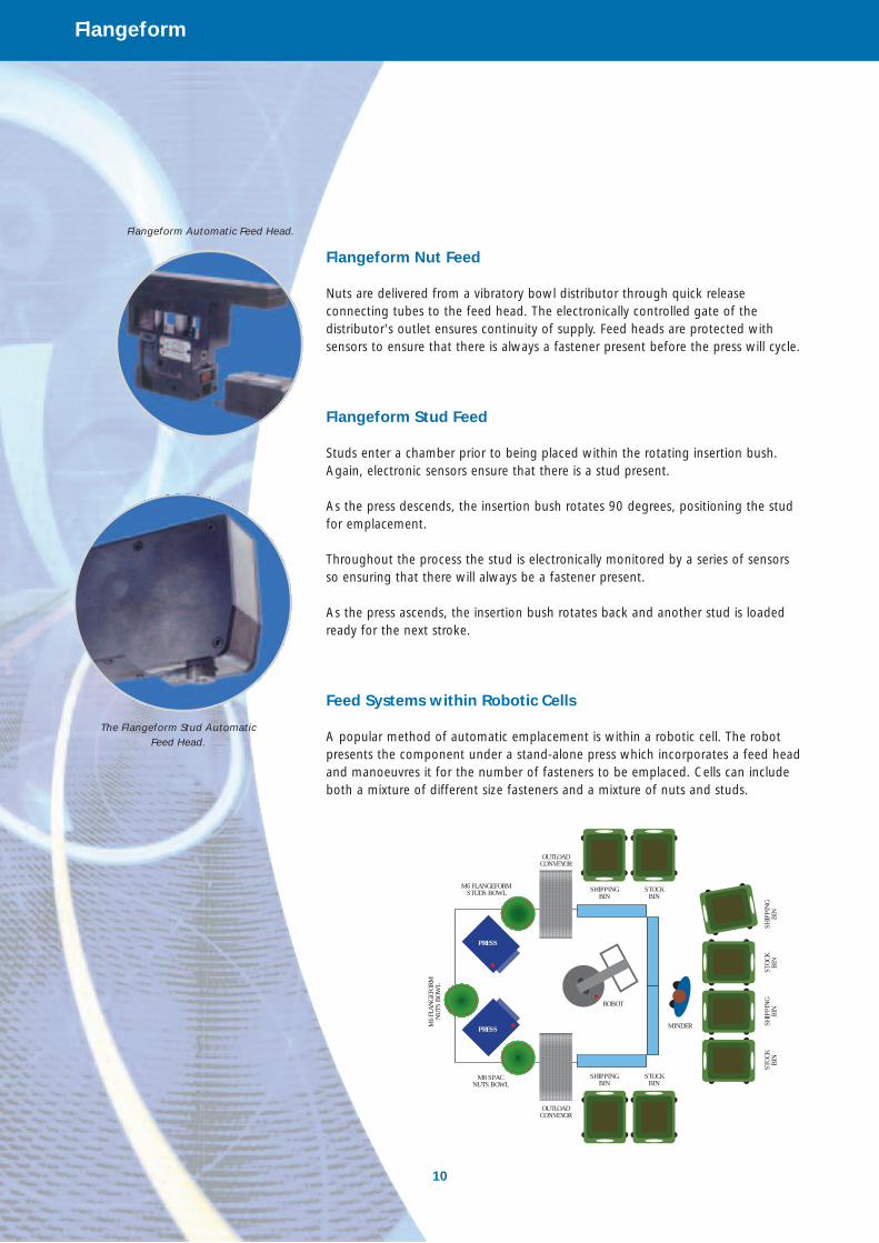
Flangeform Nut Feed
Nuts are delivered from a vibratory bowl distributor through quick releaseconnecting tubes to the feed head. The electronically controlled gate of thedistributor's outlet ensures continuity of supply. Feed heads are protected withsensors to ensure that there is always a fastener present before the press will cycle.
Flangeform Stud Feed
Studs enter a chamber prior to being placed within the rotating insertion bush.Again, electronic sensors ensure that there is a stud present.
As the press descends, the insertion bush rotates 90 degrees, positioning the studfor emplacement.
Throughout the process the stud is electronically monitored by a series of sensorsso ensuring that there will always be a fastener present.
As the press ascends, the insertion bush rotates back and another stud is loadedready for the next stroke.
Feed Systems within Robotic Cells
A popular method of automatic emplacement is within a robotic cell. The robotpresents the component under a stand-alone press which incorporates a feed headand manoeuvres it for the number of fasteners to be emplaced. Cells can includeboth a mixture of different size fasteners and a mixture of nuts and studs.
SHIPPING BIN
OUTLOAD CONVEYOR
M6 FLANGEFORM STUDS BOWL
ROBOT
MINDER
PRESS
PRESS
M8 SPAC NUTS BOWL
M6
FLAN
GEFO
RMN
UTS
BOW
L
OUTLOAD CONVEYOR
STOC
KBI
NSH
IPPI
NG
BIN
STOC
KBI
NSH
IPPI
NG
BIN
STOCK BIN
SHIPPING BIN
STOCK BIN
Flangeform Automatic Feed Head.
The Flangeform Stud Automatic Feed Head.
AV
K
AVKHigh Strength Blind Threaded Fasteners
Ideal for blind applications
®
Why Use AVK? Industry is Changing
16
AVK
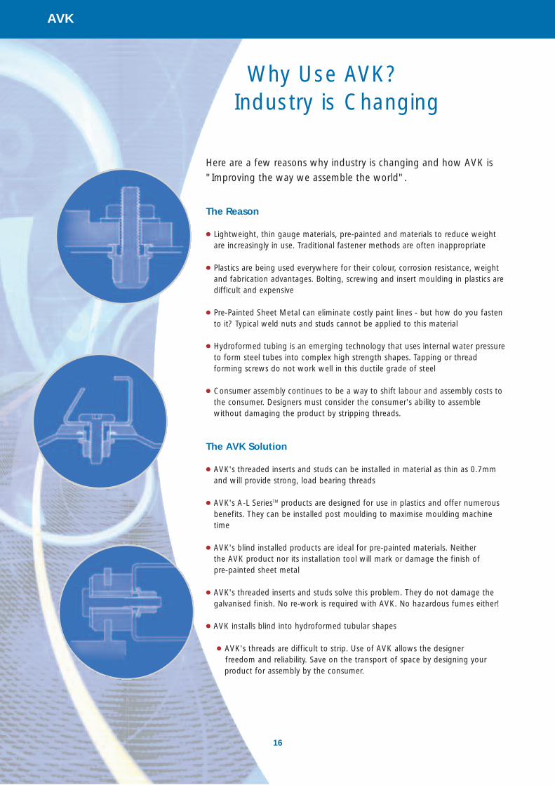
Here are a few reasons why industry is changing and how AVK is
"Improving the way we assemble the world".
The Reason
● Lightweight, thin gauge materials, pre-painted and materials to reduce weightare increasingly in use. Traditional fastener methods are often inappropriate
● Plastics are being used everywhere for their colour, corrosion resistance, weightand fabrication advantages. Bolting, screwing and insert moulding in plastics aredifficult and expensive
● Pre-Painted Sheet Metal can eliminate costly paint lines - but how do you fastento it? Typical weld nuts and studs cannot be applied to this material
● Hydroformed tubing is an emerging technology that uses internal water pressureto form steel tubes into complex high strength shapes. Tapping or threadforming screws do not work well in this ductile grade of steel
● Consumer assembly continues to be a way to shift labour and assembly costs tothe consumer. Designers must consider the consumer's ability to assemblewithout damaging the product by stripping threads.
The AVK Solution
● AVK's threaded inserts and studs can be installed in material as thin as 0.7mmand will provide strong, load bearing threads
● AVK's A-L SeriesTM products are designed for use in plastics and offer numerousbenefits. They can be installed post moulding to maximise moulding machinetime
● AVK's blind installed products are ideal for pre-painted materials. Neither the AVK product nor its installation tool will mark or damage the finish of pre-painted sheet metal
● AVK's threaded inserts and studs solve this problem. They do not damage thegalvanised finish. No re-work is required with AVK. No hazardous fumes either!
● AVK installs blind into hydroformed tubular shapes
● AVK's threads are difficult to strip. Use of AVK allows the designer freedom and reliability. Save on the transport of space by designing yourproduct for assembly by the consumer.
17
AVK
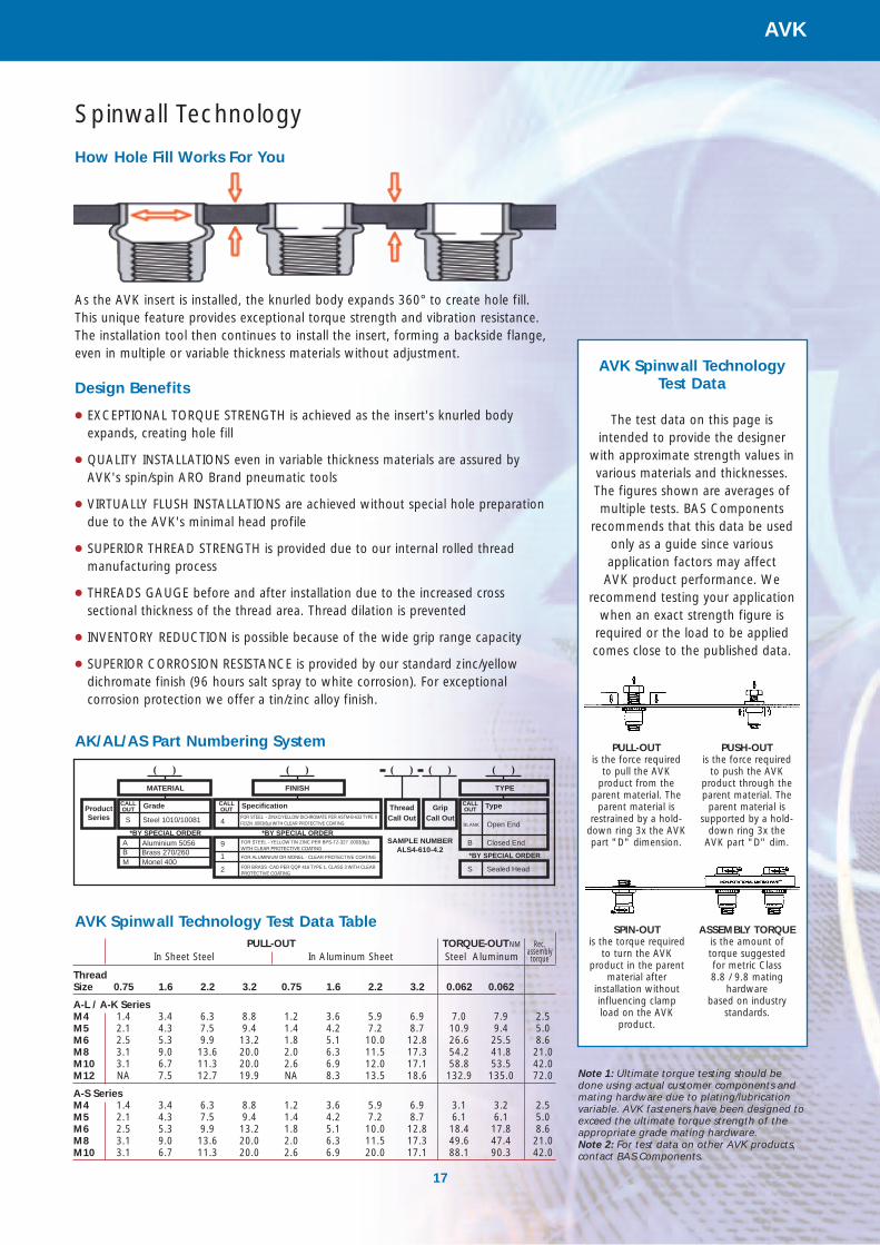
Spinwall Technology
How Hole Fill Works For You
As the AVK insert is installed, the knurled body expands 360° to create hole fill.This unique feature provides exceptional torque strength and vibration resistance.The installation tool then continues to install the insert, forming a backside flange,even in multiple or variable thickness materials without adjustment.
Design Benefits
● EXCEPTIONAL TORQUE STRENGTH is achieved as the insert's knurled bodyexpands, creating hole fill
● QUALITY INSTALLATIONS even in variable thickness materials are assured byAVK's spin/spin ARO Brand pneumatic tools
● VIRTUALLY FLUSH INSTALLATIONS are achieved without special hole preparationdue to the AVK's minimal head profile
● SUPERIOR THREAD STRENGTH is provided due to our internal rolled threadmanufacturing process
● THREADS GAUGE before and after installation due to the increased crosssectional thickness of the thread area. Thread dilation is prevented
● INVENTORY REDUCTION is possible because of the wide grip range capacity
● SUPERIOR CORROSION RESISTANCE is provided by our standard zinc/yellowdichromate finish (96 hours salt spray to white corrosion). For exceptionalcorrosion protection we offer a tin/zinc alloy finish.
MATERIAL FINISH TYPE
( )( ) ( )( )( )
FOR STEEL - YELLOW TIN ZINC PER BPS-TZ-327 .0003(8µ)WITH CLEAR PROTECTIVE COATING
FOR ALUMINIUM OR MONEL - CLEAR PROTECTIVE COATING
FOR BRASS -CAD PER QQP 416 TYPE 1, CLASS 3 WITH CLEAR PROTECTIVE COATING
Product Series
CALL OUT Grade CALL
OUT Specification CALL OUT Type
S Steel 1010/10081 4
9
1
2
ABM
Thread
Call OutGrip
Call Out
*BY SPECIAL ORDER *BY SPECIAL ORDER
*BY SPECIAL ORDER
FOR STEEL - ZINXC/YELLOW DICHROMATE PER ASTM-B-633 TYPE II FE/ZN .0003(8µ) WITH CLEAR PROTECTIVE COATING
Aluminium 5056Brass 270/260Monel 400
BLANK Open End
Closed End
Sealed Head
B
S
SAMPLE NUMBER ALS4-610-4.2
AK/AL/AS Part Numbering System
ThreadSize 0.75 1.6 2.2 3.2 0.75 1.6 2.2 3.2 0.062 0.062
A-L / A-K SeriesM4 1.4 3.4 6.3 8.8 1.2 3.6 5.9 6.9 7.0 7.9 2.5M5 2.1 4.3 7.5 9.4 1.4 4.2 7.2 8.7 10.9 9.4 5.0M6 2.5 5.3 9.9 13.2 1.8 5.1 10.0 12.8 26.6 25.5 8.6M8 3.1 9.0 13.6 20.0 2.0 6.3 11.5 17.3 54.2 41.8 21.0M10 3.1 6.7 11.3 20.0 2.6 6.9 12.0 17.1 58.8 53.5 42.0M12 NA 7.5 12.7 19.9 NA 8.3 13.5 18.6 132.9 135.0 72.0
A-S SeriesM4 1.4 3.4 6.3 8.8 1.2 3.6 5.9 6.9 3.1 3.2 2.5M5 2.1 4.3 7.5 9.4 1.4 4.2 7.2 8.7 6.1 6.1 5.0M6 2.5 5.3 9.9 13.2 1.8 5.1 10.0 12.8 18.4 17.8 8.6M8 3.1 9.0 13.6 20.0 2.0 6.3 11.5 17.3 49.6 47.4 21.0M10 3.1 6.7 11.3 20.0 2.6 6.9 20.0 17.1 88.1 90.3 42.0
PULL-OUT In Sheet Steel In Aluminum Sheet
TORQUE-OUTNM
Steel AluminumRec.
assemblytorque
SPIN-OUTis the torque required
to turn the AVK product in the parent
material afterinstallation withoutinfluencing clamp load on the AVK
product.
ASSEMBLY TORQUEis the amount of torque suggested for metric Class 8.8 / 9.8 mating
hardwarebased on industry
standards.
PULL-OUTis the force required
to pull the AVK product from the
parent material. Theparent material is
restrained by a hold-down ring 3x the AVKpart "D" dimension.
PUSH-OUTis the force required
to push the AVKproduct through theparent material. The
parent material issupported by a hold-
down ring 3x the AVK part "D" dim.
AVK Spinwall Technology Test Data
The test data on this page is intended to provide the designer
with approximate strength values invarious materials and thicknesses. The figures shown are averages ofmultiple tests. BAS Components
recommends that this data be usedonly as a guide since variousapplication factors may affect AVK product performance. We
recommend testing your applicationwhen an exact strength figure is
required or the load to be appliedcomes close to the published data.
Note 1: Ultimate torque testing should bedone using actual customer components andmating hardware due to plating/lubricationvariable. AVK fasteners have been designed toexceed the ultimate torque strength of theappropriate grade mating hardware. Note 2: For test data on other AVK products,contact BAS Components.
AVK Spinwall Technology Test Data Table
18
AVK
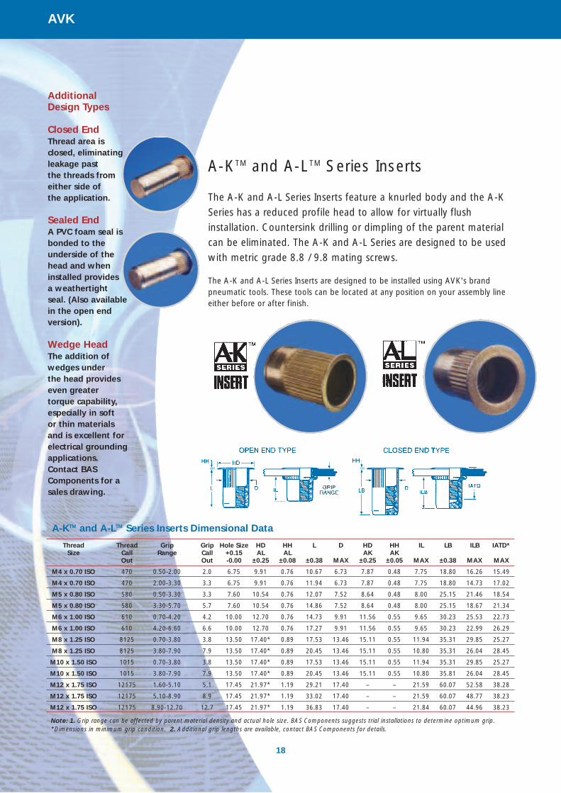
A-KTM and A-LTM Series Inserts
The A-K and A-L Series Inserts feature a knurled body and the A-K
Series has a reduced profile head to allow for virtually flush
installation. Countersink drilling or dimpling of the parent material
can be eliminated. The A-K and A-L Series are designed to be used
with metric grade 8.8 / 9.8 mating screws.
The A-K and A-L Series Inserts are designed to be installed using AVK's brandpneumatic tools. These tools can be located at any position on your assembly lineeither before or after finish.
A-KTM and A-LTM Series Inserts Dimensional Data
Thread Thread Grip Grip Hole Size HD HH L D HD HH IL LB ILB IATD*Size Call Range Call +0.15 AL AL AK AK
Out Out -0.00 ±0.25 ±0.08 ±0.38 MAX ±0.25 ±0.05 MAX ±0.38 MAX MAX
M4 x 0.70 ISO 470 0.50-2.00 2.0 6.75 9.91 0.76 10.67 6.73 7.87 0.48 7.75 18.80 16.26 15.49
M4 x 0.70 ISO 470 2.00-3.30 3.3 6.75 9.91 0.76 11.94 6.73 7.87 0.48 7.75 18.80 14.73 17.02
M5 x 0.80 ISO 580 0.50-3.30 3.3 7.60 10.54 0.76 12.07 7.52 8.64 0.48 8.00 25.15 21.46 18.54
M5 x 0.80 ISO 580 3.30-5.70 5.7 7.60 10.54 0.76 14.86 7.52 8.64 0.48 8.00 25.15 18.67 21.34
M6 x 1.00 ISO 610 0.70-4.20 4.2 10.00 12.70 0.76 14.73 9.91 11.56 0.55 9.65 30.23 25.53 22.73
M6 x 1.00 ISO 610 4.20-6.60 6.6 10.00 12.70 0.76 17.27 9.91 11.56 0.55 9.65 30.23 22.99 26.29
M8 x 1.25 ISO 8125 0.70-3.80 3.8 13.50 17.40* 0.89 17.53 13.46 15.11 0.55 11.94 35.31 29.85 25.27
M8 x 1.25 ISO 8125 3.80-7.90 7.9 13.50 17.40* 0.89 20.45 13.46 15.11 0.55 10.80 35.31 26.04 28.45
M10 x 1.50 ISO 1015 0.70-3.80 3.8 13.50 17.40* 0.89 17.53 13.46 15.11 0.55 11.94 35.31 29.85 25.27
M10 x 1.50 ISO 1015 3.80-7.90 7.9 13.50 17.40* 0.89 20.45 13.46 15.11 0.55 10.80 35.81 26.04 28.45
M12 x 1.75 ISO 12175 1.60-5.10 5.1 17.45 21.97* 1.19 29.21 17.40 – – 21.59 60.07 52.58 38.28
M12 x 1.75 ISO 12175 5.10-8.90 8.9 17.45 21.97* 1.19 33.02 17.40 – – 21.59 60.07 48.77 38.23
M12 x 1.75 ISO 12175 8.90-12.70 12.7 17.45 21.97* 1.19 36.83 17.40 – – 21.84 60.07 44.96 38.23
Note: 1. Grip range can be affected by parent material density and actual hole size. BAS Components suggests trial installations to determine optimum grip. *Dimensions in minimum grip condition. 2. Additional grip lengths are available, contact BAS Components for details.
Additional Design Types
Closed EndThread area is closed, eliminating leakage past the threads fromeither side of the application.
Sealed EndA PVC foam seal isbonded to theunderside of thehead and wheninstalled provides a weathertight seal. (Also availablein the open endversion).
Wedge HeadThe addition ofwedges under the head provides even greater torque capability,especially in soft or thin materials and is excellent forelectrical groundingapplications. Contact BASComponents for asales drawing.

19
AVK
A-STM Series Stud Profile
The A-S Series Stud profile offers a unique design advantage in
that, once installed, a threaded stud is left protruding from the
workpiece. Component parts can be located on the stud until final
assembly is accomplished with a mating nut. The A-S Series is an
ideal alternative to clinch or weld studs. The A-S Series is designed
to be used with metric PC8 non thread locking type nuts.
The A-S Series Stud is installed using AVK's ARO brand pneumatic tools. Thesetools can be located at any position on your assembly line. The A-S Series Stud canbe installed either before or after coating.
Design Benefits
● PROTRUDING STUD allows component parts to be located on the stud until final assembly is accomplished with a mating nut
● EXCEPTIONAL TORQUE STRENGTH is achieved as the stud's knurled bodyexpands, filling the hole
● QUALITY INSTALLATIONS even in variable thickness materials are assured byAVK's spin / spin ARO brand pneumatic tools
● ELIMINATE PAINT MASKING procedure as required with weld or clinch studs. The A-S Series Stud can be installed after painting
● SUPERIOR CORROSION RESISTANCE is provided by our standard zinc/yellowdichromate finish (96 hours salt spray to white corrosion). Alternative finishes are available
● AVAILABLE in steel 1010/1008 shell - Steel 1038 stem.
A-STM Series Stud Dimensional Data
Thread Thread Grip Grip Stud Lengths Hole Size HD HH L D ILSize Call Range Call ISL ISL ISL +0.15 ±0.25
Out Out Call Out Call Out Call Out -0.00 ±0.64* ±0.08 ±0.50 MAX MAX
M4 x 0.70 ISO 470 0.50-2.00 2.0 12.0 15.0 20.0 6.75 9.91 0.76 12.32 6.73 9.15
M4 x 0.70 ISO 470 2.00-3.30 3.3 10.7 13.7 18.7 6.75 9.91 0.76 13.59 6.73 9.15
M5 x 0.80 ISO 580 0.50-3.30 3.3 12.0 15.0 20.0 7.60 10.54 0.76 13.84 7.52 9.65
M5 x 0.80 ISO 580 3.30-5.70 5.7 9.6 12.6 17.6 7.60 10.54 0.76 16.64 7.52 9.65
M6 x 1.00 ISO 610 0.70-4.20 4.2 15.0 20.0 25.0 10.00 12.70 0.76 17.02 9.91 11.81
M6 x 1.00 ISO 610 4.20-6.60 6.6 12.6 17.6 22.6 10.00 12.70 0.76 19.56 9.91 11.81
M8 x 1.25 ISO 8125 0.70-3.80 3.8 16.0 22.0 28.0 13.50 17.40* 0.89 20.57 13.46 15.24
M8 x 1.25 ISO 8125 3.80-7.90 7.9 11.9 17.9 23.9 13.50 17.40* 0.89 23.50 13.46 14.10
M10 x 1.50 ISO 1015 0.70-3.80 3.8 20.0 25.0 30.0 13.50 17.40* 0.89 20.57 13.46 15.24
M10 x 1.50 ISO 1015 3.80-7.90 7.9 15.9 20.9 26.9 13.50 17.40* 0.89 23.50 13.46 13.60
Note: 1. Grip range can be affected by parent material density and actual hole size. BAS Components suggests trial installations to determine optimum grip. 2. Additional UNC fine threads are available, contact BAS Components for details. *Dimensions in maximum grip conditions.
Note: The ISLDimensionshown is theheight of theinstalled Stud atmax grip. Theheight of theStud willincrease if it isinstalled intothinnermaterial. Tocalculate actualISL use thisformula: Maxgrip-actualgrip + ISL=Actual grip
Threadspecifications:metric 6H/21per ASMEB1.13M
Pneumatic Tools Profile
20
AVK
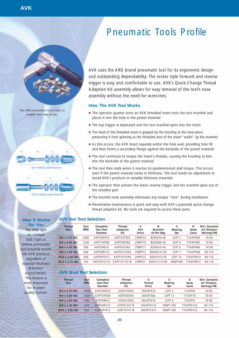
AVK uses the ARO brand pneumatic tool for its ergonomic design
and outstanding dependability. The rocker style forward and reverse
trigger is easy and comfortable to use. AVK’s Quick-Change Thread
Adaption Kit assembly allows for easy removal of the tool’s nose
assembly without the need for wrenches.
How The AVK Tool Works
● The operator quarter turns an AVK threaded insert onto the tool mandrel andplaces it into the hole in the parent material
● The top trigger is depressed and the tool mandrel spins into the insert
● The head of the threaded insert is gripped by the knurling at the nose-piece,preventing it from spinning as the threaded area of the insert "walks" up the mandrel
● As this occurs, the AVK Insert expands within the hole wall, providing hole filland then forms a secondary flange against the backside of the parent material
● The tool continues to torque the insert's threads, causing the knurling to biteinto the backside of the parent material
● The tool then stalls when it reaches its predetermined stall torque. This occurseven if the parent material varies in thickness. The tool needs no adjustment toinstall AVK's products in variable thickness materials
● The operator then presses the lower, reverse trigger and the mandrel spins out ofthe installed part
● The knurled nose assembly eliminates any torque "kick" during installation
● Preventative maintenance is quick and easy with AVK's patented quick-changethread adaption kit. No tools are required to access these parts.
AVK Nut Tool Selection
Thread Gun Complete Thread A B C D Min. DynamicSize RPM Gun Part Adaption Hex Mandrel Bearing Nose Air Pressure
Number Kit Drive 10 Per Bag Set Cone Settings PSI
M4 x 0.70 ISO 3000 AKPT30P470 AKPT470TAK 29NPT24 B3SH470-40 32PT 3 77AKPTM4 70-90
M5 x 0.80 ISO 1500 AKPT15P580 AKPT580TAK 29NPT10 B3SH580-45 32PT 4 77AKPTM5 70-90
M6 x 1.00 ISO 900 AKPT9P610 AKPT610TAK 29NPT11 B3SH610-40 32PT 6 77AKPTM6 70-90
M8 x 1.25 ISO 600 AKPT6P8125 AKPT8125TAK 29NPT12 B3SH8125-50 32PT 7 77AKPTM8 80-110
M10 x 1.50 ISO 600 AKPT6P1015 AKPT1015TAK 29NPT25 B3SH1015-50 32PT 10 77AKPTM10 80-110
M12 x 1.75 ISO 350 AKPT3P12175 AKPT12175CTA 29NPT27 B3SH12175-60 30NPT500 77AKPTM12 80-110
AVK Stud Tool Selection
Thread Gun Complete Thread A C D Min. DynamicSize RPM Gun Part Adaption Thread Bearing Nose Air Pressure
Number Kit Drive Set Cone Settings PSI
M4 x 0.70 ISO 3000 ASPT30P470 ASPT470TAK 29ASPT470 32PT 5 77ASPT8 70-90
M5 x 0.80 ISO 1500 ASPT15P580 ASPT580TAK 29ASPT580 32PT 12 77ASPT10 70-90
M6 x 1.00 ISO 900 ASPT9P610 ASPT610TAK 29ASPT610 32PT 8 77ASPT4 70-90
M8 x 1.25 ISO 600 ASPT6P8125 ASPT8125CTA 29ASPT8125 30NPT 500 77ASPT6125 80-110
M10 x 1.50 ISO 600 ASPT6P1015 ASPT1015CTA 29ASPT1015 30NPT 500 77ASPT8125 80-110
How It Works For You
The ARO spin on / torque
stall / spin toreverse pneumatic
tool properly installs the AVK products
regardless ofmaterial thickness
WITHOUTADJUSTMENT. This feature is
most important for in-plant
quality control.
The ARO pneumatic tool is light in weight and easy to use.
SYSTEM
ZERO
SYSTEM ZEROFor Extra Driveability and Security
Tamper proof screws ideal for security situations
TM

Extra Driveability & Security
22
System Zero
System Zero is a tamper resistant, external drive range of screws,
available in steel and stainless steel in sizes from M3 to M8 machine
and No.2 to No.14 self tapping.
The unique head-style requires a dedicated driver for installation and subsequent,authorised removal. In combination with the driver the head design gives hightorque transmission, which in turn generates high clamp loads.
These features make System Zero the number one choice where security is an issue.
System Zero Benefits
● Fit and forget
● Virtually 100% security without associated removal tool
● High torque acceptance without 'cam-out'
● Non-slip external drive.
System Zero Is Specified By Engineers and Designers For Its Unique Blend Of Features
● Effective tamper-resistant design
● Robust performance
● External drive
● High clamp load
● Exceptional drive capabilities
● Range of thread styles available.
Internal drive screws have a weakness of 'cam out' as increased torque is applied,resulting in slippage, potential damage to the components to be fastened andvariable clamp load.
System Zero's unique external drive greatly reduces the chance of slippage andresulting damage, while achieving a high clamp load.
Because it is robust, it is ideal for the high performance requirements associatedwith security.
When System Zero screws are recessed in a component, it is virtually impossible toremove them without an associated driver.
System Zero screws are available in a variety of thread styles.
R
Optional slot Delete to make tamper proof
Driving groove is semi-circle
centred on head diameter
Six grooves spread load - Speed driver engagement
Head radius 'R' tangent to arc
at point of driver contact
Point of contact max distance from centre
Required force direction
Actual force directionZero drive
angle 0°
System ZERO
Required force direction
Actual force
direction
60°
HEX head
HEAD
DRIVER
X
X
5°45'26°
CROSS RECESS
X
X
SYSTEM ZERO
0° Cam out angle
Cam out angle
Increase driver angle, increase cam out
BAS ComponentsInnovative Fastening Solutions
Tackling the challenges of
reducing assembly costs, BAS
Components has earned an
enviable reputation for its fastener
products that are appropriate to a
wide range of materials, thicknesses
and applications. Working
particularly with the production
demands of the automotive industry,
the BAS Components fastener
solutions offer cost savings to fastener
assembly processes, particularly through
the introduction of automatic feed
into the die.
Within this brochure you will find details of thecurrent range of BAS Components proprietaryfasteners, with sample performance data andguidelines for their application and automaticfeeding opportunities.
In addition to providing valuable cost savings,BAS Components fasteners are of benefit todesigners by assuring reliability and a newdegree of design freedom when working withaluminium, high strength materials,composites, plastics and stainless steels.
If you have any queries on the most suitableBAS Components fasteners or automaticfeed for your particular application, ourengineering support team is there to offerguidance and continued customersupport.
2
Introduction
Contents
Flangeform High StrengthCaptive Fastener System . . . 3
Product Benefits . . . . . . . . . . . 4
Technical Advantages . . . . . . . 5
Technical DataNuts & Studs . . . . . . . . . . . . . . 6
Flangeform Studs . . . . . . . . . . 8
SRS Studs . . . . . . . . . . . . . . . . 8
Pulley Studs. . . . . . . . . . . . . . . 8
Closed End Nuts . . . . . . . . . . . 8
Ball Studs . . . . . . . . . . . . . . . . 9
Flangeform Feed Systems . . . . 9
Flangeform Nut Feed. . . . . . . 10
Flangeform Stud Feed . . . . . . 10
Feed Systems within Robotic Cells . . . . . . . . . . . . . 10
SPAC Nut . . . . . . . . . . . . . . . 11
Self Pierce And Clinch . . . . . . 12
How the SPAC Nut InstallationProcess Works & Data . . . . . . 13
SPAC Nut Feed Systems. . . . . 14
Feed Systems within Robotic Cells . . . . . . . . . . . . . 14
AVK High Strength BlindThreaded Fasteners . . . . . . 15
Why Use AVK? . . . . . . . . . . . 16
Spinwall Technology . . . . . . . 17
AVK Inserts . . . . . . . . . . . . . . 18
AVK Studs . . . . . . . . . . . . . . . 19
AVK Pneumatic Tools. . . . . . . 20
System Zero . . . . . . . . . . . . 21
Extra Driveability & Security . . 22
System Zero Data . . . . . . . . . 23 23
System Zero
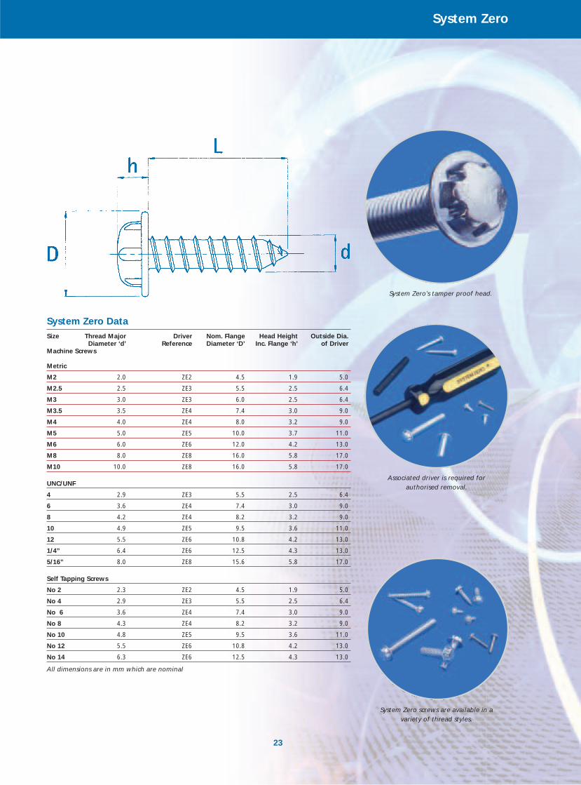
System Zero DataSize Thread Major Driver Nom. Flange Head Height Outside Dia.
Diameter ‘d’ Reference Diameter ‘D’ Inc. Flange ‘h’ of DriverMachine Screws
Metric
M2 2.0 ZE2 4.5 1.9 5.0
M2.5 2.5 ZE3 5.5 2.5 6.4
M3 3.0 ZE3 6.0 2.5 6.4
M3.5 3.5 ZE4 7.4 3.0 9.0
M4 4.0 ZE4 8.0 3.2 9.0
M5 5.0 ZE5 10.0 3.7 11.0
M6 6.0 ZE6 12.0 4.2 13.0
M8 8.0 ZE8 16.0 5.8 17.0
M10 10.0 ZE8 16.0 5.8 17.0
UNC/UNF
4 2.9 ZE3 5.5 2.5 6.4
6 3.6 ZE4 7.4 3.0 9.0
8 4.2 ZE4 8.2 3.2 9.0
10 4.9 ZE5 9.5 3.6 11.0
12 5.5 ZE6 10.8 4.2 13.0
1/4” 6.4 ZE6 12.5 4.3 13.0
5/16” 8.0 ZE8 15.6 5.8 17.0
Self Tapping Screws
No 2 2.3 ZE2 4.5 1.9 5.0
No 4 2.9 ZE3 5.5 2.5 6.4
No 6 3.6 ZE4 7.4 3.0 9.0
No 8 4.3 ZE4 8.2 3.2 9.0
No 10 4.8 ZE5 9.5 3.6 11.0
No 12 5.5 ZE6 10.8 4.2 13.0
No 14 6.3 ZE6 12.5 4.3 13.0
All dimensions are in mm which are nominal
Associated driver is required for authorised removal.
System Zero’s tamper proof head.
System Zero screws are available in a variety of thread styles.
United KingdomBAS Components LtdCramptons RoadSevenoaks Kent TN14 5DS
Tel: +44 (0) 1732 450011/741881Fax: +44 (0) 1732 455884/743166
USABAS Components Inc1100 North Meridian RoadYoungstownOhio 44515
Tel: 330 793 9650Fax: 330 793 9620
FranceBAS ComponentsTT electronics France17 Rue Du Kefir94567 ORLYCEDEXFrance
Tel: +33 14 51 23 877Fax: +33 14 51 23 879
GermanyBAS ComponentsTT electronics GermanyKirchberg 5940699 ErkrathGermany
Tel: +0049 (0)2104 145154Mobile: +0049 (0)172 265 6946Fax: +0049 (0)2104 145153
BAS Components Engineering Service
Our engineers are experienced in working with customers to arrive at both the ideal technical fastening solution and also the most cost-effective.
Skilled in emplacements, testing, and feeding systems, we offer our customers a full service provision in evaluating applications. This allows customers to evaluate technical and economic advantages without incurring costs.
When the application goes ahead our engineers support the customer throughout, from prototype build to launch, and continuing beyond with feed system servicing.
The BAS team of sales and application engineers will advise you on the most cost effective joint design or your fastener requirement.
Feeding systems are designed, manufactured, commissioned and serviced by our own systems engineers.
Your Guarantee
Manufacturers worldwide have come to rely on the quality, reliability and cost-effectiveness of BAS Components range of proprietary fasteners.
With accreditation to QS9000, ISO9001 and moving towards TS16949, BAS Components has the design, production and engineering capabilities to meet customers’ total requirements for fastening solutions.
A subsidiary of TT electronics PLC.
Flangeform is protected by world wide patents.Flangeform and the Flangeform logo are registered trademarks of BAS Components Ltd.
SPAC is protected by world wide patents.SPAC is a trademark of RB&W Corporation Inc.SPAC Nut is manufactured under licence from RB&W Corporation Inc.
AVK is protected by world wide patents.AVK is a world wide trademark of AVK Manufacturing Inc.
System Zero is protected by world wide patents.System Zero is a registered trademark of BAS Components Ltd.
[email protected] www.bas-components.co.uk