
Barzan PJ Assignment
37
Site Assignment From 05-May-2012 to 08-May-2013 1 Barzan Onshore EPC Project Muhammad Ahmed Rana Piping Design Engineer Descon Integrated Projects Pvt. Ltd.
-
Upload
muhammad-ahmed-rana -
Category
Documents
-
view
87 -
download
1
Transcript of Barzan PJ Assignment
Site Assignment From 05-May-2012 to 08-May-2013
1
Barzan Onshore EPC Project
Muhammad Ahmed RanaPiping Design Engineer
Descon Integrated Projects Pvt. Ltd.

Presentation Outlines
2
1. Barzan Project Overview2. Spoolgen Operations3. CMS and Spoolgen Interface4. YS/FS Change Sheets5. Site Drawing’s Revision Work6. Field Engineering Support7. Project Pictures

3
1. BARZAN PROJECT OVERVIEW

1. Barzan Project Overview
4
Total No. of Lines: 50,300 Total Project Dia Inches: 3,600,000 Total No. of Equipments: 1,100
DESCON Scope No. of Lines: 10,600 Total Dia Inches 690,000

Construction Subctractors
5
CCC NSH
DESCON QCON
JGC
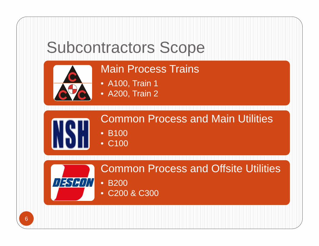
Subcontractors Scope
6
Main Process Trains• A100, Train 1• A200, Train 2
Common Process and Main Utilities • B100• C100
Common Process and Offsite Utilities• B200• C200 & C300

Overall Plot Plan
7

Descon Scope Areas
8
Sour Water Area MEG Regeneration Condensate Stabilization (Compressor Area) Flare K.O Effluent Treatment Inlet Facilities Area (Slug Catcher) Cooling Tower Area Flare Main Sea Water Line (42”-FRP) 86” Cooling Water Line

9
2. SPOOLGEN OPERATIONS

Organogram of Spoolgen and My Responsibilities
10
DESCON Planning&
FEDC

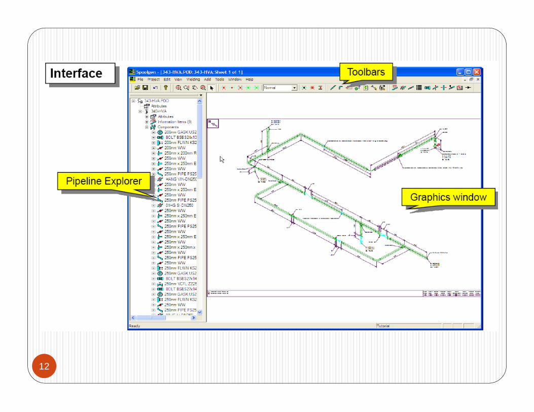
About Spoolgen
11
Intergraph Software for Automatic Spooling and Joint Marking
Input File is IDF File generated from PDS or PCF File generated from SP3D Software
The outputs CAD Files (Spool drawings for Fabrication) Weld/Joint Information Material data for accurate material allocation Site Assembly/Bolting Information
12

Advantages
13
Planning and BOQ
Reduces Manhour
Better Material
Allocation and Control

Spool Drawing Preparation and Issuance
14
Piping Isometric Review and Joint Marking Preparation of Input Data for Spoolgen Software Spoolgen Operations (FW Marking, Sheet Split) Output files Generation (CAD and Text data) CAD Drawing Along with Data issued to Subcon Maintaining Index and Issuance Control Sheets
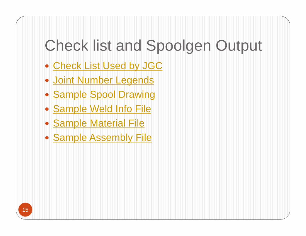
Check list and Spoolgen Output
15
Check List Used by JGC Joint Number Legends Sample Spool Drawing Sample Weld Info File Sample Material File Sample Assembly File

16
3. CMS AND SPOOLGEN INTERFACE

Construction Management System
17
JGC In-house software for complete Construction Management
CMS
MateralControl
Test Pack Control
FS Control System
Welding Control
ContructionPlanning

18
3D (PDS etc.)
MACS
REQ
PCOM
ETRS / MTCS
SPOOLGEN
CMS
REQ
PO
Spool Piece wise Material Data (LOM)
Weld Joint Data
Assembly Data
PO/Shipping Data
(MSR Data)
E(3D) C(CMS)
Spool Piece Dwg
Spool Dwg
P(PMS)
ISO wise Material Data(LOM)

19
4. YS/FS CHANGE SHEETS

YS/FS CHANGE SHEETS
20
Change Sheets Preparation for all Isometrics (Engineering) Revisions
Automatically generated from CMS Input for YS is “*.b” files Input for FS is Manually/Site Mark-up All spool drawings are updated as per the isometric
revisions Joint Additions, deletions, and cut and re-welds YS Revision Check List Sample YS sheet YS/FS Tracking Sheet Finally to DHT for Issuance to Subcon.

21
5. Site Spool Drawings Revisions Work

Site Revisions Work
22
All Changes due to site work other than Engineering Change
Joint Change Request Form (JCRF) Shop Fabrication Errors Site Installation Errors Joint Category Change Change due to Construction Sequence (Hydrotesting) Cut and Re-weld due to RT Failure Joint added due to Random Pipe Length Change due to seam Weld orientation
Sample Site Revision Drawings
23
Sample 1, Hydro Testing Sample 2, Change Due To Random Pipe Length

24
6. Field Engineering Support

Plate Thickness for Hydrotesting
25
Blind for Hydrotesting of 36” Line Mating Flange = 36” 600# ASME B16.47 Ser. B Material A36 Design Pressure = 126.3 barg
Blind Thickness as per ASME Sec VIII Comes out to be 145MM

PAD Overlapping with Seam
26
For 52” &56” lines, R.L received 9M instead of plan 11M
Drawings need to be revised as there were additional joints
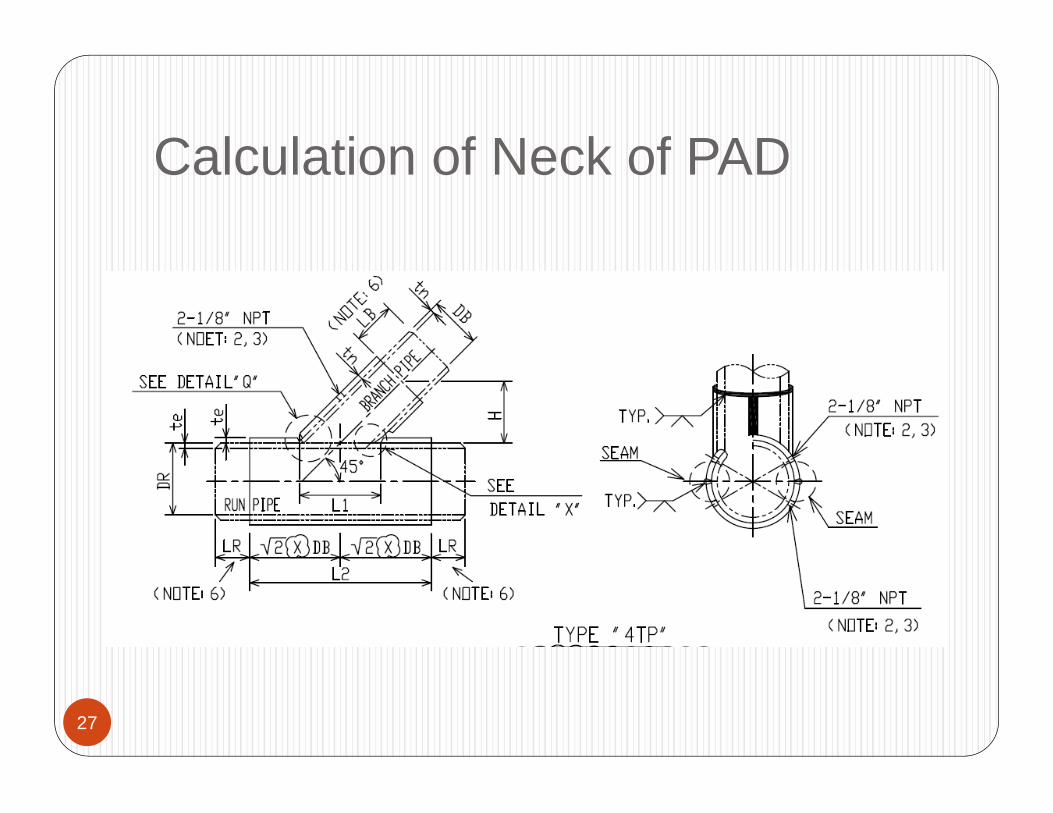
Calculation of Neck of PAD
27

Double PAD for AIV Lines
28

FTR (Field Trouble Record) Issuance
29
FTR was issued by Subcon to JGC for any kind of problem related to Fabrication/installation of Piping
Sample FTR

Field Trouble Isometrics-1
30

Field Trouble Isometrics-2
31
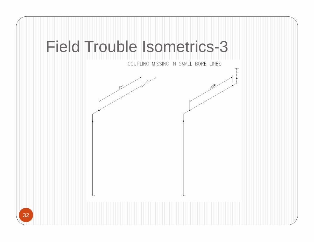
Field Trouble Isometrics-3
32
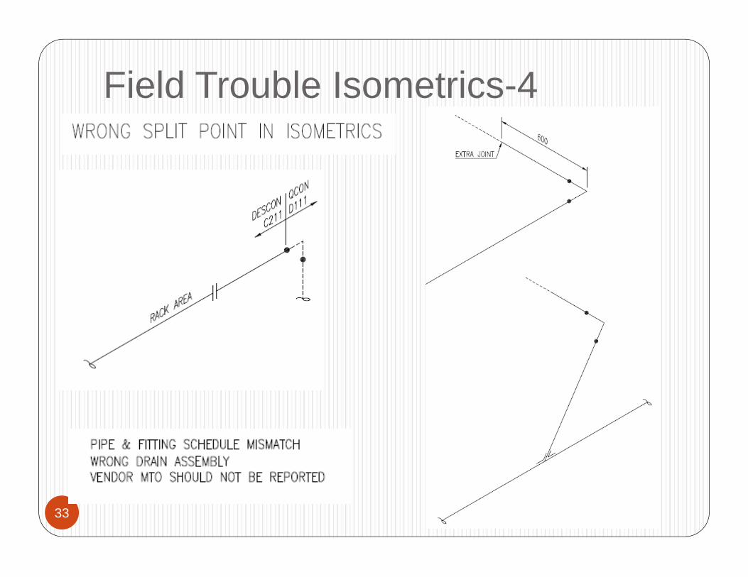
Field Trouble Isometrics-4
33

Spool dwg Hold and Release
34
Spool Fabrication, Installation, Material Issuance, and every thing got hold for YS Drawings
So if there are many such drawings Shop cannot proceed Fabrication
Welders/Fabricators can sit idle in severe conditions if there are too many revisions viz. not acceptable in any case.
Since all changes are not related to shop fabrication, so shop can proceed fabrication for such cases
So, we provided information of spools that shop can proceed fabrication without any impact by revision

Spool dwg Hold and Release
35
Spool Drawing With Impact on Fabrication Spool Drawing With No Impact on Fabrication

36
7. Project Pictures (FOLDER)

37
Thank you for Participation


![PJ-700 Series - Brother Romania · PJ-722 PJ-723 PJ-762 PJ-763 PJ-773 203 x 200dpi 300 x 300dpi Direct thermal Ave.: 8ppm (under Brother standard environment) [1] Manual paper feed](https://static.fdocuments.in/doc/165x107/6011125cfd957b084207e3b2/pj-700-series-brother-romania-pj-722-pj-723-pj-762-pj-763-pj-773-203-x-200dpi.jpg)