ATLAS Review and Main Results Ryszard Stroynowski Southern Methodist University
T H E A R C H I V E O F M E C H A N I C A L E N G I N E E R I N G
VOL. LVII 2010 Number 3
10.2478/v10180-010-0015-xKey words: bolt joint, special finite elements, stiffness characteristics
BARTŁOMIEJ ŻYLIŃSKI∗, RYSZARD BUCZKOWSKI ∗
ANALYSIS OF BOLT JOINT USING THE FINITE ELEMENTMETHOD
A numerical analysis of the initially clamped bolt joint subject to the workingpressure is presented in the paper. Special, hexahedral 21- and 28-node isoparametricfinite elements have been employed to model the contact zone. In this model, onetakes into account loading due to the working pressure in the gap between the gasketand the flange arising as an effect of the progressing joint opening, what has notbeen considered in recent papers. Nonlinear stiffness characteristics of the bolt and theflange with the gasket are developed. Working pressure corresponding to the criticalbolt force resulting in the joint leakage (complete opening between the gasket andthe flange) is determined. FE computational results are compared with the availableexperimental results. The numerical results are presented using the authors’ owngraphical postprocessor.
1. Subject of analysis
Flange joints are commonly used, e.g. in pipeline connections. Variousaspects concerning approximate analytical calculations in a one-dimensionalform, properties and servicing of the bolt joints are described in [1,2,3].Osgood [4], Motosh [5], Shigly and Mischke [6] discussed in their worksthe flange connections in which the contact surfaces, which include the areabetween the flanges and the gasket, are assumed to be constant and withoutfriction between the flange and the gasket. The nonlinear force-deflectionbehaviour of the connection was presented in Junker [7] and Bickford [8]. Inthe papers by Zahavi and others [9,10,11], one can find numerical analysesbased on the finite element method that make use of commercial finite ele-
∗ Maritime University of Szczecin, Division of Computer Methods, H. Poboznego11, 70-507 Szczecin, Poland; E-mail: [email protected] (B.Ż) [email protected] (R.B)
Brought to you by | Biblioteka Glowna UniwersytetuAuthenticated
Download Date | 11/17/14 10:36 AM
276 BARTŁOMIEJ ŻYLIŃSKI, RYSZARD BUCZKOWSKI
ment packages ANSYS and NASTRAN [9,10,11], which take into accountthe nonlinear stiffness characteristics of the bolt joints.
The flange joints belong to the group of initially-clamped joints where thebolts are pre-stressed before applying working loading. The initial clamp isimportant for the joint behaviour, especially in pressure vessels and pipelines.
The joint presented in Fig. 1 was analysed numerically. The geometry,material properties, the value of the initial force of 15 kN and dimensionsof the example were taken from Sawa, Higurashi and Akagawa [12]. It wasalso considered in ABAQUS Example Problems Manual where the stickingcontact conditions were assumed in all contact areas. Here, this solution isphysically more realistic, since gaskets separate from their neighbouring partswhen subjected to tensile loading.
Selection of finite elements and control of the contact condition by thenodal contact forces must result in positive equivalent nodal forces. Adoptingthe standard 20-node (C3D20 or C3D20R according to nomenclature takenfrom ABAQUS) or 32-node hexahedral elements results in equivalent nodalforces of both compressive and tensile type. The corner nodal forces becomenegative and the midside ones are positive. Thus, the elements do not rep-resent the contact phenomenon properly. Because the standard second-orderbrick elements of the Serendipity family can not be used in modelling of thecontact zone, special 21- or 28-node hexahedral elements were employed inthe present analysis [13,14].
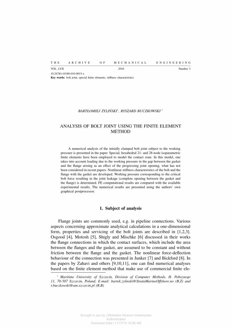
Fig. 1. Bolt joint (22.5 degrees sector)
Brought to you by | Biblioteka Glowna UniwersytetuAuthenticated
Download Date | 11/17/14 10:36 AM

ANALYSIS OF BOLT JOINT USING THE FINITE ELEMENT METHOD 277
The dimensions and shape of the joint comply with the following stan-dards: JIS B (Japanese standard) and ANSI B 16.5 (American standard). Thejoint was investigated experimentally at a real research stand [12].
Due to the cyclic symmetry of the joint, a sector of 22.5 degrees wasanalysed numerically.
In the basic variant, the joint is composed of (Fig.1):– two flanges having internal diameter of 50 mm and external diameter
of 165 mm each,– gasket of internal diameter of 50 mm and external diameter of 108
mm and thickness of 3 mm or 5 mm,– 8 bolts located at the pitch diameter of 130 mm.The flanges used in the experiment were made of steel (for structural
use, S45, acc. to JIS).Bolts with thread M16 were made of chrome-molybdenum steel. The
bolt shaft diameter (length of 20 mm) was reduced to 14 mm to locatestrain gauge. In the basic variant, an aluminium gasket was applied (Al.-H,according to JIS). The material constants were:
– for the flange: E = 206000 MPa, ν = 0.3,– for the bolts: E = 206000 MPa, ν = 0.3,– for the gasket: E = 68700 MPa, ν = 0.3.After the flanges were assembled together with the gasket, each of the
bolts was pre-tensioned with the force of F = 15 kN.
2. Computational model
2.1. Finite element model
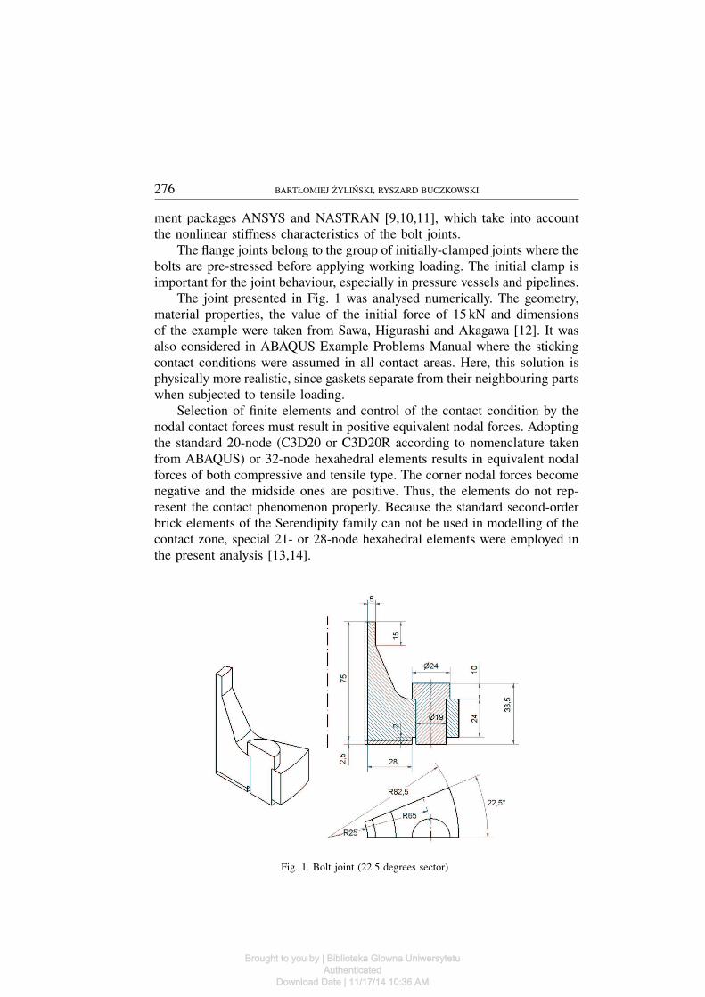
According to the above-described assumptions (cyclic symmetry), wedeveloped a model corresponding to the sector of 22.5 degrees of the boltjoint. The model presented in Fig. 2 is composed of:
– the flange (red colour – 3425 20-node finite elements beyond the con-tact zone, and 21-node (denotation: C3D21 [13]) or 28-node (denotation:C3D28 [14]) solid finite elements in the contact zone),
– the gaskets (white colour – 192 21- or 28-node solid finite elements),– the bolts (green colour – 626 20- or 21-node solid finite elements,
Fig. 3).In the contact zone, between the gasket and the flange, there are 128
elements (C3D21 type) or, in another computational variant, 128 elements(C3D28 type). 64 solid elements modelling the gasket and 64 elements be-longing to the flange are shown in Fig. 4.
Brought to you by | Biblioteka Glowna UniwersytetuAuthenticated
Download Date | 11/17/14 10:36 AM
278 BARTŁOMIEJ ŻYLIŃSKI, RYSZARD BUCZKOWSKI
Fig. 2. FE model of bolt joint
Fig. 3. Finite element mesh of bolt and gasket
Brought to you by | Biblioteka Glowna UniwersytetuAuthenticated
Download Date | 11/17/14 10:36 AM

ANALYSIS OF BOLT JOINT USING THE FINITE ELEMENT METHOD 279
Fig. 4. Elements in contact zone (flange gasket); the left and right gasket edges correspond to
internal diameter of 50 mm and external diameter of 108 mm, respectively
In the zone contact, between the bolt head and the flange, 40 elements(C3D21 type) were applied; twenty of them modelled the bolt head andanother twenty – the flange.
2.2. Boundary conditions and joint loading
On the surfaces of cyclic symmetry, displacements were fixed in thedirection normal to these surfaces. Displacements in the vertical direction(z axis) were fixed for the nodes located at the bottom surface of the gasketand bolt.
The joint was loaded as follows:(i) initial clamp realised through compressive loading applied to the boltF = 15 kN,(ii) pressure corresponding to the working pressure p applied to the elementfaces forming the internal surface of the flange and gasket.
At the top surface of the flange neck of the area
A = π(302 − 252) = 275π
the applied tensile loading was equal to:
Pk =π · 252p
π(302 − 252)= 2.2727p.
Brought to you by | Biblioteka Glowna UniwersytetuAuthenticated
Download Date | 11/17/14 10:36 AM

280 BARTŁOMIEJ ŻYLIŃSKI, RYSZARD BUCZKOWSKI
As the separation of the flange and the gasket was progressing, the work-ing pressure was also applied to the faces of C3D21 (or C3D28) elements,forming the contact surfaces of the flange bottom and gasket which movedoutside the contact zone.
2.3. Numerical analysis
The objective of the numerical analysis was:– to evaluate the maximum working loading that is the maximum pres-
sure the system can sustain without leakage (total opening between the flangebottom and the gasket),
– to evaluate the maximum stresses in the flange,– to develop stiffness characteristics,– to compare the obtained results with the data from the experiment.Numerical computations were divided into two phases:– phase one: initial clamp caused by pre-tensioning in the bolt,– phase two: loading by working pressure p increasing in 2 MPa steps.In the second phase, each time the working loading was applied, the
joint opening was checked and the contact pressure on the gasket surfacewas determined.
In the basic variant of the analysis (computational results compared withthe available experimental results [12]), the following data were taken:
– gasket thickness – d = 5mm,– initial clamp of the bolt – F = 15000 N (phase one).In the other study, the gasket thickness was taken d = 3mm and the
initial clamp force F = 7.5 kN, F = 10 kN i F = 20 kN, respectively.
2.3.1. Computational results (phase one – initial clamp)
The distribution of contact pressures on the top gasket surface (C3D21type elements) is presented in Fig. 5. The obtained results prove that, alreadyfor the initial clamp, the contact between the gasket and flange is lost (bluecolour in Fig. 5).
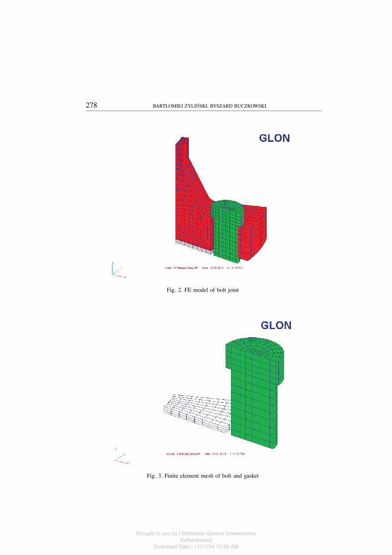
Beyond the zone where the opening takes place, the values of the contactpressure increase together with the distance along the gasket radius. Thegreatest values appear in the nodes located in the external part of the gasket.Differences in the contact pressure values appear also along the radius onboth gasket edges (Figs. 6 and 7). It can be presumed that the differences willincrease as the working load is applied. It was assumed that leakage will takeplace first at the right gasket edge. The total opening can occur even whenthe gasket is in contact with the flange on the other side. The comparisonof the contact pressure distribution along the gasket radius, computed with
Brought to you by | Biblioteka Glowna UniwersytetuAuthenticated
Download Date | 11/17/14 10:36 AM

ANALYSIS OF BOLT JOINT USING THE FINITE ELEMENT METHOD 281
Fig. 5. Distribution of contact pressure [MPa] on gasket, initial clamp F = 15 kN
the use of C3D21 and C3D28 elements, respectively, is presented in Fig. 7– the diagram refers to the right gasket edge.
Fig. 6. Contact pressure distribution along gasket radius edge on both edges
2.3.2. Computational results (phase two – working load)
As the workig load was increased, one could observe separation of theflange from the gasket and the decrease in the contact pressure on the gasket.It could be seen that the contact pressure at one of the edges of the gasket was
Brought to you by | Biblioteka Glowna UniwersytetuAuthenticated
Download Date | 11/17/14 10:36 AM
282 BARTŁOMIEJ ŻYLIŃSKI, RYSZARD BUCZKOWSKI
24 26 28 30 32 34 36 38 40 42 44 46 48 50 52 54
radius mm
0
25
50
75
co
nta
ctp
res
su
reon
the
ga
ske
tM
Pa
Element:
C3D21
C3D28
Fig. 7. Contact pressure distribution along gasket radius (the right gasket edge)
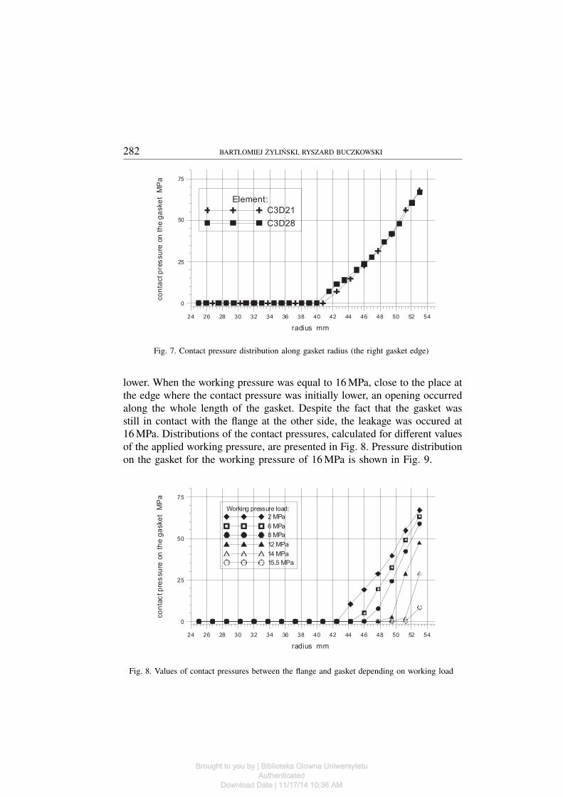
lower. When the working pressure was equal to 16 MPa, close to the place atthe edge where the contact pressure was initially lower, an opening occurredalong the whole length of the gasket. Despite the fact that the gasket wasstill in contact with the flange at the other side, the leakage was occured at16MPa. Distributions of the contact pressures, calculated for different valuesof the applied working pressure, are presented in Fig. 8. Pressure distributionon the gasket for the working pressure of 16 MPa is shown in Fig. 9.
24 26 28 30 32 34 36 38 40 42 44 46 48 50 52 54
radius mm
0
25
50
75
co
nta
ctp
res
su
reon
the
ga
ske
tM
Pa
Working pressure load:
2 MPa
6 MPa
8 MPa
12 MPa
14 MPa
15.5 MPa
Fig. 8. Values of contact pressures between the flange and gasket depending on working load
Brought to you by | Biblioteka Glowna UniwersytetuAuthenticated
Download Date | 11/17/14 10:36 AM

ANALYSIS OF BOLT JOINT USING THE FINITE ELEMENT METHOD 283
Fig. 9. Contact pressure distribution for working load of 16MPa
2.3.3. Comparison of computational results with experimental data
The dependence between the bolt force and the applied working load ispresented in Fig. 10.
0 2 4 6 8 10 12 14 16 18 20
working load MPa
12000
13000
14000
15000
16000
17000
18000
19000
bo
lta
xia
lfo
rce
N
Fig. 10. Bolt force depending on working load
Brought to you by | Biblioteka Glowna UniwersytetuAuthenticated
Download Date | 11/17/14 10:36 AM

284 BARTŁOMIEJ ŻYLIŃSKI, RYSZARD BUCZKOWSKI
In the result of the computations it was found that the leakage in thejoint occurred for the value of the working pressure of p = 16MPa. Theobtained computational results were compared to the experimental results[12]. A good agreement between both results was found. The leakage in theexperiment was detected at the working pressure p = 16.5MPa (Fig. 11).
Fig. 11. Bolt force (F f + Ft) vs. working pressure p – experimental results [12]; F f = 15 kN
denotes the initial force, Ft is an increment in axial bolt force due to working pressure p
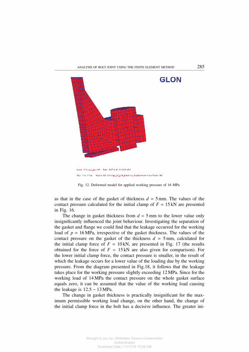
The deformed model of the joint for the working pressure of 16 MPa ispresented in Figs. 12 and 13.
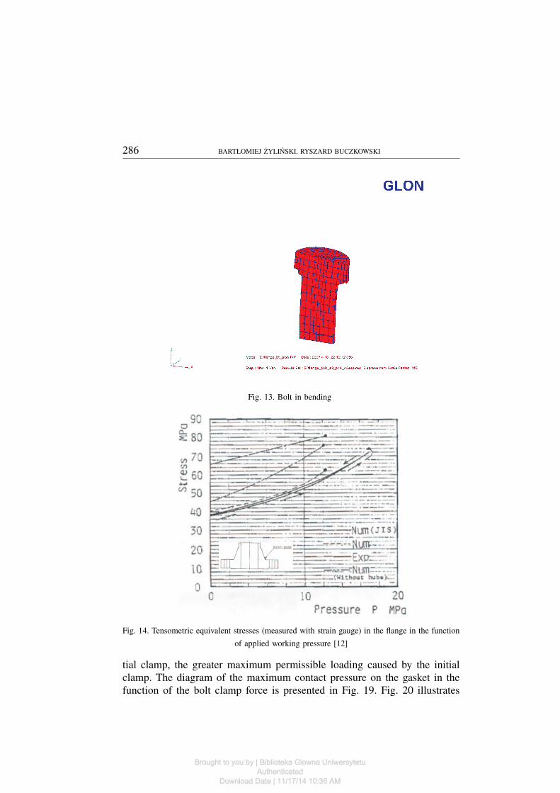
In Fig. 12, owing to the applied rescaling (scale coefficient 100), one cansee complete separation of the flange and the gasket (leakage). In Fig. 13,the deformed bolt is presented. It is clearly seen that bending of all elementsof the joint takes place here.
Stresses in the flange were also measured in the experiment [12]. Theplace of tensometric measurements and the measured stresses in the functionof the applied working load are presented in Fig. 14.
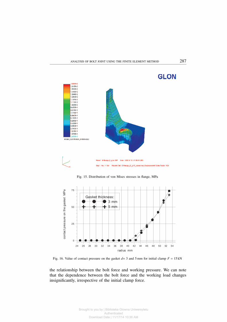
Distributions of von Mises stresses in the flange in the case of work-ing load of 16 MPa (deformed model, scale 100) are presented in Fig. 15.The greatest calculated stresses occur at the contact between the bolt headand the flange, close to the opening edge. In the place where the stresseswere measured (Fig. 14), the calculated stress value (69 − 70 MPa) and themeasured one (70 MPa), were similar.
2.3.4. Study on initial clamp and gasket thickness
In the case of the gasket of thickness d = 3mm, the distribution ofthe contact pressure between the gasket and the flange is almost identical
Brought to you by | Biblioteka Glowna UniwersytetuAuthenticated
Download Date | 11/17/14 10:36 AM
ANALYSIS OF BOLT JOINT USING THE FINITE ELEMENT METHOD 285
Fig. 12. Deformed model for applied working pressure of 16 MPa
as that in the case of the gasket of thickness d = 5mm. The values of thecontact pressure calculated for the initial clamp of F = 15 kN are presentedin Fig. 16.
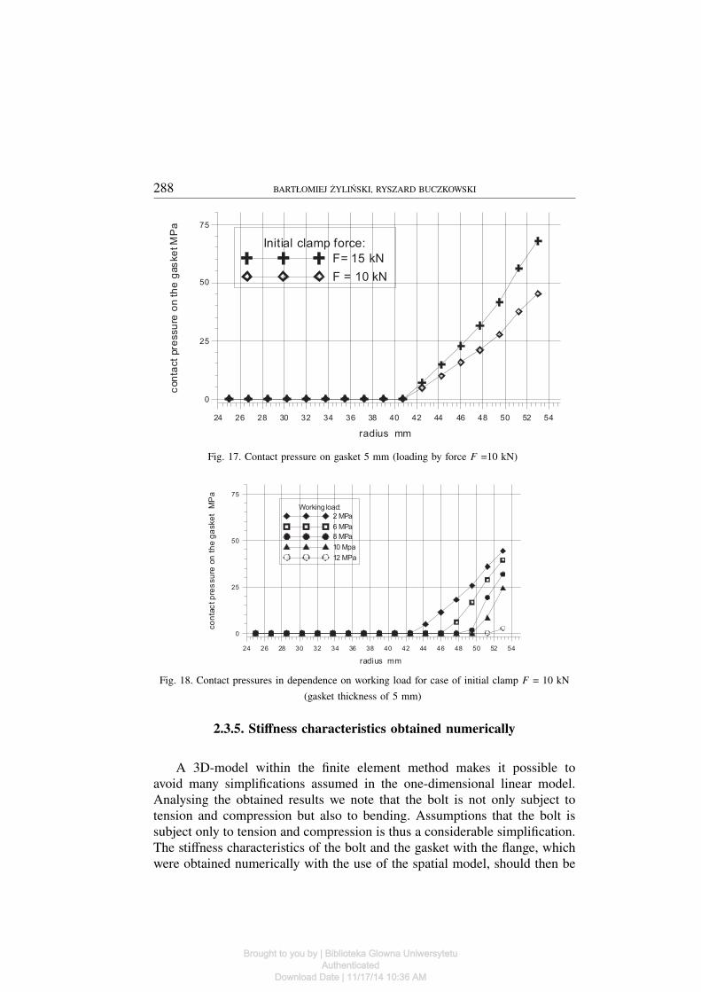
The change in gasket thickness from d = 5mm to the lower value onlyinsignificantly influenced the joint behaviour. Investigating the separation ofthe gasket and flange we could find that the leakage occurred for the workingload of p = 16MPa, irrespective of the gasket thickness. The values of thecontact pressure on the gasket of the thickness d = 5mm, calculated forthe initial clamp force of F = 10 kN, are presented in Fig. 17 (the resultsobtained for the force of F = 15 kN are also given for comparison). Forthe lower initial clamp force, the contact pressure is smaller, in the result ofwhich the leakage occurs for a lower value of the loading due by the workingpressure. From the diagram presented in Fig.18, it follows that the leakagetakes place for the working pressure slightly exceeding 12 MPa. Since for theworking load of 14 MPa the contact pressure on the whole gasket surfaceequals zero, it can be assumed that the value of the working load causingthe leakage is 12.5 − 13MPa.
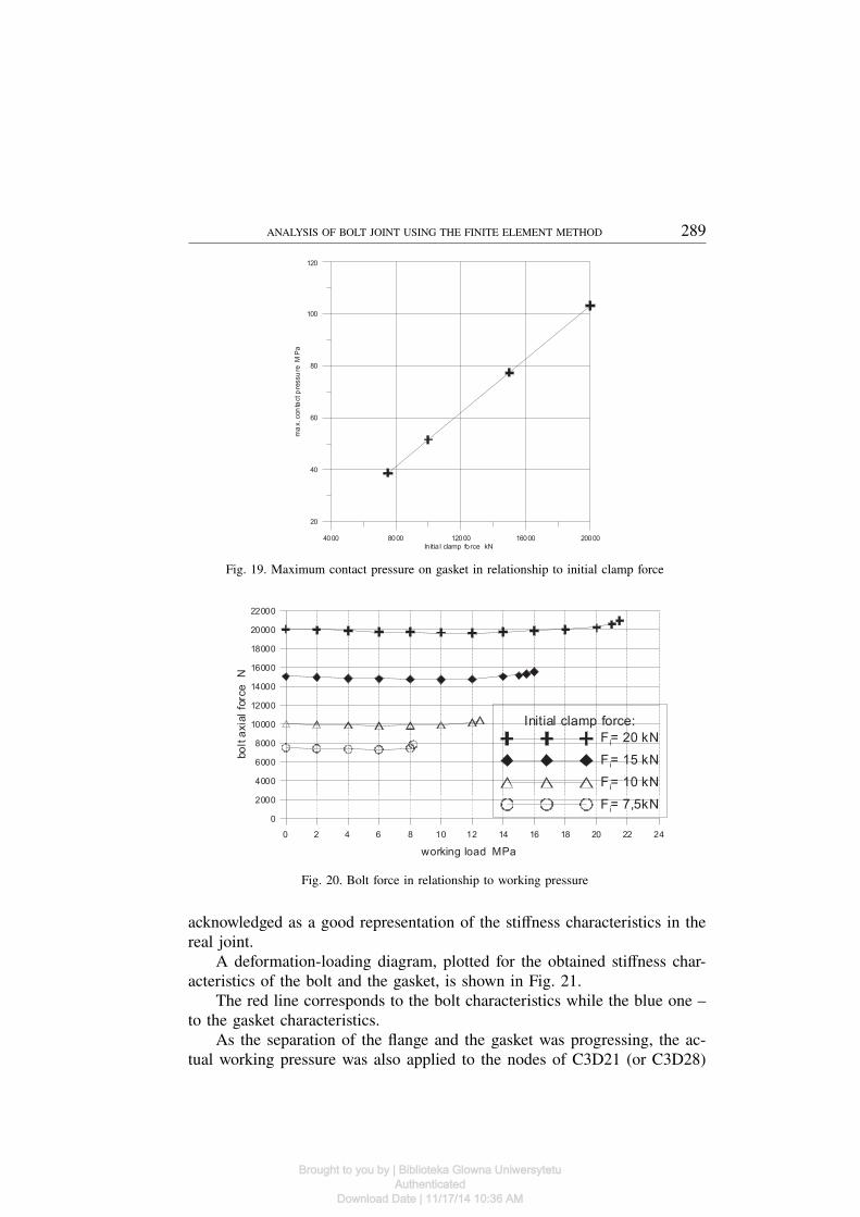
The change in gasket thickness is practically insignificant for the max-imum permissible working load change, on the other hand, the change ofthe initial clamp force in the bolt has a decisive influence. The greater ini-
Brought to you by | Biblioteka Glowna UniwersytetuAuthenticated
Download Date | 11/17/14 10:36 AM
286 BARTŁOMIEJ ŻYLIŃSKI, RYSZARD BUCZKOWSKI
Fig. 13. Bolt in bending
Fig. 14. Tensometric equivalent stresses (measured with strain gauge) in the flange in the function
of applied working pressure [12]
tial clamp, the greater maximum permissible loading caused by the initialclamp. The diagram of the maximum contact pressure on the gasket in thefunction of the bolt clamp force is presented in Fig. 19. Fig. 20 illustrates
Brought to you by | Biblioteka Glowna UniwersytetuAuthenticated
Download Date | 11/17/14 10:36 AM
ANALYSIS OF BOLT JOINT USING THE FINITE ELEMENT METHOD 287
Fig. 15. Distribution of von Mises stresses in flange, MPa
24 26 28 30 32 34 36 38 40 42 44 46 48 50 52 54
radius mm
0
25
50
75
co
nta
ctp
res
su
reon
the
ga
ske
tM
Pa
Gasket thickness:
3 mm
5 mm
Fig. 16. Value of contact pressure on the gasket d= 3 and 5 mm for initial clamp F = 15 kN
the relationship between the bolt force and working pressure. We can notethat the dependence between the bolt force and the working load changesinsignificantly, irrespective of the initial clamp force.
Brought to you by | Biblioteka Glowna UniwersytetuAuthenticated
Download Date | 11/17/14 10:36 AM
288 BARTŁOMIEJ ŻYLIŃSKI, RYSZARD BUCZKOWSKI
24 26 28 30 32 34 36 38 40 42 44 46 48 50 52 54
radius mm
0
25
50
75
con
tact
pre
ssu
reo
nth
eg
as
ke
tM
Pa
Initial clamp force:
F= 15 kN
F = 10 kN
Fig. 17. Contact pressure on gasket 5 mm (loading by force F =10 kN)
24 26 28 30 32 34 36 38 40 42 44 46 48 50 52 54
radius mm
0
25
50
75
co
nta
ctp
res
su
reon
the
ga
ske
tM
Pa
Workingload:
2 MPa
6 MPa
8 MPa
10 Mpa
12 MPa
Fig. 18. Contact pressures in dependence on working load for case of initial clamp F = 10 kN
(gasket thickness of 5 mm)
2.3.5. Stiffness characteristics obtained numerically
A 3D-model within the finite element method makes it possible toavoid many simplifications assumed in the one-dimensional linear model.Analysing the obtained results we note that the bolt is not only subject totension and compression but also to bending. Assumptions that the bolt issubject only to tension and compression is thus a considerable simplification.The stiffness characteristics of the bolt and the gasket with the flange, whichwere obtained numerically with the use of the spatial model, should then be
Brought to you by | Biblioteka Glowna UniwersytetuAuthenticated
Download Date | 11/17/14 10:36 AM
ANALYSIS OF BOLT JOINT USING THE FINITE ELEMENT METHOD 289
4000 8000 12000 16000 20000
In itia l clamp force kN
20
40
60
80
100
120
ma
x.con
tactp
ressu
reM
Pa
Fig. 19. Maximum contact pressure on gasket in relationship to initial clamp force
0 2 4 6 8 10 12 14 16 18 20 22 24
working load MPa
0
2000
4000
6000
8000
10000
12000
14000
16000
18000
20000
22000
bo
lta
xia
lfo
rce
N
Initial clamp force:
F i= 20 kN
F i= 15 kN
F i= 10 kN
F i= 7,5kN
Fig. 20. Bolt force in relationship to working pressure
acknowledged as a good representation of the stiffness characteristics in thereal joint.
A deformation-loading diagram, plotted for the obtained stiffness char-acteristics of the bolt and the gasket, is shown in Fig. 21.
The red line corresponds to the bolt characteristics while the blue one –to the gasket characteristics.
As the separation of the flange and the gasket was progressing, the ac-tual working pressure was also applied to the nodes of C3D21 (or C3D28)
Brought to you by | Biblioteka Glowna UniwersytetuAuthenticated
Download Date | 11/17/14 10:36 AM

290 BARTŁOMIEJ ŻYLIŃSKI, RYSZARD BUCZKOWSKI
elements belonging to the part of the contact surfaces of the flange bottomonly (not the gasket) that were in the separation stage.
Here, the relationships corresponding to the initial clamp from the be-ginning of the joint loading are nonlinear. It should be noted that the loadingdue to the working pressure in the gap between the gasket and the flangearising in the effect of progressing separation was additionally considered inthe FE model, what had not been taken into account in many recent papers.The green line represents the elongation-loading stiffness characteristics thattake into account the influence of the pressure.
The line is considerably divergent from the blue line representing thestiffness characteristics obtained for the case when the influence of the work-ing pressure arising as an effect of progressing opening between the flangeand the gasket was neglected.
0 0.001 0.002 0.003 0.004 0.005deformation mm
0
4
8
12
16
loa
dkN
Bolt
Flange - gasket (with pressure)
Flange - gasket (no pressure)
Fig. 21. Deformation-loading diagram for FE 3D-model with (the green characteristic) and
without influence of working pressure (the blue characteristic) between the flange and the gasket
3. Concluding remarks
Computational results for the initially-clamped bolted joint loaded byworking pressure are presented in the paper. The ABAQUS 6.8 finite element
Brought to you by | Biblioteka Glowna UniwersytetuAuthenticated
Download Date | 11/17/14 10:36 AM

ANALYSIS OF BOLT JOINT USING THE FINITE ELEMENT METHOD 291
solver was employed, in which the authors applied both the user’s elements,and the developed pre/post-processor software.
Special, spatial 21- and 28-node contact elements were applied to modelthe contact zone combined with 20-node hexahedral elements for modellingthe structure beyond the contact zone. Stiffness characteristics of the jointwere developed, considering the influence of the working pressure acting onthe bottom surface of the flange while opening between the flange and thegasket was progressing, so that the behaviour of the computational modelbetter represented the real behaviour. A very good agreement between theobtained numerical results and the measurement data given by the otherauthors was found.
Manuscript received by Editorial Board, May 06, 2010;final version, July 23, 2010.
REFERENCES
[1] Wiegand H., Kloos K.-H., Thomala W.: Schraubenverbindungen, 5.Auflage, Springer, 2007.[2] Collins J.A.: Mechanical Design of Machine Elements and Machines, Wiley, 2003.[3] Krukowski A., Tutaj J.: Połączenia odkształceniowe, PWN, Warszawa, 1987.[4] Osgood C.C.: Fatigue Design, Wiley, 1970.[5] Shigley J.E., Mischke C.R.: Mechanical Engineering Design, 5th ed., McGraw-Hill, 1988.[6] Motosh I.N.: Determination of joint stiffness in bolted connections, J. of Engineering for
Industry, Trans. of the ASME, 98, 858-861, 1976.[7] Junker G.: Systematic computation of highly stressed bolted joints, VDI-Richtlinie 2230,
1972 (in German).[8] Bickford J.H.: Introduction to the Design and Behavior of Bolted Joints, Marcel Dekker,
1981.[9] Zahavi E.: A finite element analysis of flange connections’, Journal of Pressure Vessel Tech-
nology, Trans. of the ASME, 115, 327-330, 1993.[10] Zahavi E.: The Finite Element Method in Machine Design, Prentice-Hall, 1992.[11] Zahavi E., Barlam D.: Nonlinear Problems in Machine Design, CRC Press, 2001.[12] Sawa T., Higurashi N., Akagawa H.: A stress analysis of pipe flange connections’, International
Journal of Pressure Vessel Technology, Trans. of the ASME, 113, 497-503, 1991.[13] Buczkowski R.: ‘21-noded hexahedral isoparametric element for analysis of contact problems’,
Communications in Numerical Methods in Engineering, 14, 681-692 (1998).[14] Buczkowski R., Gabbert U.: ‘28-noded hexahedral isoparametric element for analysis of
contact problems’, Communications in Numerical Methods in Engineering, 20, 147-161,2004.
Analiza połączenia kołnierzowego metodą elementów skończonych
S t r e s z c z e n i e
W pracy przedstawiono numeryczną analizę połączenia kołnierzowego z uszczelką obciążonegozaciskiem wstępnym i ciśnieniem roboczym. W strefie kontaktu pomiędzy uszczelką a kołnierzem
Brought to you by | Biblioteka Glowna UniwersytetuAuthenticated
Download Date | 11/17/14 10:36 AM

292 BARTŁOMIEJ ŻYLIŃSKI, RYSZARD BUCZKOWSKI
zastosowano specjalne przestrzenne 21- i 28-węzłowe izoparametryczne elementy skończone. W mo-delu obliczeniowym uwzględniono również obciążenie od ciśnienia roboczego panującego w szczeli-nie pomiędzy uszczelką a kołnierzem w wyniku postępującego otwarcia połączenia, co jest pewnąnowością w porównaniu do najnowszych prac opublikowanych z tej tematyki. Sporządzono nielini-owe charakterystyki sztywnościowe śruby i kołnierza z uszczelką. Określono wartość ciśnieniaroboczego odpowiadającego sile krytycznej w śrubie powodującego przeciek w połączeniu (całkowi-cie otwarcie pomiędzy uszczelką a kołnierzem). Wyniki obliczeniowe MES porównano z dostęp-nymi wynikami doświadczalnymi. Wyniki numeryczne zilustrowano przy pomocy własnego post-procesora graficznego.
Brought to you by | Biblioteka Glowna UniwersytetuAuthenticated
Download Date | 11/17/14 10:36 AM