Manufacturing Cosine Die Profile for Tubes Hydroforming Test (Bulging)
Information contained within is specific to Ecoply® Barrier structural plywood products and must not be used with any other plywood products, no matter how similar they may appear.
BARRIERSpecification & inStallation GuideS e p t e m b e r 2 0 1 5
Contents1.0 Ecoply® Barrier ...........................................................32.0 Ecoply Brand ..............................................................43.0 Technical Information and CAD Details ............44.0 Ecoply Barrier Advantages ......................................44.1 Architects / Designers ............................................44.2 Builders ......................................................................54.3 Homeowners ............................................................55.0 Ecoply Barrier System ..............................................65.1 Tapes ...........................................................................65.2 Coating – Panels........................................................66.0 Design Considerations ............................................77.0 Installation ..................................................................87.1 Installation ..................................................................87.2 Installation – Sealing Tape .......................................97.3 Installation – Sill Tape ............................................127.4 Installation – Frame Sealing Tape ........................137.5 Service Penetrations ...............................................147.6 Structural Bracing....................................................157.7 Ecoply Barrier Bracing Specification – EPB1 ....167.8 Ecoply Barrier Bracing Specification – EPBS ....177.9 Ecoply Barrier Bracing Specification – EPBG ...187.10 GIB Handibrac® – Recommended Installation Method....................197.11 Top Plate Hold Down Connections ...................207.12 Lintel Tie Down Connection ...............................208.0 Fire Rated Systems .................................................219.0 Cladding System Installation .................................2110.0 Working Instructions .............................................2111.0 Referenced Documents .........................................2112.0 Frequently Asked Questions ................................2213.0 Limitations ................................................................2214.0 Ecoply Barrier Installation Checklist ..................23
3CHH WoodproduCts | ECoply® BarriEr | 0800 326 759 | www.chhwoodproducts.co.nz
Eco
ply® Ba
rr
iEr
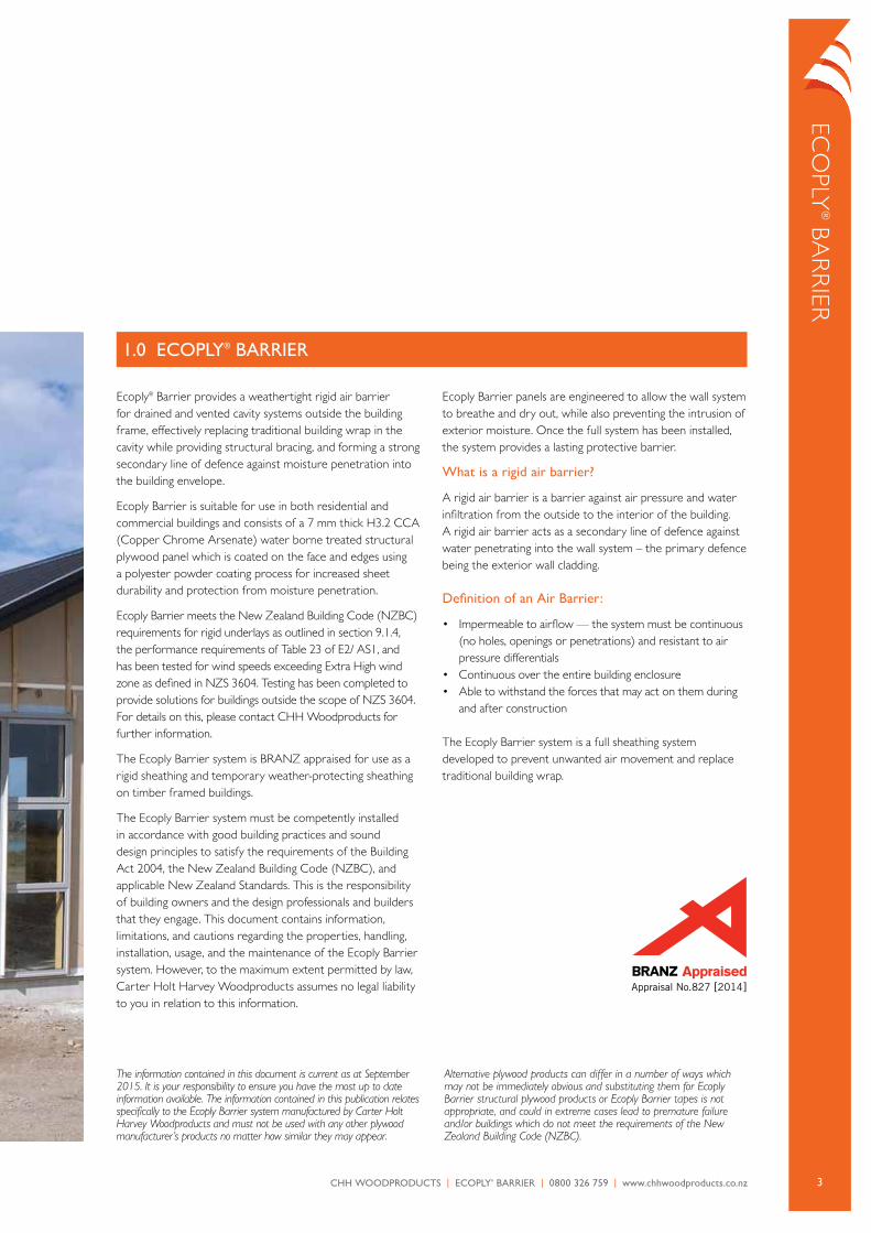
Ecoply® Barrier provides a weathertight rigid air barrier for drained and vented cavity systems outside the building frame, effectively replacing traditional building wrap in the cavity while providing structural bracing, and forming a strong secondary line of defence against moisture penetration into the building envelope.
Ecoply Barrier is suitable for use in both residential and commercial buildings and consists of a 7 mm thick H3.2 cca (copper chrome arsenate) water borne treated structural plywood panel which is coated on the face and edges using a polyester powder coating process for increased sheet durability and protection from moisture penetration.
Ecoply Barrier meets the New Zealand Building code (NZBc) requirements for rigid underlays as outlined in section 9.1.4, the performance requirements of Table 23 of E2/ aS1, and has been tested for wind speeds exceeding Extra High wind zone as defined in NZS 3604. Testing has been completed to provide solutions for buildings outside the scope of NZS 3604. For details on this, please contact cHH Woodproducts for further information.
The Ecoply Barrier system is BraNZ appraised for use as a rigid sheathing and temporary weather-protecting sheathing on timber framed buildings.
The Ecoply Barrier system must be competently installed in accordance with good building practices and sound design principles to satisfy the requirements of the Building act 2004, the New Zealand Building code (NZBc), and applicable New Zealand Standards. This is the responsibility of building owners and the design professionals and builders that they engage. This document contains information, limitations, and cautions regarding the properties, handling, installation, usage, and the maintenance of the Ecoply Barrier system. However, to the maximum extent permitted by law, carter Holt Harvey Woodproducts assumes no legal liability to you in relation to this information.
Ecoply Barrier panels are engineered to allow the wall system to breathe and dry out, while also preventing the intrusion of exterior moisture. once the full system has been installed, the system provides a lasting protective barrier.
What is a rigid air barrier?
a rigid air barrier is a barrier against air pressure and water infiltration from the outside to the interior of the building. a rigid air barrier acts as a secondary line of defence against water penetrating into the wall system – the primary defence being the exterior wall cladding.
Definition of an Air Barrier:
• impermeable to airflow — the system must be continuous (no holes, openings or penetrations) and resistant to air pressure differentials
• continuous over the entire building enclosure• able to withstand the forces that may act on them during
and after construction
The Ecoply Barrier system is a full sheathing system developed to prevent unwanted air movement and replace traditional building wrap.
1.0 ECoPLy® BARRIER
The information contained in this document is current as at September 2015. It is your responsibility to ensure you have the most up to date information available. The information contained in this publication relates specifically to the Ecoply Barrier system manufactured by Carter Holt Harvey Woodproducts and must not be used with any other plywood manufacturer’s products no matter how similar they may appear.
Alternative plywood products can differ in a number of ways which may not be immediately obvious and substituting them for Ecoply Barrier structural plywood products or Ecoply Barrier tapes is not appropriate, and could in extreme cases lead to premature failure and/or buildings which do not meet the requirements of the New Zealand Building Code (NZBC).
Appraisal No.827 [2014]

4 CHH WoodproduCts | ECoply® BarriEr | 0800 326 759 | www.chhwoodproducts.co.nz
Eco
ply
® B
ar
riE
r
4.1 ARCHITECTS / DESIGnERS
Modern construction practices are moving toward providing greater energy efficiency and an airtight building envelope. These principles of high performance building are common in nearly all current green building standards and construction codes. proper sealing between wall assembly components prevents unwanted air movement in and out of conditioned air spaces.
• Ecoply Barrier can form an integral part of a weathertight system including two of the four ‘Ds’ of weathertightness; drying and drainage
• a rigid air barrier provides a more robust cavity and prevents the insulation bulging, which would increase the chance of moisture bridging from the cladding to the framing line
• provides both structure support and protection from moisture. Structural bracing is achieved when installed in accordance with the Ecoply Barrier bracing specifications. Bracing benefits may result in cost savings by reducing internal lining bracing elements (refer to section 7.6 on bracing – pg 15)
• BraNZ appraised system, fully tested and code compliant rigid air barrier system
• Manufactured from sustainable plantation pine and available FSc certified (ScS-coc-001316) upon request
• low formaldehyde emission level (Eo)
4.0 ECoPLy® BARRIER ADVAnTAGES
Appraisal No.827 [2014]
2.0 ECoPLy® BRAnD
Ecoply Barrier panels are manufactured in New Zealand by cHH Woodproducts under a third party audited quality control programme to monitor compliance with aS/NZS 2269 – plywood Structural.
product test reports, technical data sheets and caD drawings referenced in this guide are downloadable from www.chhwoodproducts.co.nz
carter Holt Harvey Ecoply Barrier (rigid air Barrier) is compliant with NZBc clause B2.3.1 (a), for not less than 50 years, when used where the cladding durability requirement or serviceable life is not less than 50 years, e.g. structural bracing,
and compliant with NZBc clause B2.3.1 (b), for 15 years where the cladding durability requirement is 15 years when used as a temporary sheathing.
When specifying or installing the Ecoply Barrier system visit www.chhwoodproducts.co.nz or call 0800 326 759 to ensure you have current specification material and any relevant technical notes.
3.0 TECHnICAL InFoRMATIon AnD CAD DETAILS

5CHH WoodproduCts | ECoply® BarriEr | 0800 326 759 | www.chhwoodproducts.co.nz
Eco
ply® Ba
rr
iEr
4.2 BuILDERS
Ecoply Barrier lets you say goodbye to flexible wall underlays forever. Builders no longer have to worry about installing traditional housewrap or building paper on a windy day or having to return for re-work due to rips, tears or wrap that has blown off the home. The Ecoply Barrier system can typically save up to 2-4* weeks off the total house build time*, by allowing a faster building close in, for an earlier interior start and a quicker overall build time.
The Ecoply Barrier system installs quickly with two easy steps – fasten the panels and tape the seams. once completed, the system provides moisture protection both during and after construction.
• immediate close-in of structure, allowing interior and exterior work to be completed in parallel
• reduced builder liability; strong secondary line of defence and solid material for sealing penetrations
• Schedule your subcontractors sooner
• No call backs for rips, tears or wrap that has blown off• Easy to work light material, simple and easy to install• Up to 90 day exposure during construction cycle. No hold-ups
while the cladding has to be installed i.e. brick layers etc
4.3 HoMEoWnERS
an airtight building envelope means less airflow into and out of the home. Since conditioned air is expensive air, homeowners can take comfort in knowing that Ecoply Barrier will provide a strong secondary line of defence against the elements.
• Get possession faster, builders building with Ecoply Barrier can typically reduce up to 2-4* weeks off a typical house build*
• Structurally rigid home
* Timeframes and efficiencies are indicative only. construction production gains will differ with respect to individual builder’s abilities and other contributing circumstances outside the control of cHH Woodproducts.
6 CHH WoodproduCts | ECoply® BarriEr | 0800 326 759 | www.chhwoodproducts.co.nz
Eco
ply
® B
ar
riE
r S
yST
EM
5.1 TAPES
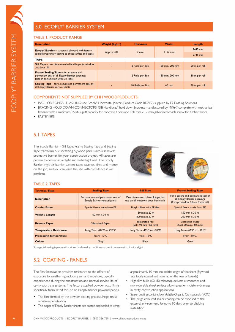
The Ecoply Barrier – Sill Tape, Frame Sealing Tape and Sealing Tape transform our sheathing plywood panels into a seamless protective barrier for your construction project. all tapes are proven to deliver an airtight and watertight seal. The Ecoply Barrier ‘rigid air barrier system’ tapes save you time and money on the job; and you can leave the site with confidence it will perform.
TABLE 2: TAPES
Technical Data Sealing Tape Sill Tape Frame Sealing Tape
Description For a secure and permanent seal of Ecoply Barrier vertical joints
one piece stretchable sill tape, for use on all window / door frame sills
For a secure and permanent seal of all Ecoply Barrier openings
(Except window / door frame sill)
Carrier Paper Special fleece made from PP Butyl rubber with PE film Special fleece made from PP
Width / Length 60 mm x 30 m150 mm x 20 m200 mm x 20 m
150 mm x 30 m200 mm x 30 m
Release Paper Siliconized Paper Siliconized Foil (Split 90 mm / 60 mm)
Siliconized Paper (Split 90 mm / 60 mm)
Temperature Resistance Long Term -40°C to +90°C Long Term -40°C to +90°C Long Term -40°C to +90°C
Processing Temperature From -10°C From -10°C From -10°C
Colour Grey Black Grey
Storage: all sealing tapes must be stored in clean dry conditions and not in an area with direct sunlight.
TABLE 1: PRoDuCT RAnGE
Description Weight (kg/m2) Thickness Width Length
Ecoply® Barrier – structural plywood with factory applied proprietary coating to sheet surface and edges Approx 4.0 7 mm 1197 mm
2440 mm
2745 mm
TAPE
Sill Tape – one piece stretchable sill tape for window and door sills - 2 Rolls per Box 150 mm, 200 mm 20 m per roll
Frame Sealing Tape – for a secure and permanent seal of all Ecoply Barrier openings (use in conjunction with Sill Tape)
- 2 Rolls per Box 150 mm, 200 mm 30 m per roll
Sealing Tape – for a secure and permanent seal of all Ecoply Barrier vertical joints - 10 Rolls per Box 60 mm 30 m per roll
CoMPonEnTS noT SuPPLIED By CHH WooDPRoDuCTS:• pVc HoriZoNTal FlaSHiNG: use Ecoply® Horizontal Jointer (product code rDZF7) supplied by E2 Flashing Solutions• BraciNG HolD DoWN coNNEcTorS: GiB Handibrac® hold down brackets manufactured by MiTek® complete with mechanical
fastener with a minimum 15 kN uplift capacity for concrete floors and 150 mm x 12 mm galvanised coach screw for timber floors• FaSTENErS
5.0 ECoPLy® BARRIER SySTEM
5.2 CoATInG - PAnELS
The film formulation provides resistance to the effects of exposure to weathering including sun and moisture, typically experienced during the construction and normal service life of cavity substrate systems. The factory applied powder coat film is specifically formulated for use on Ecoply Barrier plywood panels.
• The film, formed by the powder coating process, helps resist moisture penetration
• The edges of Ecoply Barrier sheets are coated and sealed to wrap
approximately 10 mm around the edges of the sheet (plywood face totally coated, with overlap on the rear of boards)
• High film build (60–80 microns), delivers a smoother and more durable sheet surface allowing easier moisture drainage in cavity construction applications
• Sealer coating contains low Volatile organic compounds (Voc)• The beige coloured sealer coating can be exposed to the
external environment for up to 90 days prior to cladding installation

7CHH WoodproduCts | ECoply® BarriEr | 0800 326 759 | www.chhwoodproducts.co.nz
Responsibility
Design responsibility lies with the building owner and the professionals that they engage. The Specifier for the project must ensure that the products and details in the specification are appropriate for the intended application and that additional detailing is provided for specific design or any areas that fall outside the scope and specifications of this literature.
Preservative Treatment
Ecoply® Barrier is treated in accordance with aS/NZS 1604.3 with H3.2 cca (copper chrome arsenate) water borne treatment. H3.2 cca treated plywood in accordance with aS/NZS 1604.3 is described as suitable for: “outside above ground applications” and periodic moderate wetting.
Cut Sheets
Ecoply Barrier is envelope preservative treated. if a sheet end is cut, place the cut end to the top. always have a sealed sheet end at the bottom to minimise potential moisture ingress into the panel. all other cuts and penetrations must be covered by a suitable flexible sealing tape and installed in accordance with the Ecoply Barrier literature. When installed as per the above requirements, cut edges and penetrations are not required to be retreated with a brush on preservative treatment however if desired cHH Woodproducts recommends the use of Holdfast® Metalex® concentrated Timber preservative clear (Holdfast® Metalex® clear).
Dimensional Sheet Change
Detailing and construction using Ecoply Barrier must allow for natural movement in line with normal cycles of moisture change occurring in the environment. The total expansion both along and across a 2440 x 1197 mm panel can be in the order of 1.5 mm to 3 mm depending on the environment. Detailing and construction practice should take the potential for natural movement into consideration. Ecoply Barrier sheets may exhibit slight sheet bowing across the sheet resulting from the preservative treatment and surface coating processes. This is to be expected and will not affect the products structural performance or weathertightness when installed as per specifications.
Formaldehyde
Formaldehyde occurs naturally in the environment and is emitted by processes such as combustion, decay and naturally by all timber species. Ecoply Barrier meets the lowest formaldehyde emission classification (Eo – less than 0.5 mg/ litre).
Wind Loadings
Ecoply Barrier meets the NZBc requirements for rigid underlays as outlined in section 9.1.4, the performance requirements of Table 23 of E2/ aS1, and has been tested for wind speed exceeding Extra High wind zone as defined in NZS 3604. Testing has been completed to provide solutions for buildings outside the scope of NZS 3604. contact cHH Woodproducts for further information.
Sustainability
Ecoply Barrier is manufactured from radiata pine, a plantation grown medium density softwood. it is grown on tree farms which are tended and harvested to provide wood for plywood manufacture. The crop is managed on a sustainable basis to yield millable trees. Ecoply Barrier is available Forestry Stewardship council (ScS-coc-001316) certified upon request.
Health & Safety
Ecoply Barrier should be handled in accordance with the Material Safety Data Sheet (MSDS) for H3.2 cca treated Ecoply. always wear safety glasses or non fogging goggles when working with Ecoply Barrier. if wood dust exposure is not controlled when machining (sawing, drilling etc) a p1 or p2 replaceable filter or disposable face piece respirator should be worn. Wear comfortable work gloves to avoid skin irritation and the risk of splinters. Wash hands with mild soap and water after handling panels.
Storage & Handling
Ecoply Barrier panels and tapes must be stored and handled with care to maintain good condition prior to installation:
• The storage area must be protected from sun, rain and wind that would otherwise bring about rapid changes in temperature and humidity
• Support for the sheets must be provided at both ends and middle to avoid distortion. Ensure bearers in packs above are aligned over bearers below to avoid inducing curves in sheets
• The stack must be kept dry and clear of ground contact, and placed so that it will not be exposed to mechanical damage
• The sheets must be stacked flat, NoT on edge
Maintenance
Ecoply Barrier will not normally require maintenance. However, if damage occurs to the cladding or lining protecting the Ecoply Barrier or to the Ecoply Barrier itself, repairs or replacement should be carried out to ensure the integrity of the rigid air barrier. Small perforations in the panels can be covered by the Frame Sealing Tape or Sealing Tape (200 mm, 150 mm or 60 mm Width, Grey colour)
Eco
ply® Ba
rr
iEr D
ESiGN
co
NSiD
Era
Tio
NS
6.0 DESIGn ConSIDERATIonS
8 CHH WoodproduCts | ECoply® BarriEr | 0800 326 759 | www.chhwoodproducts.co.nz
Eco
ply
® B
ar
riE
r iN
STa
lla
Tio
N
7.0 InSTALLATIon
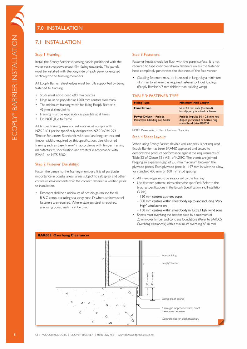
Concrete slab or block masonary
Damp proof course
Ecoply® Barrier
Interior lining
25 m
m m
in
6 mm gap or provide water proof membrane between
scale 1:2ECOPLY. BAR005 Overhang clearances
100500
40 m
m m
ax
BAR005: Overhang Clearances
7.1 InSTALLATIon
Step 1 Framing:
install the Ecoply Barrier sheathing panels positioned with the water-resistive powdercoat film facing outwards. The panels must be installed with the long side of each panel orientated vertically to the framing members.
all Ecoply Barrier sheet edges must be fully supported by being fastened to framing:
• Studs must not exceed 600 mm centres• Nogs must be provided at 1200 mm centres maximum• The minimum framing width for fixing Ecoply Barrier is
45 mm at sheet joints• Framing must be kept as dry as possible at all times• Do NoT glue to frame
all timber framing sizes and set outs must comply with NZS 3604 (or be specifically designed to NZS 3603:1993 – Timber Structures Standard), with stud and nog centres and timber widths required by this specification. Use kiln dried framing such as laserframe® in accordance with timber framing manufacturers specification and treated in accordance with B2/aS1 or NZS 3602.
Step 2 Fastener Durability:
Fasten the panels to the framing members. it is of particular importance in coastal areas, areas subject to salt spray and other corrosive environments that the correct fastener is verified prior to installation.
• Fasteners shall be a minimum of hot dip galvanised for all B & c zones excluding sea spray zone D where stainless steel fasteners are required. Where stainless steel is required, annular grooved nails must be used
Step 3 Fasteners:
Fastener heads should be flush with the panel surface. it is not required to tape over overdriven fasteners unless the fastener head completely penetrates the thickness of the face veneer.
• cladding fasteners must be increased in length by a minimum of 7 mm to achieve the required fastener pull out loadings. (Ecoply Barrier is 7 mm thicker than building wrap)
TABLE 3: FASTEnER TyPE
Fixing Type Minimum Nail Length
Hand Driven 50 x 2.8 mm nails (flat head), hot dipped galvanised or better
Power Driven – Paslode Pneumatic Cladding coil nailer
Paslode Impulse 50 x 2.8 mm hot dipped galvanised or better, ring round head drive B20557
NoTE: please refer to Step 2 Fastener Durability.
Step 4 Sheet Layout:
When using Ecoply Barrier, flexible wall underlay is not required. Ecoply Barrier has been BraNZ appraised and tested to demonstrate product performance against the requirements of Table 23 of clause E2 / aS1 of NZBc. The sheets are jointed keeping an expansion gap of 2-3 mm maximum between the plywood panels. Each plywood panel is 1197 mm in width to allow for standard 400 mm or 600 mm stud spacing.
• all sheet edges must be supported by the framing• Use fastener pattern unless otherwise specified (refer to the
bracing specifications in the Ecoply Specification and installation Guide) - 150 mm centres at sheet edges - 300 mm centres within sheet body up to and including ‘Very High’ wind zone or;
- 150 mm centres within sheet body in ‘extra High’ wind zone• Sheets must overhang the bottom plate by a minimum of
25 mm over timber and concrete foundations (refer to Bar005: overhang clearances.) with a maximum overhang of 40 mm
9CHH WoodproduCts | ECoply® BarriEr | 0800 326 759 | www.chhwoodproducts.co.nz
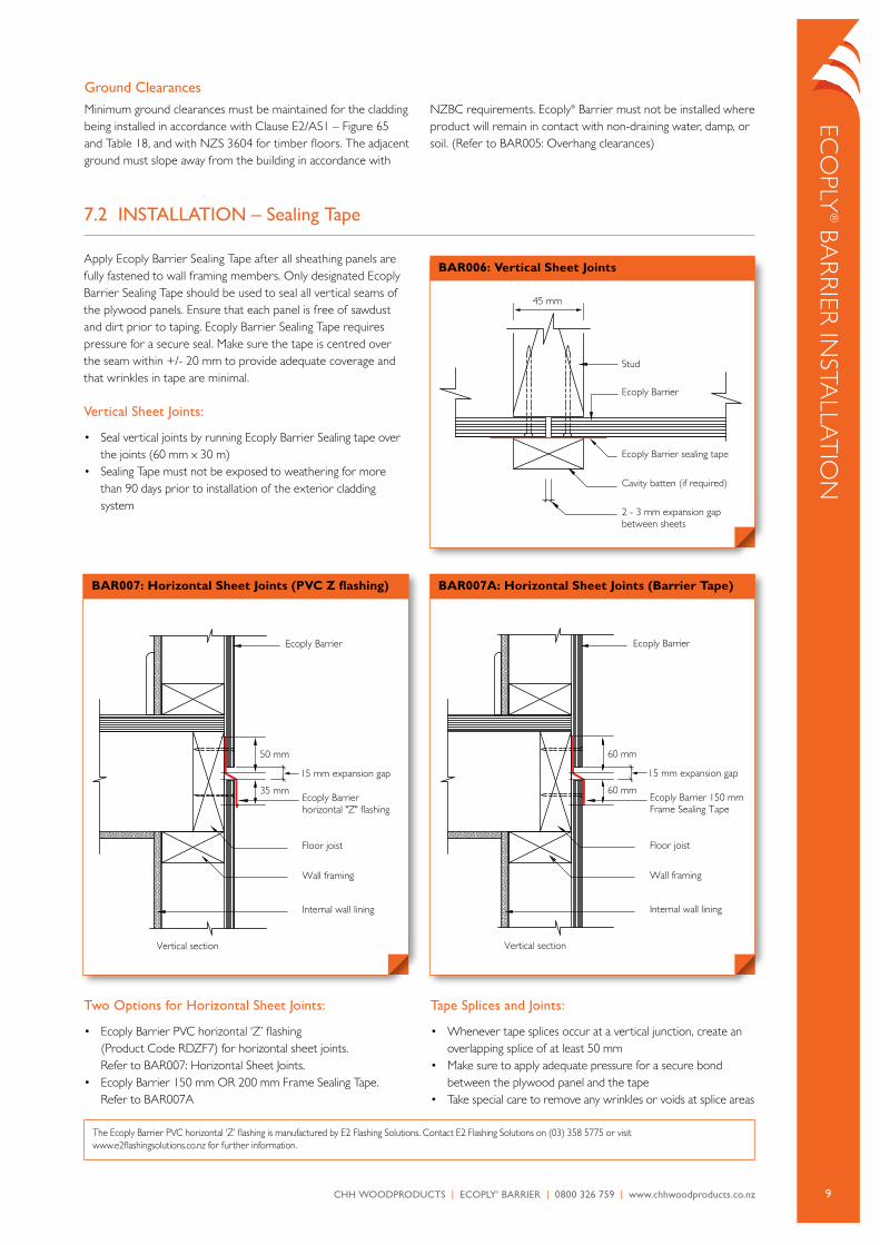
Ecoply Barrier
15 mm expansion gap
Ecoply Barrier horizontal "Z" flashing
Internal wall lining
Vertical section
Floor joist
Wall framing
scale 1:5ECOPLY. BAR007 Horizontal Sheet Joint
200100500
50 mm
35 mm
BAR007: Horizontal Sheet Joints (PVC Z flashing)
Ecoply Barrier
15 mm expansion gap
Ecoply Barrier horizontal "Z" flashing
Internal wall lining
Vertical section
Floor joist
Wall framing
scale 1:5ECOPLY. BAR007 Horizontal Sheet Joint
200100500
50 mm
35 mm
BAR007A: Horizontal Sheet Joints (Barrier Tape)
Eco
ply® Ba
rr
iEr iN
STalla
Tio
N
7.2 InSTALLATIon – Sealing Tape
apply Ecoply Barrier Sealing Tape after all sheathing panels are fully fastened to wall framing members. only designated Ecoply Barrier Sealing Tape should be used to seal all vertical seams of the plywood panels. Ensure that each panel is free of sawdust and dirt prior to taping. Ecoply Barrier Sealing Tape requires pressure for a secure seal. Make sure the tape is centred over the seam within +/- 20 mm to provide adequate coverage and that wrinkles in tape are minimal.
Vertical Sheet Joints:
• Seal vertical joints by running Ecoply Barrier Sealing tape over the joints (60 mm x 30 m)
• Sealing Tape must not be exposed to weathering for more than 90 days prior to installation of the exterior cladding system
Two options for Horizontal Sheet Joints:
• Ecoply Barrier pVc horizontal ‘Z’ flashing (product code rDZF7) for horizontal sheet joints. refer to Bar007: Horizontal Sheet Joints.
• Ecoply Barrier 150 mm or 200 mm Frame Sealing Tape. refer to Bar007a
Tape Splices and Joints:
• Whenever tape splices occur at a vertical junction, create an overlapping splice of at least 50 mm
• Make sure to apply adequate pressure for a secure bond between the plywood panel and the tape
• Take special care to remove any wrinkles or voids at splice areas
Ground ClearancesMinimum ground clearances must be maintained for the cladding being installed in accordance with clause E2/aS1 – Figure 65 and Table 18, and with NZS 3604 for timber floors. The adjacent ground must slope away from the building in accordance with
NZBc requirements. Ecoply® Barrier must not be installed where product will remain in contact with non-draining water, damp, or soil. (refer to Bar005: overhang clearances)
45 mm
Stud
Ecoply Barrier sealing tape
Ecoply Barrier
Cavity batten (if required)
2 - 3 mm expansion gap between sheets
scale 1:2ECOPLY. BAR006 Vertical sheet joints
100500
BAR006: Vertical Sheet Joints
The Ecoply Barrier pVc horizontal ‘Z’ flashing is manufactured by E2 Flashing Solutions. contact E2 Flashing Solutions on (03) 358 5775 or visit www.e2flashingsolutions.co.nz for further information.
Ecoply Barrier
15 mm expansion gap
Ecoply Barrier 150 mmFrame Sealing Tape
Internal wall lining
Vertical section
Floor joist
Wall framing
scale 1:5ECOPLY. BAR007 Horizontal Sheet Joint
200100500
60 mm
60 mm
10 CHH WoodproduCts | ECoply® BarriEr | 0800 326 759 | www.chhwoodproducts.co.nz
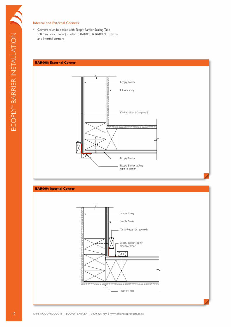
Internal and External Corners:
• corners must be sealed with Ecoply Barrier Sealing Tape (60 mm Grey colour). (refer to Bar008 & Bar009: External and internal corner)
Eco
ply
® B
ar
riE
r iN
STa
lla
Tio
N
Ecoply Barrier
Interior lining
Cavity batten (if required)
Ecoply Barrier
Ecoply Barrier sealing tape to corner
scale 1:5ECOPLY. BAR008 External Corner
200100500
BAR008: External Corner
Interior lining
Ecoply Barrier
Cavity batten (if required)
Ecoply Barrier sealing tape to corner
Interior lining
scale 1:5ECOPLY. BAR009 Internal Corner
200100500
BAR009: Internal Corner
11CHH WoodproduCts | ECoply® BarriEr | 0800 326 759 | www.chhwoodproducts.co.nz
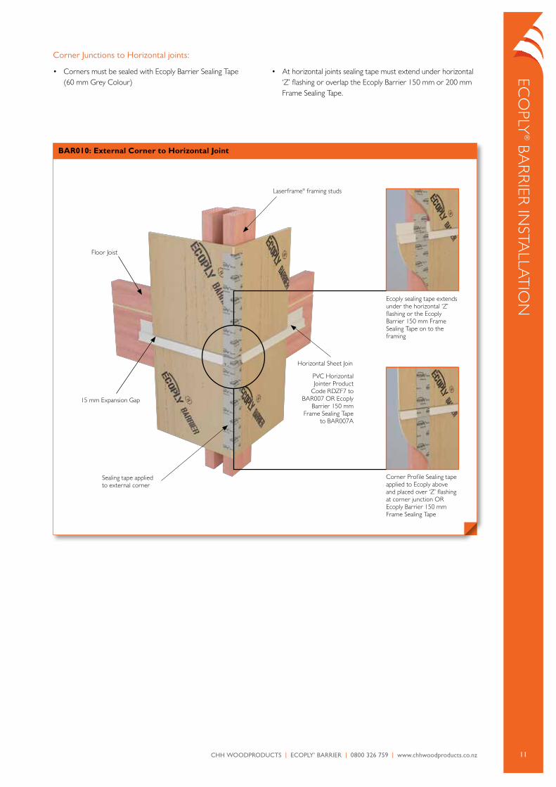
corner Junctions to Horizontal joints:
• corners must be sealed with Ecoply Barrier Sealing Tape (60 mm Grey colour)
• at horizontal joints sealing tape must extend under horizontal ‘Z’ flashing or overlap the Ecoply Barrier 150 mm or 200 mm Frame Sealing Tape.
Eco
ply® Ba
rr
iEr iN
STalla
Tio
N
BAR010: External Corner to Horizontal Joint
laserframe® framing studs
Horizontal Sheet Join
pVc Horizontal Jointer product
code rDZF7 to Bar007 or Ecoply
Barrier 150 mm Frame Sealing Tape
to Bar007a
Sealing tape applied to external corner
15 mm Expansion Gap
Floor Joist
corner profile Sealing tape applied to Ecoply above and placed over ‘Z’ flashing at corner junction or Ecoply Barrier 150 mm Frame Sealing Tape
Ecoply sealing tape extends under the horizontal ‘Z’ flashing or the Ecoply Barrier 150 mm Frame Sealing Tape on to the framing
12 CHH WoodproduCts | ECoply® BarriEr | 0800 326 759 | www.chhwoodproducts.co.nz
Eco
ply
® B
ar
riE
r iN
STa
lla
Tio
N
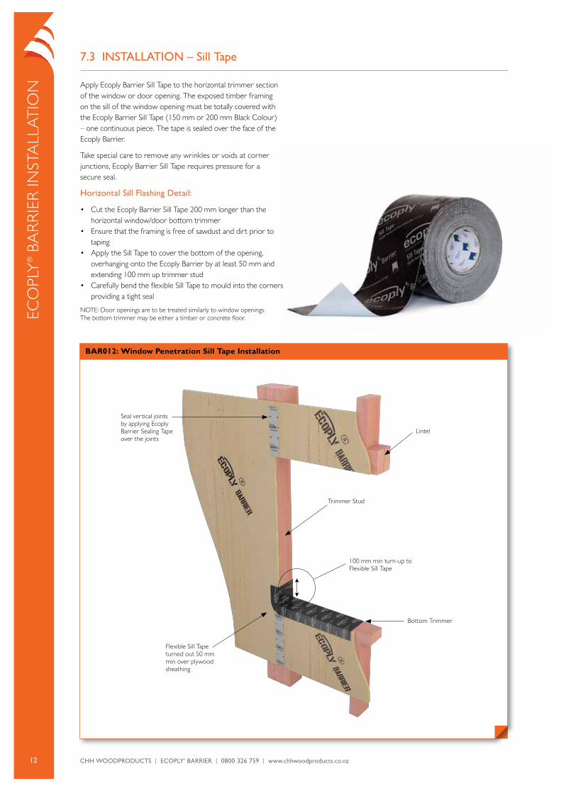
7.3 InSTALLATIon – Sill Tape
apply Ecoply Barrier Sill Tape to the horizontal trimmer section of the window or door opening. The exposed timber framing on the sill of the window opening must be totally covered with the Ecoply Barrier Sill Tape (150 mm or 200 mm Black colour) – one continuous piece. The tape is sealed over the face of the Ecoply Barrier.
Take special care to remove any wrinkles or voids at corner junctions, Ecoply Barrier Sill Tape requires pressure for a secure seal.
Horizontal Sill Flashing Detail:
• cut the Ecoply Barrier Sill Tape 200 mm longer than the horizontal window/door bottom trimmer
• Ensure that the framing is free of sawdust and dirt prior to taping
• apply the Sill Tape to cover the bottom of the opening, overhanging onto the Ecoply Barrier by at least 50 mm and extending 100 mm up trimmer stud
• carefully bend the flexible Sill Tape to mould into the corners providing a tight seal
NoTE: Door openings are to be treated similarly to window openings. The bottom trimmer may be either a timber or concrete floor.
BAR012: Window Penetration Sill Tape Installation
Seal vertical joints by applying Ecoply Barrier Sealing Tape over the joints
lintel
Trimmer Stud
Bottom Trimmer
100 mm min turn-up to Flexible Sill Tape
Flexible Sill Tape turned out 50 mm min over plywood sheathing
13CHH WoodproduCts | ECoply® BarriEr | 0800 326 759 | www.chhwoodproducts.co.nz
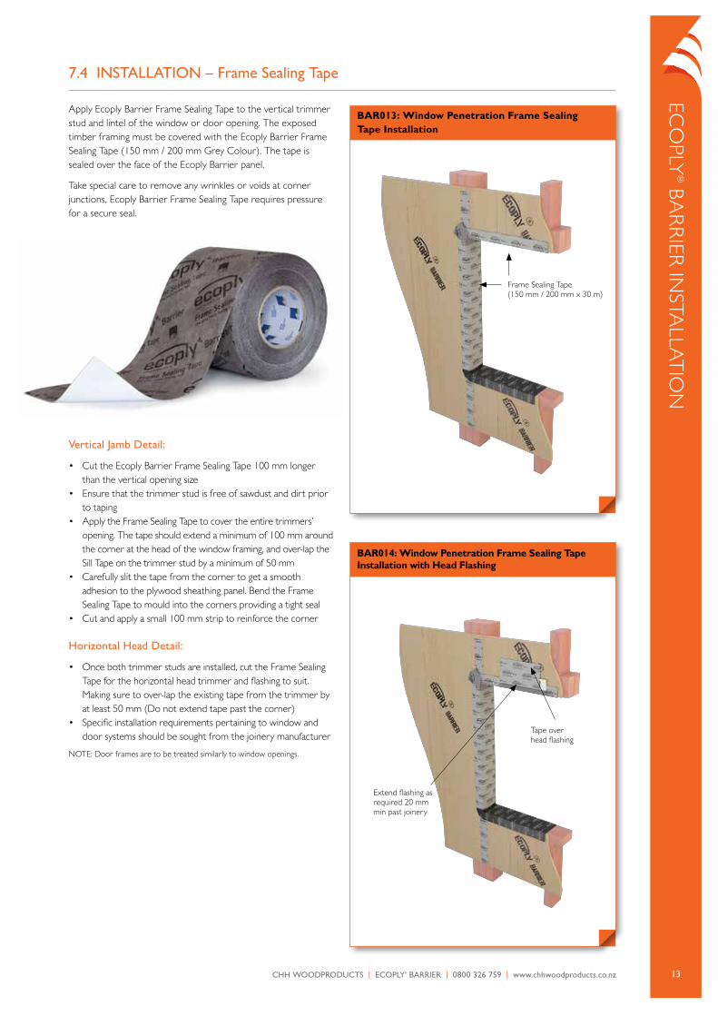
BAR013: Window Penetration Frame Sealing Tape Installation
BAR014: Window Penetration Frame Sealing Tape Installation with Head Flashing
7.4 InSTALLATIon – Frame Sealing Tape
apply Ecoply Barrier Frame Sealing Tape to the vertical trimmer stud and lintel of the window or door opening. The exposed timber framing must be covered with the Ecoply Barrier Frame Sealing Tape (150 mm / 200 mm Grey colour). The tape is sealed over the face of the Ecoply Barrier panel.
Take special care to remove any wrinkles or voids at corner junctions, Ecoply Barrier Frame Sealing Tape requires pressure for a secure seal.
Eco
ply® Ba
rr
iEr iN
STalla
Tio
N
Frame Sealing Tape (150 mm / 200 mm x 30 m)
Vertical Jamb Detail:
• cut the Ecoply Barrier Frame Sealing Tape 100 mm longer than the vertical opening size
• Ensure that the trimmer stud is free of sawdust and dirt prior to taping
• apply the Frame Sealing Tape to cover the entire trimmers’ opening. The tape should extend a minimum of 100 mm around the corner at the head of the window framing, and over-lap the Sill Tape on the trimmer stud by a minimum of 50 mm
• carefully slit the tape from the corner to get a smooth adhesion to the plywood sheathing panel. Bend the Frame Sealing Tape to mould into the corners providing a tight seal
• cut and apply a small 100 mm strip to reinforce the corner
Horizontal Head Detail:
• once both trimmer studs are installed, cut the Frame Sealing Tape for the horizontal head trimmer and flashing to suit. Making sure to over-lap the existing tape from the trimmer by at least 50 mm (Do not extend tape past the corner)
• Specific installation requirements pertaining to window and door systems should be sought from the joinery manufacturer
NoTE: Door frames are to be treated similarly to window openings.
Tape over head flashing
Extend flashing as required 20 mm min past joinery
14 CHH WoodproduCts | ECoply® BarriEr | 0800 326 759 | www.chhwoodproducts.co.nz
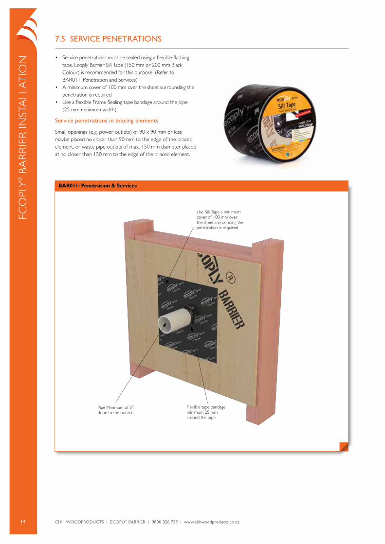
7.5 SERVICE PEnETRATIonS
• Service penetrations must be sealed using a flexible flashing tape. Ecoply Barrier Sill Tape (150 mm or 200 mm Black colour) is recommended for this purpose. (refer to Bar011: penetration and Services)
• a minimum cover of 100 mm over the sheet surrounding the penetration is required
• Use a flexible Frame Sealing tape bandage around the pipe (25 mm minimum width)
Service penetrations in bracing elements
Small openings (e.g. power outlets) of 90 x 90 mm or less maybe placed no closer than 90 mm to the edge of the braced element, or waste pipe outlets of max. 150 mm diameter placed at no closer than 150 mm to the edge of the braced element.
Eco
ply
® B
ar
riE
r iN
STa
lla
Tio
N
BAR011: Penetration & Services
Use Sill Tape a minimum cover of 100 mm over the sheet surrounding the penetration is required
pipe Minimum of 5º slope to the outside
Flexible tape bandage minimum 25 mm around the pipe
15CHH WoodproduCts | ECoply® BarriEr | 0800 326 759 | www.chhwoodproducts.co.nz
Eco
ply® Ba
rr
iEr iN
STalla
Tio
N
TABLE 4: SuMMARy P21 RATInGS FoR 2.4 M HIGH ECoPLy® BARRIER WALL ELEMEnTS
Specification No. Minimum Wall Length Lining Requirements Hold Down BUs/m
WindBUs/m
Earthquake
EPB1
0.4 m
Ecoply® Barrier one sideyes
GIB HandiBrac®
80 95
0.6 m 95 105
1.2 m 120 135
EPBS
0.4 m
Ecoply® Barrier one side no additional fastening 1
60 60
0.6 m 60 65
1.2 m 65 70
2.4 m 80 90
EPBG0.4 m Ecoply® Barrier one side and
10 mm GIB® Standard plasterboard other side
yesGIB HandiBrac®
100 115
1.2 m 150 150
1 as per NZS 3604: 2011. No specific additional fastening required.
7.6 STRuCTuRAL BRACInG
Designed to comply with the NZBc.
Structure
NZS 3604 Timber Framed Buildings is listed as an acceptable Solution under clause 3.0 Timber in acceptable Solution B1/aS1 Structure. cHH Woodproducts have developed a range of wall bracing elements tested using p21 testing methods referenced in NZS 3604.
Demand may be calculated by following section 5, Bracing Design of NZS 3604 or using the GiB EzyBrace® software, downloadable from www.gib.co.nz
EpB bracing systems properties can be easily loaded into the EzyBrace software by way of an Excel patch downloadable from www.chhwoodproducts.co.nz together with loading instructions.
Specific design
Ecoply Barrier structural plywood is manufactured to aS/NZS 2269, and it is suitable for design and use in earthquake and wind bracing systems constructed in accordance with NZS 3603 and aS/NZS 1170.
Structural plywood to aS/NZS 2269 is the only sheet brace material with properties defined in a published New Zealand engineering design code, NZS 3603 Timber Structures, and so can be designed in compliance with Verification method B1/VM1 under clause 6.0 Timber for use in buildings over three storeys in height.
Timber Floors
When carrying out a bracing design for buildings with timber floor structures, the maximum bracing rating that can be accounted for when summing up the bracing units is 120 BUs/m. This does not exclude the installation of bracing elements that are rated higher than 120 BUs/m, however the extra bracing capacity can not be accounted for in the bracing design.
Specific design of floor and sub-floor framing is required for elements rated higher than 120 BUs/m.
Durability
Ecoply Barrier plywood is manufactured to meet the requirements of NZS 3602 Timber and Wood based products for use in Buildings. if the product is used, handled and installed in accordance with cHH Woodproducts product literature it will meet the durability requirements of the NZBc.
Adjustments for wall height
Use section 5 of NZS 3604 or GiB EzyBrace software to calculate bracing values:
adjustment of bracing capacity of walls of different heights and walls with sloping top plates shall be obtained by the following method:
(a) For wall bracing elements of heights other than 2.4 m, the bracing rating determined by test or from table below should be multiplied by 2.4 ÷ element height in metres, except that elements less than 2.4 m high shall be rated as if they are 2.4 m high.
(b) Walls of varying heights, should have their bracing capacity adjusted in accordance with section 5 of NZS 3604 using the average height.
(c) Wall heights <1.5 m are to be subject to Specific Engineer Design (SED)
Joining panels for walls higher than maximum sheet length
Ecoply Barrier bracing panels must be fixed from top plate to bottom plate. For wall heights over 2.44 m, Ecoply Barrier is available in 2.745 m sheet lengths. alternatively, a part sheet can be stacked above a full sheet, butt joined on a single row of nogs with each sheet/part sheet independently nailed off as per the nail spacing in the Ecoply Barrier bracing specifications (e.g. 2.4 m x 1.2 m sheet with a 0.3 m x 1.2 m part sheet above it to give a 2.7 m x 1.2 m bracing element).
16 CHH WoodproduCts | ECoply® BarriEr | 0800 326 759 | www.chhwoodproducts.co.nz
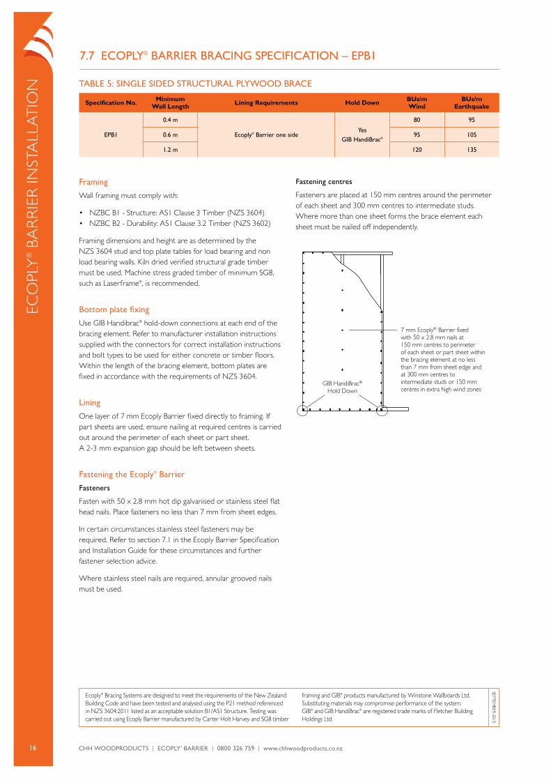
7.7 ECoPLy® BARRIER BRACInG SPECIFICATIon – EPB1
Eco
ply
® B
ar
riE
r iN
STa
lla
Tio
N
Framing
Wall framing must comply with:
• NZBc B1 - Structure: aS1 clause 3 Timber (NZS 3604)• NZBc B2 - Durability: aS1 clause 3.2 Timber (NZS 3602)
Framing dimensions and height are as determined by the NZS 3604 stud and top plate tables for load bearing and non load bearing walls. Kiln dried verified structural grade timber must be used. Machine stress graded timber of minimum SG8, such as laserframe®, is recommended.
Bottom plate fixing
Use GiB Handibrac® hold-down connections at each end of the bracing element. refer to manufacturer installation instructions supplied with the connectors for correct installation instructions and bolt types to be used for either concrete or timber floors. Within the length of the bracing element, bottom plates are fixed in accordance with the requirements of NZS 3604.
Lining
one layer of 7 mm Ecoply Barrier fixed directly to framing. if part sheets are used, ensure nailing at required centres is carried out around the perimeter of each sheet or part sheet. a 2-3 mm expansion gap should be left between sheets.
Fastening the Ecoply® Barrier
Fasteners
Fasten with 50 x 2.8 mm hot dip galvanised or stainless steel flat head nails. place fasteners no less than 7 mm from sheet edges.
in certain circumstances stainless steel fasteners may be required. refer to section 7.1 in the Ecoply Barrier Specification and installation Guide for these circumstances and further fastener selection advice.
Where stainless steel nails are required, annular grooved nails must be used.
Fastening centres
Fasteners are placed at 150 mm centres around the perimeter of each sheet and 300 mm centres to intermediate studs. Where more than one sheet forms the brace element each sheet must be nailed off independently.
7 mm Ecoply® Barrier fixed with 50 x 2.8 mm nails at 150 mm centres to perimeter of each sheet or part sheet within the bracing element at no less than 7 mm from sheet edge and at 300 mm centres to intermediate studs or 150 mm centres in extra high wind zones
GIB HandiBrac® Hold Down
Ecoply® Bracing Systems are designed to meet the requirements of the New Zealand Building code and have been tested and analysed using the p21 method referenced in NZS 3604:2011 listed as an acceptable solution B1/aS1 Structure. Testing was carried out using Ecoply Barrier manufactured by carter Holt Harvey and SG8 timber
framing and GiB® products manufactured by Winstone Wallboards ltd. Substituting materials may compromise performance of the system. GiB® and GiB HandiBrac® are registered trade marks of Fletcher Building Holdings ltd.
SEpTEMBEr 2015
TABLE 5: SInGLE SIDED STRuCTuRAL PLyWooD BRACE
Specification No. Minimum Wall Length Lining Requirements Hold Down BUs/m
WindBUs/m
Earthquake
EPB1
0.4 m
Ecoply® Barrier one sideyes
GIB HandiBrac®
80 95
0.6 m 95 105
1.2 m 120 135
17CHH WoodproduCts | ECoply® BarriEr | 0800 326 759 | www.chhwoodproducts.co.nz
Eco
ply® Ba
rr
iEr iN
STalla
Tio
N
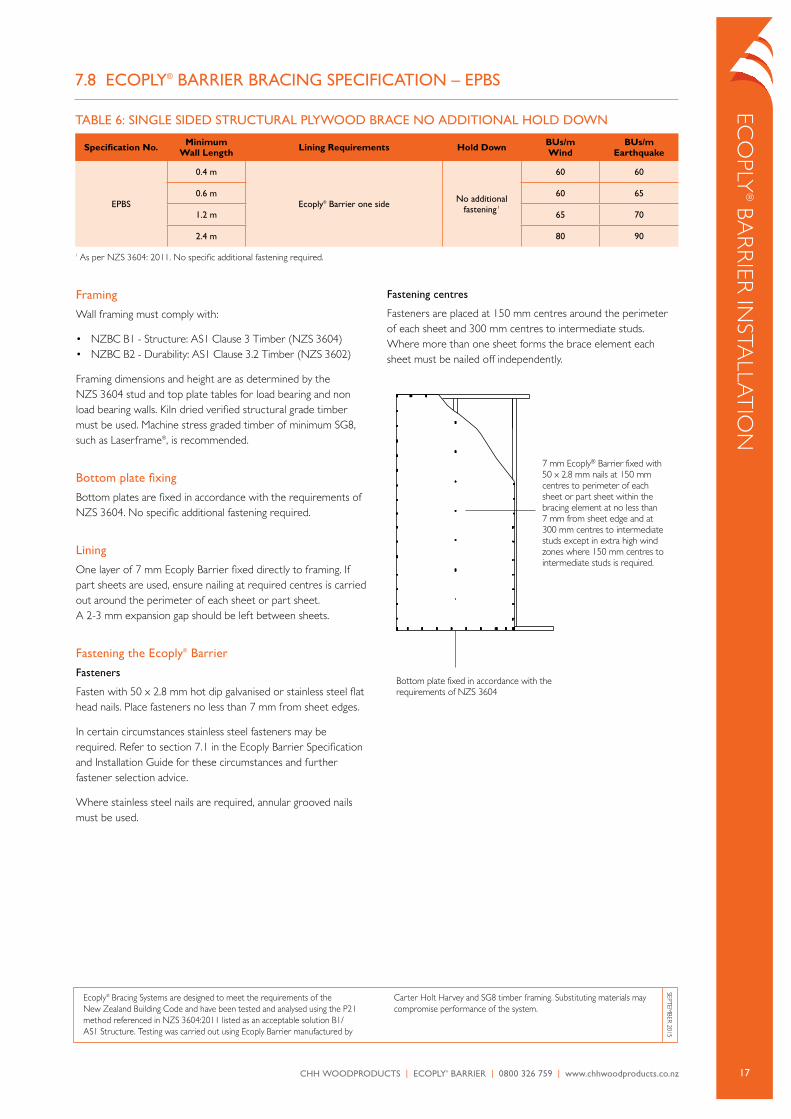
7.8 ECoPLy® BARRIER BRACInG SPECIFICATIon – EPBS
Framing
Wall framing must comply with:
• NZBc B1 - Structure: aS1 clause 3 Timber (NZS 3604)• NZBc B2 - Durability: aS1 clause 3.2 Timber (NZS 3602)
Framing dimensions and height are as determined by the NZS 3604 stud and top plate tables for load bearing and non load bearing walls. Kiln dried verified structural grade timber must be used. Machine stress graded timber of minimum SG8, such as laserframe®, is recommended.
Bottom plate fixing
Bottom plates are fixed in accordance with the requirements of NZS 3604. No specific additional fastening required.
Lining
one layer of 7 mm Ecoply Barrier fixed directly to framing. if part sheets are used, ensure nailing at required centres is carried out around the perimeter of each sheet or part sheet. a 2-3 mm expansion gap should be left between sheets.
Fastening the Ecoply® Barrier
Fasteners
Fasten with 50 x 2.8 mm hot dip galvanised or stainless steel flat head nails. place fasteners no less than 7 mm from sheet edges.
in certain circumstances stainless steel fasteners may be required. refer to section 7.1 in the Ecoply Barrier Specification and installation Guide for these circumstances and further fastener selection advice.
Where stainless steel nails are required, annular grooved nails must be used.
Fastening centres
Fasteners are placed at 150 mm centres around the perimeter of each sheet and 300 mm centres to intermediate studs. Where more than one sheet forms the brace element each sheet must be nailed off independently.
7 mm Ecoply® Barrier fixed with 50 x 2.8 mm nails at 150 mm centres to perimeter of each sheet or part sheet within the bracing element at no less than 7 mm from sheet edge and at 300 mm centres to intermediate studs except in extra high wind zones where 150 mm centres to intermediate studs is required.
Bottom plate fixed in accordance with the requirements of NZS 3604
Ecoply® Bracing Systems are designed to meet the requirements of the New Zealand Building code and have been tested and analysed using the p21 method referenced in NZS 3604:2011 listed as an acceptable solution B1/aS1 Structure. Testing was carried out using Ecoply Barrier manufactured by
carter Holt Harvey and SG8 timber framing. Substituting materials may compromise performance of the system.
SEpTEMBEr 2015
TABLE 6: SInGLE SIDED STRuCTuRAL PLyWooD BRACE no ADDITIonAL HoLD DoWn
Specification No. Minimum Wall Length Lining Requirements Hold Down BUs/m
WindBUs/m
Earthquake
EPBS
0.4 m
Ecoply® Barrier one side no additional fastening 1
60 60
0.6 m 60 65
1.2 m 65 70
2.4 m 80 90
1 as per NZS 3604: 2011. No specific additional fastening required.
18 CHH WoodproduCts | ECoply® BarriEr | 0800 326 759 | www.chhwoodproducts.co.nz
Framing
Wall framing must comply with:
• NZBc B1 - Structure: aS1 clause 3 Timber (NZS 3604)• NZBc B2 - Durability: aS1 clause 3.2 Timber (NZS 3602)
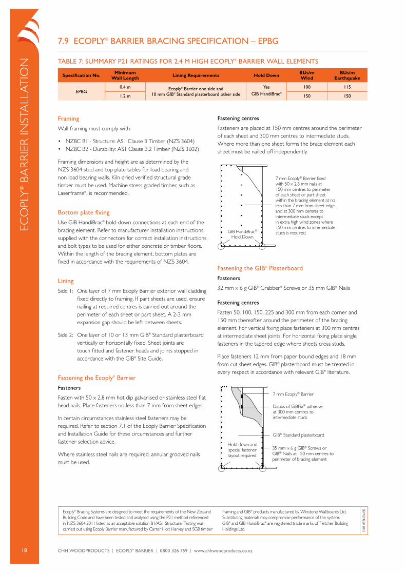
Framing dimensions and height are as determined by the NZS 3604 stud and top plate tables for load bearing and non load bearing walls. Kiln dried verified structural grade timber must be used. Machine stress graded timber, such as laserframe®, is recommended.
Bottom plate fixing
Use GiB HandiBrac® hold-down connections at each end of the bracing element. refer to manufacturer installation instructions supplied with the connectors for correct installation instructions and bolt types to be used for either concrete or timber floors. Within the length of the bracing element, bottom plates are fixed in accordance with the requirements of NZS 3604.
Lining
Side 1: one layer of 7 mm Ecoply Barrier exterior wall cladding fixed directly to framing. if part sheets are used, ensure nailing at required centres is carried out around the perimeter of each sheet or part sheet. a 2-3 mm expansion gap should be left between sheets.
Side 2: one layer of 10 or 13 mm GiB® Standard plasterboard vertically or horizontally fixed. Sheet joints are touch fitted and fastener heads and joints stopped in accordance with the GiB® Site Guide.
Fastening the Ecoply® Barrier
Fasteners
Fasten with 50 x 2.8 mm hot dip galvanised or stainless steel flat head nails. place fasteners no less than 7 mm from sheet edges.
in certain circumstances stainless steel fasteners may be required. refer to section 7.1 of the Ecoply Barrier Specification and installation Guide for these circumstances and further fastener selection advice.
Where stainless steel nails are required, annular grooved nails must be used.
Fastening centres
Fasteners are placed at 150 mm centres around the perimeter of each sheet and 300 mm centres to intermediate studs. Where more than one sheet forms the brace element each sheet must be nailed off independently.
7 mm Ecoply® Barrier fixed with 50 x 2.8 mm nails at 150 mm centres to perimeter of each sheet or part sheet within the bracing element at no less than 7 mm from sheet edge and at 300 mm centres to intermediate studs except in extra high wind zones where 150 mm centres to intermediate studs is required.GIB HandiBrac®
Hold Down
7.9 ECoPLy® BARRIER BRACInG SPECIFICATIon – EPBG
Ecoply® Bracing Systems are designed to meet the requirements of the New Zealand Building code and have been tested and analysed using the p21 method referenced in NZS 3604:2011 listed as an acceptable solution B1/aS1 Structure. Testing was carried out using Ecoply Barrier manufactured by carter Holt Harvey and SG8 timber
framing and GiB® products manufactured by Winstone Wallboards ltd. Substituting materials may compromise performance of the system. GiB® and GiB HandiBrac® are registered trade marks of Fletcher Building Holdings ltd.
SEpTEMBEr 2015
Fastening the GIB® Plasterboard
Fasteners
32 mm x 6 g GiB® Grabber® Screws or 35 mm GiB® Nails
Fastening centres
Fasten 50, 100, 150, 225 and 300 mm from each corner and 150 mm thereafter around the perimeter of the bracing element. For vertical fixing place fasteners at 300 mm centres at intermediate sheet joints. For horizontal fixing place single fasteners in the tapered edge where sheets cross studs.
place fasteners 12 mm from paper bound edges and 18 mm from cut sheet edges. GiB® plasterboard must be treated in every respect in accordance with relevant GiB® literature.
35 mm x 6 g GIB® Screws or GIB® Nails at 150 mm centres to perimeter of bracing element
Hold-down and special fastener layout required
GIB® Standard plasterboard
Daubs of GIBFix® adhesive at 300 mm centres to intermediate studs
7 mm Ecoply® Barrier
Eco
ply
® B
ar
riE
r iN
STa
lla
Tio
N TABLE 7: SuMMARy P21 RATInGS FoR 2.4 M HIGH ECoPLy® BARRIER WALL ELEMEnTS
Specification No. Minimum Wall Length Lining Requirements Hold Down BUs/m
WindBUs/m
Earthquake
EPBG0.4 m Ecoply® Barrier one side and
10 mm GIB® Standard plasterboard other side
yesGIB HandiBrac®
100 115
1.2 m 150 150
19CHH WoodproduCts | ECoply® BarriEr | 0800 326 759 | www.chhwoodproducts.co.nz
Eco
ply® Ba
rr
iEr iN
STalla
Tio
N
Ecoply® Bracing Systems are designed to meet the requirements of the New Zealand Building code and have been tested and analysed using the p21 method referenced in NZS 3604:2011 listed as an acceptable solution B1/aS1 Structure. Testing was carried out using Ecoply Barrier manufactured by carter Holt Harvey and SG8 timber
framing and GiB® products manufactured by Winstone Wallboards ltd. Substituting materials may compromise performance of the system. GiB® and GiB HandiBrac® are registered trade marks of Fletcher Building Holdings ltd.
SEpTEMBEr 2015
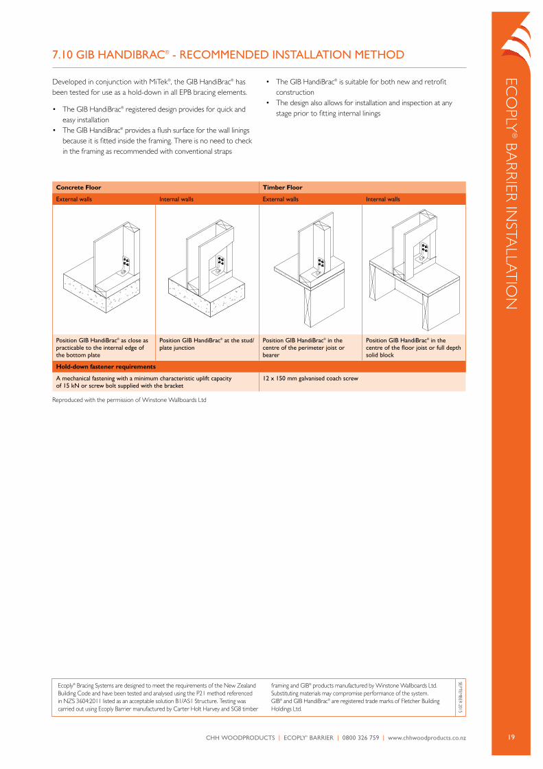
7.10 GIB HAnDIBRAC® - RECoMMEnDED InSTALLATIon METHoD
Developed in conjunction with MiTek®, the GiB HandiBrac® has been tested for use as a hold-down in all EpB bracing elements.
• The GiB HandiBrac® registered design provides for quick and easy installation
• The GiB HandiBrac® provides a flush surface for the wall linings because it is fitted inside the framing. There is no need to check in the framing as recommended with conventional straps
• The GiB HandiBrac® is suitable for both new and retrofit construction
• The design also allows for installation and inspection at any stage prior to fitting internal linings
Concrete Floor Timber Floor
External walls Internal walls External walls Internal walls
Position GIB HandiBrac® as close as practicable to the internal edge of the bottom plate
Position GIB HandiBrac® at the stud/plate junction
Position GIB HandiBrac® in the centre of the perimeter joist or bearer
Position GIB HandiBrac® in the centre of the floor joist or full depth solid block
Hold-down fastener requirements
A mechanical fastening with a minimum characteristic uplift capacity of 15 kn or screw bolt supplied with the bracket
12 x 150 mm galvanised coach screw
reproduced with the permission of Winstone Wallboards ltd
20 CHH WoodproduCts | ECoply® BarriEr | 0800 326 759 | www.chhwoodproducts.co.nz
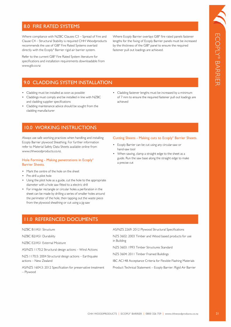
Figure 2: Lintel Connection Detail (For Uplifts Not Exceeding 7.5 kN) as detailed in Clause 8.6.1.8 of NZS 3604
Eco
ply
® B
ar
riE
r iN
STa
lla
Tio
N
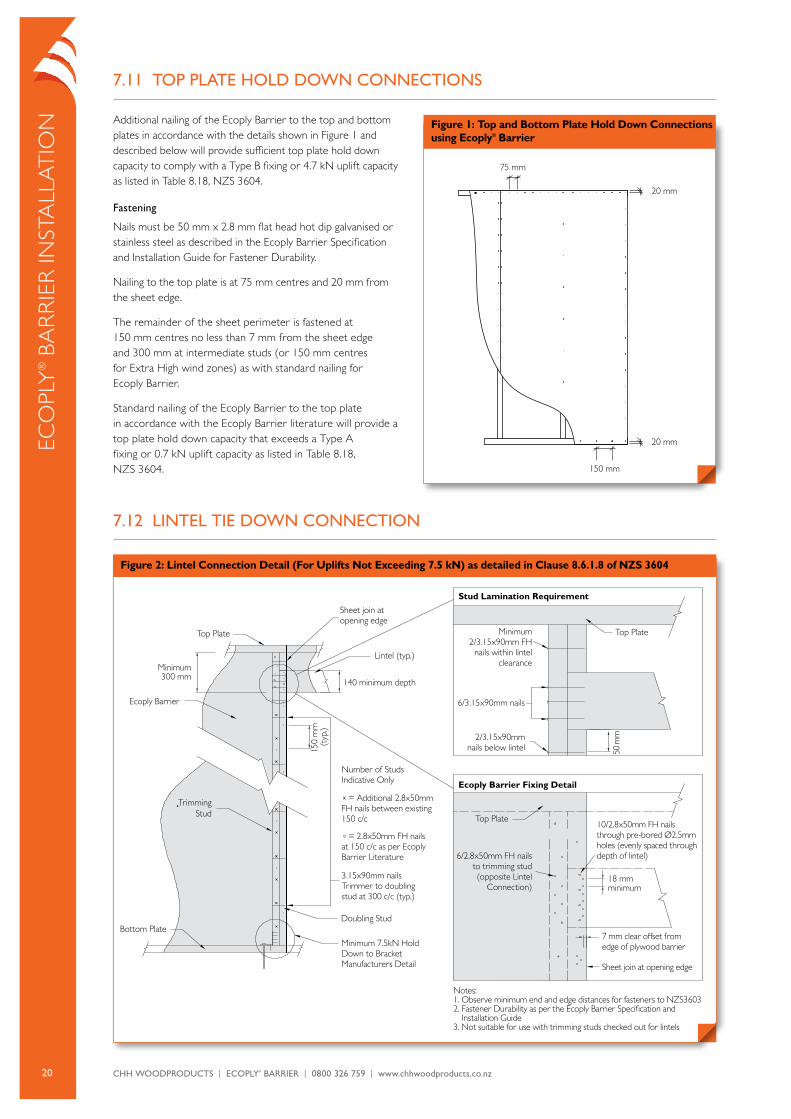
7.11 ToP PLATE HoLD DoWn ConnECTIonS
additional nailing of the Ecoply Barrier to the top and bottom plates in accordance with the details shown in Figure 1 and described below will provide sufficient top plate hold down capacity to comply with a Type B fixing or 4.7 kN uplift capacity as listed in Table 8.18, NZS 3604.
Fastening
Nails must be 50 mm x 2.8 mm flat head hot dip galvanised or stainless steel as described in the Ecoply Barrier Specification and installation Guide for Fastener Durability.
Nailing to the top plate is at 75 mm centres and 20 mm from the sheet edge.
The remainder of the sheet perimeter is fastened at 150 mm centres no less than 7 mm from the sheet edge and 300 mm at intermediate studs (or 150 mm centres for Extra High wind zones) as with standard nailing for Ecoply Barrier.
Standard nailing of the Ecoply Barrier to the top plate in accordance with the Ecoply Barrier literature will provide a top plate hold down capacity that exceeds a Type a fixing or 0.7 kN uplift capacity as listed in Table 8.18, NZS 3604.
7.12 LInTEL TIE DoWn ConnECTIon
Figure 1: Top and Bottom Plate Hold Down Connections using Ecoply® Barrier
75 mm
20 mm
150 mm
20 mm
Lintel (typ.)
18 mm minimum
140 minimum depth
Sheet join at opening edge
Ecoply Barrier
Minimum 300 mm
Trimming Stud
Bottom Plate
Top Plate Top Plate
Top Plate
Doubling Stud
Minimum 7.5kN Hold Down to Bracket Manufacturers Detail
6/2.8x50mm FH nails to trimming stud (opposite Lintel
Connection)
7 mm clear o�set from edge of plywood barrier
Sheet join at opening edge
10/2.8x50mm FH nails through pre-bored Ø2.5mm holes (evenly spaced through depth of lintel)
Notes:1. Observe minimum end and edge distances for fasteners to NZS36032. Fastener Durability as per the Ecoply Barrier Specification and Installation Guide3. Not suitable for use with trimming studs checked out for lintels
Number of Studs Indicative Only
= 2.8x50mm FH nails at 150 c/c as per Ecoply Barrier Literature
3.15x90mm nails Trimmer to doubling stud at 300 c/c (typ.)
= Additional 2.8x50mm FH nails between existing 150 c/c
Minimum 2/3.15x90mm FH
nails within lintel clearance
Stud Lamination Requirement
Ecoply Barrier Fixing Detail
6/3.15x90mm nails
2/3.15x90mm nails below lintel
21CHH WoodproduCts | ECoply® BarriEr | 0800 326 759 | www.chhwoodproducts.co.nz
Eco
ply® Ba
rr
iEr
Where compliance with NZBc clauses c3 – Spread of Fire and clause c4 – Structural Stability is required cHH Woodproducts recommends the use of GiB® Fire rated Systems overlaid directly with the Ecoply® Barrier rigid air barrier system.
refer to the current GiB® Fire rated System literature for specifications and installation requirements downloadable from www.gib.co.nz
Where Ecoply Barrier overlays GiB® fire rated panels fastener lengths for the fixing of Ecoply Barrier panels must be increased by the thickness of the GiB® panel to ensure the required fastener pull out loadings are achieved.
8.0 FIRE RATED SySTEMS
• cladding must be installed as soon as possible• claddings must comply and be installed in line with NZBc
and cladding supplier specifications• cladding maintenance advice should be sought from the
cladding manufacturer
• cladding fastener lengths must be increased by a minimum of 7 mm to ensure the required fastener pull out loadings are achieved
9.0 CLADDInG SySTEM InSTALLATIon
always use safe working practices when handling and installing Ecoply Barrier plywood Sheathing. For further information refer to Material Safety Data Sheets available online from www.chhwoodproducts.co.nz.
Hole Forming - Making penetrations in Ecoply® Barrier Sheets.
• Mark the centre of the hole on the sheet• pre drill a pilot hole• Using the pilot hole as a guide, cut the hole to the appropriate
diameter with a hole saw fitted to a electric drill• For irregular rectangle or circular holes a perforation in the
sheet can be made by drilling a series of smaller holes around the perimeter of the hole, then tapping out the waste piece from the plywood sheathing or cut using a jig-saw
Cutting Sheets - Making cuts to Ecoply® Barrier Sheets.
• Ecoply Barrier can be cut using any circular-saw or hand-saw tool
• When sawing, clamp a straight edge to the sheet as a guide. run the saw base along the straight edge to make a precise cut
10.0 WoRKInG InSTRuCTIonS
NZBc B1/aS1 Structure
NZBc B2/aS1 Durability
NZBc E2/aS1 External Moisture
aS/NZS 1170.2 Structural design actions – Wind actions
NZS 1170.5: 2004 Structural design actions – Earthquake actions – New Zealand
aS/NZS 1604.3: 2012 Specification for preservative treatment – plywood
aS/NZS 2269: 2012 plywood Structural Specifications
NZS 3602: 2003 Timber and Wood based products for use in Building
NZS 3603: 1993 Timber Structures Standard
NZS 3604: 2011 Timber Framed Buildings
iBc ac148 acceptance criteria for Flexible Flashing Materials
product Technical Statement – Ecoply Barrier: rigid air Barrier
11.0 REFEREnCED DoCuMEnTS
22 CHH WoodproduCts | ECoply® BarriEr | 0800 326 759 | www.chhwoodproducts.co.nz
Eco
ply
® B
ar
riE
r Q. Do fastener heads need to be taped over?
a. Fastener heads are not required to be taped over, unless the fastener head completely penetrates the thickness of the face veneer.
Q. Do I need to tape all of the seams between the Ecoply® Barrier plywood panels?
a. yes. all seams between the panels must be taped with the Ecoply Barrier Sealing Tape (60 mm width Grey colour) to ensure that it functions as a structural rigid air barrier system.
Q. Can Ecoply Barrier Sealing Tape, Sill Tape and Frame Sealing Tape be installed in the rain?
a. yes. The tapes require pressure for a secure seal, and will require an extra period of time to fully adhere to the surface.
Q. What is permeance, and why is it important?
a. permeance is a property that defines the ease at which water molecules diffuse through a material, typically measured in “perms.” While water resistive barriers are designed to keep liquid water out of the wall system, they are also generally designed to allow moisture vapour to pass through so that the wall system can “breathe” meaning moisture vapor will not accumulate and condense in the wall system.
Q. How long can I leave Ecoply Barrier panels exposed before I install roof and wall coverings?
a. Ecoply Barrier panels can be left exposed for up to 90 days, however it is recommended to install roof and wall coverings aSap.
Q. What is the weight of an Ecoply Barrier panel?
a. 2440 mm panel = 11.7 kg, 2745 mm panel = 13.2 kg (guidelines only)
Q. What is the R-value of Ecoply Barrier?
a. The thermal resistance or insulating effectiveness of plywood panels can be calculated using NZS 4214. plywood has a conductivity (K) of 0.13 W/mc so a 7 mm panel has a thermal resistance r = 0.007/0.13 = 0.05
Q. How much space should be left for expansion?
a. allow 2-3 mm expansion gap between square edges of Ecoply Barrier panels. Ecoply Barrier is provided in 1197 mm widths to account for this.
Q. Where can I purchase Ecoply Barrier panels and tapes from?
a. The Ecoply Barrier system is available from all leading building merchants in NZ.
Q. Where can I locate information on steel framing insulation?
a. Steel frame specification documents can be downloaded at www.nashnz.org.nz
12.0 FREQuEnTLy ASKED QuESTIonS
The information contained in this document is current as at September 2015 and is based on data available to cHH Woodproducts at the time of going to print.
all photographic images are intended to provide a general impression only and should not be relied upon as an accurate example of Ecoply Barrier products installed in accordance with this document or the NZBc compliance documents.
This publication replaces all previous cHH Woodproducts’ design information and literature relating to Ecoply Barrier structural plywood products and tapes. cHH Woodproducts reserves the right to change the information contained in this document
without prior notice. it is your responsibility to ensure that you have the most up to date information available, including at the time of applying for a building consent. you can call toll free on 0800 326 759 or visit www.chhwoodproducts.co.nz to obtain current information.
CHH Woodproducts has used all reasonable endeavours to ensure the accuracy and reliability of the information contained in this document. However, to the maximum extent permitted by law, CHH Woodproducts assumes no responsibility or liability for any inaccuracies, omissions or errors in this information nor for any actions taken in reliance on this information.
13.0 LIMITATIonS
23CHH WoodproduCts | ECoply® BarriEr | 0800 326 759 | www.chhwoodproducts.co.nz
Eco
ply® Ba
rr
iEr iN
STalla
Tio
N c
HEc
K liST
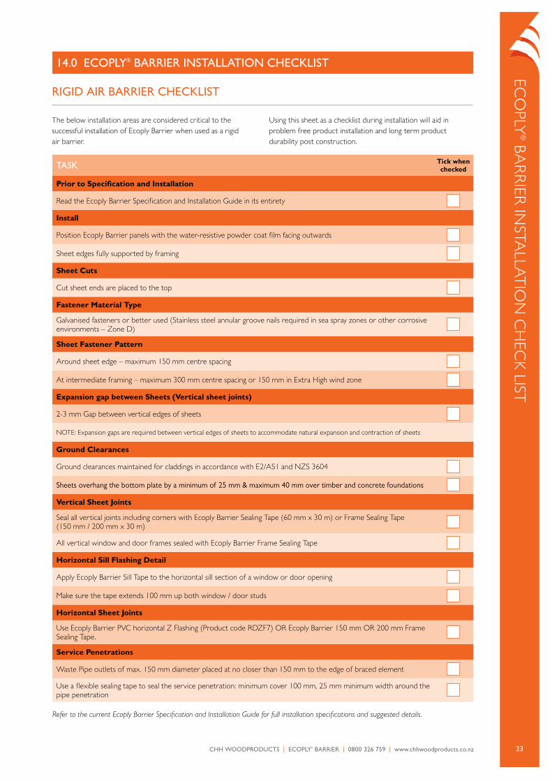
14.0 ECoPLy® BARRIER InSTALLATIon CHECKLIST
RIGID AIR BARRIER CHECKLIST
The below installation areas are considered critical to the successful installation of Ecoply Barrier when used as a rigid air barrier.
Using this sheet as a checklist during installation will aid in problem free product installation and long term product durability post construction.
TASK Tick when checked
Prior to Specification and Installation
read the Ecoply Barrier Specification and installation Guide in its entirety
Install
position Ecoply Barrier panels with the water-resistive powder coat film facing outwards
Sheet edges fully supported by framing
Sheet Cuts
cut sheet ends are placed to the top
Fastener Material Type
Galvanised fasteners or better used (Stainless steel annular groove nails required in sea spray zones or other corrosive environments – Zone D)
Sheet Fastener Pattern
around sheet edge – maximum 150 mm centre spacing
at intermediate framing – maximum 300 mm centre spacing or 150 mm in Extra High wind zone
Expansion gap between Sheets (Vertical sheet joints)
2-3 mm Gap between vertical edges of sheets
NoTE: Expansion gaps are required between vertical edges of sheets to accommodate natural expansion and contraction of sheets
Ground Clearances
Ground clearances maintained for claddings in accordance with E2/aS1 and NZS 3604
Sheets overhang the bottom plate by a minimum of 25 mm & maximum 40 mm over timber and concrete foundations
Vertical Sheet Joints
Seal all vertical joints including corners with Ecoply Barrier Sealing Tape (60 mm x 30 m) or Frame Sealing Tape (150 mm / 200 mm x 30 m)
all vertical window and door frames sealed with Ecoply Barrier Frame Sealing Tape
Horizontal Sill Flashing Detail
apply Ecoply Barrier Sill Tape to the horizontal sill section of a window or door opening
Make sure the tape extends 100 mm up both window / door studs
Horizontal Sheet Joints
Use Ecoply Barrier pVc horizontal Z Flashing (product code rDZF7) or Ecoply Barrier 150 mm or 200 mm Frame Sealing Tape.
Service Penetrations
Waste pipe outlets of max. 150 mm diameter placed at no closer than 150 mm to the edge of braced element
Use a flexible sealing tape to seal the service penetration: minimum cover 100 mm, 25 mm minimum width around the pipe penetration
Refer to the current Ecoply Barrier Specification and Installation Guide for full installation specifications and suggested details.

Private Bag 92-106Victoria Street WestAuckland 1142new Zealand
Freephone: 0800 326 759Freefax: 0800 746 400
www.chhwoodproducts.co.nz
September 2015
New ZealandManufactured