Banner - 2010 Catalog (Pg 56-85) Miniature Sensors 12850_02
30
More information online at bannerengineering.com SENSORS MINIATURE COMPACT MIDSIZE FULLSIZE 56 More information online at bannerengineering.com Photoelectric page 64 • Miniature 65 • Compact 87 • Midsize 145 • Fullsize 185 Special Purpose page 262 • Part & Area 263 • Slot & Label 266 • Registration Mark & Color 275 • Luminescence 283 • Optical Touch Buttons 290 Fiber Optic Sensors page 219 • Fiber Sensors 219 • Plastic Fibers 239 • Glass Fibers 256 Measurement & Inspection page 297 • Light Gauging 301 • Ultrasonic 312 • Measuring Array 344 • Radar 358
-
Upload
veederline -
Category
Documents
-
view
217 -
download
0
description
Miniature Sensors. Applications: - Measurement and Inspection p 297 • Light Gauging p301 • Ultrasonic p312 • Measuring Array p344 • Radar p358 MINIATURE COMPACT MIDSIZE FULLSIZE Special Purpose page p262 • Part and Area p263 • Slot and Label p266 • Registration Mark and Color p275 • Luminescence p283 • Optical Touch Buttons p290
Transcript of Banner - 2010 Catalog (Pg 56-85) Miniature Sensors 12850_02

More information online at bannerengineering.com
SEN
SOR
SMINIATURE COMPACT MIDSIZE FULLSIZE
56 More information online at bannerengineering.com
Photoelectric page 64
• Miniature 65
• Compact 87
• Midsize 145
• Fullsize 185
Special Purpose page 262
• Part & Area 263
• Slot & Label 266
• Registration Mark & Color 275
• Luminescence 283
• Optical Touch Buttons 290
Fiber Optic Sensors page 219
• Fiber Sensors 219
• Plastic Fibers 239
• Glass Fibers 256
Measurement & Inspection page 297
• Light Gauging 301
• Ultrasonic 312
• Measuring Array 344
• Radar 358

PhotoelectricsSensors
Fiber OpticSensors
Special PurposeSensors
Measurement & Inspection Sensors
Vision
Wireless
Indicators
Safety Light Screens
Safety Laser Scanners
Fiber OpticSafety Systems
Safety Controllers & Modules
Safety Two-Hand Control Modules
Safety Interlock Switches
Emergency Stop Devices
More information online at bannerengineering.com
MINIATURE
COMPACT
MIDSIZE
FULLSIZE
57
Types of Sensors1. Self-contained sensors: One-piece
photoelectric sensors that contain both the optics and the electronics. These sensors perform their
own modulation, demodulation, amplification and output switching.
Right-AngleHousing
2. Remote systems: Sensing systems in which the amplification and the optical sensing are divided. The opto-elements contain only the optical components, allowing the sensing heads to be extremely small. The amplifier module contains the power input, amplification and output switching. This allows the sensitive electronics to be located away from the sensing event.
3. Fiber optic systems: Sensing systems in which fiber optic cables are used with either remote or self-contained sensors. Fiber optic devices have no electrical circuitry and no moving parts, and can be used to safely pipe light into and out of hostile environments.
Basics of Photoelectric Sensing
Amplifier Opto-Elements Fibers
EmitterRadiation Pattern
ReceiverField of View
RECEIVEREMITTER
Effective Beam
How a sensor pair worksA photoelectric sensor is an optical control used in a variety of automated processes. It works by detecting a visible or invisible beam of light, and responding to a change in the received light intensity.
Effective beam: “Working” part of a photoelectric beam.
Radiation pattern: Total area of sensing energy emission.
Field of view: Area of response.
Components of a Sensor Emitter contains the light source, usually an LED, and an oscillator which modulates the LED at a high rate of speed. The emitter sends a modulated light beam to the receiver.
Receiver decodes the light beam and switches an output device that interfaces with the load.
In-Line Housing
ContrastContrast is the ratio of the amount of light falling on a receiver in the “light” state, compared to the “dark” state. Increasing contrast in any sensing situation will increase the reliability of the sensing system.
Beam PatternA beam pattern is plotted on a 2-dimensional graph to illustrate how the sensor responds to its emitter or sensing target. Use the beam pattern to estimate placement of the sensing system with respect to adjacent objects.
Excess GainExcess gain is a measurement of the amount of light falling on a receiver, over and above the amount of light required to operate the sensor.
RangeThe range is the specified operating distance of a sensor or sensing system.
• Opposed mode: The distance from the emitter to the receiver.
• Retroreflective mode: The distance from the sensor to the retroreflector.
• Proximity mode: The distance from the sensor to the object being sensed.
Proximity mode: These sensors contain both emitter and receiver elements. A proximity-mode sensor detects an object when emitted light is reflected off the object, back to the sensor.
Sensing Modes One way to tell sensors apart is by their sensing mode, the method in which a sensor sends and receives light. Photoelectric sensors are divided into three basic sensing modes: opposed, retroreflective and proximity.
Opposed mode: The sensor’s emitter and receiver are housed in two separate units. The emitter is placed opposite the receiver. An object is detected when it breaks the effective beam.
Retroreflective mode: The sensor contains both the emitter and receiver elements. The effective beam is established between the emitter, the retroreflector and the receiver. As with an opposed-mode sensor, an object is sensed when it interrupts or breaks the effective beam.
CONVERGENT
DIFFUSE
FIXED-FIELDBACKGROUNDSUPPRESSION
OPPOSED
RETROREFLECTIVE
DIFFUSE CONVERGENT
DIVERGENT BACKGROUND SUPPRESSION
DIVERGENT
RETROOPPOSED

More information online at bannerengineering.com
SEN
SOR
SMINIATURE COMPACT MIDSIZE FULLSIZE
58
Sensing ModesConfiguration Features Excess Gain Beam Pattern
OPPOSED
• Most reliable mode for opaque targets• High excess gain results in
long sensing range• Good performance in
contaminated environments• High tolerance to misalignment
1
10
100
0.1 m0.33'
1 m3.3'
10 m33'
0.01 m0.03'
1000
EXCESS
GAIN
DISTANCE
3.75 m12.5'
3.0 m10'
2.25 m7.5'
1.5 m5'
.75 m2.5'
0
0
150 mm
300 mm
450 mm
150 mm
300 mm
450 mm
0
6"
12"
18"
6"
12"
18"
DISTANCE
RETROREFLECTIVE
• Convenient when space is limited • High excess gain results in long sensing
range
1
10
100
0.1 m0.33'
1 m3.3'
10 m33'
0.01 m0.03'
1000
EXCESS
GAIN
DISTANCE
with BRT-84 Reflector
3.75 m12.5'
3.0 m10'
2.25 m7.5'
1.5 m5'
.75 m2.5'
0
0
10 mm
20 mm
30 mm
10 mm
20 mm
30 mm
0
0.4"
0.8"
1.2"
0.4"
0.8"
1.2"
DISTANCE
Retroreflective Mode
with BRT-84 Reflector
DIFFUSE
• Convenient when space is limited• Used in applications requiring reflectivity
monitoring
1
10
100
10 mm0.4"
100 mm4.0"
1000 mm40.0"
1 mm0.04"
1000
EXCESS
GAIN
DISTANCE
500 mm20.0"
400mm16.0"
300 mm12.0"
200 mm8.0"
100 mm4.0"
0
0
10 mm
20 mm
30 mm
10 mm
20 mm
30 mm
0
0.4"
0.8"
1.2"
0.4"
0.8"
1.2"
DISTANCE
DIVERGENT• Convenient when space is limited• Good performance in detecting clear
materials at close range• Used in applications requiring reflectivity
monitoring• Reliable in detection of shiny or vibrating
surfaces 1
10
100
10 mm0.4"
100 mm4.0"
1000 mm40.0"
1 mm0.04"
1000
EXCESS
GAIN
DISTANCE
100 mm4.0"
80 mm3.2"
60 mm2.4"
40 mm1.6"
20 mm0.8"
0
0
10 mm
20 mm
30 mm
10 mm
20 mm
30 mm
0
0.4"
0.8"
1.2"
0.4"
0.8"
1.2"
DISTANCE
CONVERGENT• Used for accurate positioning• Excellent in small color mark or small
object detection applications• Used for accurate counting of
radiused objects• High excess gain allows detection
of objects having low reflectivity 1
10
100
10 mm0.4"
100 mm4.0"
1000 mm40.0"
1 mm0.04"
1000
EXCESS
GAIN
DISTANCE
50 mm2.0"
40 mm1.6"
30 mm1.2"
20 mm0.8"
10 mm0.4"
0
0
2 mm
4 mm
6 mm
2 mm
4 mm
6 mm
0
.08"
.16"
.24"
.08"
.16"
.24"
DISTANCE
BACKGROUND SUPPRESSION
• Definite range limit used to ignore backgrounds
• High excess gain allows detection of objects having low reflectivity
• Good at detecting targets of varying reflectivity
1
10
100
1.0 mm0.04"
10.0 mm0.4"
100 mm4.0"
0.1 mm0.004"
1000
EXCESS
GAIN
DISTANCE
PhotoelectricsSensors
Fiber OpticSensors
Special PurposeSensors
Measurement & Inspection Sensors
Vision
Wireless
Indicators
Safety Light Screens
Safety Laser Scanners
Fiber OpticSafety Systems
Safety Controllers & Modules
Safety Two-Hand Control Modules
Safety Interlock Switches
Emergency Stop Devices
More information online at bannerengineering.com
MINIATURE
COMPACT
MIDSIZE
FULLSIZE
59
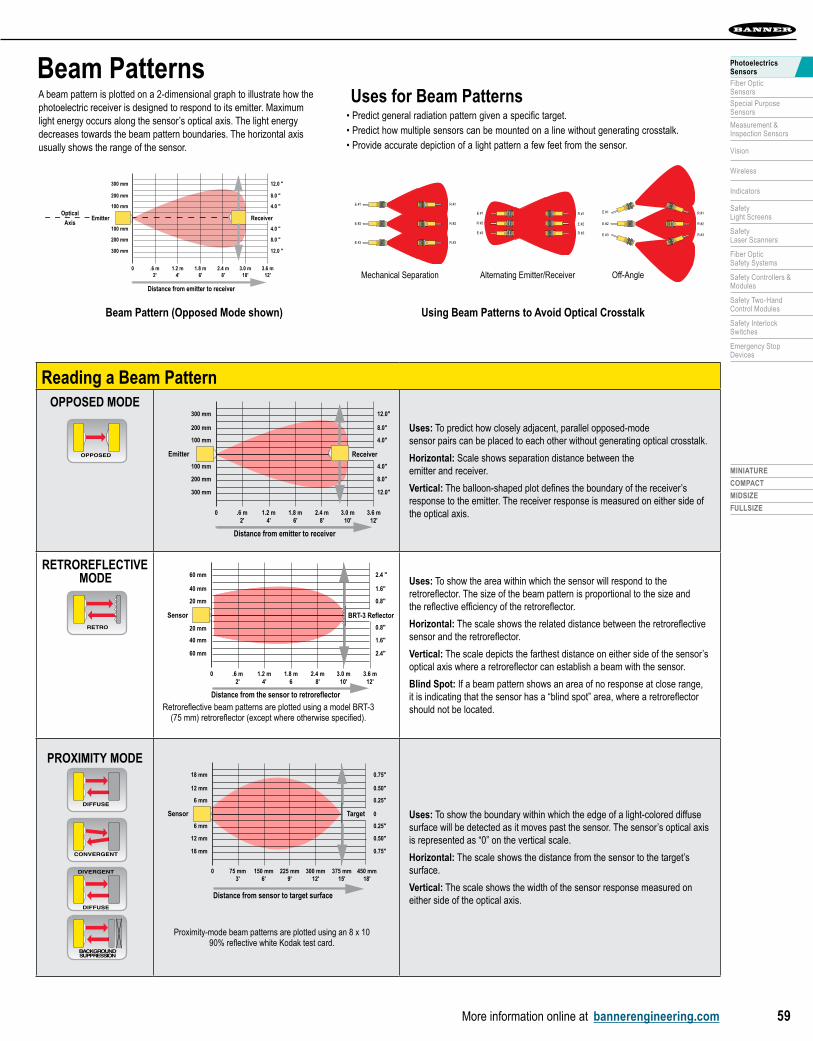
Beam PatternsA beam pattern is plotted on a 2-dimensional graph to illustrate how the photoelectric receiver is designed to respond to its emitter. Maximum light energy occurs along the sensor’s optical axis. The light energy decreases towards the beam pattern boundaries. The horizontal axis usually shows the range of the sensor.
Uses for Beam Patterns• Predict general radiation pattern given a specific target.• Predict how multiple sensors can be mounted on a line without generating crosstalk.• Provide accurate depiction of a light pattern a few feet from the sensor.
Reading a Beam PatternOPPOSED MODE
Beam Pattern
Distance from emitter to receiver
3.0 m10'
3.6 m12'
2.4 m8'
1.8 m6'
1.2 m4'
.6 m2'
0
100 mm
Emitter
200 mm
300 mm
100 mm
200 mm
300 mm
4.0"
8.0"
12.0"
4.0"
8.0"
12.0"
Receiver
3.0 m10'
3.6 m12'
2.4 m8'
1.8 m6
1.2 m4'
.6 m2'
0
20 mm
40 mm
60 mm
20 mm
40 mm
60 mm
0.8"
1.6"
2.4"
0.8"
1.6"
2.4 "
BRT-3 Reflector
Beam Pattern (Non-Polarized)
Distance from the sensor to retroreflector
Sensor
Distance from sensor to target surface
Diffuse-Mode Beam Pattern
375 mm15'
450 mm18'
300 mm12'
225 mm9'
150 mm6'
75 mm3'
0
6 mm
12 mm
18 mm
6 mm
12 mm
18 mm
0.25"
0.50"
0.75"
0.25"
0
0.50"
0.75"
TargetSensor
Uses: To predict how closely adjacent, parallel opposed-mode sensor pairs can be placed to each other without generating optical crosstalk.
Horizontal: Scale shows separation distance between the emitter and receiver.
Vertical: The balloon-shaped plot defines the boundary of the receiver’s response to the emitter. The receiver response is measured on either side of the optical axis.
RETROREFLECTIVE MODE
Beam Pattern
Distance from emitter to receiver
3.0 m10'
3.6 m12'
2.4 m8'
1.8 m6'
1.2 m4'
.6 m2'
0
100 mm
Emitter
200 mm
300 mm
100 mm
200 mm
300 mm
4.0"
8.0"
12.0"
4.0"
8.0"
12.0"
Receiver
3.0 m10'
3.6 m12'
2.4 m8'
1.8 m6
1.2 m4'
.6 m2'
0
20 mm
40 mm
60 mm
20 mm
40 mm
60 mm
0.8"
1.6"
2.4"
0.8"
1.6"
2.4 "
BRT-3 Reflector
Beam Pattern (Non-Polarized)
Distance from the sensor to retroreflector
Sensor
Distance from sensor to target surface
Diffuse-Mode Beam Pattern
375 mm15'
450 mm18'
300 mm12'
225 mm9'
150 mm6'
75 mm3'
0
6 mm
12 mm
18 mm
6 mm
12 mm
18 mm
0.25"
0.50"
0.75"
0.25"
0
0.50"
0.75"
TargetSensor
Uses: To show the area within which the sensor will respond to the retroreflector. The size of the beam pattern is proportional to the size and the reflective efficiency of the retroreflector.
Horizontal: The scale shows the related distance between the retroreflective sensor and the retroreflector.
Vertical: The scale depicts the farthest distance on either side of the sensor’s optical axis where a retroreflector can establish a beam with the sensor.
Blind Spot: If a beam pattern shows an area of no response at close range, it is indicating that the sensor has a “blind spot” area, where a retroreflector should not be located.
PROXIMITY MODE
Beam Pattern
Distance from emitter to receiver
3.0 m10'
3.6 m12'
2.4 m8'
1.8 m6'
1.2 m4'
.6 m2'
0
100 mm
Emitter
200 mm
300 mm
100 mm
200 mm
300 mm
4.0"
8.0"
12.0"
4.0"
8.0"
12.0"
Receiver
3.0 m10'
3.6 m12'
2.4 m8'
1.8 m6
1.2 m4'
.6 m2'
0
20 mm
40 mm
60 mm
20 mm
40 mm
60 mm
0.8"
1.6"
2.4"
0.8"
1.6"
2.4 "
BRT-3 Reflector
Beam Pattern (Non-Polarized)
Distance from the sensor to retroreflector
Sensor
Distance from sensor to target surface
Diffuse-Mode Beam Pattern
375 mm15'
450 mm18'
300 mm12'
225 mm9'
150 mm6'
75 mm3'
0
6 mm
12 mm
18 mm
6 mm
12 mm
18 mm
0.25"
0.50"
0.75"
0.25"
0
0.50"
0.75"
TargetSensor Uses: To show the boundary within which the edge of a light-colored diffuse surface will be detected as it moves past the sensor. The sensor’s optical axis is represented as “0” on the vertical scale.
Horizontal: The scale shows the distance from the sensor to the target’s surface.
Vertical: The scale shows the width of the sensor response measured on either side of the optical axis.
OPPOSED
DIFFUSE
CONVERGENT
DIFFUSE
DIVERGENT
BACKGROUNDSUPPRESSION
RETRO
Using Beam Patterns to Avoid Optical Crosstalk
E #2
E #1
E #3
R #2
R #1
R #3
E #2
R #1
R #3
R #2
E #3
E #1
R #2E #2
R #3E #3
R #1E #1
Off-Angle Alternating Emitter/ReceiverMechanical Separation
Beam Pattern
Distance from emitter to receiver
3.0 m10'
3.6 m12'
2.4 m8'
1.8 m6'
1.2 m4'
.6 m2'
0
100 mm
200 mm
300 mm
100 mm
200 mm
300 mm
4.0 "
8.0 "
12.0 "
4.0 "
8.0 "
12.0 "
ReceiverEmitterOptical
Axis
Beam Pattern (Opposed Mode shown)
Proximity-mode beam patterns are plotted using an 8 x 10 90% reflective white Kodak test card.
Retroreflective beam patterns are plotted using a model BRT-3 (75 mm) retroreflector (except where otherwise specified).

More information online at bannerengineering.com
SEN
SOR
SMINIATURE COMPACT MIDSIZE FULLSIZE
60
Measuring Excess Gain Excess gain is a measurement of the sensing light energy over and above the mini-mum amount required to operate the sensor’s amplifier. This extra sensing energy is used to overcome signal attenuation caused by contaminants in the sensing environment.
Choose a sensor that will give you the optimal excess gain for your application. In most sensing situations, high excess gain relates directly to sensing reliability.
Excess Gain (EG)
OPPOSED MODE
The excess gain of an opposed-mode sensor pair is directly related to sensing distance. If the sensing distance is doubled, the excess gain is reduced by a factor of one-fourth, so the curve is always a straight line, when plotted on a log-log scale. 1
10
100
.10 m.33'
1.0 m3.3'
10 m33'
.01 m.033'
EXCESS
GAIN
DISTANCE
1000
Reading an Opposed Mode Curve If an environment is moderately dirty (with 10x minimum excess gain required), sensors can be mounted up to approximately 1.2 meters apart.
RETROREFLECTIVE MODE
The shape of a retroreflective excess gain curve is significantly influenced by the size of the retroreflector. The larger the retroreflector, the larger the shape and size of the curve.
1
10
100
.10 m.33'
1.0 m3.3'
10 m33'
.01 m.033'
EXCESS
GAIN
1000
DISTANCE
With BRT-3 Reflector
Blind Spot
Reading a Retro Mode Curve If an environment is moderately dirty (with 10x minimum excess gain required), a BRT-3 retroreflector can be mounted 0.15 to 0.5 meters away from the sensor for reliable sensing.
PROXIMITY MODEExcess gain for proximity-mode sensors is usually lower than that of other photoelectric sensing modes, because proximity modes depend on light reflected off the surface of a target. The curves are plotted using a Kodak 90% reflectance white test card as the reference material. Other materials are ranked compared to the test card in the table below.
1
10
100
10 mm0.4"
100 mm4"
1000 mm40"
1 mm0.04"
1000
EXCESS
GAIN
DISTANCE
Range based on90% reflectancewhite test card Reading a Proximity Mode Curve
Use the online Relative Reflectivity Chart to estimate the excess gain required. Multiply the excess gain required to sense the material by the excess gain level required for the environment.
OPPOSED
RETROREFLECTIVE
DIFFUSE CONVERGENT
DIVERGENT BACKGROUND SUPPRESSION
OPPOSED
RETROREFLECTIVE
DIFFUSE CONVERGENT
DIVERGENT BACKGROUND SUPPRESSION
Relative ReflectivityWhen using a proximity sensor, refer to the Relative Reflectivity chart to determine how reflectivity of different target surfaces will affect the excess gain requirements. Here are some sample targets.
OPPOSED
RETROREFLECTIVE
DIFFUSE CONVERGENT
DIVERGENT BACKGROUND SUPPRESSION
Reading an Excess Gain Curve
MaterialGeneral
ReflectivityMinimum Excess
Gain Required
Stainless steel, microfinish 400% 0.2
Natural aluminum, unfinished 140% 0.6
Kraft paper, cardboard 70% 1.3
Clear plastic bottle 40% 2.3
Tissue paper (1 ply) 35% 2.6
Rough wood pallet (clean) 20% 4.5
EG General Conditions
1.5x Clean air: No dirt buildup on lenses or reflectors.
5xSlightly dirty: Slight buildup of dust, dirt, oil, moisture, etc. on lenses or reflectors. Lenses are cleaned on a regular schedule.
10xModerately dirty: Obvious contamination of lenses or reflectors (but not obscured). Lenses cleaned occasionally or when necessary.
50xVery dirty: Heavy contamination of lenses. Heavy fog, mist, dust, smoke, or oil film. Minimal cleaning of lenses.
Threshold: The level of sensing energy required to cause the sensor’s output to switch “ON” or “OFF.”Excess gain of one (1x) is the measured voltage at the amplifier threshold level. Excess gain charts are useful when comparing sensors for an application, as direct measurement of amplifier voltage is often impractical.
Excess Gain CurveAn excess gain curve is plotted on an X/Y axis. It shows the excess gain available for a particular sensor or sensing system as a function of distance. Excess gain curves are plotted for conditions of perfectly clean air and maximum receiver gain.
Excess Gain GuidelinesExcess gain of one (1x) describes the measured sensing energy at the amplifier threshold level. These guidelines show how much excess gain is required to overcome environmental conditions.
Excess Gain = Light energy falling on receiver element
Sensor’s amplifier threshold
1
10
100
.10 m.33'
1.0 m3.3'
10 m33'
.01 m.033'
EXCESS
GAIN
1000
DISTANCE
With BRT-3 Reflector
Blind Spot
Excess Gain Curve

PhotoelectricsSensors
Fiber OpticSensors
Special PurposeSensors
Measurement & Inspection Sensors
Vision
Wireless
Indicators
Safety Light Screens
Safety Laser Scanners
Fiber OpticSafety Systems
Safety Controllers & Modules
Safety Two-Hand Control Modules
Safety Interlock Switches
Emergency Stop Devices
More information online at bannerengineering.com
MINIATURE
COMPACT
MIDSIZE
FULLSIZE
61
Adjusting SensitivityField-adjust the sensitivity of a sensor in order to maximize the contrast in an application.
Technique Process Concept
Potentiometer AdjustmentManually adjust sensitivity with the potentiometer.
1. Adjust potentiometer to minimum.2. Present the light and dark sensing conditions individually, turning
the potentiometer slowly clockwise, until the alignment indicator just comes on. Note the settings.
3. Adjust the potentiometer to approximately midway between the two settings.
Switchinghysteresis
Concept
Switchpoint threshold for
light condition
Operating sensitivity setting(midway between light and dark thresholds)
Switchpoint threshold for
dark condition
Minimumsensitivity Switching
hysteresis
Maximumsensitivity
TEACHlight condition
Operating sensitivity setting (automatically set by sensor)
TEACHdark condition
Minimumsensitivity
Maximumsensitivity
Switchinghysteresis
Operating sensitivity setting (automatically set by sensor)
SETdark condition
Minimumsensitivity
Maximumsensitivity
SET Mode AdjustmentSensor’s microprocessor auto-mates sensitivity adjustment.
Present the dark sensing condition, and press the SET button. The sensor automatically sets the operating sensitivity below the switchpoint threshold for the dark condition.
Switchinghysteresis
Concept
Switchpoint threshold for
light condition
Operating sensitivity setting(midway between light and dark thresholds)
Switchpoint threshold for
dark condition
Minimumsensitivity Switching
hysteresis
Maximumsensitivity
TEACHlight condition
Operating sensitivity setting (automatically set by sensor)
TEACHdark condition
Minimumsensitivity
Maximumsensitivity
Switchinghysteresis
Operating sensitivity setting (automatically set by sensor)
SETdark condition
Minimumsensitivity
Maximumsensitivity
TEACH Mode AdjustmentSensor’s microprocessor optimizes sensitivity adjustment between two user-set reference points.
1. Present the light sensing condition, and single-click the TEACH button.
2. Present the dark sensing condition, and (again) single-click the TEACH button.
3. The sensor automatically sets the operating sensitivity. Switchinghysteresis
Concept
Switchpoint threshold for
light condition
Operating sensitivity setting(midway between light and dark thresholds)
Switchpoint threshold for
dark condition
Minimumsensitivity Switching
hysteresis
Maximumsensitivity
TEACHlight condition
Operating sensitivity setting (automatically set by sensor)
TEACHdark condition
Minimumsensitivity
Maximumsensitivity
Switchinghysteresis
Operating sensitivity setting (automatically set by sensor)
SETdark condition
Minimumsensitivity
Maximumsensitivity
Measuring contrastContrast is also referred to as the light-to-dark ratio. While most sensors do not allow direct measurement of light signals, contrast can be estimated. The higher the contrast ratio, the better and more accurately your sensor will detect its target.
ContrastContrast GuidelinesFollow these contrast guidelines to improve sensing reliability: 1. Choose a sensor or lensing option that will optimize
contrast in any photoelectric sensing situation. 2. Adjust alignment and gain for maximum contrast during
sensor installation. 3. If light and dark conditions are separated by 1/3 or more of the
adjustment range of a sensor’s sensitivity potentiometer, contrast is sufficient. Most Banner sensors intended for low-contrast applications are microprocessor-driven and will provide feedback of relative contrast.
BargraphLED
NumberRelative Contrast/Recommendation
Excellent:
Good: Minor sensing variables willnot a�ect sensing reliability
Low: Minor sensing variables willa�ect sensing reliability.
Marginal: Consider an alternatesensing scheme.
6 to 8 Very stable operation.
4 to 5
2 to 3
1
.
Bargraph sensors offer relative feedback in low-contrast applications.
OFF
ON
LightCondition
DarkCondition
OFF
ON
Hysteresis
Hysteresis: Difference of output switchpoint (threshold) from on-to-off, vs. off-to-on. Prevents output chatter.
Threshold
OFF ON
Threshold: Point where output change-of-state occurs.
Contrast = Received light in the light condition
Received light in the dark condition

More information online at bannerengineering.com
SEN
SOR
SMINIATURE COMPACT MIDSIZE FULLSIZE
62
Calculating Response TimeYou can determine a sensor’s required response time when you know the size, speed and spacing of the objects to be detected.
Response Time
Response Time =
Object width (or gap between objects) Object velocity
600/minute
25 mm(typical)
75 mm
Packet Speed = 1 m/sec
Response time is the maximum time required for the sensor to respond to a change in the input signal. It is the time from when the sensor sees its target to when it gives an output signal to the load. Response time is the time between the leading (or trailing) edge of the sensing event and the output’s change of state.
ImportanceResponse time can help determine how long a fast-moving object must stay in the sensor’s field-of-view in order to be detected. It is especially important when your application requires detection of:• High-speed events • Small objects moving at high speeds • Narrow gaps between objects • Brief intervals between sensing events
ModulationThe speed of response of a modulated photoelectric sensor is limited byits frequency of modulation. There is a direct trade-off between sensor response time and sensing range (excess gain). High-speed sensors are modulated faster, thus yielding shorter range. If an LED is pulsed less often, it can be pulsed with a higher current, thereby producing more light energy.
RepeatabilityThe repeatability specification is used in applications where customers need to know the precise position of a moving part.
The sensor’s output is allowed to switch only after a few modulated light pulses are counted. The response time before a modulated sensor turns on is equal to the time required for the sensor to count that number of pulses, and the sensor output changes state as soon as the sensor counts enough light pulses of the correct frequency.
Since the sensing event can occur at any time during a modulation cycle, the actual time between the sensing event and the sensor’s output change can vary by up to one modulation cycle. This variation is the sensor’s repeatability.
TR
T1
Sensingevent
Outputturns on
T1 = Time of one light pulseTR = Response time
Fast Response Yields Lower Excess Gain
Time
Ligh
t Ene
rgy
Application Example To calculate the required sensor response time, the production line speed is first converted to the speed of, in this case, a seed packet. When calculating the speed of the seed packet, take into account the space between the packets. 1. Determine how many packets are being processed per second:
600 packets/minute = 10 packets per second 2. Determine the distance of linear travel: 75 mm (packet width)
+ 25 mm (space between packets) = 100 mm 3. Calculate speed of packet = 100 mm/packet x 10 packets/sec
Packet Speed = 1 m/sec
Knowing the speed of the object (1 m/sec), it is possible to calculate the time during which the sensor “sees” a packet of seeds.
Light condition: Sensing condition characterized by higher level of received sensing energy.
Dark condition: Sensing condition characterized by lower level of light energy (or none).
In this application, the time between the packets is much less than the time during which the sensor “sees” a packet. As a result, the dark (or “OFF”) time between packets is the more important consideration.
Calculate Response Time for Seed Packets with a Convergent Sensor
Space width (25 mm)
Object velocity (1 m/sec)
Time of each spacepassing the sensor
= .025 sec
= 25 ms
Calculating Dark Condition
Object width (75 mm)
Object velocity (1 m/sec)
Time of each packetpassing the sensor
= .075 sec
= 75 ms
Calculating Light Condition

PhotoelectricsSensors
Fiber OpticSensors
Special PurposeSensors
Measurement & Inspection Sensors
Vision
Wireless
Indicators
Safety Light Screens
Safety Laser Scanners
Fiber OpticSafety Systems
Safety Controllers & Modules
Safety Two-Hand Control Modules
Safety Interlock Switches
Emergency Stop Devices
More information online at bannerengineering.com
MINIATURE
COMPACT
MIDSIZE
FULLSIZE
63
The output circuit is the section of the sensor that interfaces to the external load. Output also refers to the useful energy delivered by the sensor.
Knowing the voltage and current requirements of the load is crucial to selecting the best sensor. Sensors with analog outputs always interface to circuits or devices which operate at low levels of dc voltage and current. Sensors with discrete outputs interface to either ac or dc loads.
Discrete/Analog OutputThe output of a sensor is either discrete or analog. A discrete, or switched, output has only two states: “ON” and “OFF.” ON and OFF commonly refer to the status of the load that the sensor output is controlling.
An analog sensor is one that varies over a range of voltage (or current) and is proportional to some sensing parameter. Analog sensors provide a metered or gradual response.
Outputs
OFF
ONOutput
Analog DigitalDiscrete
OFF
ONOutput
Analog DigitalAnalog
Light Operate/Dark OperateThe sensor should be active when the application requires it. With discrete photoelectric sensors, the input and the output are characterized by one of two sensing terms: Light Operate and Dark Operate.
Light Operate (LO): A condition where a photoelectric sensor output energizes its load when the sensor “sees” a sufficient amount of its own modulated light.
Dark Operate (DO): The complement of LO, where the sensor output energizes its load when it no longer “sees” the modulated light.
Light Operate Dark Operate
The sensor “sees” light. The sensor “sees” dark.The sensor “sees” light.
Light Operate Dark Operate
The sensor “sees” light. The sensor “sees” dark.The sensor “sees” dark.
Contact Configuration TypesSolid-State Relays Switching is accomplished by elements such as a transistor or SCR, without moving parts, heated filament or vacuum gaps.
Complementary outputs: The dual-output configuration of a sensing device, where one output is Normally Open and the other is Normally Closed. In this case, both outputs have the same switchpoint, but only one output conducts at a time.
NPN output (sinking): Output switch configured with its collector open and its emitter connected to ground (dc common). The load is connected between the output (collector) and the positive of the dc supply.
PNP output (sourcing): Output switch configured with its collector open and its emitter connected to the positive of the sensor supply voltage. The load is connected between the output (collector) and ground (dc common).
Bipolar outputs: The dual-output configuration of a dc sensing device, where one output switch is a sinking device (NPN) and the other output switch is a sourcing device (PNP). Both outputs have the same switchpoint.
NPN Transistor
Output
to dccommon
to + V dc
LOAD
Switching element(NPN transistor)
PNP Transistor
Output
Switching element(PNP transistor)
to dccommon
to + V dc
LOAD
dccommon
+ V dc
LOAD
LOAD
Bipolar Output
E/M Relays Used when a sensor provides direct control of a load that draws more current than can be handled by a solid-state relay. Double-throw contacts are used in interfaces that require complementary switching. E/M relays are useful when a string of sensor outputs are wired together in series for AND logic. Some E/M relay configurations include SPST, SPDT, DPST and DPDT.
Normally Open (NO): Designation for contacts of a switch or relay that are not connected when at rest. When activated, the contacts close (become connected).
Normally Closed (NC): Designation for contacts of a switch or relay that are connected when at rest. When activated, the contacts open (separate).
Relay Switch
CommonCommon
(NC) (NC)
(NO)(NO)
Response Time The response time of sensors with discrete output depends largely on the sensor’s output switching device. In general, sensors with solid-state outputs provide faster switching.
Sensors with electromechanical relays can only provide slow switching; the relay switching speed is the largest component of the specified sensor response time.

More information online at bannerengineering.com
SEN
SOR
SMINIATURE COMPACT MIDSIZE FULLSIZE
64
Miniature page 65
• WORLD-BEAM Q12
• M12
• T8
• S12/SB12
• VS2
• VS3
Midsize page 145
• WORLD-BEAM QS30
• S30
• SM30/SMI30
• T30
• Q40
• PicoDot
• QM42/QMT42
Compact page 87
• WORLD-BEAM QS18
• WORLD-BEAM Q20
• MINI-BEAM
• S18/M18
• T18
• Q25
Fullsize page 185
• Q45
• OMNI-BEAM
• Q60

MINIATURE
COMPACT
MIDSIZE
FULLSIZE
More information online at bannerengineering.com65
PhotoelectricsSensors
Fiber OpticSensors
Special PurposeSensors
Measurement & Inspection Sensors
Vision
Wireless
Indicators
Safety Light Screens
Safety Laser Scanners
Fiber OpticSafety Systems
Safety Controllers & Modules
Safety Two-Hand Control Modules
Safety Interlock Switches
Emergency Stop Devices
WORLD-BEAM® Q12 page 66• Universal housing for consistent mounting regardless
of sensing mode• Fits extremely confined areas• Opposed, retroreflective and fixed-field modes• Overmolded design for enhanced durability and shielding• Models with PFA jacket for wet or corrosive environments
M12 page 70• 12 mm threaded metal barrel• Ideal replacement for range limited
proximity sensors• Opposed, retroreflective, diffuse and
fixed-field modes• Excellent background suppression for fixed-field models
T8 page 74• 8 mm thread ultra-miniature sensor• Convenient T-shaped package• 50 or 100 mm diffuse range• Powerful 2 m opposed range
S12/SB12 page 77• 12 mm plastic barrel• Thread- or snap-barrel housing• 1.5 or 15 m opposed-mode sensing range
VS2 page 80• Ultra-thin opposed and convergent modes• Flat front mounting• Range up to 3 m
VS3 page 83• Advanced coaxial lens design• Range up to 1200 mm• Accurate detection of shiny objects• Sensing up to the face of retroreflective models
WORLD-BEAM® Q12
MINIATURE SENSORS
T8M12 VS3VS2S12/SB12

SEN
SOR
SMINIATURE COMPACT MIDSIZE FULLSIZE
66 More information online at bannerengineering.com
Polarized Retroreflective ModelsSuffix LP
12.0 mm8.0 mm
23.1 mm
Chemical-resistant ModelsSuffix CR
22.6 mm
28.8 mm
12.5 mm
WORLD-BEAM®
Q12 Miniature Side-Mount Sensors• Sets a new industry standard for ultra-miniature photoelectric sensors
• Features a housing as small as 22 by 8 by 12 mm for powerful sensing performance in extremely confined areas
• Rated IP67 for use in the widest range of locations and applications
• Mounts directly on or inside manufacturing equipment, with robust metal-lined mounting holes consistently located on all models
• Uses unique overmolded design for enhanced durability and shielding
• Provides bright, visible red (640 nm) sensing beam for simple alignment
• Features models with liquid-tight PFA jackets for use in wet and corrosive environments
• Provides excellent crosstalk avoidance circuitry for multi-sensor applications
ONLINE
AUTOCAD, STEP, IGES & PDF
Q12 Opposed Q12 Retroreflective Q12 Fixed-Field Q12 PFA-Jacketedpage 67 page 67 page 67 page 67
• 2 m range• 1.3 millisecond response time• Embedable in confined spaces
• Range up to 1.5 m• 700 microsecond response time• Ideal for difficult to access areas and
detection of shiny objects (polarized retroreflective models)
• Range of 15, 30 or 50 mm, depending on model
• Excellent background cutoff• Small sensitivity to target color
• Liquid tight to withstand wet and corrosive environments
• Chemical resistant for use in cleaning, printing, etching and other chemical processes
• Opposed and fixed-field models
Opposed, Retroreflective and Fixed-field Models
Suffix E, R, LV and FF
12 mm
23.1 mm
8 mm
15 mm
ACCESSORIES
page68
OPPOSED
RETRO
POLAR RETRO
P
FIXED-FIELD

MINIATURE
WORLD-BEAM Q12
M12
T8
S12/SB12
VS2
VS3
COMPACT
MIDSIZE
FULLSIZE
More information online at bannerengineering.com 67
PhotoelectricsSensors
Fiber OpticSensors
Special PurposeSensors
Measurement & Inspection Sensors
Vision
Wireless
Indicators
Safety Light Screens
Safety Laser Scanners
Fiber OpticSafety Systems
Safety Controllers & Modules
Safety Two-Hand Control Modules
Safety Interlock Switches
Emergency Stop Devices
WORLD-BEAM® Q12, 10-30V dc Visible Red LED
Sensing Mode/LED Range†† Connection Output
Models†
LOModels†
DOExcess
GainBeam
Pattern
OPPOSED
2 m
2 m – Q126E Emitter
EGC-1(p. 68)
BP-1(p. 69)
4-Pin Pico Pigtail QD – Q126EQ Emitter
3-Pin Pico Pigtail QD – Q126EQ3 Emitter
2 m Bipolar NPN/PNP Q12AB6R Q12RB6R
4-Pin Pico Pigtail QD Bipolar NPN/PNP Q12AB6RQ Q12RB6RQ
3-Pin Pico Pigtail QD PNP Q12AP6RQ3 Q12RP6RQ3
3-Pin Pico Pigtail QD NPN Q12AN6RQ3 Q12RN6RQ3
RETRO
1.5 m
2 m Bipolar NPN/PNP Q12AB6LV Q12RB6LV
EGC-2(p. 68)
BP-2(p. 69)
4-Pin Pico Pigtail QD Bipolar NPN/PNP Q12AB6LVQ Q12RB6LVQ
3-Pin Pico Pigtail QD PNP Q12AP6LVQ3 Q12RP6LVQ3
3-Pin Pico Pigtail QD NPN Q12AN6LVQ3 Q12RN6LVQ3
POLAR RETRO
P 1 m
2 m Bipolar NPN/PNP Q12AB6LP Q12RB6LP
EGC-3(p. 68)
BP-3(p. 69)
4-Pin Pico Pigtail QD Bipolar NPN/PNP Q12AB6LPQ Q12RB6LPQ
3-Pin Pico Pigtail QD PNP Q12AP6LPQ3 Q12RP6LPQ3
3-Pin Pico Pigtail QD NPN Q12AN6LPQ3 Q12RN6LPQ3
FIXED-FIELDFIXED-FIELD
15 mmCutoff
2 m Bipolar NPN/PNP Q12AB6FF15 Q12RB6FF15
EGC-4(p. 69)
—4-Pin Pico Pigtail QD Bipolar NPN/PNP Q12AB6FF15Q Q12RB6FF15Q
3-Pin Pico Pigtail QD PNP Q12AP6FF15Q3 Q12RP6FF15Q3
3-Pin Pico Pigtail QD NPN Q12AN6FF15Q3 Q12RN6FF15Q3
30 mmCutoff
2 m Bipolar NPN/PNP Q12AB6FF30 Q12RB6FF30
EGC-5(p. 69)
—4-Pin Pico Pigtail QD Bipolar NPN/PNP Q12AB6FF30Q Q12RB6FF30Q
3-Pin Pico Pigtail QD PNP Q12AP6FF30Q3 Q12RP6FF30Q3
3-Pin Pico Pigtail QD NPN Q12AN6FF30Q3 Q12RN6FF30Q3
50 mmCutoff
2 m Bipolar NPN/PNP Q12AB6FF50 Q12RB6FF50
EGC-6(p. 69)
—4-Pin Pico Pigtail QD Bipolar NPN/PNP Q12AB6FF50Q Q12RB6FF50Q
3-Pin Pico Pigtail QD PNP Q12AP6FF50Q3 Q12RP6FF50Q3
3-Pin Pico Pigtail QD NPN Q12AN6FF50Q3 Q12RN6FF50Q3
Connection options:
Bipolar Models Only:For 9 m cable, add suffix W/30 to the 2 m model number (example, Q126E W/30). QD models: A model with a QD requires a mating cordset (see page 68).• For 4-pin 150 mm Euro-style QD, add suffix Q5 (example, Q126EQ5).
† For sensors with a PFA chemical-resistant jacket (opposed and fixed-field), add suffix CR to the 2 m model number (example, Q12AB6FF15CR).† † Retroreflective range is specified using a BRT-60X40C retroreflector. Actual sensing range may differ, depending on the efficiency and reflective area of the retroreflector used. See Accessories for more information.
PFA chemical-resistant models provide a range of 1.5 m in opposed mode and 12, 28 or 48 mm in fixed-field mode, depending on model.
WORLD-BEAM® Q12 Specifications
Sensing Beam 640 nm visible red
Supply Voltage and Current 10 to 30V dc (10% max. ripple) @ 20 mA max. current
Supply Protection Circuitry Protected against reverse polarity and transient voltages
Output Configuration Bipolar: 1 NPN (current sinking) and 1 PNP (current sourcing); light operate (LO) or dark operate (DO), depending on modelSingle-output: 1 NPN or 1 PNP; light operate (LO) or dark operate (DO), depending on model
Output Rating 50 mA total across both outputs with overload and short circuit protectionOFF-state leakage current: ON-state saturation voltage: NPN: 200 µA NPN: 1.25V @ 50 mA PNP: 10 µA PNP: 1.45V @ 50 mA
Output Protection Circuitry Protected against false pulse on power-up; short-circuit protected.
ACCESSORIES
page68
Moreon next page

SEN
SOR
SMINIATURE COMPACT MIDSIZE FULLSIZE
68 More information online at bannerengineering.com
WORLD-BEAM® Q12 Specifications
Output Response Time Opposed: 1.3 milliseconds ON; 900 microseconds OFFAll others: 700 microseconds ON/OFF
Delay at Power-up 120 milliseconds; outputs do not conduct during this time.
Repeatability 175 microseconds
Switching Frequency Opposed models: 385 Hz All other models: 715 Hz
Indicators 2 LED indicators (Emitters-Green only): Green—power ON Yellow—light sensed
Construction Polarized Retroreflective: Thermoplastic elastomer housing with glass lensStandard: Thermoplastic elastomer housing with polycarbonate lensChemical-resistant: Housing encased in PFA jacket; cable encased in 3/16" O.D. PFA tubing.
Environmental Rating Standard: IEC IP67Chemical-resistant: IEC IP67 (NEMA 6) and PW12 1200 psi washdown per NEMA ICS 5, Annex F-2002
Connections Bipolar: 2 m or 9 m attached PVC cable, or 150 mm pigtail with 4-pin Pico-style (Q) or 4-pin Euro-style (Q5) quick-disconnect fitting. QD cordsets are ordered separately. See pages 68.Single output: 150 mm pigtail with 3-pin Pico-style (Q3) quick-disconnect fitting. QD cordsets are ordered separately. See page 68.Chemical-resistant: 2 m attached cable encased in 3/16" O.D. PFA tubing
Operating Conditions Temperature: -20° to +55° C Storage temperature: -30° to +75° CRelative humidity: 95% max. @ 50° C (non-condensing)
Certifications
Hookup Diagrams Emitters: DC02 (p. 716) Bipolar: DC04 (p. 716) Single output: DC01 (p. 716)
(cont’d)
Retroreflective ModeWORLD-BEAM® Q12
1
10
100
0.1 m 0.33'
0.01 m 0.03'
1 m 3.3'
10 m 33'
1000
E X C E S S
G A I N
DISTANCE
Q12..LVRetroreflective
with BRT-60X40CReflector
Range: 1.5 m LED:
Opposed ModeWORLD-BEAM® Q12
1
10
100
0.1 m0.33'
1 m3.3'
10 m33'
0.01 m0.033'
1000
EXCESS
GAIN
DISTANCE
Q12..Opposed Mode
Standard
Chemical-Resistant
Range: 2 m LED:
EGC-1 EGC-2
Excess Gain Curves = Visible Red LED P = Visible Red LED Polarized
Polarized Retroreflective ModeWORLD-BEAM® Q12
1
10
100
1000
E X C E S S
G A I N
DISTANCE
0.1 m 0.33'
0.01 m 0.03'
1 m 3.3'
10 m 33'
Polarized Retro
Q12..LP
with BRT-60X40CReflector
Range: 1 m LED: P
EGC-3
Euro QDSee page 658
Length
Threaded 4-Pin
Straight Right-Angle
2 m MQDC-406 MQDC-406RA
5 m MQDC-415 MQDC-415RA
9 m MQDC-430 MQDC-430RA
Pico QDSee page 655
Length
Threaded 4-Pin Threaded 3-Pin
Straight Right-Angle Straight Right-Angle
2 m PKG4M-2 PKW4M-2 PKG3M-2 PKW3M-2
5 m PKG4M-5 PKW4M-5 PKG3M-5 PKW3M-5
7 m – – PKG3M-7 –
9 m PKG4M-9 PKW4M-9 PKG3M-9 PKW3M-9
10 m – – PKG3M-10 –
Cordsets BracketsWORLD-BEAM® Q12
SMBQ12A SMBQ12T
pg. 644 pg. 645
Additional cordset information available.See page 655.
Additional bracket information available.See page 601.
Moreon next page
REFLECTORS
PAGE 684
REFLECTORS
APERTURES
PAGE 709
APERTURES

MINIATURE
WORLD-BEAM Q12
M12
T8
S12/SB12
VS2
VS3
COMPACT
MIDSIZE
FULLSIZE
More information online at bannerengineering.com 69
PhotoelectricsSensors
Fiber OpticSensors
Special PurposeSensors
Measurement & Inspection Sensors
Vision
Wireless
Indicators
Safety Light Screens
Safety Laser Scanners
Fiber OpticSafety Systems
Safety Controllers & Modules
Safety Two-Hand Control Modules
Safety Interlock Switches
Emergency Stop Devices
Fixed-Field Mode WORLD-BEAM® Q12
1
10
100
10 mm0.4"
100 mm4.0"
1000 mm40.0"
1 mm0.04"
1000
EXCESS
GAIN
DISTANCE
Q12..FF30
Fixed-Field
Standard
Chemical-Resistant
90% white cardStandard Models:Ø 0.5 mm spot size @ 16 mm focusØ 3.0 mm spot size @ 30 mm cutoff
Chemical-Resistant Models Ø 0.5 mm spot size @ 14 mm focusØ 3.0 mm spot size @ 28 mm cutoff
Using 18% gray test card: cutoff distance will be 90% of value shown.Using 6% black test card: cutoff distance will be 80% of value shown.Cutoff: 30 mm LED:
Fixed-Field ModeWORLD-BEAM® Q12
1
10
100
10 mm0.4"
100 mm4.0"
1000 mm40.0"
1 mm0.04"
1000
EXCESS
GAIN
DISTANCE
Q12..FF15
Fixed-Field
Standard
Chemical-Resistant
Q12..FF15
Fixed-Field
90% white cardStandard Models:Ø 0.4 mm spot size @ 10 mm focusØ 1.5 mm spot size @ 15 mm cutoff
Chemical-Resistant Models:Ø 0.4 mm spot size @ 8 mm focusØ 1.5 mm spot size @ 13 mm cutoff
Using 18% gray test card: cutoff distance will be 95% of value shown.Using 6% black test card: cutoff distance will be 90% of value shown.Cutoff: 15 mm LED:
EGC-4 EGC-5
Retroreflective ModeWORLD-BEAM® Q12
1500 mm 59"
1200 mm 47"
900 mm 35"
600 mm 24"
300 mm 12"
0
0
10 mm
20 mm
30 mm
10 mm
20 mm
30 mm
0
0.4"
0.8"
1.2"
0.4"
0.8"
1.2"
DISTANCE
Retroreflective Q12..LVwith BRT-60X40C
Reflector
Range: 1.5 m LED:
Opposed ModeWORLD-BEAM® Q12
Effective Beam: 5.7 mm
2.5 m100"
2 m80"
1.5 m60"
1 m40"
0.5 m20"
0
0
1 mm
2 mm
3 mm
1 mm
2 mm
3 mm
0
0.04"
0.08"
0.12"
0.04"
0.08"
0.12"
DISTANCE
Opposed ModeQ12..
Standard
Chemical-Resistant
Range: 2 m LED:
BP-1 BP-2
= Visible Red LED P = Visible Red LED Polarized
Beam Patterns
Retroreflective ModeWORLD-BEAM® Q12
1500 mm 59"
1200 mm 47"
900 mm 35"
600 mm 24"
300 mm 12"
0
0
3 mm
6 mm
9 mm
3 mm
6 mm
9 mm
0
0.1"
0.2"
0.3"
0.1"
0.2"
0.3"
DISTANCE
Polarized Retro Q12..LPwith BRT-60X40C
Reflector
Range: 1 m LED: P
BP-3
Excess Gain Curves (Performance based on 90% reflectance white test card)
= Visible Red LED
Fixed-Field Mode WORLD-BEAM® Q12
1
10
100
10 mm0.4"
100 mm4.0"
1000 mm40.0"
1 mm0.04"
1000
EXCESS
GAIN
DISTANCE
Standard
Chemical-Resistant
Q12..FF50
Fixed-Field Mode
90% white cardStandard Models:Ø 0.5 mm spot size @ 16 mm focusØ 6.5 mm spot size @ 50 mm cutoff
Chemical-Resistant Models:Ø 0.5 mm spot size @ 14 mm focusØ 6.5 mm spot size @ 48 mm cutoff
Using 18% gray test card: cutoffdistance will be 80% (standard) or 70% (chemical resistant) of value shown.Using 6% black test card: cutoffdistance will be 60% (standard) or 50% (chemical resistant) of value shown.
Cutoff: 50 mm LED:
EGC-6
SEN
SOR
SMINIATURE COMPACT MIDSIZE FULLSIZE
70 More information online at bannerengineering.com
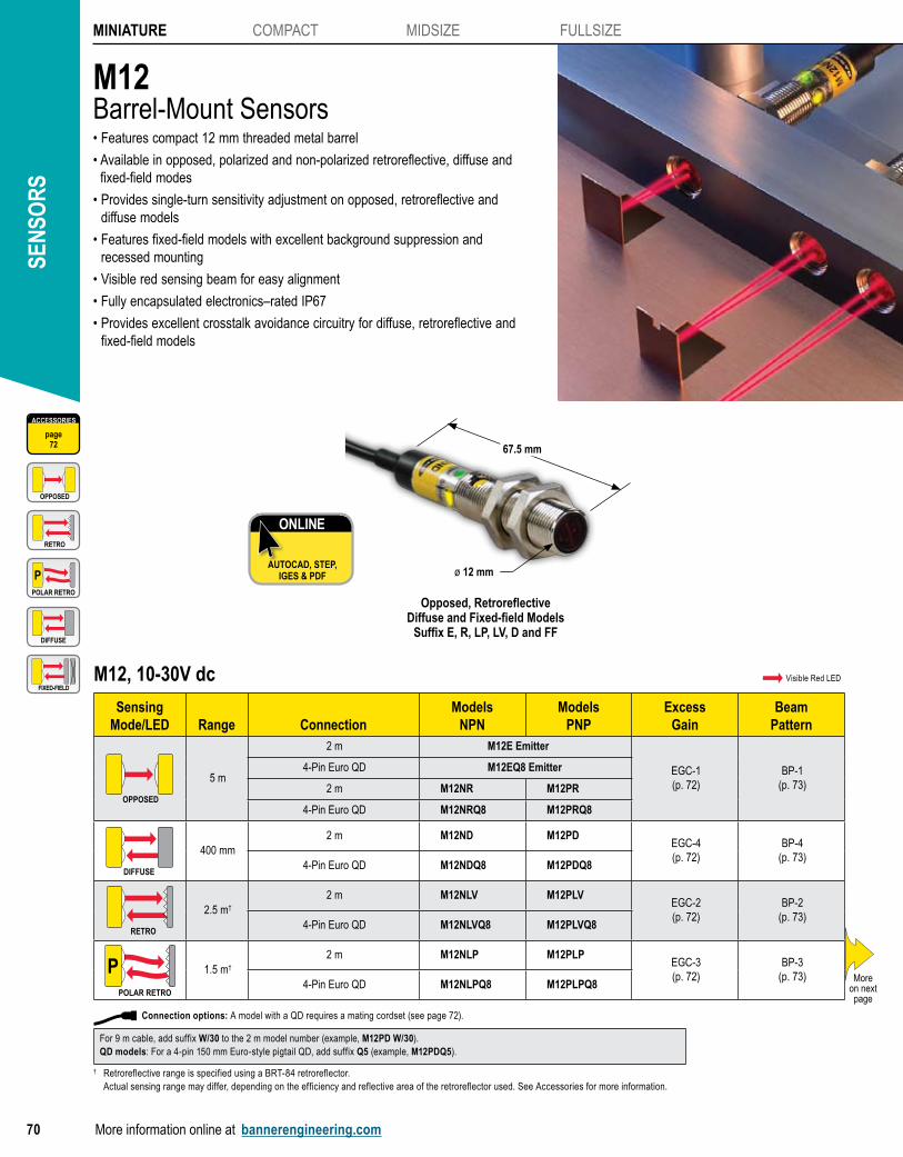
M12Barrel-Mount Sensors• Features compact 12 mm threaded metal barrel
• Available in opposed, polarized and non-polarized retroreflective, diffuse and fixed-field modes
• Provides single-turn sensitivity adjustment on opposed, retroreflective and diffuse models
• Features fixed-field models with excellent background suppression and recessed mounting
• Visible red sensing beam for easy alignment
• Fully encapsulated electronics–rated IP67
• Provides excellent crosstalk avoidance circuitry for diffuse, retroreflective and fixed-field models
M12, 10-30V dc Visible Red LED
Sensing Mode/LED Range Connection
ModelsNPN
ModelsPNP
ExcessGain
BeamPattern
OPPOSED
5 m
2 m M12E Emitter
EGC-1(p. 72)
BP-1(p. 73)
4-Pin Euro QD M12EQ8 Emitter
2 m M12NR M12PR
4-Pin Euro QD M12NRQ8 M12PRQ8
DIFFUSE
400 mm2 m M12ND M12PD
EGC-4(p. 72)
BP-4(p. 73)
4-Pin Euro QD M12NDQ8 M12PDQ8
RETRO
2.5 m†
2 m M12NLV M12PLVEGC-2(p. 72)
BP-2(p. 73)
4-Pin Euro QD M12NLVQ8 M12PLVQ8
POLAR RETRO
P 1.5 m†
2 m M12NLP M12PLPEGC-3(p. 72)
BP-3(p. 73)
4-Pin Euro QD M12NLPQ8 M12PLPQ8
Connection options: A model with a QD requires a mating cordset (see page 72).
For 9 m cable, add suffix W/30 to the 2 m model number (example, M12PD W/30). QD models: For a 4-pin 150 mm Euro-style pigtail QD, add suffix Q5 (example, M12PDQ5).
† Retroreflective range is specified using a BRT-84 retroreflector. Actual sensing range may differ, depending on the efficiency and reflective area of the retroreflector used. See Accessories for more information.
ONLINE
AUTOCAD, STEP, IGES & PDF
Moreon next page
ACCESSORIES
page72
OPPOSED
RETRO
POLAR RETRO
P
DIFFUSE
FIXED-FIELD
Opposed, Retroreflective Diffuse and Fixed-field Models
Suffix E, R, LP, LV, D and FF
67.5 mm
ø 12 mm
MINIATURE
WORLD-BEAM Q12
M12
T8
S12/SB12
VS2
VS3
COMPACT
MIDSIZE
FULLSIZE
More information online at bannerengineering.com 71
PhotoelectricsSensors
Fiber OpticSensors
Special PurposeSensors
Measurement & Inspection Sensors
Vision
Wireless
Indicators
Safety Light Screens
Safety Laser Scanners
Fiber OpticSafety Systems
Safety Controllers & Modules
Safety Two-Hand Control Modules
Safety Interlock Switches
Emergency Stop Devices
M12, 10-30V dc Visible Red LED
Sensing Mode/LED Range Connection
ModelsNPN
ModelsPNP
ExcessGain
BeamPattern
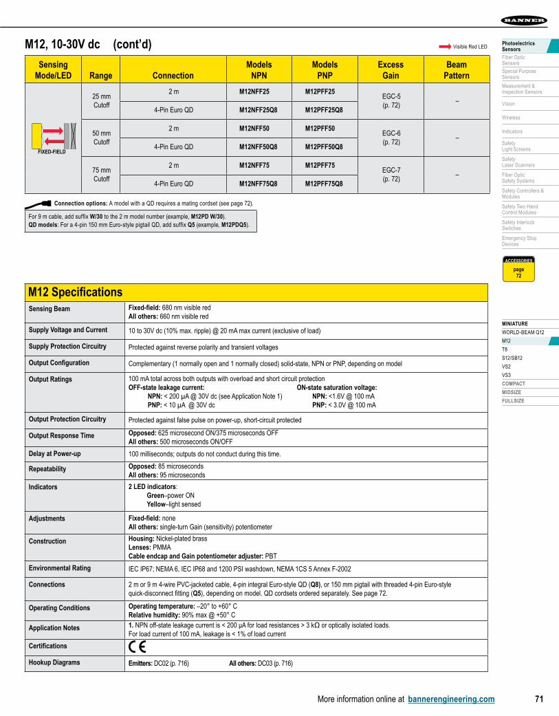
FIXED-FIELDFIXED-FIELD
25 mmCutoff
2 m M12NFF25 M12PFF25EGC-5(p. 72)
–4-Pin Euro QD M12NFF25Q8 M12PFF25Q8
50 mmCutoff
2 m M12NFF50 M12PFF50EGC-6(p. 72)
–4-Pin Euro QD M12NFF50Q8 M12PFF50Q8
75 mmCutoff
2 m M12NFF75 M12PFF75EGC-7(p. 72)
–4-Pin Euro QD M12NFF75Q8 M12PFF75Q8
(cont’d)
M12 SpecificationsSensing Beam Fixed-field: 680 nm visible red
All others: 660 nm visible red
Supply Voltage and Current 10 to 30V dc (10% max. ripple) @ 20 mA max current (exclusive of load)
Supply Protection Circuitry Protected against reverse polarity and transient voltages
Output Configuration Complementary (1 normally open and 1 normally closed) solid-state, NPN or PNP, depending on model
Output Ratings 100 mA total across both outputs with overload and short circuit protection OFF-state leakage current: ON-state saturation voltage: NPN: < 200 µA @ 30V dc (see Application Note 1) NPN: <1.6V @ 100 mA PNP: < 10 µA @ 30V dc PNP: < 3.0V @ 100 mA
Output Protection Circuitry Protected against false pulse on power-up, short-circuit protected
Output Response Time Opposed: 625 microsecond ON/375 microseconds OFF All others: 500 microseconds ON/OFF
Delay at Power-up 100 milliseconds; outputs do not conduct during this time.
Repeatability Opposed: 85 microseconds All others: 95 microseconds
Indicators 2 LED indicators: Green–power ON Yellow–light sensed
Adjustments Fixed-field: none All others: single-turn Gain (sensitivity) potentiometer
Construction Housing: Nickel-plated brass Lenses: PMMA Cable endcap and Gain potentiometer adjuster: PBT
Environmental Rating IEC IP67; NEMA 6, IEC IP68 and 1200 PSI washdown, NEMA 1CS 5 Annex F-2002
Connections 2 m or 9 m 4-wire PVC-jacketed cable, 4-pin integral Euro-style QD (Q8), or 150 mm pigtail with threaded 4-pin Euro-style quick-disconnect fitting (Q5), depending on model. QD cordsets ordered separately. See page 72.
Operating Conditions Operating temperature: –20° to +60° C Relative humidity: 90% max @ +50° C
Application Notes 1. NPN off-state leakage current is < 200 μA for load resistances > 3 kΩ or optically isolated loads.For load current of 100 mA, leakage is < 1% of load current
Certifications
Hookup Diagrams Emitters: DC02 (p. 716) All others: DC03 (p. 716)
ACCESSORIES
page72
For 9 m cable, add suffix W/30 to the 2 m model number (example, M12PD W/30). QD models: For a 4-pin 150 mm Euro-style pigtail QD, add suffix Q5 (example, M12PDQ5).
Connection options: A model with a QD requires a mating cordset (see page 72).

SEN
SOR
SMINIATURE COMPACT MIDSIZE FULLSIZE
72 More information online at bannerengineering.com
Retroreflective ModeM12
M12Retroreflective
DISTANCE
1000
10
100
0.1 m(0.3')
1 m(3.3')
10 m(33')
0.01 m(0.03')
1
EXCESS
GAIN
with BRT-84 reflector
Range: 2.5 m LED:
Opposed ModeM12
M12Opposed
DISTANCE
1000
10000
10
100
0.1 m(0.3')
1.0 m(3.0')
10.0 m(30.0')
0.01 m(.03')
1
EXCESS
GAIN
Range: 5 m LED:
EGC-1 EGC-2
= Visible Red LED P = Visible Red LED Polarized
Excess Gain Curves (Diffuse and Fixed-field mode performance based on 90% reflectance white test card)
Fixed-Field ModeM12
M12Fixed Field - 25 mm
DISTANCE
1000
10
100
10 mm(0.4")
100 mm(4.0")
1000 mm(40.0")
1 mm(.04")
1
EXCESS
GAIN
90% white test card:Ø 2 mm spot size @ 25 mm focusØ 2 mm spot size @ 25 mm cutoff
Using 18% gray test card: cutoffdistance will be 96% of value shown.Using 6% black test card: cutoffdistance will be 94% of value shown.
Cutoff: 25 mm LED:
Fixed-Field ModeM12
M12Fixed Field - 75 mm
DISTANCE
1000
10
100
10 mm(0.4")
100 mm(4.0")
1000 mm(40.0")
1 mm(.04")
1
EXCESS
GAIN
90% white test card:Ø 2 mm spot size @ 25 mm focusØ 13 mm spot size @ 75 mm cutoff
Using 18% gray test card: cutoffdistance will be 80% of value shown.Using 6% black test card: cutoffdistance will be 70% of value shown.
Cutoff: 75 mm LED:
Diffuse ModeM12
M12Diffuse
DISTANCE
1000
10
100
10 mm(0.4")
100 mm(4.0")
1000 mm(40.0")
1 mm(.04")
1
EXCESS
GAIN
Range: 400 mm LED:
PolarizedRetroreflective Mode
M12
with BRT-84 reflector
M12Polarized Retro
DISTANCE
1000
10
100
0.1 m(0.3')
1 m(3.3')
10 m(33')
0.01 m(0.03')
1
EXCESS
GAIN
Range: 1.5 m LED: P
EGC-3 EGC-4
EGC-5
EGC-7
Fixed-Field ModeM12
M12Fixed Field - 50 mm
DISTANCE
1000
10
100
10 mm(0.4")
100 mm(4.0")
1000 mm(40.0")
1 mm(.04")
1
EXCESS
GAIN
90% white test card:Ø 2 mm spot size @ 25 mm focusØ 7 mm spot size @ 50 mm cutoff
Using 18% gray test card: cutoff distance will be 90% of value shown.Using 6% black test card: cutoffdistance will be 85% of value shown.
Cutoff: 50 mm LED:
EGC-6
Euro QDSee page 658
Length
Threaded 4-Pin
Straight Right-Angle
2 m MQDC-406 MQDC-406RA
5 m MQDC-415 MQDC-415RA
9 m MQDC-430 MQDC-430RA
Cordsets BracketsM12
SMBQS12PD
pg. 647
Additional cordset information available.See page 655.
Additional bracket information available.See page 601.
REFLECTORS
PAGE 684
REFLECTORS

MINIATURE
WORLD-BEAM Q12
M12
T8
S12/SB12
VS2
VS3
COMPACT
MIDSIZE
FULLSIZE
More information online at bannerengineering.com 73
PhotoelectricsSensors
Fiber OpticSensors
Special PurposeSensors
Measurement & Inspection Sensors
Vision
Wireless
Indicators
Safety Light Screens
Safety Laser Scanners
Fiber OpticSafety Systems
Safety Controllers & Modules
Safety Two-Hand Control Modules
Safety Interlock Switches
Emergency Stop Devices
Retroreflective ModeM12
(1.6")
(1.6")
(0.8")
(0.8")
(2.4")
(2.4")
(3.1")
(3.1")
2.5 m(8.2')
2 m(6.6')
1.5 m(4.9')
1 m(3.3')
0.5 m(1.6')
0
-20 mm
-40 mm
-60 mm
-80 mm
20 mm
40 mm
60 mm
80 mm
DISTANCE
Beam
Widt
h
M12 Retroreflectivewith BRT-84 reflector 00
Range: 2.5 m LED:
Opposed ModeM12
Effective Beam: 10 mm
(16")
(16")
(8")
(8")
(24")
(24")
5 m(16')
4 m(13')
3 m(9.8')
2 m(6.6')
1 m(3.3')
0
-200 mm
-400 mm
-600 mm
200 mm
400 mm
600 mm
DISTANCE
Beam
Wid
th
M12Opposed
00
Range: 5 m LED:
BP-1 BP-2
= Visible Red LED P = Visible Red LED Polarized
Beam Patterns (Diffuse mode performance based on 90% reflectance white test card)
Diffuse ModeM12
(0.4")
(0.4")
(0.2")
(0.2")
(0.6")
(0.6")
500 mm(20")
400 mm(16")
300 mm(12")
200 mm(8")
100 mm(4")
0
-5 mm
-10 mm
-15 mm
5 mm
10 mm
15 mm
DISTANCE
Beam
Wid
th
M12Diffuse
00
Range: 400 mm LED:
Retroreflective Mode M12
(0.8")
(0.8")
(0.4")
(0.4")
(1.2")
(1.2")
(1.6")
(1.6")
2.0 m(6.5')
1.6 m(5.2')
1.2 m(3.9')
0.8 m(2.6')
0.4 m(1.3')
0
-10 mm
-20 mm
-30 mm
-30 mm
10 mm
20 mm
30 mm
40 mm
DISTANCE
Beam
Widt
h
00M12 Polarized Retrowith BRT-84 reflector
Range: 1.5 m LED: P
BP-3 BP-4

SEN
SOR
SMINIATURE COMPACT MIDSIZE FULLSIZE
74 More information online at bannerengineering.com
T8Right-Angle Barrel-Mount Sensors• Features EZ-BEAM® technology, with specially designed optics and electronics
for reliable sensing without adjustments
• Ideal for presence sensing in small areas previously accessible only to remote sensors and fiber optic cable
• Can replace range-limited 8 mm inductive proximity sensors
• Offers visible sensing beam for easy alignment
• Available in dark- or light-operate models
• Offered in opposed mode with 2 m range or diffuse mode with 50 and 100 mm ranges
T8, 10-30V dc Visible Red LED
Sensing Mode/LED Range Connection
OutputType
ModelsNPN
ModelsPNP
ExcessGain
BeamPattern
OPPOSED
2 m
2 m—
T86EV Emitter
EGC-1(p. 76)
BP-1(p. 76)
3-Pin Pico Pigtail QD T86EVQ Emitter
2 mLO
T8AN6R T8AP6R
3-Pin Pico Pigtail QD T8AN6RQ T8AP6RQ
2 mDO
T8RN6R T8RP6R
3-Pin Pico Pigtail QD T8RN6RQ T8RP6RQ
Connection options: A model with a QD requires a mating cordset (see pages 76).
For 9 m cable, add suffix W/30 to the 2 m model number (example, T8AN6D50 W/30).
ONLINE
AUTOCAD, STEP, IGES & PDF
Moreon next page
ACCESSORIES
page76
OPPOSED
DIFFUSE
Opposed and Diffuse ModelsSuffix E, R and D
ø 16.3 mm
19.1 mm
8.8 mm
ø 8 mm
15.8 mm

MINIATURE
WORLD-BEAM Q12
M12
T8
S12/SB12
VS2
VS3
COMPACT
MIDSIZE
FULLSIZE
More information online at bannerengineering.com 75
PhotoelectricsSensors
Fiber OpticSensors
Special PurposeSensors
Measurement & Inspection Sensors
Vision
Wireless
Indicators
Safety Light Screens
Safety Laser Scanners
Fiber OpticSafety Systems
Safety Controllers & Modules
Safety Two-Hand Control Modules
Safety Interlock Switches
Emergency Stop Devices
T8 SpecificationsSupply Voltage and Current 10 to 30V dc (10% max. ripple) at less than 25 mA (exclusive of load)
Supply Protection Circuitry Protected against reverse polarity and transient voltages
Output Configuration Solid-state switchNPN (current sinking) or PNP (current sourcing), depending on model.Light Operate (LO) or Dark Operate (DO), depending on model.
Output Rating 50 mA max.OFF-state leakage current: less than 1 µA at 24V dcON-state saturation voltage: less than 0.25V at 10 mA dc; less than 0.5V at 50 mA dc
Output Protection Circuitry Protected against false pulse on power-up and continuous overload or short circuit of outputsOverload trip point ≥ 100 mA
Output Response Time 1 millisecond ON; 0.5 milliseconds OFF
Delay at Power-up Maximum 100 milliseconds (150 milliseconds for Diffuse); output does not conduct during this time.
Repeatability Opposed: 100 microsecondsDiffuse: 160 microseconds
Indicators Opposed: Receiver has Green and Red LED Emitter has one Green LED Green: power ON Red: light sensed
Diffuse: Red: light is sensed
Construction Reinforced polycarbonate/ABS alloy housing, acrylic window with 8 mm ABS nut
Environmental Rating IEC IP67; NEMA 6
Connections 2 m or 9 m attached cable, 3-wire with PVC outer cable jacket; or 150 mm pigtail with 3-pin Pico-style quick-disconnect fitting. QD cordsets are ordered separately. See page 76.
Operating Conditions Temperature: -20° to +55° C Relative humidity: 80% at 50° C (non-condensing)
Vibration and Mechanical Shock
Vibration: All models meet IEC 60068-2-6, IEC 60947-5-2, UL491 Section 40, MIL-STD-202F Method 201A;10 to 60 Hz, 0.5 mm peak to peakShock: All models meet IEC 60068-2-27, IEC 60947-5-2; 30g peak acceleration, 11 millisecond pulse duration,half-sine wave pulse shape
Certifications
Hookup Diagrams Emitters: DC02 (p. 716) All others: DC01 (p. 716)
T8, 10-30V dc Visible Red LED
Sensing Mode/LED Range Connection
OutputType
ModelsNPN
ModelsPNP
ExcessGain
BeamPattern
DIFFUSE
50 mm
2 mLO
T8AN6D50 T8AP6D50
EGC-2(p. 76)
BP-2(p. 76)
3-Pin Pico Pigtail QD T8AN6D50Q T8AP6D50Q
2 mDO
T8RN6D50 T8RP6D50
3-Pin Pico Pigtail QD T8RN6D50Q T8RP6D50Q
100 mm
2 mLO
T8AN6D100 T8AP6D100
EGC-3(p. 76)
BP-3(p. 76)
3-Pin Pico Pigtail QD T8AN6D100Q T8AP6D100Q
2 mDO
T8RN6D100 T8RP6D100
3-Pin Pico Pigtail QD T8RN6D100Q T8RP6D100Q
(cont’d)
ACCESSORIES
page76
Connection options: A model with a QD requires a mating cordset (see pages 76).
For 9 m cable, add suffix W/30 to the 2 m model number (example, T8AN6D50 W/30).

SEN
SOR
SMINIATURE COMPACT MIDSIZE FULLSIZE
76 More information online at bannerengineering.com
Pico QDSee page 655
Length
Threaded 3-Pin
Straight Right-Angle
2 m PKG3M-2 PKW3M-2
5 m PKG3M-5 —
7 m PKG3M-7 —
9 m PKG3M-9 PKW3M-9
10 m PKG3M-10 —
Cordsets BracketsT8
SMB8MM
pg. 625
Diffuse ModeT8
1
10
100
10 mm(0.4")
100 mm(4")
1000 mm(40")
1.0 mm(0.04")
1000
EXCESS
GAIN
DISTANCE
T8xx6D50
Diffuse Mode
Range: 50 m LED:
Opposed ModeT8
1
10
100
0.1 m(0.32')
1 m(3.2')
10 m(32')
0.01(0.032')
1000
EXCESS
GAIN
DISTANCE
T8E&R
Opposed Mode
Range: 2 m LED:
EGC-1 EGC-2
= Visible Red LED
Excess Gain Curves (Diffuse mode performance based on 90% reflectance white test card)
Diffuse ModeT8
1
10
100
10 mm(0.4")
100 mm(4")
1000 mm(40")
1.0 mm(0.04")
1000
EXCESS
GAIN
DISTANCE
T8xx6D100
Diffuse Mode
Range: 100 mm LED:
EGC-3
Diffuse ModeT8
100 mm(4.0")
80 mm(3.2")
60 mm(2.4")
40 mm(1.6")
20 mm(0.8")
0
0
20 mm
40 mm
60 mm
20 mm
40 mm
60 mm
0
0.8"
1.6"
2.4"
0.8"
1.6"
2.4"
DISTANCE
T8xx6D50Diffuse Mode
Range: 50 mm LED:
Opposed ModeT8
Effective Beam: 4.3 mm
2.0 m(6.5')
1.6 m(5.2')
1.2 m(3.9')
0.8 m(2.6')
0.4 m(1.3')
0
0
20.0 mm
40.0 mm
60.0 mm
20.0 mm
40.0 mm
60.0 mm
0
0.75"
1.50"
2.25"
0.75"
1.50"
2.25"
DISTANCE
T8E&ROpposed Mode
Range: 2 m LED:
BP-1 BP-2
= Visible Red LED
Beam Patterns (Diffuse mode performance based on 90% reflectance white test card)
Diffuse ModeT8
100 mm(4.0")
80 mm(3.2")
60 mm(2.4")
40 mm(1.6")
20 mm(0.8")
0
0
20 mm
40 mm
60 mm
20 mm
40 mm
60 mm
0
0.8"
1.6"
2.4"
0.8"
1.6"
2.4"
DISTANCE
Diffuse ModeT8xx6D100
Range: 100 mm LED:
BP-3
Additional cordset information available.See page 655.
Additional bracket information available.See page 601.

MINIATURE
WORLD-BEAM Q12
M12
T8
S12/SB12
VS2
VS3
COMPACT
MIDSIZE
FULLSIZE
More information online at bannerengineering.com 77
PhotoelectricsSensors
Fiber OpticSensors
Special PurposeSensors
Measurement & Inspection Sensors
Vision
Wireless
Indicators
Safety Light Screens
Safety Laser Scanners
Fiber OpticSafety Systems
Safety Controllers & Modules
Safety Two-Hand Control Modules
Safety Interlock Switches
Emergency Stop Devices
S12 & SB12Opposed-Mode Barrel-Mount Sensors• S12 threaded housing for heavy-duty industrial sensing
- Rugged IP67-rated housinig - Reliable sensing up to 15 m
• Economical, SB12/SB12T sensors for people detection applications in escalators, turnstiles and ticket booths - SB12 snap-barrel housing for applications where mounting holes are precisely
located and formed, and sensor can be hidden behind a protective window
- SB12T threaded housing for robust mounting in applications with vibration, rough handling or vandalism
- Narrow beam for reliable operation of multiple sensors in close proximity
- Reliable short-range detection up to 1.5 m
ø 15.8 mmø 15.8 mm
SB12TOpposed Models
SB12Opposed Models
S12Opposed Models
30.5 mm
S12, 10-30V dc Visible Red LED
Sensing Mode/LED Range Connection
ModelsNPN
ModelsPNP
ExcessGain
BeamPattern
OPPOSED
15 m2 m S126E
EGC-1(p. 79)
BP-1(p. 79)
2 m S12SN6R S12SP6R
SB12, 10-30V dc Infrared Red LED
Sensing Mode/LED Range Connection Output
ModelsNPN
ModelsPNP
ExcessGain
BeamPattern
OPPOSEDOPPOSED
1.5 m 2 m
_ SB12E1
—BP-2
(p. 79)LO SB12ANR SB12APR
DO SB12RNR SB12RPR
ONLINE
AUTOCAD, STEP, IGES & PDF
31 mm 59.9 mm
ACCESSORIES
page79
OPPOSED
ø 12 mm
QD models: For a 3-pin 150 mm Pico-style pigtail QD, add suffix Q3 (example, SB12E1Q3).
Connection options: A model with a QD requires a mating cordset (see page 79).
QD models: For a 4-pin 150 mm Pico-style pigtail QD, add suffix QP (example, S12SN6RQP).
Connection options: A model with a QD requires a mating cordset (see page 79).
ø 12 mm

SEN
SOR
SMINIATURE COMPACT MIDSIZE FULLSIZE
78 More information online at bannerengineering.com
SB12T, 10-30V dc Infrared Red LED
Sensing Mode/LED Range Connection Output
ModelsNPN
ModelsPNP
ExcessGain
BeamPattern
OPPOSEDOPPOSED
1.5 m 2 m
_ SB12TE1
—BP-2
(p. 79)LO SB12TANR SB12TAPR
DO SB12TRNR SB12TRPR
ACCESSORIES
page79
S12/SB12 SpecificationsSupply Voltage and Current S12: 10 to 30V dc (10% max. ripple); 25 mA (emitters) or 20 mA (receivers) exclusive of load
SB12/SB12T: 10 to 30V dc; less than 15 mA max exclusive of load
Supply Protection Circuitry Protected against reverse polarity and transient voltages
Output Configuration SB12/SB12T: One solid state output, NPN (sinking) or PNP (sourcing), depending on modelS12: Complementary solid-state dc switch; choose NPN (current sinking) or PNP (current sourcing) models Light operate: N.O. output conducts when the sensor sees the emitter’s modulated light Dark operate: N.C. output conducts when the sensor sees dark; The N.C. (normally closed) output may be wired as a normally open marginal signal alarm output, depending upon hookup to the power supply
Output Ratings S12:100 mA maximum (each) in standard hookup; when wired for alarm output, the total load may not exceed 100 mAOFF-state leakage current: less than 1 μA @ 30V dcON-state saturation voltage: less than 1V @ 10 mA; less than 1.5V @ 150 mA
SB12/SB12T:100 mAOFF-state leakage current: < 10 μAON-state saturation voltage: < 0.2V @ 10 mA; < 0.6V @ 100 mA
Output Protection Circuitry Protected against false pulse on power-up and continuous overload or short circuit of outputs
Output Response Time S12: 3 milliseconds ON, 1.5 milliseconds OFFSB12/SB12T: 2.5 milliseconds ON, 1.75 milliseconds OFF
Delay at Power-up S12: 100 millisecond; outputs are non-conducting during this time.SB12/SB12T: Less than 1 second delay on power-up.
Repeatability S12: 375 microsecondsSB12/SB12T: 350 microseconds
Switching Frequency SB12/SB12T: 235 Hz
Indicators Green LED (emitter and receiver): power ONAmber LED (receiver only): light sensed
Construction S12: Housings are reinforced thermoplastic polyester; lenses are Lexan®; Polyurethane end capSB12/SB12T: Housing: ABS Lens: Polycarbonate; epoxy encapsulant Cable: PVC-jacketed
Environmental Rating S12: Leakproof design rated NEMA 6P (IEC IP67)SB12: IP65 SB12T: IP67
Connections S12: 2 m or 9 m cable, or a 150 mm pigtail with 4-pin Pico-style QDSB12/SB12T: 2 m cable or 150 mm pigtail with 3-pin Pico-style QDQD cordset ordered separately. See page 79.
Operating Conditions S12: Temperature: -40º to +70º C Maximum relative humidity: 90% at 50°C (non-condensing)SB12/SB12T: Temperature: -20º to +50º C
Vibration andMechanical Shock
S12: Meets Mil. Std. 202F requirements. Method 201A (Vibration: frequency 10 to 60 Hz, max., double amplitude 0.06-inch acceleration 10G). Method 213B conditions H&I (Shock: 75G with unit operating; 100G for non-operation).
Certifications
Hookup Diagrams Emitters: DC02 (p. 716) S12 Receivers NPN: DC05 (p. 717) S12 Receivers PNP: DC06 (p. 717) SB12/SB12T Receivers: DC01 (p. 716)
Lexan® is a registered trademark of General Electric Co.
QD models: For a 3-pin 150 mm Pico-style pigtail QD, add suffix Q3 (example, SB12TE1Q3).
Connection options: A model with a QD requires a mating cordset (see page 79).

MINIATURE
WORLD-BEAM Q12
M12
T8
S12/SB12
VS2
VS3
COMPACT
MIDSIZE
FULLSIZE
More information online at bannerengineering.com 79
PhotoelectricsSensors
Fiber OpticSensors
Special PurposeSensors
Measurement & Inspection Sensors
Vision
Wireless
Indicators
Safety Light Screens
Safety Laser Scanners
Fiber OpticSafety Systems
Safety Controllers & Modules
Safety Two-Hand Control Modules
Safety Interlock Switches
Emergency Stop Devices
Opposed ModeSB12/SB12T
DISTANCE
SB12Opposed Mode
1.2 m48"
1.6 m64"
2.0 m80"
0.8 m32"
0.4 m16"
0
0
50 mm
100 mm
150 mm
50 mm
100 mm
150 mm
0
2"
4"
6"
2"
4"
6"
Range: 1.5 m LED:
Opposed ModeS12
25 m82'
20 m66'
15 m49'
10 m32'
5 m16'
0
0
500 mm
1000 mm
1500 mm
500 mm
1000 mm
1500 mm
0
20''
40''
60''
20''
40''
60''
DISTANCE
S12 SeriesOpposed Mode
Range: 15 m LED:
BP-1 BP-2
= Visible Red LED = Infrared LED
Beam Patterns
Opposed ModeS12
1
10
100
1 m3.3'
10 m33'
100 m330'
.1 m.33'
egc s12 series opp.eps
1000
EXCESS
GAIN
DISTANCE
S12 Series
Opposed Mode
Range: 15 m LED:
EGC-1
= Visible Red LED
Excess Gain Curves
BracketsS12
SMB12MM
pg. 616
Pico QDSee page 655
Length
Threaded 3-Pin
Straight Right-Angle
2 m PKG3M-2 PKW3M-2
5 m PKG3M-5 PKW3M-5
7 m PKG3M-7 —
9 m PKG3M-9 PKW3M-9
10 m PKG3M-10 —
Cordsets Pico QD
See page 657
Length
Snap-on 4-Pin
Straight Right-Angle
2 m PKG4-2 PKW4Z-2
Additional cordset information available.See page 655.
Additional bracket information available.See page 601.
Effective Beam: 8.1 mm Effective Beam: 8.3 mm

SEN
SOR
SMINIATURE COMPACT MIDSIZE FULLSIZE
80 More information online at bannerengineering.com
VS2Ultra-Thin Miniature Sensors• Features EZ-BEAM® technology, with specially designed optics and electronics
for reliable sensing without adjustments
• Available in opposed and convergent modes
• Ideal as a low-cost, high-quality miniaturized solution for confined areas
• Available in dark- or light-operate models
• Offers flat front mounting or optional bracket
4.7 mm
12.0 mm
25.1 mm
Convergent ModelsSuffix C
ONLINE
AUTOCAD, STEP, IGES & PDF
VS2, 10-30V dc
Sensing Mode/LED Range Connection
OutputType
Models†
NPNModels†
PNPExcess
GainBeam
Pattern
OPPOSED
Optimum up to 600 mm,1.2 m max.
2 m —
VS25EV Emitter
EGC-1(p. 82)
BP-1(p. 82)
3-Pin Pico Pigtail QD VS25EVQ Emitter
2 mLO
VS2AN5R VS2AP5R
3-Pin Pico Pigtail QD VS2AN5RQ VS2AP5RQ
2 mDO
VS2RN5R VS2RP5R
3-Pin Pico Pigtail QD VS2RN5RQ VS2RP5RQ
OPPOSEDOPPOSED
3.0 m
2 m—
VS25E Emitter
EGC-2(p. 82)
BP-2(p. 82)
3-Pin Pico Pigtail QD VS25EQ Emitter
2 mLO
VS2AN5R VS2AP5R
3-Pin Pico Pigtail QD VS2AN5RQ VS2AP5RQ
2 mDO
VS2RN5R VS2RP5R
3-Pin Pico Pigtail QD VS2RN5RQ VS2RP5RQ
Moreon next page
Visible Red LED Infrared LED
ACCESSORIES
page82
OPPOSED
CONVERGENT
Opposed ModelsSuffix E and R
4.3 mm
25.1 mm
12.0 mm
8.0 mm
For 9 m cable, add suffix W/30 to the 2 m model number (example, VS2RP5R W/30).
† Opposed-mode models also sold as pairs. Contact factory for more information 1-888-373-6767.
Connection options: A model with a QD requires a mating cordset (see page 82).

MINIATURE
WORLD-BEAM Q12
T8
M12
S12/SB12
VS2
VS3
COMPACT
MIDSIZE
FULLSIZE
More information online at bannerengineering.com 81
PhotoelectricsSensors
Fiber OpticSensors
Special PurposeSensors
Measurement & Inspection Sensors
Vision
Wireless
Indicators
Safety Light Screens
Safety Laser Scanners
Fiber OpticSafety Systems
Safety Controllers & Modules
Safety Two-Hand Control Modules
Safety Interlock Switches
Emergency Stop Devices
VS2, 10-30V dc
Sensing Mode/LED Range Connection
OutputType
Models†
NPNModels†
PNPExcess
GainBeam
Pattern
CONVERGENT
15 mm±5 mm
2 mLO
VS2AN5CV15 VS2AP5CV15
EGC-3(p. 82)
BP-3(p. 82)
3-Pin Pico Pigtail QD VS2AN5CV15Q VS2AP5CV15Q
2 mDO
VS2RN5CV15 VS2RP5CV15
3-Pin Pico Pigtail QD VS2RN5CV15Q VS2RP5CV15Q
30 mm±10 mm
2 mLO
VS2AN5CV30 VS2AP5CV30
EGC-4(p. 82)
BP-4(p. 82)
3-Pin Pico Pigtail QD VS2AN5CV30Q VS2AP5CV30Q
2 mDO
VS2RN5CV30 VS2RP5CV30
3-Pin Pico Pigtail QD VS2RN5CV30Q VS2RP5CV30Q
VS2 SpecificationsSupply Voltage and Current 10 to 30V dc (10% max. ripple) at less than 25 mA (exclusive of load)
Supply Protection Circuitry Protected against reverse polarity and transient voltages
Output Configuration Solid-state switchNPN (current sinking) or PNP (current sourcing), depending on modelLight Operate (LO) or Dark Operate (DO), depending on model
Output Rating 50 mA max.OFF-state leakage current: less than 1 µA at 24V dcON-state saturation voltage: less than 0.25V at 10 mA dc; less than 0.5V at 50 mA dc
Output Protection Circuitry Protected against false pulse on power-up and continuous overload or short circuit of outputsOverload trip point ≥ 100 mA
Output Response Time Opposed: 1 millisecond ON; 0.5 millisecond OFFConvergent: 1 millisecond ON; OFF
Delay at Power-up Maximum 100 millisecond (opposed) and 150 millisecond (convergent); output does not conduct during this time.
Repeatability Opposed: 100 microseconds Convergent: 160 microseconds
Indicators Two LEDs: Green: power ON Yellow: light sensed
Construction Opposed: Black ABS housing with clear MABS lensConvergent: Black ABS housing with acrylic lens
Environmental Rating IEC IP67; NEMA 6
Connections 2 m or 9 m attached cable, 3-wire with PVC outer cable jacket; or 150 mm pigtail with 3-pin Pico-style quick-disconnect fitting. QD cordsets are ordered separately. See page 82.
Operating Conditions Temperature: -20° to +55° C Relative humidity: 80% at 50° C (non-condensing)
Vibration and MechanicalShock
Vibration: All models meet IEC 60068-2-6, IEC 60947-5-2, UL491 Section 40, MIL-STD-202F Method 201A; 10 to 60 Hz, 0.5 mm peak to peakShock: All models meet IEC 60068-2-27, IEC 60947-5-2; 30g peak acceleration, 11 millisecond pulse duration, half-sine wave pulse shape
Application Notes M2 stainless steel mounting hardware is included. Optional mounting brackets are available. See page 82.
Certifications
Hookup Diagrams Emitters: DC02 (p. 716) All others: DC01 (p. 716)
(cont’d) Visible Red LED
For 9 m cable, add suffix W/30 to the 2 m model number (example, VS2RP5R W/30).
† Opposed-mode models also sold as pairs. Contact factory for more information 1-888-373-6767.
Connection options: A model with a QD requires a mating cordset (see page 82).
ACCESSORIES
page82
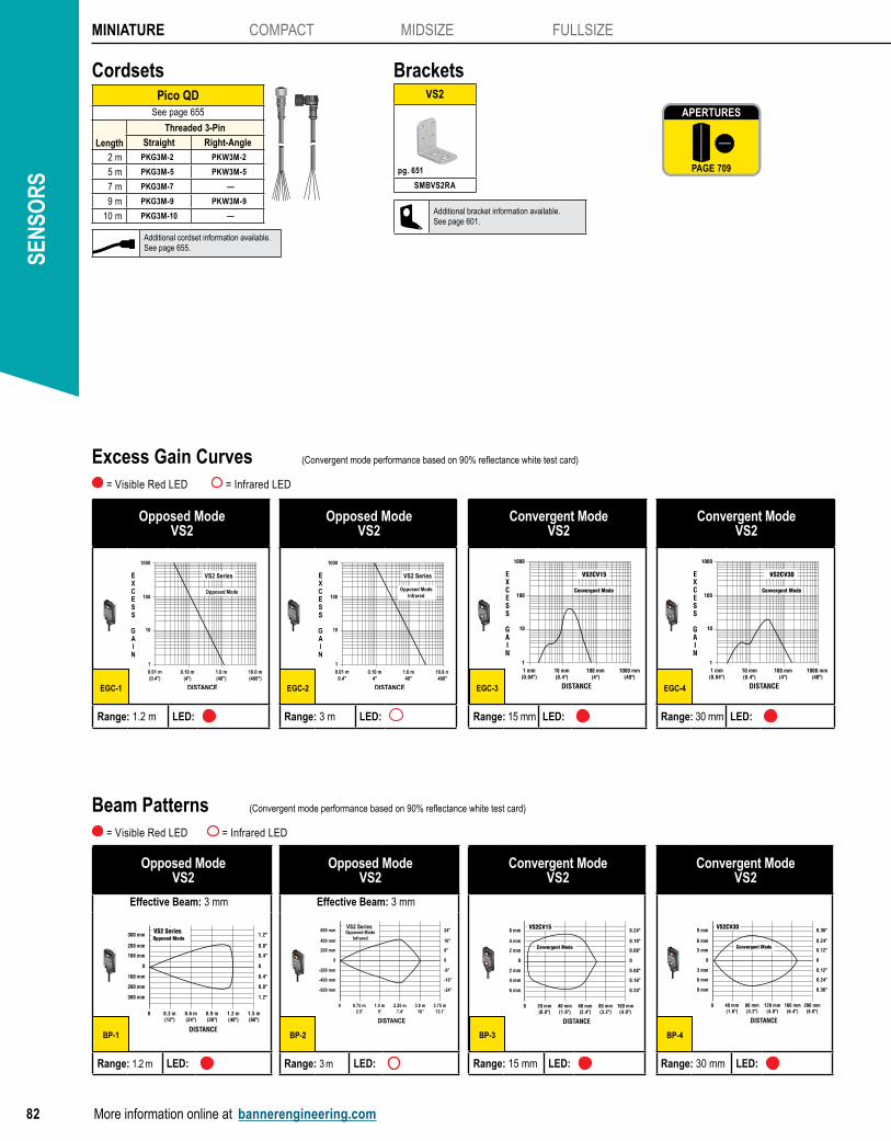
SEN
SOR
SMINIATURE COMPACT MIDSIZE FULLSIZE
82 More information online at bannerengineering.com
BracketsVS2
SMBVS2RA
pg. 651
Pico QDSee page 655
Length
Threaded 3-Pin
Straight Right-Angle
2 m PKG3M-2 PKW3M-2
5 m PKG3M-5 PKW3M-5
7 m PKG3M-7 —
9 m PKG3M-9 PKW3M-9
10 m PKG3M-10 —
Cordsets
Opposed ModeVS2
1
10
100
0.10 m4"
1.0 m40"
10.0 m400"
0.01 m0.4"
EXCESS
GAIN
DISTANCE
1000
VS2 Series
Opposed ModeInfrared
Range: 3 m LED:
Opposed ModeVS2
1
10
100
0.10 m(4")
1.0 m(40")
10.0 m(400")
0.01 m(0.4")
EXCESS
GAIN
DISTANCE
1000
VS2 Series
Opposed Mode
Range: 1.2 m LED:
EGC-1 EGC-2
= Visible Red LED = Infrared LED
Excess Gain Curves (Convergent mode performance based on 90% reflectance white test card)
Convergent ModeVS2
1
10
100
10 mm(0.4")
100 mm(4")
1000 mm(40")
1 mm(0.04")
EXCESS
GAIN
DISTANCE
1000
VS2CV30
Convergent Mode
Range: 30 mm LED:
Convergent ModeVS2
1
10
100
10 mm(0.4")
100 mm(4")
1000 mm(40")
1 mm(0.04")
EXCESS
GAIN
DISTANCE
1000
VS2CV15
Convergent Mode
Range: 15 mm LED:
EGC-3 EGC-4
Opposed ModeVS2
Effective Beam: 3 mm
3.75 m13.1'
3.0 m 10 '
2.25 m7.4'
1.5 m5'
0.75 m2.5'
0
0
-200 mm
-400 mm
-600 mm
200 mm
400 mm
600 mm
0
-8"
-16"
-24"
8"
16"
24"
DISTANCE
VS2 SeriesOpposed Mode
Infrared
Effective Beam: 3 mm
Range: 3 m LED:
Opposed ModeVS2
Effective Beam: 3 mm
1.5 m(60")
1.2 m(48")
0.9 m(36")
0.6 m(24")
0.3 m(12")
0
0
100 mm
200 mm
300 mm
100 mm
200 mm
300 mm
0
0.4"
0.8"
1.2"
0.4"
0.8"
1.2"
DISTANCE
VS2 SeriesOpposed Mode
Range: 1.2 m LED:
BP-1 BP-2
= Visible Red LED = Infrared LED
Beam Patterns (Convergent mode performance based on 90% reflectance white test card)
Convergent ModeVS2
200 mm(8.0")
160 mm(6.4")
120 mm(4.8")
80 mm(3.2")
40 mm(1.6")
0
0
3 mm
6 mm
9 mm
3 mm
6 mm
9 mm
0
0.12"
0.24"
0.36"
0.12"
0.24"
0.36"
DISTANCE
VS2CV30
Convergent Mode
Range: 30 mm LED:
Convergent ModeVS2
100 mm(4.0")
80 mm(3.2")
60 mm(2.4")
40 mm(1.6")
20 mm(0.8")
0
0
2 mm
4 mm
6 mm
2 mm
4 mm
6 mm
0
0.08"
0.16"
0.24"
0.08"
0.16"
0.24"
DISTANCE
VS2CV15
Convergent Mode
Range: 15 mm LED:
BP-3 BP-4
Additional cordset information available.See page 655.
Additional bracket information available.See page 601.
APERTURES
PAGE 709
APERTURES
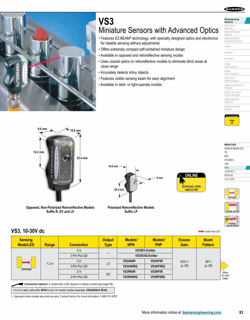
MINIATURE
WORLD-BEAM Q12
T8
M12
S12/SB12
VS2
VS3
COMPACT
MIDSIZE
FULLSIZE
More information online at bannerengineering.com 83
PhotoelectricsSensors
Fiber OpticSensors
Special PurposeSensors
Measurement & Inspection Sensors
Vision
Wireless
Indicators
Safety Light Screens
Safety Laser Scanners
Fiber OpticSafety Systems
Safety Controllers & Modules
Safety Two-Hand Control Modules
Safety Interlock Switches
Emergency Stop Devices
VS3Miniature Sensors with Advanced Optics • Features EZ-BEAM® technology, with specially designed optics and electronics
for reliable sensing without adjustments
• Offers extremely compact self-contained miniature design
• Available in opposed and retroreflective sensing modes
• Uses coaxial optics on retroreflective models to eliminate blind areas at close range
• Accurately detects shiny objects
• Features visible sensing beam for easy alignment
• Available in dark- or light-operate models
16.6 mm
25.4 mm
9 mm
35.2 mm
14.2 mm
7.3 mm
16.6 mm13.6 mm
25.4 mm16.4 mm
9 mm4.5 mm
ø3.2 mm
Polarized Retroreflective ModelsSuffix LP
ONLINE
AUTOCAD, STEP, IGES & PDF
Moreon next page
Opposed, Non-Polarized Retroreflective ModelsSuffix R, EV and LV
25.4 mm
9.0 mm 15.6 mm
14.2 mm
For 9 m cable, add suffix W/30 to the 2 m model number (example, VS3AN5XLV W/30).
† Opposed-mode models also sold as pairs. Contact factory for more information 1-888-373-6767.
Connection options: A model with a QD requires a mating cordset (see page 85).
ACCESSORIES
page85
OPPOSED
COAXIAL RETRO
COAXIALPOLAR RETRO
P
VS3, 10-30V dc Visible Red LED
Sensing Mode/LED Range Connection
OutputType
ModelsNPN
ModelsPNP
ExcessGain
BeamPattern
OPPOSED
1.2 m
2 m—
VS35EV Emitter
EGC-1(p. 85)
BP-1(p. 85)
3-Pin Pico QD VS35EVQ Emitter
2 mLO
VS3AN5R VS3AP5R
3-Pin Pico QD VS3AN5RQ VS3AP5RQ
2 mDO
VS3RN5R VS3RP5R
3-Pin Pico QD VS3RN5RQ VS3RP5RQ
† †

SEN
SOR
SMINIATURE COMPACT MIDSIZE FULLSIZE
84 More information online at bannerengineering.com
ACCESSORIES
page85
VS3, 10-30V dc Visible Red LED
Sensing Mode/LED Range Connection
OutputType
ModelsNPN
ModelsPNP
ExcessGain
BeamPattern
COAXIAL RETRO
250 mm†
2 mLO
VS3AN5XLV VS3AP5XLV
EGC-2(p. 85)
BP-2(p. 85)
3-Pin Pico QD VS3AN5XLVQ VS3AP5XLVQ
2 mDO
VS3RN5XLV VS3RP5XLV
3-Pin Pico QD VS3RN5XLVQ VS3RP5XLVQ
COAXIALPOLAR RETRO
P 250 mm†
2 mLO
VS3AN5XLP VS3AP5XLP
EGC-2(p. 85)
BP-2(p. 85)
3-Pin Pico QD VS3AN5XLPQ VS3AP5XLPQ
2 mDO
VS3RN5XLP VS3RP5XLP
3-Pin Pico QD VS3RN5XLPQ VS3RP5XLPQ
VS3 SpecificationsSupply Voltage and Current 10 to 30V dc (10% max. ripple) at less than 25 mA (exclusive of load)
Supply Protection Circuitry Protected against reverse polarity and transient voltages
Output Configuration Solid-state switchNPN (current sinking) or PNP (current sourcing), depending on modelLight Operate (LO) or Dark Operate (DO), depending on model
Output Protection Circuitry Protected against false pulse on power-up and continuous overload or short circuit of outputs. Overload trip point ≥ 100 mA
Output Rating 50 mA max.OFF-state leakage current: less than 1 µA at 24V dcON-state saturation voltage: less than 0.25V at 10 mA dc; less than 0.5V at 50 mA dc
Output Response Time Opposed: 1 millisecond ON; 0.5 millisecond OFFRetroreflective: 1 millisecond ON/OFF
Delay at Power-up Maximum 100 millisecond (opposed mode) and 150 millisecond (retroreflective); output does not conduct during this time.
Repeatability Opposed: 100 microsecondsRetroreflective: 160 microseconds
Indicators Two LEDs: Green: power ON Yellow: light sensed
Construction Opposed and Non-polarized Retroreflective: Black ABS housing with acrylic lensPolarized Retroreflective: Black ABS housing with glass lens and acrylic cover
Environmental Rating IEC IP67; NEMA 6
Connections 2 m or 9 m attached cable, 3-wire with PVC outer cable jacket; or 3-pin Pico-style quick-disconnect fitting.QD cordsets are ordered separately. See page 85.
Operating Conditions Temperature: -20° to +55° C Relative humidity: 80% at 50° C (non-condensing)
Vibration and Mechanical Shock Vibration: All models meet IEC 60068-2-6, IEC 60947-5-2, UL491 Section 40, MIL-STD-202F Method 201A; 10 to 60 Hz, 0.5 mm peak to peakShock: All models meet IEC 60068-2-27, IEC 60947-5-2; 30g peak acceleration, 11 millisecond pulse duration, half-sine wave pulse shape
Application Notes M3 stainless steel mounting hardware is included. Optional mounting brackets are available. See page 85.
Certifications
Hookup Diagrams Emitters: DC02 (p. 716) All others: DC01 (p. 716)
(cont’d)
For 9 m cable, add suffix W/30 to the 2 m model number (example, VS3AN5XLV W/30).
† Retroflective range is specified using one model BRT-32X20AM retroreflector. Actual sensing range may differ, depending on efficiency and reflective area of the retroreflector in use. See accessories for more information.
Connection options: A model with a QD requires a mating cordset (see page 85).

MINIATURE
WORLD-BEAM Q12
T8
M12
S12/SB12
VS2
VS3
COMPACT
MIDSIZE
FULLSIZE
More information online at bannerengineering.com 85
PhotoelectricsSensors
Fiber OpticSensors
Special PurposeSensors
Measurement & Inspection Sensors
Vision
Wireless
Indicators
Safety Light Screens
Safety Laser Scanners
Fiber OpticSafety Systems
Safety Controllers & Modules
Safety Two-Hand Control Modules
Safety Interlock Switches
Emergency Stop Devices
Retroreflective ModeVS3
1
10
100
10 mm (0.4")
100 mm (4")
1000 mm (40")
1 mm (0.04")
E X C E S S
G A I N
DISTANCE
1000
VS3XLV
Retroreflective Mode
with BRT-32X20AMReflector
Range:250 mm LED:
Opposed ModeVS3
1
10
100
100 mm(4")
1000 mm(40")
10000 mm(400")
10 mm(0.4")
EXCESS
GAIN
DISTANCE
1000
VS3 Series
Opposed Mode
Range: 1.2 m LED:
EGC-1 EGC-2
= Visible Red LED P = Visible Red LED Polarized
Excess Gain Curves
PolarizedRetroreflective Mode
VS3
1
10
100
10 mm (0.4")
100 mm (4")
1000 mm (40")
1 mm (0.04")
E X C E S S
G A I N
DISTANCE
1000
VS3XLP
PolarizedRetroreflective
Mode
with BRT-32X20AMReflector
Range:250 mm LED: P
EGC-3
Retroreflective ModeVS3
250 mm (10.0")
200 mm (8.0")
150 mm (6.0")
100 mm (4.0")
50 mm (2.0")
0
0
5 mm
10 mm
15 mm
5 mm
10 mm
15 mm
0
0.20"
0.40"
0.60"
0.20"
0.40"
0.60"
DISTANCE
VS3XLV
RetroreflectiveMode
with BRT-32X20AMReflector
Range: 250 mm LED:
Opposed ModeVS3
Effective Beam: 3 mm
1500 mm(60.0")
1200 mm(48.0")
900 mm(36.0")
600 mm(24.0")
300 mm(12.0")
0
0
20 mm
40 mm
60 mm
20 mm
40 mm
60 mm
0
0.80"
1.60"
2.40"
0.80"
1.60"
2.40"
DISTANCE
VS3 Series
OpposedMode
Range: 1.2 m LED:
BP-1 BP-2
= Visible Red LED P = Visible Red LED Polarized
Beam Patterns
PolarizedRetroreflective Mode
VS3
250 mm (10.0")
200 mm (8.0")
150 mm (6.0")
100 mm (4.0")
50 mm (2.0")
0
0
5 mm
10 mm
15 mm
5 mm
10 mm
15 mm
0
0.20"
0.40"
0.60"
0.20"
0.40"
0.60"
DISTANCE
VS3XLP
RetroreflectiveMode
with BRT-32X20AMReflector
Range: 250 mm LED: P
BP-3
BracketsVS3
SMBVS3S SMBVS3T
pg. 652 pg. 652
Pico QDSee page 655
Length
Threaded 3-Pin
Straight Right-Angle
2 m PKG3M-2 PKW3M-2
5 m PKG3M-5 PKW3M-5
7 m PKG3M-7 —
9 m PKG3M-9 PKW3M-9
10 m PKG3M-10 —
Cordsets
Additional cordset information available.See page 655.
Additional bracket information available.See page 601.
REFLECTORS
PAGE 684
REFLECTORS