
Banks Ram-Air Intake System
20
05/13/13 PN 96497 v.8.0 Banks Ram-Air ® Intake System 2007-2012 Dodge 6.7L Cummins Pickup Trucks THIS MANUAL IS FOR USE WITH KIT 42175, 42180 Gale Banks Engineering 546 Duggan Avenue • Azusa, CA 91702 (626) 969- 9600 • Fax (626) 334-1743 Product Information & Sales: (888) 635-4565 Customer Support: (888) 839-5600 Installation Support: (888) 839-2700 bankspower.com ©2013 Gale Banks Engineering Owner’sManual with Installation Instructions
Transcript of Banks Ram-Air Intake System

05/13/13 PN 96497 v.8.0
Banks Ram-Air® Intake System 2007-2012 Dodge 6.7L Cummins Pickup Trucks THIS MANUAL IS FOR USE WITH KIT 42175, 42180
Gale Banks Engineering 546 Duggan Avenue • Azusa, CA 91702 (626) 969-9600 • Fax (626) 334-1743
Product Information & Sales: (888) 635-4565Customer Support: (888) 839-5600 Installation Support: (888) 839-2700
bankspower.com
©2013 Gale Banks Engineering
Owner’sManualwith Installation Instructions

2 96497 v.8.0
Products available from Banks Power for the 07-10 Dodge 6.7L
Banks Monster Exhaust SystemSingle (P/N 49764) Duals (P/N 49765)Single Dual Tip (P/N 49766)Duals Quad Tip (P/N 49767)
- Provides increased air flow to the engine by increasing air density for more increased power, lower EGTs and improved fuel economy.
Banks Ram-Air Intake Super-Scoop(P/N 42190, 03-08 Dodge 5.9L/6.7L
Standard Bumper)(P/N 42191, 03-07 Dodge 5.9L Painted
Bumper)- Adds cooler denser air to the Ram-Air Intake housing, further increasing fuel economy, reducing smoke and lowers EGTs.
Banks Techni-Cooler® System(P/N 25983, 07-08 Dodge 6.7L)(P/N 25985, 09 Dodge 6.7L)
- Provides increased air flow to the engine by increasing air density for more increased power, lower EGTs and improved fuel economy.
Banks AutoMind® Programmer(P/N 66108, 07-09 Dodge 6.7L)
- The latest in handheld Flash technology. Improve power, fuel economy and performance.
For More Information please call (888) 635-4565or Visit us online @ www.bankspower.com
07-10 Dodge 6.7L

96497 v.8.0 3
Dear Customer,
If you have any questions concerning the installation of your Banks Ram-Air System, please call our Technical Service Hotline at (888) 839-2700 between 7:00 am and 4:00 pm (PT). If you have any questions relating to shipping or billing, please contact our Customer Service Department at (888) 839-5600.
Thank you.1
1. For ease of installation of your Banks Ram-air intake system, familiarize yourself with the procedure by reading the entire manual before starting work.
2. The exploded view of the Ram-Air assembly (pages 4-5) provides only general guidance. Refer to each step and section diagram in this manual for proper instruction.
3. Throughout this manual, the left side of the vehicle refers to the driver’s side, and the right-side to the passenger’s side.
4. Disconnect the ground cable from the battery before beginning work. If there are two batteries, disconnect both.
5. Route and tie wires and hoses a minimum of 6 inches away from exhaust heat, moving parts and sharp edges. Clearance of 8 inches or more is recommended where possible.
6. During installation, keep the work area clean. If foreign debris is transferred to any Banks system component, clean it thoroughly before installing.
7. When raising the vehicle, support it on properly weight-rated safety stands, ramps or a commercial hoist. Follow the manufacturer’s safety precautions. Take
care to balance the vehicle to prevent it from slipping or falling. When using ramps, be sure the front wheels are centered squarely on the topsides; put the transmission in park; set the parking brake; and place blocks behind the rear wheels.
CAUTION! Do not use floor jacks to support the vehicle while working under it. Do not raise the vehicle onto concrete blocks, masonry or any other item not intended specifically for this use.
Notification The Banks Ram-Air Filter comes pre-oiled and no oiling is necessary for initial installation. Service the filter as specified in the Filter maintenance Section of this manual.
Tools Required: • 3⁄8” drive ratchets with metric sockets
• Standard and Phillips head screwdrivers
• Standard and needle-nose pliers
• Clean shop towels or rags
• 5⁄16 nut driver
• Hack Saw
• Ruler
General Installation Practices
Table of Contents
Section 1 . . . . . . . . . . . . . . . . . . . . . . 4General Assembly
Section 2 . . . . . . . . . . . . . . . . . . . . . . 6Ram-Air Installation
Section 3 . . . . . . . . . . . . . . . . . . . . . 18Filter Maintenance

4 96497 v.8.0
Section 1GENERAL ASSEMBLY
Figure 1
10
14
6
1
21
22
4
17
16
26
15
7 3
7
1118
2
13
2019
Item Part # Description Qty
1* 42176 HOUSING, RAM-AIR FILTER 07-09 model years 1
1* 42181 HOUSING, RAM-AIR FILTER 2010-2012 model years 1
2 42177 COVER, RAM-AIR HOUSING 1
3 94300 HOSE, BELLOWS, 4.50 I.D. 1
4 42178 AIR FILTER ELEMENT, RAM-AIR SYSTEM 1

96497 v.8.0 5
22
12
5
9 8 9
24
25
* 07-09 model years use P/N 42176 & 2010 - 2012 use P/N 42181** Certain models do not have a factory filter minder installed
Item Part # Description Qty
5 42179 INTAKE TUBE, RAM-AIR SYSTEM 1
6 42150 BRACKET, SUPPORT, A/F HOUSING 1
7 92872 HOSE CLAMP, #72 w/LINER 2
8 94303 HOSE, COMPRESSOR INLET 1
9 92864 HOSE CLAMP, #64 2
10 91423 WELL-NUT, 3⁄8”-16, 1.06” LONG 2
11 OEM STOCK AIR TEMPERATURE SENSO 1
12 OEM STOCK MASS AIR FLOW SENSOR 1
13 OEM STOCK GROMMET, STOCK AIR BOX 1
14 OEM STOCK BUSHING, STOCK AIR BOX 1
15** OEM STOCK GROMMET, FILTER MINDER 1
16** OEM STOCK FILTER MINDER 1
17 92928 HOSE CLAMP, #128 1
18 91226 SCREW, TRUSS HEAD, PHILLIPS, 5⁄16-18 X 3⁄4 3
19 91124 WASHER, SAE FLAT, GOLD ZINC, 1⁄4 1
20 91115 HEX BOLT, GRADE 5, ZINC, 1⁄4-20 X 1⁄2 1
21 91402 WASHER, SAE FLAT, ZINC, 3⁄8” 2
22 91428 HEX BOLT, GRADE 5, ZINC, 3⁄8”-16 X 1-1⁄4” 2
23 91719 SCREW, TRUSS HEAD, PHILLIPS, 6-32 x 1⁄2”, SS 3
24 93069 GASKET, MAF 1
25 94143 HOSE, PCV, 3⁄4”ID X 8” 1
26 92446 Plug, Filter Minder 1

6 96497 v.8.0
Use the Bill of Materials Chart and the General Assembly Drawing to reference component nomenclature and location. Use caution when working in the engine compartment. Make sure the engine has been OFF for several hours and cool.
You are about to install the Banks Ram-Air Intake System. Read and follow all steps before working on the vehicle. Some components from the stock air intake system will remain in service. Take care when removing stock air intake components to not damage them.
1. Remove the nut and washer from radiator core support that secures the factory air housing and set aside. See Figure 2.
2. Loosen the hose clamp to the stock intake tube attached to the air housing.
3. Press tabs and remove the Intake Air Temperature (IAT) and the Mass Air Flow (MAF) connector sensor.
NOTE: Separate the IAT and MAF wire harness from the negative battery wire harness to provide addition wire length. Secure away from the battery.
4. Remove the air housing by lifting up and out of the engine compartment.
NOTE: There may be slight resistance when removing the air housing feet due to rubber grommets.
5. Remove the factory stock rubber grommets attached to the outside of the battery tray bracket. See Figure 3.
6. Loosen and remove the PCV hose connected to the Intake tube. Loosen the hose clamp, and then remove the factory air intake tube connection attached to the compressor inlet.
NOTE: Simultaneously lift up and forward to remove the factory intake assembly. See Figure 4.
Section 2RAM-AIR INSTALLATION
Figure 2

96497 v.8.0 7
Figure 3
Figure 4

8 96497 v.8.0
7. Install the supplied rubber Well-Nut as shown in Figure 5. Install flange side up, flush with bracket.
If installing the Banks Super Scoop then proceed with steps 8 thru 11. Otherwise, Skip to Step 12.
For Super Scoop Installation Only
8. Locate the Banks air housing. Using a ruler, measure one inch up from the bottom of the housing and repeat several times on all sides of the housing.
9. Make a line that traces the marks you have made around the box (see Figure 6).
10. Use your Hack Saw to cut along the line you have made in Step 9 (see Figure 7).
NOTE: Cut housing as straight as possible, it will ease the deburr process.
11. After you have cut off the unneeded portion of the housing, deburr the bottom of the housing to smooth it out and to prevent debris from entering the system.
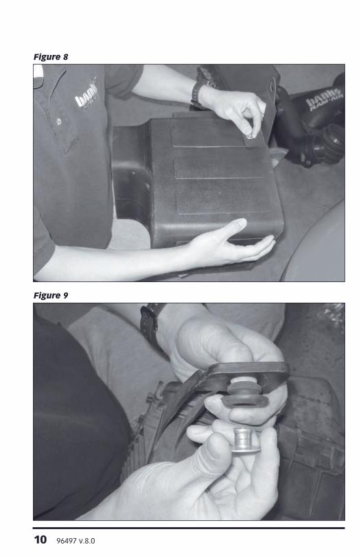
12. Locate the Banks air housing and Banks air housing bracket in your kit. Hand tighten the air housing bracket to air housing using supplied bolt and washer. See Figure 8.
13. Remove the steel insert and rubber grommet from the factory air housing. See Figure 9.
14. Insert the rubber grommet flange side down into the air housing bracket.
15. Press in the steel insert and make flush to rubber grommet.
16. Install the Banks air filter housing. Align the radiator core support bolt to the air housing bracket hole. Align the air filter housing holes to threaded Well-Nuts installed in fender bracket. See Figure 10.
Figure 5

96497 v.8.0 9
Figure 7- For Banks Super Scoop Installation Only
Figure 6- For Banks Super Scoop Installation Only
10 96497 v.8.0
Figure 8
Figure 9

96497 v.8.0 11
Figure 11
Figure 10

12 96497 v.8.0
Figure 13
Figure 12

96497 v.8.0 13
NOTE: The compressor supply and return lines may need to be slightly bent away from Banks air housing to provide clearance. Be careful not to break the condenser lines when adjusting clearance. See Figure 11.
17. Fasten the Banks air filter housing to the well-nuts by tightening the supplied 3⁄8 bolt and washer until snug. Tighten the air housing bracket nut to the radiator core support. Tighten the bracket to the air housing using an open-end wrench. See Figure 12.
18. Connect the Banks hose to the Banks inlet tube and tighten hose clamp.
NOTE: Ensure Banks hose is up to and touching the raised bead on the Banks intake tube. See Figure 13.
19. Install second hose clamp and leave loose.
20. Install Banks intake hose and intake tube to the compressor inlet.
NOTE: Ensure hose is flush against step on compressor inlet. Hand tighten the hose clamp. See Figure 13.
21. Place Banks air filter cover onto the Banks air filter housing.
22. Align intake tube with cover, and then tighten the hose clamp on turbo compressor inlet. See Figure 14.
NOTE: To provide additional clearence straighten the negative battery harness under the intake tube so that they lay flat and loose under the intake.
23. Locate the supplied PCV hose and insert one end into the intake tube. Insert the other end into the PCV tube. Make sure the hose is properly inserted.
For vehicles equipped with a factory Filter Minder
24. Remove factory filter minder from factory air housing. Remove rubber grommet from factory air housing.
Figure 14

14 96497 v.8.0
Figure 16
Figure 15
96497 v.8.0 15
Figure 18
Figure 17

16 96497 v.8.0
25. Install factory filter minder rubber grommet into the Banks cover. Insert the factory filter minder into rubber grommet.
All Vehicles26. Remove cover from housing. Install Banks bellows with hose clamps to Banks Intake tube.
27. Loosely install the hose clamp to the Banks air filter.
28. Install Banks air filter onto the Banks cover. Note the audible snap. Tighten the hose clamp on the air filter. Make sure the air filter is lined up with the alignment groove. See Figure 15.
29. Insert the Banks cover into the Banks bellows. Place cover on to housing and tighten the hose clamp. See Figure 16.
30. Using supplied screws fasten the banks cover to the air filter housing.
31. Remove the stock IAT and MAF sensors from the factory air housing.
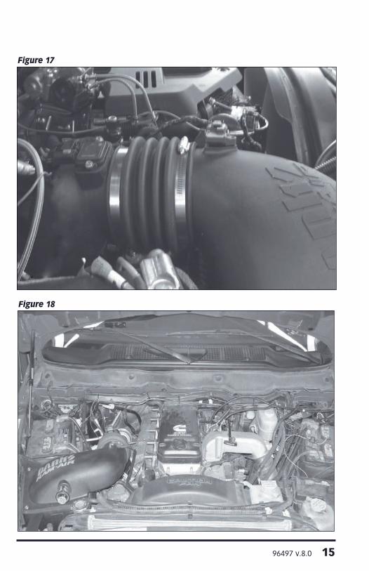
32. Install IAT sensor into Banks cover using supplied 6⁄32 screws. Locate the supplied MAF gasket and install over MAF sensor. Install MAF sensor and gasket into the Banks intake tube using the supplied 6⁄32 screws. See Figure 17.
NOTE: Ensure that o-rings are in good condition.
33. Connect the IAT and MAF connector to the IAT and MAF sensor.
NOTE: For added length in the IAT and MAF sensor wires, seperate the two wire bundles by CAREFULLY removing the tape holding them together. See Figure 19. Route harness away from the exhaust manifold heat shield.
34. Re-connect battery grounds. You have successfully completed the installation of the Banks Ram-Air Intake system. See Figure 18. Make sure to go over all hose clamps for tightness and connectors for a sure fit. Make sure that the intake tube is not touching any engine components.
Figure 19

96497 v.8.0 17
For Vehicles without a factory Filter Minder
35. Insert Banks Filter Minder Plug into hole on the Banks Air Intake Housing if your vehicle does not come equipped with a Filter Minder.
-END, SECTION 2-

18 96497 v.8.0
AIR-FILTERRESTRICTION
GAUGE
RESTRICTIVERED ZONE
Figure 20 Typical Air-Filter Restriction Gauge
Section 3FILTER MAINTENANCE
NotificationThe Banks Ram-Air Filter comes pre-oiled and no oiling is necessary for initial installation. Service the filter as specified in this Section of the manual.
1. Service Banks Ram Air Filter every 50-100,000 miles on street-driven applications. Service more often in off-road or heavy-dust conditions. If an air-filter restriction gauge is installed, then clean the element when the air-filter restriction gauge enters the restrictive red zone. See Figure 20.
2. Use Banks Ram Air Filter cleaning system (part # 90094), available from Gale Banks Engineering to service the Air Filter. Follow the instructions included with the cleaning system to clean and re-oil your Banks Ram
Air Filter. No gasoline cleaning, No steam cleaning, No caustic cleaning solutions, No strong detergents, No high pressure car wash, No parts cleaning solvents. Any of these No’s can cause harm to the cotton filter media plus SHRINK and HARDEN the rubber end caps.
CAUTION! Extremely fine dust from agriculture or off-road use will pull the oil from the element. Frequent re-oiling of the element’s clean side might be required. Completely service when practicable. For extra protection use an air-filter sealing grease on rubber ends of the element. Service only with Banks Ram-Air-filter cleaner and Banks Ram-Air-filter oil.
-END, SECTION 3-

96497 v.8.0 19
Notes

Gale Banks Engineering 546 Duggan Avenue • Azusa, CA 91702 (626) 969-9600 • Fax (626) 334-1743
Product Information & Sales: (888) 635-4565Customer Support: (888) 839-5600 Installation Support: (888) 839-2700
bankspower.com


![[XLS]petroleum.nic.inpetroleum.nic.in/dbt/banks/option1/CORPORATION BANK.xlsx · Web viewSRINAVASA ARCADE NEAR RAM MANDIR,BRAHMAVARA HEBRI ROAD,NEELAVAR KUNJAL-576258,UDUPI,KARNATAKA](https://static.fdocuments.in/doc/165x107/5af6b3187f8b9a154c91687b/xls-bankxlsxweb-viewsrinavasa-arcade-near-ram-mandirbrahmavara-hebri-roadneelavar.jpg)