Banks Git-Kit and Monster Exhaust - Amazon S3 · 2016-09-07 · 06/13/11 PN 96436 v.8.0 Banks...
20
06/13/11 PN 96436 v.8.0 Banks Git-Kit ® and Monster Exhaust 1999-2003 Ford Power Stroke 7.3L Turbo-Diesel F250/F350 Trucks THIS MANUAL IS FOR USE WITH • Monster exhaust, systeMs 48655-48657 • Monster exhaust w/ power elbow, systeMs 48658-48660 • power elbow, asseMbly 48651, 48652, 48661, 48662 • Git-Kit systeMs 47510-47513 Gale banks engineering 546 Duggan avenue • azusa, CA 91702 (626) 969-9600 • Fax (626) 334 - 1743 product information & sales: (888) 635-4565 Customer support: (888) 839-5600 installation support: (888) 839-2700 bankspower.com ©2011 Gale banks engineering Ow ner ’ sManual with installation instructions
Transcript of Banks Git-Kit and Monster Exhaust - Amazon S3 · 2016-09-07 · 06/13/11 PN 96436 v.8.0 Banks...

06/13/11 PN 96436 v.8.0
Banks Git-Kit® and Monster Exhaust 1999-2003 Ford Power Stroke 7.3L Turbo-Diesel F250/F350 Trucks
THIS MANUAL IS FOR USE WITH
• Monster exhaust, systeMs 48655-48657
• Monster exhaust w/ power elbow, systeMs 48658-48660
• power elbow, asseMbly 48651, 48652, 48661, 48662
• Git-Kit systeMs 47510-47513
Gale banks engineering 546 Duggan avenue • azusa, cA 91702 (626) 969-9600 • Fax (626) 334-1743
product information & sales: (888) 635-4565Customer support: (888) 839-5600 installation support: (888) 839-2700
bankspower.com
©2011 Gale banks engineering
Owner’sManualwith installation instructions

2 96436 v.8.0
Banks Power Elbow (P/N 48651-48652, 48661-48663)
- reduces stock outlet and pipe backpressure
Banks Ram-Air Intake System(P/N 96885)
- increases your airflow over stock. - adds power, improves fuel economy, lowers eGts and reduces smoke.
Banks Techni-Cooler® System(P/N 25971-25973)
- provides increased air flow to the engine by increasing air density for more increased power, lower eGts and improved fuel economy.
Banks TransCommand(P/N 62570)
- produces smooth, firm, light-throttle shifts and solid, decisive heavy-load shifts.
- eliminates excessive clutch slippage
Banks Billet Torque Converter(P/N 72521)
- higher torque capacity over stock- lockup clutch is slip-resistant so transmission fluids stay cooler and transmission life is prolonged.
Banks Diesel TunerSix-Gun (P/N 66513-66515)Big Hoss (P/N 66505)
- adds power safely to your vehicle
- engine and transmission safeguards
- Change power levels on-the-fly
Thermocouple- add a temperature limiting function to your Diesel tuner
Banks QuickTurbo(P/N 24456-24457)
- More boost through the powerband- Does not over-boost- turbo-diesel efficiency
Products available from Banks Power for the ‘99-03 Ford 7.3L ‘99-03 Ford 7.3L

96436 v.8.0 3
For More Information please call (888) 635-4565or Visit us online @ www.bankspower.com
Banks Brake(P/N 55202-55207)
- increases the stopping power of your truck and extends the service life of your brakes
Banks SmartLock(P/N 55266)
- reduces wear on transmission- locks torque Converter and raisestrans-line pressure
- works with banks exhaust brake
AutoMind Programmer(P/N 66100)
- Contains banks tunes that boost your vehicles hp, torque and MpG.
- Displays a host of critical engine functions
- provides “service technician” diagnostic capabilities
- has upgradeable functionality, so it will never be out of date
Banks Git-Kit Systems(P/N 47401, 47511-47514)Contains:
- Monster exhaust- big hoss Module
Banks Stinger SystemsContains:
- ram-air intakeFilter- Monster exhaust - big hoss Module- big head wastegate actuator
Banks PowerPack SystemsContains:
- ram-air intake Filter- Monster exhaust- Quick-turbo - transCommand- techni-Cooler system- big head wastegate actuator
Banks Six-Gun Bundle(P/N 46594-46613)Contains:
- ram-air intake Filter- Monster exhaust- six-Gun tuner- transCommand- big head wastegate actuator
Banks Big Hoss Bundle(P/N 46623-46643)Contains:
- ram-air intake Filter- Monster exhaust- six-Gun tuner- transCommand- big head wastegate actuator- techni-Cooler system- big hoss Module- power elbow
Banks Power Combo 1Contains:
- big hoss Module- transCommand- big head wastegate actuator
Banks Power Combo 2Contains:
- six-Gun tuner- transCommand- big head wastegate actuator
Banks Power Combo 3Contains:
- big hoss Module- Monster exhaust
Banks Power Combo 4Contains:
- big hoss Module- transCommand- big head wastegate actuator- six-Gun tuner
4 96436 v.8.0
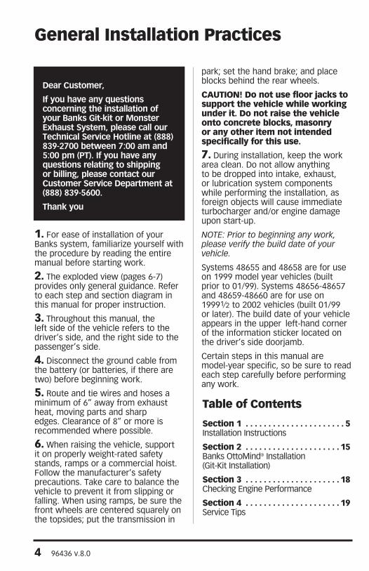
Dear Customer,
If you have any questions concerning the installation of your Banks Git-kit or Monster Exhaust System, please call our Technical Service Hotline at (888) 839-2700 between 7:00 am and 5:00 pm (PT). If you have any questions relating to shipping or billing, please contact our Customer Service Department at (888) 839-5600.
Thank you
1. For ease of installation of your banks system, familiarize yourself with the procedure by reading the entire manual before starting work.
2. the exploded view (pages 6-7) provides only general guidance. refer to each step and section diagram in this manual for proper instruction.
3. throughout this manual, the left side of the vehicle refers to the driver’s side, and the right side to the passenger’s side.
4. Disconnect the ground cable from the battery (or batteries, if there are two) before beginning work.
5. route and tie wires and hoses a minimum of 6” away from exhaust heat, moving parts and sharp edges. Clearance of 8” or more is recommended where possible.
6. when raising the vehicle, support it on properly weight-rated safety stands, ramps or a commercial hoist. Follow the manufacturer’s safety precautions. take care to balance the vehicle to prevent it from slipping or falling. when using ramps, be sure the front wheels are centered squarely on the topsides; put the transmission in
park; set the hand brake; and place blocks behind the rear wheels.
CAuTIoN! Do not use floor jacks to support the vehicle while working under it. Do not raise the vehicle onto concrete blocks, masonry or any other item not intended specifically for this use.
7. During installation, keep the work area clean. Do not allow anything to be dropped into intake, exhaust, or lubrication system components while performing the installation, as foreign objects will cause immediate turbocharger and/or engine damage upon start-up.
Note: Prior to beginning any work, please verify the build date of your vehicle.
systems 48655 and 48658 are for use on 1999 model year vehicles (built prior to 01/99). systems 48656-48657 and 48659-48660 are for use on 19991⁄2 to 2002 vehicles (built 01/99 or later). the build date of your vehicle appears in the upper left-hand corner of the information sticker located on the driver’s side doorjamb.
Certain steps in this manual are model-year specific, so be sure to read each step carefully before performing any work.
General Installation Practices
Table of Contents
Section 1 . . . . . . . . . . . . . . . . . . . . . . 5installation instructions
Section 2 . . . . . . . . . . . . . . . . . . . . . 15banks ottoMind® installation (Git-Kit installation)
Section 3 . . . . . . . . . . . . . . . . . . . . . 18Checking engine performance
Section 4 . . . . . . . . . . . . . . . . . . . . . 19service tips

96436 v.8.0 5
1. raise the vehicle on a hoist or safety stands to provide access to the exhaust system. loosen the clamp at the front of the muffler and pry the muffler and tailpipe hanger pins from the rubber hangers (spray lubricant will ease hanger removal). remove the muffler and tailpipe from the vehicle. Cutting the tailpipe may ease the process of removal.
2. if your vehicle is equipped with a catalytic converter, mark a point 4” from the forward edge of the weld at the inlet of the catalytic converter on the downward facing side of the pipe (see Figure 1).
3. remove the remaining portion of the exhaust system from the vehicle. retain the t.o.p. V-band clamp for reuse (on systems, 48658 and 48661 use supplied V-band clamp).
the converter must be reinstalled in the vehicle. remove the intermediate pipe from the outlet end of the converter. at the mark previously made, cut through the converter pipe square with the remaining face of the pipe as shown in Figure 1.
WARNING: At the outlet of each exhaust manifold, locate the short section of tubing that feeds exhaust up to the turbocharger. Check these tubes to ensure
that they are not loose, as we have found several new vehicles with exhaust leaks in this area. Correct this condition now or soon after installation of the Monster exhaust components to eliminate dangerous exhaust leaks and poor turbocharger performance.
IMPORTANT: The catalytic converter should be inspected. Diesel catalysts may become plugged with soot and can cause a restriction to exhaust flow, impeding performance. Shine a powerful flashlight into the inlet end of the converter. Observe the light through the other end of the converter. The full circle of the flashlight should be visible without any blockage in the gridwork of the catalyst. If excessive soot is observed, the catalyst may need to be cleaned. TAKE PRECAUTIONS to avoid blowing soot toward the work area or where it could be inhaled. ALWAYS use breathing protection. Also inspect the catalyst for damage (i.e. chips, bent corners, etc.) to the gridwork. If your catalytic converter is damaged, it may be covered under your vehicle’s emissions warranty.
if a banks power elbow is being installed, follow steps 4-11 below. otherwise, skip to step 12.
Section 1INSTALLATIoN INSTRuCTIoNS
Figure 1

6 96436 v.8.0
General AssemblyFigure 2
Item # Part # Description QTY
1 53495 power elbow 1
2a 55210/55211
turbine outlet pipe, for use with power elbow 1
2b 53585/53589
turbine outlet pipe, automatic/Manual trans 1
3 53586/53590
intermediate pipe, front, automatic/Manual trans 1
3a 53588 intermediate pipe, front, w/o Catalyic Converter 1
4 53506 intermediate pipe, rear 1
4a 53508 intermediate pipe, rear, w/o Catalyic Converter 1
5 * extension pipe (optional) 1
5a 53519 hanger, super-Cab long bed (optional) 1
5b 91789 bolt, M8 - 1.25 x 30mm (optional) 2
6 53800 Dynaflow muffler 1
7 53524 tailpipe, Front 1
8 53525 tailpipe, rear 1
*53513 for CCsb, 53514 for eClb & 53515 for CClb
7
11
89
20
65
11
5
21
5

96436 v.8.0 7
9 52383 tailpipe tip, 5” 1
10 52468 exhaust Clamp, 31⁄2” 2
11 52470 exhaust Clamp, 4” 3
12 26002 heat shield blanket 1
13 26096 spacer, 3⁄8 x 5⁄8 “ 2
14 91792 bolt, 8mm x 1.25 x 45mm hex 2
15 92864 hose Clamps, # 64 3
16 92884 V-band clamp (system 48658 & 48651 only) 1
17 91922 bolt, M10-1.5x20mm (systems 48659-48660 only) 1
18 91455 bolt, 3⁄8-16x3⁄4” (systems 48659-48660 only) 1
19 55036 support bracket (systems 48659-48660 only) 1
20 53453 Front Muffler hanger Clamp 1
21 53454 rear Muffler hanger Clamp 1
22 62545 warm-up Valve Module 1
23 96009 urocal, “banks power” 2
23
2b
2a
3a
11
4a
15 16
1
17 19
18
22
11
11
3
10
14
13
5a
5b
10
4

8 96436 v.8.0
4. on the passenger side of the vehicle, temporarily remove the manifold absolute pressure (Map) sensor (Figure 3) from its mounting location by removing the three nuts from the mounting studs. save the nuts for reinstallation later. set the Map sensor out of the way by resting it in the intake valley of the engine.
5. remove both driver- and passenger-side boost tubes and the intake plenum from the vehicle to allow access to the rear of the turbocharger.
6. Disengage the exhaust backpressure control rod by sliding the cover on the end of the rod back toward the turbocharger and pulling
the rod downward. this rod is below the turbine housing; it is not the wastegate actuator rod that runs across the top of the turbocharger.
Note: the exhaust backpressure control rod must be left in its place and will not be reconnected. Do Not attempt to secure the rod or bend in any manner as this may cause oil to leak from pedestal.
7. locate the engine lifting hook at the rear of the engine on the passenger side, bolted to the cylinder head. remove the lifting hook. this will allow clearance for the installation of the power elbow. it is not necessary to re-install the hook.
Figure 3
96436 v.8.0 9
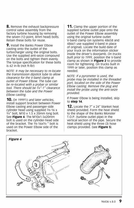
8. remove the exhaust backpressure control valve assembly from the factory turbine housing by removing the seven (12-point, 8mm head) bolts. retain these bolts for reuse.
9. install the banks power elbow casting onto the outlet of the turbocharger using the original bolts. use the supplied anti-seize compound on the bolts and tighten them evenly. the torque specification for these bolts is 62 in-lb (not ft-lb!)
Note: It may be necessary to re-locate the transmission dipstick tube to allow clearance for the V-band clamp at outlet of Power elbow. the tube can be re-located with a prybar or similar tool. there should be 3⁄4”-1” clearance between the tube and the Power elbow casting.
10. on 19991⁄2 and later vehicles, install support bracket between power elbow casting and passenger-side cylinder head using supplied 3⁄8-16 x 3⁄4” bolt, M10 x 1.5 x 20mm long bolt. see Figure 4. the M10x1.5x20mm bolt is used on the cylinder-head side of the bracket. the 3⁄8-16x3⁄4 “ bolt is used on the power elbow side of the bracket.
11. Clamp the upper portion of the supplied turbine outlet pipe onto the outlet of the power elbow assembly using the original turbine outlet V-band clamp (on systems 48658 and 48661 use supplied V-band in place of original). locate the build date of your truck on the information sticker inside the driver’s doorjamb. on trucks built prior to 1999, position the V-band clamp as shown in Figure 2 to provide room for tightening. on trucks built in 1999 or later, position this clamp as needed.
Note: If a pyrometer is used, the probe may be installed in the threaded port, located on the side of the Power elbow casting. Remove the plug and install the probe using the anti-seize provided.
if power elbow is being installed, skip to step 14.
12. locate the 7” x 24” blanket heat shield provided. Form the heat shield to the shape of the banks Monster t.o.p. (turbine outlet pipe) in the vertical section of the pipe. secure the heat shield using the three (3) hose clamps provided. (see Figure 5).
Figure 4

10 96436 v.8.0
13. reusing the saved V-band clamp previously put aside, loosely clamp the upper portion of the turbine outlet pipe to the factory warm-up valve outlet. Do not tighten at this time.
Note: on some Power Strokes a ground strap is bolted on the back of the cylinder head. this bolt may interfere with the Banks turbine outlet pipe. If so, remove the bolt and relocate it in the cylinder head.
14. on 2002 & 2003 models only, it is necessary to relocate the factory-installed frame-mounted hanger pin that is located behind the transmission crossmember.
A. remove the two (2) nuts that hold the frame-mounted hanger pin to the frame rail, save for reinstallation later. remove the frame-mounted hanger pin from vehicle.
B. remove the two (2) 8mm studs from the frame-mount hanger pin.
Note: Studs are pressed into hanger pin and will require the
use of a hammer or small press to remove.
C. reinstall the frame-mounted hanger pin using the two (2) 5⁄8” long steel spacers, two (2) 8mm x 1.25 x 45mm bolts and the two (2) 8mm nuts (removed in Step A above). see Figure 6 for proper assembly sequence. torque fasteners to 18 ft-lb.
15. place a 4” exhaust clamp on the turbine outlet pipe. install the front intermediate pipe onto the turbine outlet pipe, aligning the hanger pin in the rubber hanger. For catalytic converter models, place a 31⁄2” clamp on the end of the front intermediate pipe and reinstall the catalytic converter (where you have cut per step 2). put another 31⁄2” clamp on the outlet of the catalytic converter. For models without catalytic converters, place a 4” clamp on the outlet of the front intermediate pipe (see Figure 2).
Figure 5

96436 v.8.0 11
16. For Standard Cab long-bed vehicles: it will be necessary to cut 43⁄4” off the rear intermediate pipe supplied in the kit. the hanger will be removed with the unused portion of the pipe (see Figure 7). install the rear intermediate pipe.
For Super-cab short-bed: install the rear intermediate pipe as supplied (no cut required).
For Crew-cab short-bed: install the rear intermediate pipe. place a 4” clamp on the end of the rear intermediate pipe and install the extension pipe kit (p/n 53516).
For Super-cab long-bed: remove the rear frame mounted hanger (see Figure 2) and install the supplied frame mounted hanger in its place, using the two 8mm x 30mm hex bolts supplied and re-using the two 8mm nuts previously removed. install the rear intermediate pipe. place
a 4” clamp on the end of the rear intermediate pipe and install the extension pipe kit (p/n 53517).
For Crew-cab long-bed: install the rear intermediate pipe. place a 4” clamp on the end of the rear intermediate pipe and install the extension pipe kit (p/n 53518).
17. install the single pin front hanger clamp onto the rear of the intermediate pipe with the hanger pin on the inside facing the muffler. insert the hanger pin into the vehicle’s rubber grommet. install the inlet of the banks Monster muffler to the intermediate pipe. install the dual pin rear hanger clamp onto the outlet of the Monster muffler with the hanger pins on the inside, facing the muffler. insert the two hanger pins into the vehicle’s rubber grommets. orient the muffler such that the banks logo is visible from the passenger side.
Figure 6

12 96436 v.8.0
18. route the Front Tailpipe over the rear axle and install into the banks Muffler. loosely snug the rear muffler hanger clamp.
19. install a 4” exhaust clamp onto the outlet of the front tailpipe. install the Rear Tailpipe into the front tailpipe. install the rear tailpipe hanger pin into the corresponding vehicle rubber hanger. loosely snug the 4” exhaust clamp.
20. slip the 5” Monster tailpipe tip on. Keep the wrapping on for now. For a Fleet-side truck the 5” tip should be hung 1in past the end of the tailpipe. For a dually, the tip should be 31⁄2” past the end of the tail pipe. snug up the clamp.
21. position all the exhaust components such that all the hanger pins are parallel with the frame pins and all exhaust tubing is located properly. lightly tighten the clamps to maintain position. the tailpipe tip should be positioned 1-11⁄2 “ below the bottom edge of the fender. all hangers should be hanging slightly forward to allow for heat expansion of the exhaust tubing (see Figure 8).
22. with everything positioned properly, begin to tighten the clamps starting with the ones closest to the turbo and working your way back. torque V-band clamp to 80 in-lbs. torque all remaining clamps to 35 ft-lbs.
23. the 2-pin warm-up valve module needs to be installed onto the warm-up valve connector on the vehicle wire harness. on the pedal stool under the turbocharger, disconnect the 2-pin connector. attach the 2-pin connector to the banks warm-up valve module and zip-tie the module and wire harness away from any moving parts. see Figure 9
24. your system includes two banks power logos that have been designed to compliment the Ford badging on your truck. we have provided measurements, which will allow you to place these logos in a position that gives a clean factory look. see Figure 10.
25. remove protective wrapping from tailpipe tip. the Monster exhaust installation is now complete.
-enD, seCtion 1-
Figure 7

96436 v.8.0 13
Figure 8
Figure 9

14 96436 v.8.0
Figure 10

96436 v.8.0 15
1. be certain battery ground cables have been disconnected.
2. locate the engine control unit (eCu) under the dash toward the left-hand side of the vehicle. it will be housed in a black plastic box bolted to the side of the vehicle. loosen the bolt attaching the electrical connector to the eCu on the engine compartment side. this will be the connector closest to the left front fender. see Figure 11.
3. loosen the two 7mm hex bolts on the rear portion of the black plastic box. remove the box and eCu from the vehicle together. pull the eCu out of the plastic box.
4. note the code printed on the plastic cap on the back of the eCu. this code should compare to the code printed on the banks ottoMind box label. pry the plastic cap from the rear of the eCu using a small screwdriver, exposing the printed circuit board edge connector inside. retain the plastic cap. the connector will be coated with grease and a clear silicone type coating, which must be completely removed before installing the banks ottoMind engine calibration module.
Section 2BANKS oTToMIND® INSTALLATIoN (GIT-KIT INSTALLATIoN)
Figure 11

16 96436 v.8.0
5. using a 5.5mm nut driver, loosen and remove the six bolts that hold the case of the eCu together. open the case of the eCu, being careful not to lose the plastic spacer or damage any circuitry inside the eCu.
6. Clean both sides of the connector. First, clean the white grease off with a tissue. next, scrape the clear silicone type coating from the connector fingers with the abrasive square provided. it is very important to clean both sides of the board in order to have a good connection between the eCu and the banks ottoMind module. it is only necessary to clean the connector fingers. be careful not to damage any circuit traces on the board further inside the eCu.
7. orient the module so that its edges line up with the edges of the eCu case. if the edges do not line up, the module is rotated 180° off. place the ottoMind module over the connector, and press firmly to set the connection. Do not ForCe the ottoMind onto the connector, as damage may result to either the eCu or the module. if the module does not install with firm pressure, check the orientation and try again.
8. using a band saw or hacksaw cut a portion of the black plastic case away allowing the ottoMind to reside in its proper location. see Figure 12. reinstall the eCu with the black plastic box, making sure the ground tab is still in place at the lower mounting
point. reattach the wiring harness to the eCu and tighten the retaining bolt. be careful that all the pins are aligned correctly, as it is possible to bend the pins of the eCu and do permanent damage! reconnect the batteries.
9. Find, supplied in the kit, the blaCK wire with a ring terminal on one side and a male “fast-on” blade terminal on the other. install the red “t-tap” connector on the center wire of the Map sensor as far from the sensor as possible. pull the wire out of the convoluted plastic tube near the top of the firewall and squeeze the t-tap onto the wire with pliers. see Figure 13. attach one end of the blaCK wire to the t-tap and the ring terminal end to the ground strap lug on the firewall.
10. Check the operation of the ottoMind and eCu. the vehicle may not start if the coating on the eCu connector is not completely removed or if there is a mismatch of codes. a quick indication of module connections that are not cleaned properly is that the “wait to start” indicator will fail to light and the “Check engine” warning indicator will stay lit after the key is switched on. if the engine fails to start, re-clean the eCu connector, reinstall the module and try again. if the problem persists, contact customer service at Gale banks engineering to confirm that the eCu and ottoMind codes match.
-enD, seCtion 2-

96436 v.8.0 17
Figure 13
Figure 12

18 96436 v.8.0
start the engine and allow it to warm up. Drive the vehicle, listening for any exhaust leaks or rattles. adjust and tighten clamps or reposition the piping if required. when positioning of piping is finalized, it is a good practice to place tack welds at any slip joints in the exhaust system to prevent slippage.
Note: the exhaust may smoke slightly after initial startup. this is normal and will go away shortly as the grease used in the bending process burns off the inside of the piping.
we recommend that the exhaust gas temperature eGt not exceed 1100°F at the outlet of the turbine housing and that engine oil temp not exceed 250°F. optimum oil temperature is around 230°F.
Note: optional (eGt) oil temperature gauge are available from Gale Banks engineering.
-enD, seCtion 3-
Section 3CHECKING ENGINE PERFoRMANCE

96436 v.8.0 19
1. if the need should arise for you to have your vehicle serviced, the banks ottoMind should be removed from the engine control unit (eCu). it is common for the service provider to connect a computer diagnostic link to the vehicle regardless of the type of service being performed. when the ottoMind is installed, the computer will return a code that indicates a memory fault with the vehicle eCu. the suggested repair for a fault of this type is replacement of the eCu.
2. the operation of the ottoMind is such that the computer is directed to reference certain information in the ottoMind rather than the eCu. therefore, the memory fault that occurs is not an eCu failure, but rather the presence of an electronic device that the diagnostic computer cannot identify.
3. to avoid confusion about whether or not an eCu is properly functioning, simply remove the ottoMind from the eCu before having the vehicle serviced, and reinsert the plastic cap in the eCu access port. the ottoMind can be easily accessed from inside the truck, and it is unnecessary to remove the computer from the vehicle. the ottoMind may be reinstalled after the service is complete.
4. it is also not uncommon for a service provider to update the program in the vehicle eCu. if this occurs, it is possible that the programming in the ottoMind will no longer match the eCu program. if you experience any difficulty with the operation of the banks ottoMind after service, check with the service provider to determine if an update was performed. then contact customer service at Gale banks engineering for an updated ottoMind, if necessary.
-enD, seCtion 4-
Section 4SERvICE TIPS

Gale banks engineering 546 Duggan avenue • azusa, cA 91702 (626) 969-9600 • Fax (626) 334-1743
product information & sales: (888) 635-4565Customer support: (888) 839-5600 installation support: (888) 839-2700
bankspower.com