
Bandwidth Management in DM814x / DM385 fileTI Confidential – NDA Restrictions Bandwidth Management...
25
TI Confidential – NDA Restrictions Bandwidth Management in DM814x / DM385 1 11 June 2013
Transcript of Bandwidth Management in DM814x / DM385 fileTI Confidential – NDA Restrictions Bandwidth Management...

TI Confidential – NDA Restrictions
Bandwidth Management in
DM814x / DM385
1
11 June 2013
TI Confidential – NDA Restrictions
DM385 and DM814x
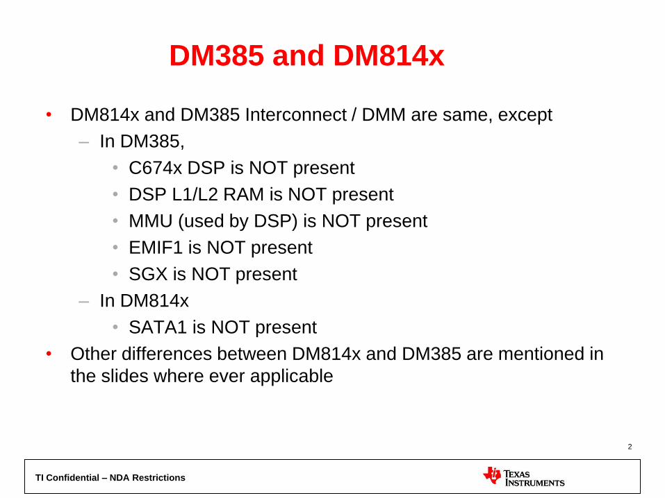
• DM814x and DM385 Interconnect / DMM are same, except
– In DM385,
• C674x DSP is NOT present
• DSP L1/L2 RAM is NOT present
• MMU (used by DSP) is NOT present
• EMIF1 is NOT present
• SGX is NOT present
– In DM814x
• SATA1 is NOT present
• Other differences between DM814x and DM385 are mentioned in
the slides where ever applicable
2

TI Confidential – NDA Restrictions
DM814x/DM385 Interconnect overview
• Master IP – Initiates bus requests
• Slave IP – Responds to bus requests
• L3 Interconnect – Routes/arbitrates bus requests between Masters and
Slaves
• Dynamic Memory Manager (DMM) – Provides interleaved view of two EMIF’s in single address space (DM814x)
– Provides non-interleaved view of single EMIF in single address space (DM385)
• External Memory Interface (EMIF) - Queues/schedules requests to DRAM
ARM
Cortex A8
C674x
DSP
Imaging
SubsystemHDVICP HDVPSSTC
0
TC
1
TC
2
TC
3
M
M
U
Other
Periphs
DMM
EMIF0 EMIF1
L3 Interconnect
DSP L1/L2
SRAM
OCMC
RAM
Other
Periphs
SGX PCIe
Serial
PortsGPMC
EDMA3 CC
128-b
64-b
32-b
Master IP
Slave IP
Interconnect IP
Legend
Only in DM814x
3
TI Confidential – NDA Restrictions
Interconnect Key Characteristics
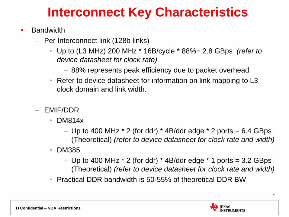
• Bandwidth
– Per Interconnect link (128b links)
• Up to (L3 MHz) 200 MHz * 16B/cycle * 88%= 2.8 GBps (refer to
device datasheet for clock rate)
– 88% represents peak efficiency due to packet overhead
• Refer to device datasheet for information on link mapping to L3
clock domain and link width.
– EMIF/DDR
• DM814x
– Up to 400 MHz * 2 (for ddr) * 4B/ddr edge * 2 ports = 6.4 GBps
(Theoretical) (refer to device datasheet for clock rate and width)
• DM385
– Up to 400 MHz * 2 (for ddr) * 4B/ddr edge * 1 ports = 3.2 GBps
(Theoretical) (refer to device datasheet for clock rate and width)
• Practical DDR bandwidth is 50-55% of theoretical DDR BW
4
TI Confidential – NDA Restrictions
DM814x / DM385 Detailed Connectivity for key
masters/slaves
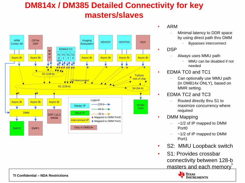
• ARM
– Minimal latency to DDR space
by using direct path thru DMM
• Bypasses interconnect
• DSP
– Always uses MMU path
• MMU can be disabled if not
needed
• EDMA TC0 and TC1
– Can optionally use MMU path
(in DM814x ONLY), based on
MMR setting.
• EDMA TC2 and TC3
– Routed directly thru S1 to
maximize concurrency where
required
• DMM Mapping
– ~1/2 of IP mapped to DMM
Port0
– ~1/2 of IP mapped to DMM
Port1
• S2: MMU Loopback switch
• S1: Provides crossbar
connectivity between 128-b
masters and each memory
ARM
Cortex A8
C674x
DSP
Imaging
SubsystemHDVICP HDVPSS
TC
0
TC
1
TC
2
TC
3
M
M
U
DMM
EMIF0 EMIF1
L3 Interconnect
DSP L1/L2
SRAM
OCMC
RAM
SGX
EDMA3 CC
Async Br Async Br Async Br Async Br Async Br Async Br
Async Br Async Br Async Br
S2 (128-b)
S1 (128-b)S4 (64-b)
To/from
rest of chip
128-b
64-b
32-b
Master IP
Slave IP
Interconnect IP
Legend
Mapped to DMM Port0
Mapped to DMM Port1
W R
Only in DM814x
5

TI Confidential – NDA Restrictions
Bandwidth Management Overview
• DM814x has Cortex-A8 , HDVICP , HDVPSS , EDMA , Ducati /M3, DSP , USB , GMAC , ISS, etc as data traffic initiators.
• DM385 has Cortex-A8 , HDVICP , HDVPSS , EDMA , Ducati /M3, USB , GMAC , etc as data traffic initiators.
• Above initiators transfer data to/from targets such as DDR memory, OCMC RAM , other processors memory & peripherals.
• Each initiator have programmable
– pressure control for interconnect.
– priority control for EMIF
• This would enable each initiator to get latency and/or bandwidth they require.
6
TI Confidential – NDA Restrictions
L3 Interconnect Pressure
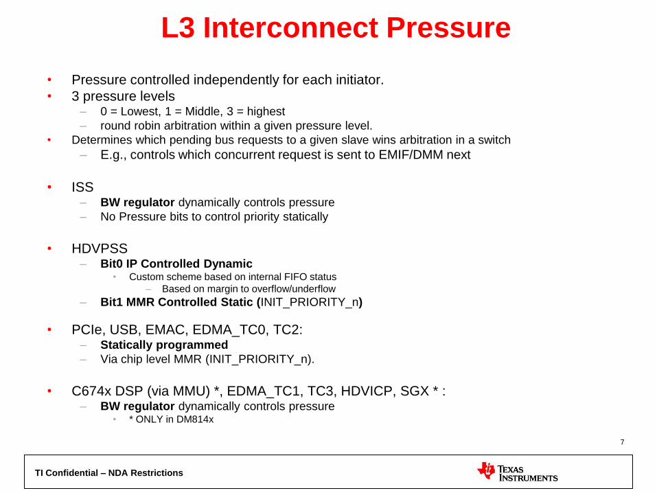
• Pressure controlled independently for each initiator.
• 3 pressure levels – 0 = Lowest, 1 = Middle, 3 = highest
– round robin arbitration within a given pressure level.
• Determines which pending bus requests to a given slave wins arbitration in a switch
– E.g., controls which concurrent request is sent to EMIF/DMM next
• ISS – BW regulator dynamically controls pressure
– No Pressure bits to control priority statically
• HDVPSS – Bit0 IP Controlled Dynamic
• Custom scheme based on internal FIFO status
– Based on margin to overflow/underflow
– Bit1 MMR Controlled Static (INIT_PRIORITY_n)
• PCIe, USB, EMAC, EDMA_TC0, TC2: – Statically programmed
– Via chip level MMR (INIT_PRIORITY_n).
• C674x DSP (via MMU) *, EDMA_TC1, TC3, HDVICP, SGX * : – BW regulator dynamically controls pressure
• * ONLY in DM814x
7
TI Confidential – NDA Restrictions
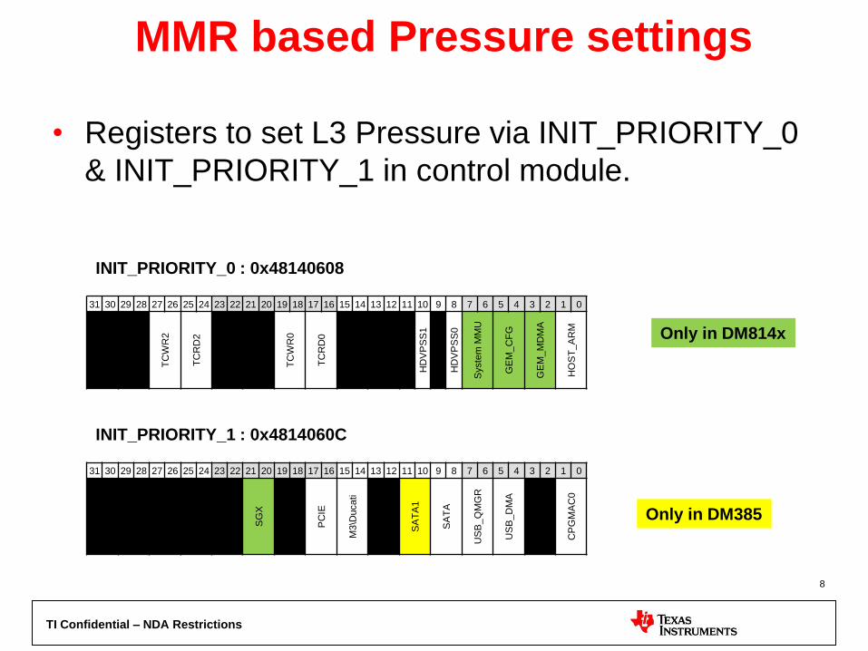
MMR based Pressure settings
• Registers to set L3 Pressure via INIT_PRIORITY_0
& INIT_PRIORITY_1 in control module.
31 30 29 28 27 26 25 24 23 22 21 20 19 18 17 16 15 14 13 12 11 10 9 8 7 6 5 4 3 2 1 0
TC
WR
2
TC
RD
2
TC
WR
0
TC
RD
0
HD
VP
SS
1
HD
VP
SS
0
Syste
m M
MU
GE
M_C
FG
GE
M_M
DM
A
HO
ST
_A
RM
INIT_PRIORITY_0 : 0x48140608
INIT_PRIORITY_1 : 0x4814060C
31 30 29 28 27 26 25 24 23 22 21 20 19 18 17 16 15 14 13 12 11 10 9 8 7 6 5 4 3 2 1 0
SG
X
PC
IE
M3\D
ucati
SA
TA
1
SA
TA
US
B_Q
MG
R
US
B_D
MA
CP
GM
AC
0
Only in DM814x
Only in DM385
8
TI Confidential – NDA Restrictions
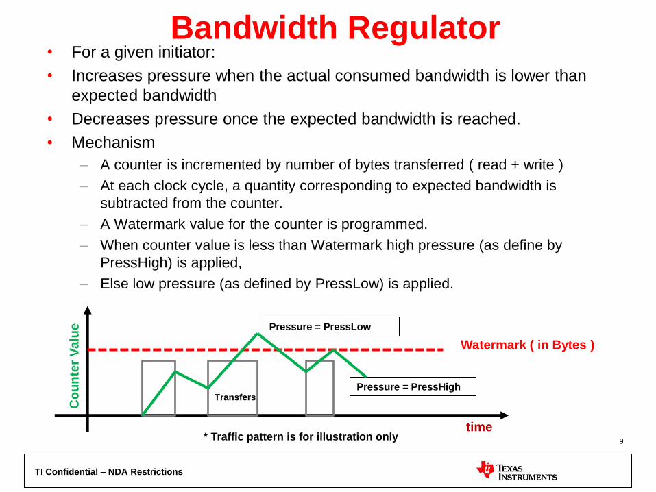
Bandwidth Regulator • For a given initiator:
• Increases pressure when the actual consumed bandwidth is lower than
expected bandwidth
• Decreases pressure once the expected bandwidth is reached.
• Mechanism
– A counter is incremented by number of bytes transferred ( read + write )
– At each clock cycle, a quantity corresponding to expected bandwidth is
subtracted from the counter.
– A Watermark value for the counter is programmed.
– When counter value is less than Watermark high pressure (as define by
PressHigh) is applied,
– Else low pressure (as defined by PressLow) is applied.
Watermark ( in Bytes )
time
Pressure = PressLow
Pressure = PressHigh
Co
un
ter
Valu
e
* Traffic pattern is for illustration only
Transfers
9

TI Confidential – NDA Restrictions
Setting up a Bandwidth Regulator Bandwidth : 0x08
Watermark: 0x0C
Press: 0x10
Required Bandwidth
Bus Freq / (2^5)
31 30 29 28 27 26 25 24 23 22 21 20 19 18 17 16 15 14 13 12 11 10 9 8 7 6 5 4 3 2 1 0
Bandw
idth
31 30 29 28 27 26 25 24 23 22 21 20 19 18 17 16 15 14 13 12 11 10 9 8 7 6 5 4 3 2 1 0
Wate
rma
rk
31 30 29 28 27 26 25 24 23 22 21 20 19 18 17 16 15 14 13 12 11 10 9 8 7 6 5 4 3 2 1 0
Cle
ar
His
tory
Clear History : 0x014
MovingWindow * Bandwidth
Write 1 after updating
other registers
31 30 29 28 27 26 25 24 23 22 21 20 19 18 17 16 15 14 13 12 11 10 9 8 7 6 5 4 3 2 1 0
Pre
ss L
ow
Pre
ss H
igh Press Low should be
less than equal to
Press High
10
TI Confidential – NDA Restrictions
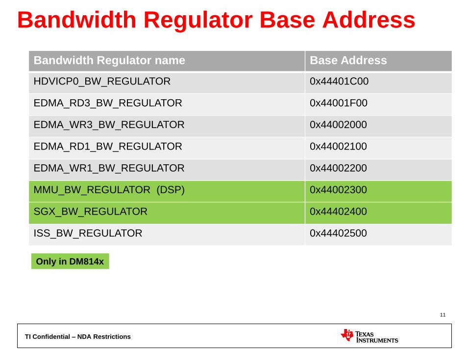
Bandwidth Regulator Base Address
Bandwidth Regulator name Base Address
HDVICP0_BW_REGULATOR 0x44401C00
EDMA_RD3_BW_REGULATOR 0x44001F00
EDMA_WR3_BW_REGULATOR 0x44002000
EDMA_RD1_BW_REGULATOR 0x44002100
EDMA_WR1_BW_REGULATOR 0x44002200
MMU_BW_REGULATOR (DSP) 0x44002300
SGX_BW_REGULATOR 0x44402400
ISS_BW_REGULATOR 0x44402500
Only in DM814x
11
TI Confidential – NDA Restrictions
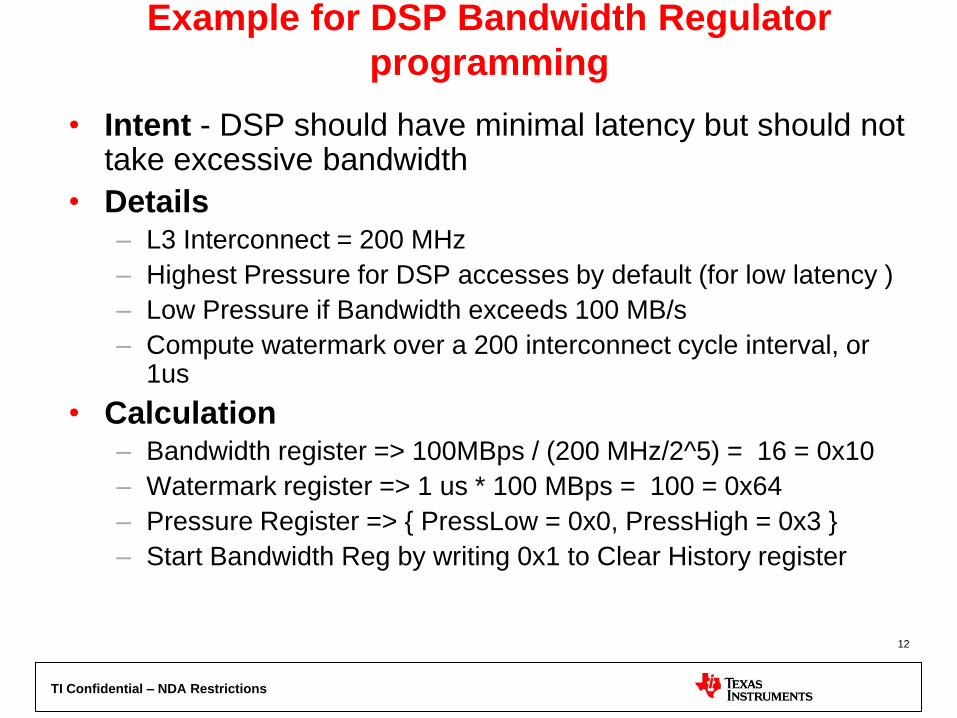
Example for DSP Bandwidth Regulator
programming
• Intent - DSP should have minimal latency but should not take excessive bandwidth
• Details – L3 Interconnect = 200 MHz
– Highest Pressure for DSP accesses by default (for low latency )
– Low Pressure if Bandwidth exceeds 100 MB/s
– Compute watermark over a 200 interconnect cycle interval, or 1us
• Calculation – Bandwidth register => 100MBps / (200 MHz/2^5) = 16 = 0x10
– Watermark register => 1 us * 100 MBps = 100 = 0x64
– Pressure Register => { PressLow = 0x0, PressHigh = 0x3 }
– Start Bandwidth Reg by writing 0x1 to Clear History register
12

TI Confidential – NDA Restrictions
Example for HDVICP Bandwidth
Regulator programming
• Intent - HDVICP should have 1GB/s bandwidth & should not take excessive bandwidth
• Method – L3 Interconnect = 200 MHz
– Medium Pressure for HDVICP accesses by default ( to ensure bandwidth)
– Low Pressure if Bandwidth exceeds 1GBps
– Compute watermark over 500 interconnect cycles, or 2.5 us
• Calculation – Bandwidth register => 1000MB/s / (200 MHz/2^5) = 160 = 0xA0
– Watermark register => 2.5 us * 1000 MB/s = 2500 = 0x9C4
– Pressure Register => { PresLow = 0x0 ,PressHigh = 0x1 }
– Start Bandwidth Reg by writing 0x1 to Clear History register
13
TI Confidential – NDA Restrictions
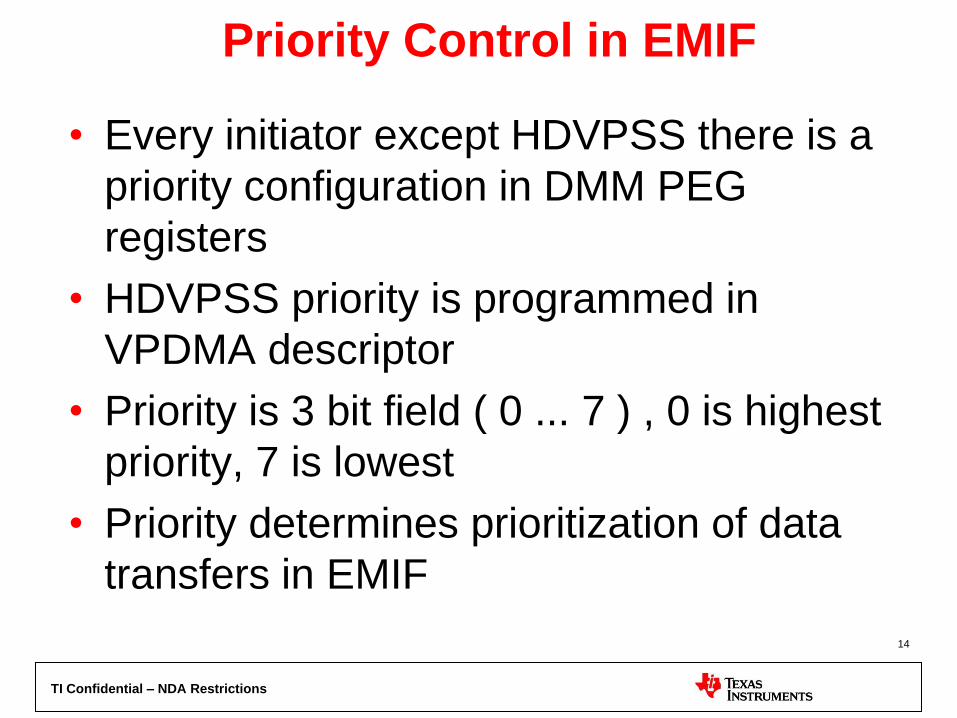
Priority Control in EMIF
• Every initiator except HDVPSS there is a
priority configuration in DMM PEG
registers
• HDVPSS priority is programmed in
VPDMA descriptor
• Priority is 3 bit field ( 0 ... 7 ) , 0 is highest
priority, 7 is lowest
• Priority determines prioritization of data
transfers in EMIF
14
TI Confidential – NDA Restrictions
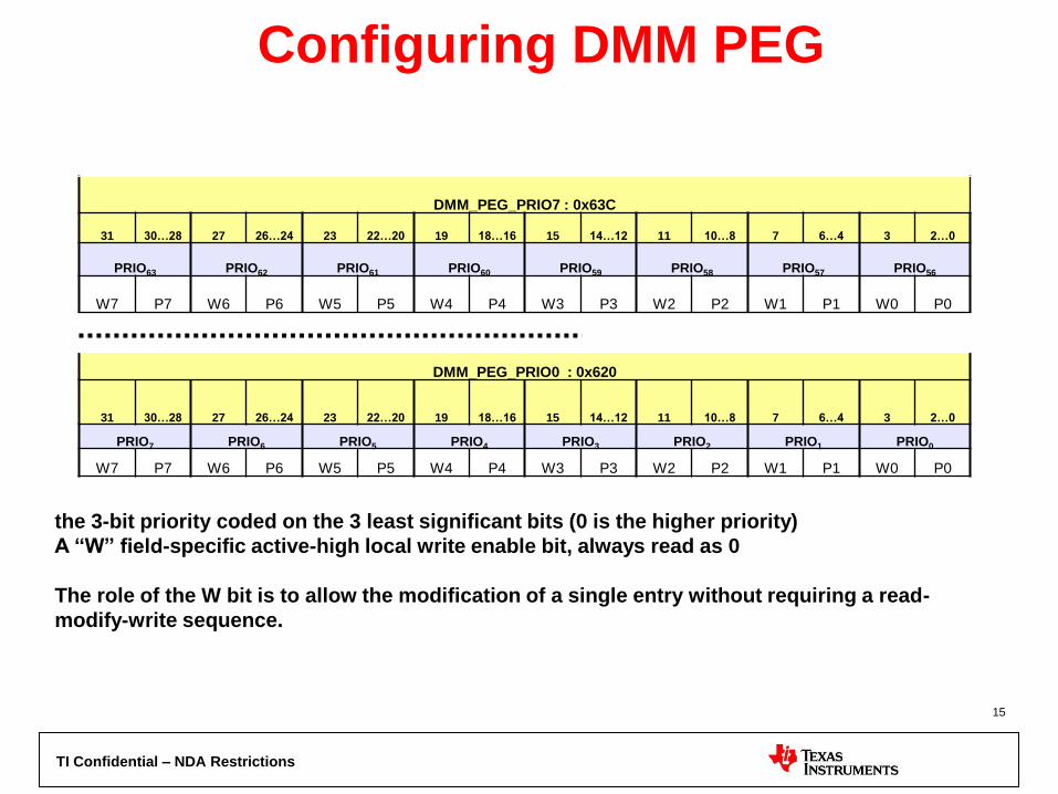
Configuring DMM PEG
DMM_PEG_PRIO0 : 0x620
31 30…28 27 26…24 23 22…20 19 18…16 15 14…12 11 10…8 7 6…4 3 2…0
PRIO7 PRIO6 PRIO5 PRIO4 PRIO3 PRIO2 PRIO1 PRIO0
W7 P7 W6 P6 W5 P5 W4 P4 W3 P3 W2 P2 W1 P1 W0 P0
DMM_PEG_PRIO7 : 0x63C
31 30…28 27 26…24 23 22…20 19 18…16 15 14…12 11 10…8 7 6…4 3 2…0
PRIO63 PRIO62 PRIO61 PRIO60 PRIO59 PRIO58 PRIO57 PRIO56
W7 P7 W6 P6 W5 P5 W4 P4 W3 P3 W2 P2 W1 P1 W0 P0
the 3-bit priority coded on the 3 least significant bits (0 is the higher priority)
A “W” field-specific active-high local write enable bit, always read as 0
The role of the W bit is to allow the modification of a single entry without requiring a read-
modify-write sequence.
15

TI Confidential – NDA Restrictions
DMM PEG Registers Initiator Register Register Address Priority Field
CortexA8 DMM_PEG_PRIO0 0x4E00_0620 PRIO0
System MMU DMM_PEG_PRIO1 0x4E00_0624 PRIO10
Ducati DMM_PEG_PRIO1 0x4E00_0624 PRIO14
SATA1 DMM_PEG_PRIO2 0x4E00_0628 PRIO16
TPTC0 Read DMM_PEG_PRIO3 0x4E00_062C PRIO24
TPTC1 Read DMM_PEG_PRIO3 0x4E00_062C PRIO25
TPTC2 Read DMM_PEG_PRIO3 0x4E00_062C PRIO26
TPTC3 Read DMM_PEG_PRIO3 0x4E00_062C PRIO27
TPTC0 Write DMM_PEG_PRIO3 0x4E00_062C PRIO28
TPTC1 Write DMM_PEG_PRIO3 0x4E00_062C PRIO29
TPTC2 Write DMM_PEG_PRIO3 0x4E00_062C PRIO30
TPTC3 Write DMM_PEG_PRIO3 0x4E00_062C PRIO31
SGX530 DMM_PEG_PRIO4 0x4E00_0630 PRIO32
HDVICP0 DMM_PEG_PRIO5 0x4E00_0634 PRIO40
ISS DMM_PEG_PRIO5 0x4E00_0634 PRIO44
GMAC0 DMM_PEG_PRIO6 0x4E00_0638 PRIO48
USB DMA DMM_PEG_PRIO6 0x4E00_0638 PRIO52
USB QMGR DMM_PEG_PRIO6 0x4E00_0638 PRIO53
SATA0 DMM_PEG_PRIO7 0x4E00_063C PRIO57
PCIe DMM_PEG_PRIO7 0x4E00_063C PRIO58
Only in DM814x
Only in DM385
16
TI Confidential – NDA Restrictions
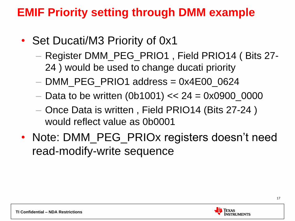
EMIF Priority setting through DMM example
• Set Ducati/M3 Priority of 0x1
– Register DMM_PEG_PRIO1 , Field PRIO14 ( Bits 27-
24 ) would be used to change ducati priority
– DMM_PEG_PRIO1 address = 0x4E00_0624
– Data to be written (0b1001) << 24 = 0x0900_0000
– Once Data is written , Field PRIO14 (Bits 27-24 )
would reflect value as 0b0001
• Note: DMM_PEG_PRIOx registers doesn’t need
read-modify-write sequence
17
TI Confidential – NDA Restrictions
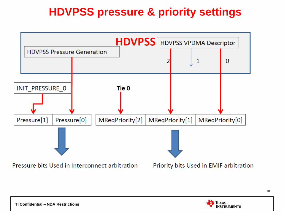
HDVPSS pressure & priority settings
18
TI Confidential – NDA Restrictions
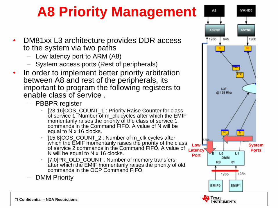
A8 Priority Management
• DM81xx L3 architecture provides DDR access to the system via two paths – Low latency port to ARM (A8)
– System access ports (Rest of peripherals)
• In order to implement better priority arbitration between A8 and rest of the peripherals, its important to program the following registers to enable class of service . – PBBPR register
• [23:16]COS_COUNT_1 : Priority Raise Counter for class of service 1. Number of m_clk cycles after which the EMIF momentarily raises the priority of the class of service 1 commands in the Command FIFO. A value of N will be equal to N x 16 clocks.
• [15:8]COS_COUNT_2 : Number of m_clk cycles after which the EMIF momentarily raises the priority of the class of service 2 commands in the Command FIFO. A value of N will be equal to N x 16 clocks.
• [7:0]PR_OLD_COUNT : Number of memory transfers after which the EMIF momentarily raises the priority of old commands in the OCP Command FIFO.
– DMM Priority
Low
Latency
Port
System
Ports
TI Confidential – NDA Restrictions
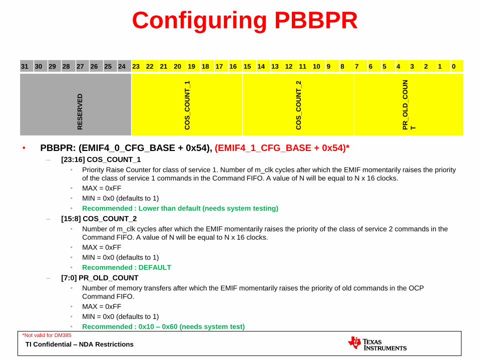
Configuring PBBPR
• PBBPR: (EMIF4_0_CFG_BASE + 0x54), (EMIF4_1_CFG_BASE + 0x54)*
– [23:16] COS_COUNT_1
• Priority Raise Counter for class of service 1. Number of m_clk cycles after which the EMIF momentarily raises the priority
of the class of service 1 commands in the Command FIFO. A value of N will be equal to N x 16 clocks.
• MAX = 0xFF
• MIN = 0x0 (defaults to 1)
• Recommended : Lower than default (needs system testing)
– [15:8] COS_COUNT_2
• Number of m_clk cycles after which the EMIF momentarily raises the priority of the class of service 2 commands in the
Command FIFO. A value of N will be equal to N x 16 clocks.
• MAX = 0xFF
• MIN = 0x0 (defaults to 1)
• Recommended : DEFAULT
– [7:0] PR_OLD_COUNT
• Number of memory transfers after which the EMIF momentarily raises the priority of old commands in the OCP
Command FIFO.
• MAX = 0xFF
• MIN = 0x0 (defaults to 1)
• Recommended : 0x10 – 0x60 (needs system test) *Not valid for DM385
31 30 29 28 27 26 25 24 23 22 21 20 19 18 17 16 15 14 13 12 11 10 9 8 7 6 5 4 3 2 1 0 R
ES
ER
VE
D
CO
S_C
OU
NT
_1
CO
S_C
OU
NT
_2
PR
_O
LD
_C
OU
N
T
TI Confidential – NDA Restrictions
ISS Based applications
- Priority Management
6/24/2012
TI Confidential – NDA Restrictions
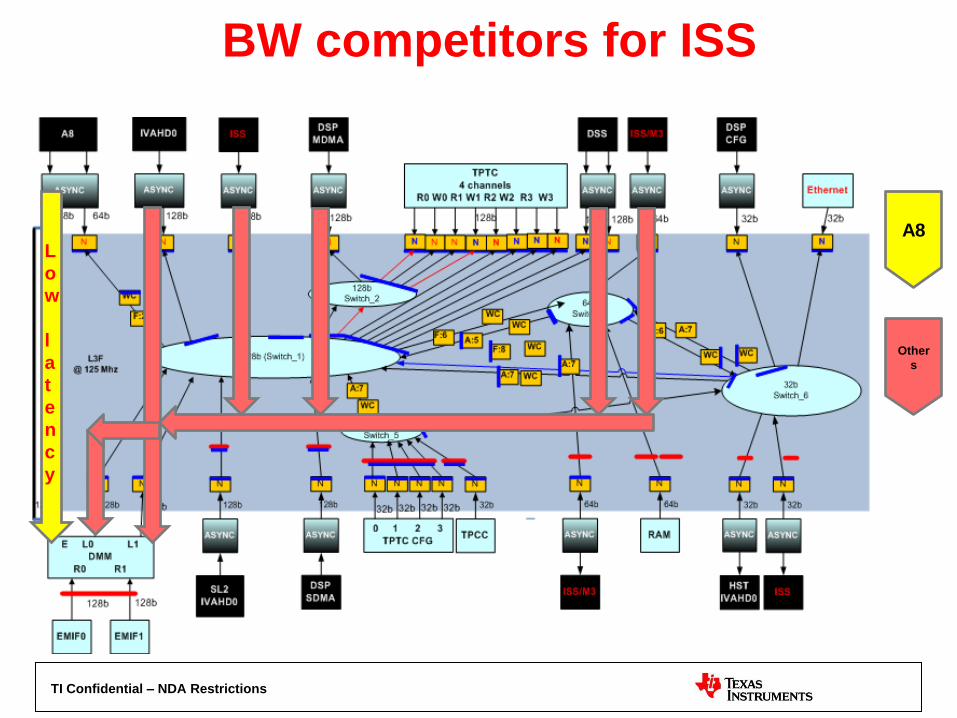
BW competitors for ISS
22
L
o
w
l
a
t
e
n
c
y
A8
Other
s

TI Confidential – NDA Restrictions
ISS priority control
• Following should be following in the given order: – ISS_BW_REGULATOR
• This should be the first knob to step up the ISS priority.
• Set PRESS_LOW and PRESS_HIGH to either ‘2’ or ‘3’ to setup static level 2 or level 3 pressure on ISS to DDR path.
– DMM PRIORITY • Configure DMM PEG priority to make ISS initiator as higher
priority (0 is highest) and other initiators (A8, IVA..etc) lower priority.
– ISS CLKDIV CONTROLs • Gradually decrease IPIPEIF_CLKDIV to lowest value which can
meet the usecase.
• Gradually decrease RSZ_CLKDIV from default value of 0xFFFF to reduce RSZ operation speed and thus RSZ DMA out rate. This should help RSZ OVF issues.

TI Confidential – NDA Restrictions
How to solve OVF issues? • Overflows in ISS are a result of insufficient availability of peak bandwidth
to ISS DMA. As a result it could result in RSZ, ISIF overflows or IPIPEIF
read under-run issues and cause performance losses.
• Tuning system for maximizing ISS bandwidth is typically a 2 step
process – first resolve peripheral priority to give ISS top priority and
second enable QOS on A8 so that it doesn’t deplete DMM/DDR
resource.
• Peripherals priority conflicts
– This covers priority arbitration conflicts between peripherals such as ISS and
other peripherals such as DSS, IVAHD, DSP..etc
– To configure ISS priority in such cases, following two priority schemes should
be enough:
• ISS BW REGULATOR
– Configure ISS BW regulator to prioritize ISS to DDR path with a priority
override of ‘2’ or ‘3’ (level). This is similar to setting the L3_PRIO
statically with the similar level.
• DMM PRIORITY
• ARM vs ISS priority conflicts
– In this scenario the conflict is between ISS, DSS..etc and ARM (A8) for DDR
priority arbitration. Since A8 has a low latency path to DDR regular
DMM_PRIORITY configuration scheme doesn’t work well. To configure ISS
priority in such cases please follow:
– BURST PRIO (PBBPR register)
• Configure COS_COUNT_1, COS_COUNT_2 and PR_OLD_COUNT
– DMM PRIORITY

TI Confidential – NDA Restrictions
Thank You
6/24/2012


![Index [ptgmedia.pearsoncmg.com]...EIGRP authentication, 101–102 bandwidth command, 103–104 bandwidth configuration, 102–104 bandwidth-percent command, 104 ip bandwidth-percent-eigrp](https://static.fdocuments.in/doc/165x107/5ed079ce95646c550611f388/index-eigrp-authentication-101a102-bandwidth-command-103a104-bandwidth.jpg)