Balun Project - Colby Collegepersonal.colby.edu/personal/t/trberger/pages/pdfs/ProjectBalun.pdfBalun...
11
Balun Project Tom Berger K1TRB February 14, 2012 This project builds a 4:1 and a choke balun suitable for high frequency (1.8 – 30MHz) use. With modest common mode currents these baluns are suitable for 1 kw. The boxes are weatherized for outdoor use. Pictures are also shown of smaller 100 watt balun using similar construction with a small balun core. Materials: 2.4 inch diameter cores 2 22 inch lengths of 14-2 Type NM wire cable (Romex) 2 2.4 inch diameter 31 material cores (Fair Rite 2631803802) 1 or 2 electrical outlet boxes (Home Dept B118A, depth is important) 8 x 10 inch polycarbonate sheet of clear plastic (Home Depot 31-GE-XL-1) Female coax fittings for boxes, up to 2 fittings per box The following for each binding post pair on a box end (e.g. ladder line or antenna connection): (all brass if the box is to be outside) 2 8-32 x 1” screws 8 washers 4 nuts 2 ground lugs (I am not worried if the following rust, so I used steel) 2 6 x ¾” sheet metal screws to hold the box cover on (for each box) 2 6-32 x ¾” to hold a clamp on the box top (for each clamp) 2 6-32 nuts Black plastic electrical tape Silicon caulk to seal boxes. Schematics: o Choke Balun At the right is the schematic (A) for the choke balun. It has 7 bifilar turns on a 2631803802 core. One turn is counted as one pass through the hole in the core. The balun is symmetrical so the two ends
Transcript of Balun Project - Colby Collegepersonal.colby.edu/personal/t/trberger/pages/pdfs/ProjectBalun.pdfBalun...

Balun ProjectTom Berger K1TRB
February 14, 2012
This project builds a 4:1 and a choke balun suitable for high frequency (1.8 – 30MHz) use. With modest common mode currents these baluns are suitable for 1 kw. The boxes are weatherized for outdoor use. Pictures are also shown of smaller 100 watt balun using similar construction with a small balun core.
Materials:
2.4 inch diameter cores
2 22 inch lengths of 14-2 Type NM wire cable (Romex)2 2.4 inch diameter 31 material cores (Fair Rite 2631803802)1 or 2 electrical outlet boxes (Home Dept B118A, depth is important)8 x 10 inch polycarbonate sheet of clear plastic (Home Depot 31-GE-XL-1)Female coax fittings for boxes, up to 2 fittings per boxThe following for each binding post pair on a box end (e.g. ladder line or antenna connection):(all brass if the box is to be outside)2 8-32 x 1” screws 8 washers4 nuts2 ground lugs
(I am not worried if the following rust, so I used steel)2 6 x ¾” sheet metal screws to hold the box cover on (for each box)
2 6-32 x ¾” to hold a clamp on the box top (for each clamp)2 6-32 nuts
Black plastic electrical tapeSilicon caulk to seal boxes.
Schematics:
o Choke Balun
At the right is the schematic (A) for the choke balun. It has 7 bifilar turns on a 2631803802 core. One turn is counted as one pass through the hole in the core. The balun is symmetrical so the two ends
may be switched. B and D are not connected together. This balun is good for connecting a balanced to an unbalanced line. This balun will not lower a high swr but by choking common mode currents it smooths the transition between lines of two different impedances.
This is often called a Guanella or Current Balun.
o 4:1 Balun
At the right is a schematic (B) of the 4:1 balun. It has 7 bifilar turns on a 2631803802 core. One turn is counted as one pass through the hole in the core. Dots denote one end of a winding. The balun steps up or down the impedance so the up side is called High and the down side Low. This balun can connect a balanced to an unbalanced line if the higher impedance is the balanced line. The impedance at the high side E F is 4 times the impedance at the low side G H. H can be left ungrounded so that G and H can be connected to a balanced line. In this balanced case, E is grounded and F is connected to the center conductor of the coax.
This is often called a Ruthroff or Voltage balun. It has very little choking capability.
o 4:1 Choke Balun
The 4:1 balun is not a very good choke. However, it is easy to join a choke balun with a 4:1 balun. (There are direct 4:1 choke baluns that require three cores but are not part of this project.)
The choke balun is connected to the low side of the 4:1 balun. The common mode rejection impedance of the choke balun is R. The common mode voltage is E so that the power dissipated by R is E2/R. If we connected the choke balun on the hight side the voltage would be 2E multiplying the power by 2. Thus the low side is probably the wiser connection.

In schematic (C), the low impedance is connected to A and B and the high impedance to G and H. If both lines are unbalanced, B and H are connected to the “ground” side of each line. The do not connect these two “grounds.” If the high side load is balanced then A is connected to the shield and B goes to the center conductor of the coax. If the low side is balanced, then H is connected to the shield and G is connected to the center conductor of the coax.
Balun Building
Instructions:
1. Cut a 22 inch length of Type NM 14-2 house wiring cable (sometimes called Romex). Do not buy this. Surely scraps can be had by asking hams or handy friends.
2. Lay 22 inch of cable on a flat work surface. Using a box cutter slit along the whole length of the cable. Do not cut deeply, you will cut the wire insulation. It is only necessary to score the surface. Peel away the plastic insulation and recover a black and a white 22 inch length of wire. Save the bare ground wire.
3. With a felt tip pen, beginning at 2 ½ inches, make 18 marks on the white wire at 1 inch intervals. See the picture.
4. Cut 9 1 inch lengths of black vinyl electrical tape. Cut each piece lengthwise to make 18 pieces of tape. See the picture showing some cut and other uncut pieces.
5. Lay the black and white wires side by side. Even up the ends. Wrap tape around the wires to bundle them at each of the 18 marks on the white wire. See the picture (with 2 turns already inserted through the core).
6. On a small piece of tape write “31” and put it on the core. Without measurements, it is not possible to distinguish a mix 43 core from a mix 31 core.
7. Wind 7 turns on the core. Begin with 2 inches of wire sticking out of the core. One pass through the core is 1 turn. Do not break the core! Grip it between a thumb and finger at the winding point so the core does not twist and break. Spread the
turns evenly around the core. Two turns is about ¼ around the core and 3 turns is close to halfway. See the picture of a fully wound core.
8. Remove any extra tape ties on wire at the ends.
9. Strip insulation off the wire back to within about ½ in of he core. See the picture.
10. Wind two cores this way: One for a choke balun and one for the 4:1 balun. The result is shown in schematic (A) and in the picture.
11. You may wish to label the wires of one balun as A,B,C,D (see schematic (A)), and E,F,G,H (see schematic (B)) with small pieces of masking tape. Put the tape on the insulation as close to the core as feasible. These pieces of tape will help in wiring the baluns together or into a box.
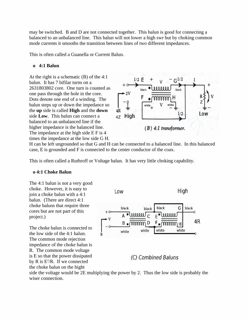
The 4:1 Balun
1. Connect one winding end black wire to the other winding end white wire as shown in the picture.
2. Solder the joint and tin all wires coming out of the cores. See the picture. Also look at the schematic (B) of the 4:1 balun.
3. The choke and 4:1 balun cores are now complete. The remaining instructions show how to build box up the baluns.
Balun Boxes:
Box Building Instructions ((A) Choke Balun):
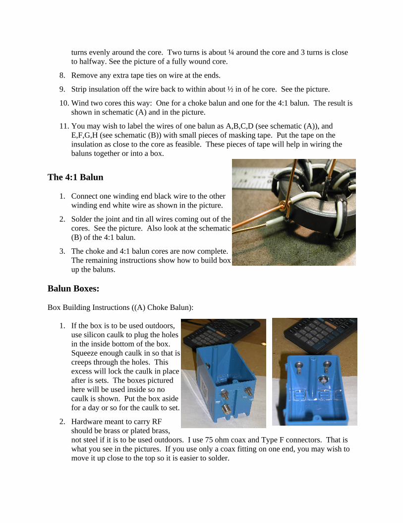
1. If the box is to be used outdoors, use silicon caulk to plug the holes in the inside bottom of the box. Squeeze enough caulk in so that is creeps through the holes. This excess will lock the caulk in place after is sets. The boxes pictured here will be used inside so no caulk is shown. Put the box aside for a day or so for the caulk to set.
2. Hardware meant to carry RF should be brass or plated brass, not steel if it is to be used outdoors. I use 75 ohm coax and Type F connectors. That is what you see in the pictures. If you use only a coax fitting on one end, you may wish to move it up close to the top so it is easier to solder.

I use two screws to create binding posts on the box end that will connect to an antenna or ladder line. The choke balun shown in these instructions includes both binding posts and a coax fitting since it will be used in a variety of ways.
The binding posts are created as follows. Put a ground lug on a 1” brass screw followed by a washer. Pass the screw through the box then add a washer and a nut. Tighten the nut so the ground lug is point upward toward the box opening. Then add two washers and a nut to form the locking part of the binding post. Wire or lugs are clamped between these final two washers. That is, the antenna wire or ladder line wire is held between the two final washers.
3. Mark the box and install the binding post screws in 3/16” holes and coax fittings. Use the pictures and diagram as a reference. If you will be using only a fitting, place it closer to the top of the box since soldering to the fitting deep in the box is a challenge. The pictured box has a Type F fitting on both ends and binding posts on one end.
4. You can used the pigtails left on the wound cores or you can add stubs of wire to the box before installing the balun in the box. Stubs can use the ground wire you removed from the wiring cable. I used 20 awg doorbell wire. It will carry the 1.5 amps flowing when 1000 watts passes through the balun. For 100 watts it is far more than ample. You might wish to stay with the 14 awg pigtails of the balun if you wish to push 1500 watts PEP through the balun. The bigger the wire, the lower the loss, even though this loss is very small.
5. The pictures show how I wired stubs to be connected to the balun pigtails.
6. Cut a top for the box out of clear plastic (Lexan). The plastic should overhang the edges of the box so that silicon caulk can be applied. The basic box cover is 2 ¾ inches by 4 ¼ inches. If binding posts are used to hold ladder line 1 ½ inches additional are needed. If binding posts are used on both ends then the overhang may be needed on both ends. I recommend one overhang even without binding posts so that you can hang the box from something. So: 5 ¾ x 2 ¾ with one overhang and 7 ¼ x 2 ¾ with two overhangs. For each overhang, cut a piece of plastic ¾ x 2 ¾ to serve as a clamp on the overhang. See the picture.

7. Placing the plastic on top of the box you can mark the two holes for screws into the box. (Shown 3 ¼ apart on the diagram.) Mark the hole with an awl. Screws will be 6-32 so holes should be drilled 5/32 inch in diameter. Mark and drill the overhang. Use the holes of the overhang to mark the clamp plastic with an awl. Drill the clamp plastic. I used ½ inch #6 sheet metal screws anchoring the top to the box.
8. Mount the balun in the case. The picture shows a choke balun mounted. This picture is large so you can see the method of soldering. The box wire was laid against the balun wire for about 1 inch and soldered along the full length. Lead is not a great conductor so this decreases resistance and also the strength of the joint. You could use a Western Union splice but that is both difficult and overkill. If you feel the balun needs more rigid mounting in the box, stuff styrofoam peanuts around the balun to hold it securely. I’m happy with just the wires.
9. Install the top and the clamp. I put a strip of rubberized electricians tape on the clamp to hold the ladder line securely. That strip is not shown since it should be applied as the box is installed in its final location.
10. If the box is to go outside, seal all around the overhang of the top with silicon caulk. The coaxial fittings are probably not water tight (unless you used Type N) so pay special care to weather sealing the connections after the box is installed.
Box Building Instructions ((B) 4:1 Balun):
1. Follow steps 1-10 of the instructions of the choke balun except refer to the pictures here showing the balun in the box. At the right is a picture of the balun, drilled box, and drilled top plus clamp.

2. The the picture shows the the balun in the box with the wires dressed to fit and soldered. The white wire goes to both ends of the box so a piece of wire is spliced on to the white wire pigtail. The tap needs only one wire so the other is trimmed. The black wire goes to only one end of the box. Since I do not need a permanently installed 4:1 balun, I put binding posts and coax fittings on both ends so I could connect the box either as a step up or step down transformer.
Box Building Instructions ((C) 4:1 Choke Balun):
I did not build this balun, but I have taken a couple pictures showing how it might be wired and how to fit it in the box. Putting both baluns in the same box allows a small amount of coupling between the two baluns. I have not measured the impact of this coupling on the functioning of the balun, but I believe it is small.
1. The first picture shows the choke and 4:1 balun next to each other ready to wire up. Note the piece of plastic separating the two baluns. This is cut to space the baluns apart, but also to fit easily into the box. Use the box top plastic for this spacer.
2. Notice the two wires at the tap on the front 4:1 balun in the center front. There is a black wire on the back choke balun that crosses over to the tap. This crossing wire is soldered to the tap. The wires are C, E, and H from schematics (A) and (B) which are shown connected in schematic (C).
3. The white wire (paired with the black wire of step 2) is dressed to the right beside the white wire coming from the 4:1 balun: D and F in the schematics.
4. The other end wires A and B of the choke balun are dressed to the left.

5. The remaining black wire G of the 4:1 balun is dressed to the right.
6. Look now at the picture of the pair of baluns set in the box. Wires A and B are dressed
left. They connect at the left end of the box.
7. The tap (C, E, and H) in the center should be soldered and trimmed.
8. The two white wires (D and F) dressed right are soldered together and form the shield connection at this end of the box.
9. The center connection at this end of the box is the black wire G dressed right. See schematic (C) and the picture.
10. Which wire (A or B) on the left is the shield wire depends on how the choke is used. Wire A is the shield if the other end connects to a balanced line. Wire A is the center conductor if the other end is an unbalanced line. For a multi-purpose box, connect A to the center conductor and B to the shield of the coax.
11. With these observations, follow steps 1-10 for building the choke balun box.
Smaller Baluns:
By using the 1” diameter 2631102002 core, smaller baluns can be made that will operate at 100 watts. They are wound with 20 awg doorbell wire and mounted in a smaller B108R box. Since these are outlet boxes, the top is identical to the one already described. There is very little room on the box end so binding posts or a coax fitting may be used, but not both. This balun actually performs slightly better than its larger counterpart.

The choke and 4:1 baluns of this size are also wound with 7 bifilar turns. In this case the thermostat wire is twisted to make a twisted pair so that no tape is needed to hold the two wires together. The pictures shows the top and bottom view of a finished choke balun. I have one of these boxes outdoors between the ladder line and coax on my loop antenna. One end of the box has binding posts and the other a type F fitting for RG6 coax. The box still looks fine after two winters of service.
Balun Uses:
Wherever you either measure or believe common mode currents are flowing on a transmission line and you don’t want those currents, a choke balun is useful. If the impedance on the line is greater than 4 times the coaxial line impedance then a 4:1 impedance step down might be useful. (Greater than 200 ohms for 50 ohm coax or greater than 300 ohms for 75 ohm coax.) When the impedance of the line is less than ¼ the coaxial line then a 1:4 step up transformer may help. (Less than 12.5 ohms for 50 ohm coax or 19 ohms for 75 ohm coax.)
Ladder line is frequently used as transmission line or as an impedance transformer since it is so low loss. A choke balun can be placed between the coax and the ladder line to limit common mode currents in the coax. A common mode choke is a good transition from a balanced to an unbalanced line (e.g. joining 75 ohm coax to the center of a resonant dipole or joining ladder line to coax).
If the two baluns are to be joined in one box as shown in schematic (C), then the choke balun should be between the tap E and one side F of the 4:1 balun since this is the low impedance side of the 4:1 balun as shown in schematic (C). On the other end of the choke balun, wire A usually connects to the center conductor and wire B to the shield of the coax. However, there is a transformer effect so the combination may perform better with A and B reversed. Experiment to determine the best connection.
Performance of the Baluns:
In the cases shown below, the Mix 31 toroids outperform the more popular Mix 43 baluns, i.e. the graphs look better when measured with an N2PK VNA.
1. Choke impedance of the Choke Balun
The choke imposes a choking impedance greater than 1000 ohms over the whole high frequency range. The maximum is greater than 2000 ohms. For comparison, a 10 turn coaxial balun wound 8 inches in diameter supplies only about 300 ohms on 160 meters.

The Choking Z graph shows both the 2.4” choke balun of this project and the 1” choke balun illustrated above. The 1” core outperforms the 2.4” core. However, the power dissipation of the smaller core is much less. The smaller core would be more comparable at about 5 turns instead of 7.
I am not sure how much power the 2.4” core will dissipate without overheating, but I believe it is somewhere around 10 watts. What common mode current will dissipate 10 watts in 1000 ohms? Since P = I2 R, the current would be 0.1 amps. To generate 10 watts there would be 100 volts across the choke. At 1500 watts PEP, the rms voltage on a 50 ohm line is 194 volts. This is only 2 times the 100 volt common mode voltage developed across the core. Wow! If this situation occurs, it’s time to fix the antenna and the line, not to worry about the core.
2. Core mismatch at 50 ohms
Imagine the core is connected at both ends to a perfectly matched 50 ohm line. The twin wires wound on the core are a transmission line of about 130 ohms impedance. Even though the winding is less than 22 inches of transmission line, this causes a mismatch. The core itself is not a perfect choke so the core also introduces a mismatch.
Over the high frequency range, the SWR is less than 2:1. This is very good. We can consider a line matched if the SWR is less then 2:1. Notice than at lower frequencies, the match is close to 1:1. This change occurs because 22 inches is much closer to 10 meters than it is to 160 meters. That is, the transforming effect of the 130 ohm winding transmission line is larger at 10m than at 160m.
Our lines are almost never matched. More often than not, the antenna side impedance of the balun is 100 ohms or more. In that case, the transforming effect of the balun is to improve, not degrade, the match. Therefore, swr measurements should be treated with some circumspection.
3. The 4:1 impedance ratio
The 4:1 balun should step 50 ohms up to 200 ohms. (It should step 75 ohms up to 300 ohms.) The step up from 50 ohms varies from 190 ohms at 160m to 210 ohms at 10m. This is not bad at all.

Again the bifilar winding is a transmission line 22 inches long of about 130 ohms. Therefore, it is also transforming impedance in a way that increases with frequency. Thus, as for SWR, the impedance is increasing with frequency.