BALLAST WATER MANAGEMENT PLAN€¦ · This BWM Plan has been written by use of a DNV template...
25
This BWM Plan has been written by use of a DNV template (BWM-07) BALLAST WATER MANAGEMENT PLAN Vessel name: <NAME OF VESSEL> IMO number: <IMO NO> DNV GL ID: <DNV GL ID> Document reference: <doc. ref.> Document date: <doc. date> Created by: <created by>
Transcript of BALLAST WATER MANAGEMENT PLAN€¦ · This BWM Plan has been written by use of a DNV template...

This BWM Plan has been written by use of a DNV template (BWM-07)
BALLAST WATER MANAGEMENT PLAN
Vessel name: <NAME OF VESSEL>
IMO number: <IMO NO>
DNV GL ID: <DNV GL ID>
Document reference: <doc. ref.>
Document date: <doc. date>
Created by: <created by>
This BWM Plan has been written by use of a DNV template (BWM-07)
******* Please delete the text between the red lines in the vessel specific Plan *******
Guidance Note This is a guidance note for the author/editor of this Ballast Water Management Plan (BWMP).
How to use the template The template is designed to make the preparation of the BWMP as easy as possible. We have
included as much standard text as possible, and limited the scope of the plan to the minimum.
This plan shall cover all requirements for developing a BWMP in resolution MEPC.127(53).
The MEPC.127(53) G4 of the convention is a guide on structure and content on what to include in
the BWMP.
1. Use the template to create your vessel specific BWMP. Use your own stationary / logos /
company name etc. as preferred.
2. Submit the BWMP in electronic format (pdf format) for review. Please use the following
email address [email protected] and ensure that the vessel’s DNV / GL ID. no is given. The
BWMP shall be submitted in one file only, including appendices.
3. Appendices with scanned/copied drawings shall include the drawings’ title field. This will
serve as verification of drawing id and revision number, and ensures that we are handling
the same drawings.
4. DNV GL can approve the BWMP on paper or electronically. For paper approval, please
ensure a relevant number of copies are submitted (taking into account that 1 copy will be
kept for DNV GL files and 1 originally stamped copy is required to be kept on board the
vessel).
5. A paper copy of an electronically approved BWMP can be sent upon request.
6. Note that BWMP are approved on a vessel by vessel basis.
7. In MEPC 207(62) IMO has set out recommendations for a Biofouling Management Plan and
Record Book, fouling control coating installation and maintenance, in-water inspection and
cleaning, considerations at design and construction. The Biofouling Management Plan is not
mandatory for international voyages yet. For calls to US ports USCG applies MEPC 207
since 21 June 2012. The Biofouling Management Plan is subject to VGP and can be included
in or referred to in the BWM Plan. A template for a biofouling management plan is available
on DNV GL homepage http://www.dnvgl.com/BWM/
Fields shaded in yellow: Requires input and must be replaced.
Fields shaded in grey: Comments from DNV GL that must be deleted.
Blank text: Required text that can be used without any changes.
******* Please delete the text between the red lines in the vessel specific Plan *******

This BWM Plan has been written by use of a DNV template (BWM-07)
REVISION HISTORY
Rev. No. Date Reason for Issue Prepared by
[Name and company name]
Verified by Approved by

This BWM Plan has been written by use of a DNV template (BWM-07)
CONTENTS
INTRODUCTION .......................................................................................................................... V
VESSEL PARTICULARS ................................................................................................................ VI
PURPOSE................................................................................................................................... VI
1 DESCRIPTION OF THE BALLAST SYSTEM ........................................................................... 1
2 BALLAST WATER MANAGEMENT OPERATION ...................................................................... 2
3 BALLAST WATER EXCHANGE <REMOVE IF NOT APPLICABLE> ............................................. 3
4 BALLAST WATER TREATMENT <REMOVE IF NOT APPLICABLE> ............................................ 8
5 PRECAUTIONARY PRACTICES .......................................................................................... 12
6 SEDIMENT MANAGEMENT ............................................................................................... 13
7 BALLAST WATER SAMPLING ........................................................................................... 14
8 METHODS OF COMMUNICATION ...................................................................................... 16
9 DUTIES OF THE BALLAST WATER MANAGEMENT OFFICER .................................................. 17
10 CREW TRAINING AND FAMILIARIZATION ......................................................................... 18
11 RECORDING REQUIREMENTS .......................................................................................... 19
APPENDICES .............................................................................................................................. 19

This BWM Plan has been written by use of a DNV template (BWM-07)
INTRODUCTION
Ballast water is essential to control trim, list, draught, stability, or stresses of the vessel. However,
ballast water may contain aquatic organisms or pathogens which, if introduced into the sea
including estuaries, or into fresh water courses, may create hazards to the environment, human
health, property or resources, impair biological diversity or interfere with other legitimate uses of
such areas.
This plan is written in accordance with the requirements of Regulation B-1 of the International
Convention for the Control and Management of Vessels' Ballast Water and Sediments, 2004 (the
Convention) and the associated Guidelines.
The purpose of the plan is to meet the requirements for the control and management of vessel’s
ballast water and sediments in accordance with the Guidelines for Ballast Water Management and
the Development of Ballast Water Management Plans (G4) resolution MEPC.127(53). It provides
standard operational guidance for the planning and management of vessels' ballast water and
sediments and describes safe procedures to be followed.
The selection of appropriate methods of Ballast Water Management should take into account the
need to ensure that Ballast Water Management practices used to comply with the Convention do
not cause greater harm to the environment, human health, property or resources of any States and
the safety of vessels, than they prevent.
This plan has been approved by the <Administration or DNV GL> and no alteration or revision shall
be made to any part of it without the prior approval of <Administration or DNV GL>.
Existing approved plan for ballast water exchange can also be used for this vessel, < add reference
to document number and approval letter> <Remove the complete paragraph if only treatment is
applicable> <Remove the exchange methods that are not applicable>
This plan may be inspected on request by an authorized authority.

This BWM Plan has been written by use of a DNV template (BWM-07)
VESSEL PARTICULARS
Vessel name xxx
IMO number xxx
Flag xxx
Port of registry xxx
Vessel type xxx
Dimensions
Gross Tonnage xxx
Length b.p xxx
Beam xxx
Deepest ballast draughts
(normal/heavy weather)
xxx
Total ballast water
capacity
xxx
Designated ballast water
management officer (rank
of officer)
xxx
Main ballast water management method(s): <Remove the methods that are not applicable>
D-1 (ballast water exchange): <Sequential, flow-through, dilution>
D-2 (ballast water treatment): <example: UV + filter>
PURPOSE
The ballast water management plan aims to assist governments, appropriate authorities, vessels'
Masters, operators, owners, port authorities as well as other interested parties, in preventing,
minimising and ultimately eliminating the risk of introducing harmful aquatic organisms and
pathogens from vessels' ballast water and associated sediments while protecting vessels' safety.
Good record keeping is critical to the success of a sound ballast water management program. The
appointed ballast water management officer is responsible for ensuring the maintenance of
appropriate records and that the ballast water management and treatment procedures are followed
and recorded. <Include reference to ballast water form and record book>
It is the owners/managers or Master's responsibility to regularly review the plan and ensure that
the information contained therein is accurate and updated.

Page 1 of 25
This BWM Plan has been written by use of a DNV template (BWM-06)
1 DESCRIPTION OF THE BALLAST SYSTEM
Ballast water is essential to control trim, list, draught, stability or stresses of the vessel.
The vessel’s ballast system consists of the following:
1.1 Overview of BWM methods applied <Remove if not applicable>
BW Tank # BW Exchange BW Treatment
Sequential Method
Flow-Through Method
Dilution Method
FPT x x
No.1 Side Tank x x x
1.2 Ballast tanks
Tank # Location
(frames)
Capacity [m3] Pumps
available
max FSM
1.3 Emergency / Heavy weather compartments <Remove if not
applicable>
Tank # Location
(frames)
Capacity [m3] Pumps available
1.4 Pump data
Pump # Rated capacity
[m3/hr]
Type Location

Page 2 of 25
This BWM Plan has been written by use of a DNV template (BWM-06)
2 BALLAST WATER MANAGEMENT OPERATION
2.1 General
Ballast Water Management System (BWMS) means any system which processes ballast water such that
it meets or exceeds the ballast water performance standard in regulation D-2. The BWMS includes ballast
water treatment equipment, all associated control equipment, monitoring equipment and sampling
facilities.
BWMS means equipment which mechanically, physically, chemically, or biologically processes, either
singularly or in combination, to remove, render harmless, or avoid the uptake or discharge of harmful
aquatic organisms and pathogens within ballast water and sediments. Ballast water treatment equipment
may operate at the uptake or discharge of ballast water, during the voyage, or at a combination of these
events.
Ballast water exchange can also be used for this vessel, but only to meet the standard described in
regulation D-1. The applicable methods are: sequential method, flow through method and dilution
method or a combination of those. <Remove the complete paragraph if only treatment is applicable>
<Remove the exchange methods that are not applicable>
Ballast water exchange will be phased out as an acceptable method for complying with the Convention,
depending on ballast water capacity and date for renewal survey of the vessel. Therefore ballast water
treatment will be the only remaining option for complying with the Convention. <Remove the complete
paragraph if only treatment is applicable>
During normal conditions the treatment system is to be used for ballast water operations, however it is
possible to bypass this and then ballast exchange can be conducted. <Remove the complete paragraph if
only treatment is applicable> It is the responsibility of the ballast water management officer to decide
which method is to be used (e.g. in port states where discharge of treated ballast water is not a
requirement.)
It is the Master’s responsibility to control the safety of the vessel at all times. This includes evaluation of
stability and longitudinal strength throughout the sequential exchange sequence.
The sequence included in this document is only one example of an acceptable sequence for one specific
loading condition. <Remove the complete paragraph if only treatment is applicable> <Remove the
exchange methods that are not applicable>
It must be ensured that the ballast water treatment system installed is approved in accordance with
Regulation D-3 of the Convention. All systems (type) approved by any IACS Class society and physically
inspected by Class’ surveyor after installation should fulfil this requirement.
The system should only be operated in accordance with the system design criteria and manufacturer's
operational and maintenance instructions. When the system encounters malfunctions or failure, these
are to be recorded in the ballast water record book.

Page 3 of 25
This BWM Plan has been written by use of a DNV template (BWM-06)
3 BALLAST WATER EXCHANGE <REMOVE IF NOT APPLICABLE> There are three methods of ballast water exchange which have been evaluated and accepted by IMO.
The three methods are the sequential method, the flow-through method and the dilution method. The
flow-through method and the dilution method are considered as "pump through" methods.
Regulation B-4 of the Convention requires that vessels shall conduct ballast water exchange:
• at least 200 nautical miles from the nearest land and in water at least 200 metres in depth; if
this is not possible
• at least 50 nautical miles from the nearest land and in water at least 200 metres in depth; or
• in areas designated by the Port State.
All local and/or national regulations should be taken into consideration as they may specify other depths
and distances from land.
It is the Master’s responsibility to control the safety of the vessel at all times. This includes evaluation of
stability and longitudinal strength throughout the sequential exchange sequence.
The sequence included in this document is only one example of an acceptable sequence for one specific
loading condition. <Remove the complete paragraph if sequential method is not applicable>
A vessel shall not be required to deviate from its intended voyage or delay the voyage in order to comply
with any particular requirement as stated above.
The voyage should be planned taking into account when ballast water exchange in accordance with the
above criteria can be carried out.
Because of the possibility that partially exchange may encourage re-growth of organisms, ballast water
exchange should only be commenced in any tank if there is sufficient time to complete the exchange to
comply with the standard in Regulation D-1 and the vessel can comply with the distance from land and
minimum water depth criteria in Regulation B-4. As many complete tanks should be exchanged to the
standard in Regulation D-1 as the time allows, if for any tank the standard in Regulation D-1 cannot be
fully met the exchange should not be commenced for that tank.
In addition, if the master reasonably decides that an exchange would threaten the safety or stability of
the vessel, its crew or passengers because of adverse weather, vessel design or stress, equipment
failure, or any other extraordinary condition he is not required to comply with above requirements.
When a vessel is required to conduct ballast water exchange and does not do so in accordance with
these requirements, the reasons shall be entered in the ballast water record book.
The applied ballast water exchange methods for this vessel are the following:
3.1 Sequential method <Remove if not applicable>
3.1.1 General The sequential method is a process by which a ballast tank intended for the carriage of ballast water is
first emptied and then refilled with replacement ballast water to achieve at least a 95 per cent volumetric
exchange.
All of the ballast water in each tank should be discharged until suction of the pumps is lost and stripping
pumps or eductors should be used if possible, to avoid a situation where organisms are left in the bottom
of the tank, the tank is then refilled with new water rich in oxygen which might allow the re-emergence
of new organisms.

Page 4 of 25
This BWM Plan has been written by use of a DNV template (BWM-06)
A detailed step by step operational description of the ballast exchange sequence used should be
consulted prior, during and after the exchange in addition to the safety considerations addressed below.
At the same time ballast water management officer should take account of vessel's position in relation to
the land, navigational hazards, vessel traffic in the vicinity, current and forecast weather, machinery
performance and degree of crew fatigue, before deciding to proceed to the next pair of steps. If any
factors are considered unfavourable the ballast exchange should be suspended or halted.
When planning a complete ballast water exchange sequence, the following can be used as guidance:
• the sequence is to be divided into steps;
• each step represents emptying or (re)filling one tank or pair of tanks and is to be run as any
other loading condition on the loading computer. Maximum free surface moment for the tanks
being emptied or refilled must be taken into consideration;
• amount of consumables to be kept constant;
• if necessary, some tanks may be emptied first and remain empty during completion of the
exchange of other tanks, and then refilled;
• heel should preferably remain < 2 degrees in all steps and never exceed 5 degrees; and
• execution may be halted at any time for a shorter or longer period
The results (printouts) from the loading computer to be summarised in a table clearly showing for each
step:
• Degree of fill for each tank. Symbols used:
- F indicates full;
- S indicates slack;
- * indicates empty; and
- C indicates changed.
• GM or VCG (FSM corrected) in meters, to ensure compliance with the stability criteria;
• draft forward and aft (+trim) in metres;
• max BM (hog or sag) as percentage of the max allowable (0.3L - 0.7L);
• max SF as percentage of the max allowable;
• length of invisible zone ahead of the bow;
• propeller immersion ratio (100% is fully immersed);
• time estimated, based on specific pump capacity.
3.1.2 Safety considerations for the sequential method Related to weather:
• Rough sea: Bottom slamming in the fore vessel, causing structural damage. This is
dependent on the draught forward, and the vessel heading. If slamming is experienced
during emptying of some of the tanks, it is possible to stop/reduce this by temporarily altering
the vessel’s heading or reducing the speed.
Sloshing in tanks, causing deflection/damage to internal tank structure.
• Strong wind: Depends upon the wind direction. If the ballast water exchange involves steps
which cause that the vessel can not keep upright condition all the time or reduced GM, side wind
may contribute to heel/roll. Static heel should be max. Two (2) degrees, preferably.
• Low temperatures in which icing in the ballast tank air pipes may occur. Clogging, ice-
plugs or malfunctioning of air vent heads may lead to structural damage to tanks. • Crew safety, if ballast water exchange requires manual deck operations.
Related to internal loads:
• Exceeding permissible maximum allowable limits with respect to longitudinal strength (shear
force and bending and torsional moment). This could cause damage even in good weather
conditions, and the stresses increases with increasing waves. All new conditions not
previous calculated should be checked on the vessels loading computer, for each step in the
exchange sequence.
• Loss of stability. As emptying of ballast tanks often results in free surface effects and
increased VCG, there should always be included a sufficient safety margin in the initial condition.

Page 5 of 25
This BWM Plan has been written by use of a DNV template (BWM-06)
• The combination of full ballast holds and empty topside and/or hopper side tanks may induce
dynamic loads which could exceed the capability of the sloped bulkhead structures and
transverse ring web structures.
Related to the vessel’s operation:
• Loss of visibility: The view of the sea surface in front of the vessel will be temporarily reduced,
due to decreased draught and increased aft trim. SOLAS-74/94 amendment, Ch. V, Reg.
22 requires that this view shall not be obscured by more than two vessel lengths, or 500 m,
whichever is the less, forward of the bow to 10 degrees on either side under all conditions of
draught, trim and deck cargo. This is applicable to all vessels constructed on or after 1 July 1998,
but should also as far as practicable be applied to older vessels. Tables or necessary data to
calculate the invisible zone should be available in the T&S book.
• Less propeller immersion: If the draught is reduced aft, the propeller may not be
sufficiently submerged.
• Less rudder immersion: By reducing the draught aft, the rudder will also become less
immersed, which may reduce the manoeuvring capabilities some.
Related to the vessel’s pump and piping system:
• System failure: Failure of the system in open sea may have larger consequences than in
harbour. Increased use of the ballast system for ballast water exchange may result in earlier
wear-out of components than normal (vents, valves, pumps, gauges, etc.). It is therefore
important to pay extra attention to the maintenance of the different components.
• Over/under pressure of tanks: leading to structural damage. During filling/emptying of each
of the tanks, one should avoid over-pumping through air pipes when tanks are being filled,
unless it has been verified that the tank design pressure is not exceeded during such operations
and corresponding filling procedures are adhered to. It should also be checked that the venting
system is functioning properly.
In planning a Ballast Water Exchange operation that includes sequences which involve periods when the
criteria for propeller immersion, minimum draft and or trim and bridge visibility cannot be met, the
Master should assess:
1. the duration(s) and time(s) during the operation that any of the criteria will not be met;
2. the effect(s) on the navigational and manoeuvring capabilities of the vessel; and
3. the time to complete the operation.
A decision to proceed with the operation should only be taken when it is anticipated that:
1. the vessel will be in open water;
2. the traffic density will be low;
3. an enhanced navigational watch will be maintained including if necessary an additional look out
forward with adequate communications with the navigation bridge;
4. the manoeuvrability of the vessel will not be unduly impaired by the draft and trim and or
propeller immersion during the transitory period; and
the general weather and sea state conditions will be suitable and unlikely to deteriorate.
Reference is made to MSC/Circ.1145 Ch.3 and 4.
3.1.3 Vessel specific limitations The following vessel specific limitations apply:
• Minimum draught forward due to slamming = xxx m <Remove if not applicable> • Minimum draught aft due to rudder/propeller immersion = xxx m
• Maximum blind zone due to visibility = 2 x LOA m or 500 m whichever is less
• Maximum trim = +- XXX m
On the next page an example ballast exchange sequence is presented.
<This table must be made vessel specific and print outs for each step in the sequence must be presented
in Appendix 4>

Page 6 of 25
This BWM Plan has been written by use of a DNV template (BWM-06)
Page 7 of 25
This BWM Plan has been written by use of a DNV template (BWM-06)
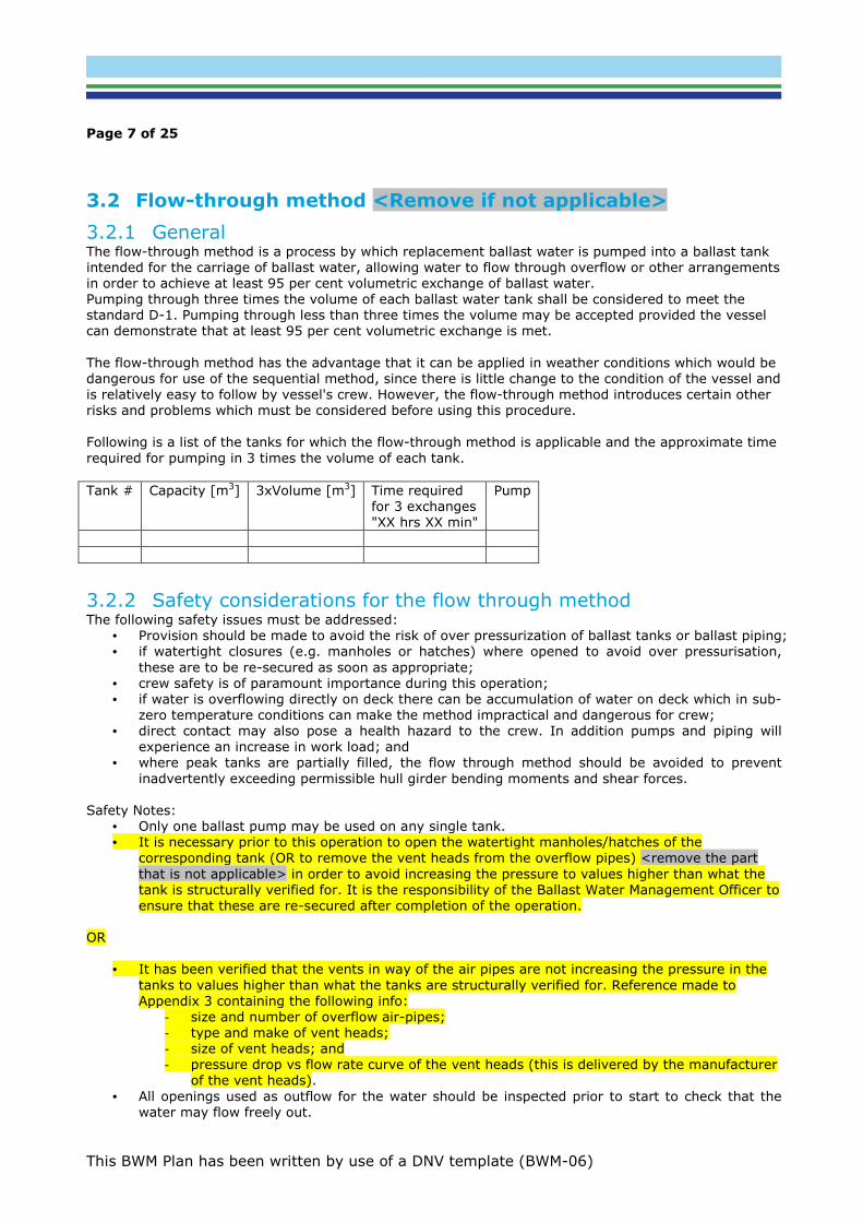
3.2 Flow-through method <Remove if not applicable>
3.2.1 General The flow-through method is a process by which replacement ballast water is pumped into a ballast tank
intended for the carriage of ballast water, allowing water to flow through overflow or other arrangements
in order to achieve at least 95 per cent volumetric exchange of ballast water.
Pumping through three times the volume of each ballast water tank shall be considered to meet the
standard D-1. Pumping through less than three times the volume may be accepted provided the vessel
can demonstrate that at least 95 per cent volumetric exchange is met.
The flow-through method has the advantage that it can be applied in weather conditions which would be
dangerous for use of the sequential method, since there is little change to the condition of the vessel and
is relatively easy to follow by vessel's crew. However, the flow-through method introduces certain other
risks and problems which must be considered before using this procedure.
Following is a list of the tanks for which the flow-through method is applicable and the approximate time
required for pumping in 3 times the volume of each tank.
Tank # Capacity [m3] 3xVolume [m3] Time required
for 3 exchanges
"XX hrs XX min"
Pump
3.2.2 Safety considerations for the flow through method The following safety issues must be addressed:
• Provision should be made to avoid the risk of over pressurization of ballast tanks or ballast piping;
• if watertight closures (e.g. manholes or hatches) where opened to avoid over pressurisation,
these are to be re-secured as soon as appropriate;
• crew safety is of paramount importance during this operation;
• if water is overflowing directly on deck there can be accumulation of water on deck which in sub-
zero temperature conditions can make the method impractical and dangerous for crew;
• direct contact may also pose a health hazard to the crew. In addition pumps and piping will
experience an increase in work load; and
• where peak tanks are partially filled, the flow through method should be avoided to prevent
inadvertently exceeding permissible hull girder bending moments and shear forces.
Safety Notes:
• Only one ballast pump may be used on any single tank.
• It is necessary prior to this operation to open the watertight manholes/hatches of the
corresponding tank (OR to remove the vent heads from the overflow pipes) <remove the part
that is not applicable> in order to avoid increasing the pressure to values higher than what the
tank is structurally verified for. It is the responsibility of the Ballast Water Management Officer to
ensure that these are re-secured after completion of the operation.
OR
• It has been verified that the vents in way of the air pipes are not increasing the pressure in the
tanks to values higher than what the tanks are structurally verified for. Reference made to
Appendix 3 containing the following info:
- size and number of overflow air-pipes;
- type and make of vent heads;
- size of vent heads; and
- pressure drop vs flow rate curve of the vent heads (this is delivered by the manufacturer
of the vent heads).
• All openings used as outflow for the water should be inspected prior to start to check that the
water may flow freely out.

Page 8 of 25
This BWM Plan has been written by use of a DNV template (BWM-06)
3.3 Dilution method <Remove if not applicable>
3.3.1 General The dilution method is a process by which replacement ballast water is filled through the top of the
ballast tank intended for the carriage of ballast water with simultaneous discharge from the bottom at
the same flow rate and maintaining a constant level in the tank through out the ballast exchange
operation.
Pumping through three times the volume of each ballast water tank shall be considered to meet the
standard D-1. Pumping through less than three times the volume may be accepted provided the vessel
can demonstrate that at least 95 per cent volumetric exchange is met.
xxx pump is connected to the top of the ballast tanks and xxx pump is connected to the bottom of the
ballast tanks.
The detailed procedure for connecting the pumps to the piping system in order to conduct ballast water
exchange using the dilution method is the following: xxx (spool pieces, valves to be opened/closed etc)
3.3.2 Safety considerations for Dilution Method Adequate provision should be made to avoid the risk of under or over pressurisation of ballast tanks and
ballast piping caused by blockages in air pipes or using excessive pumping rates relative to the design of
the ballast system.
The tank level shall be kept unchanged. <Add information on how to check that the ballast water level in
the tanks is constant for the vessel, instructions on how to handle cases where the water level increases
or decreases and provision of a manual emergency stop for any operating ballast pump in case of valve
malfunctioning or incorrect control actions shall be available and described in this paragraph>
4 BALLAST WATER TREATMENT <REMOVE IF NOT APPLICABLE>
4.1 Treatment system details
Manufacturers Name
Model Name
Technology
Operation required during <Ballasting, Deballasting, Circulation,
other>
TRC (Capacity) in m3/h 1)
Installation Location
Type Approval Certificate No.
TAC issued by
Number of ballast pumps to be used simultaneously 2)
one/two ballast pumps.
1) Range of flow rate from a minimum acceptable capacity up to the Treatment Rated Capacity acc. to
TAC.
2) Only one/two pumps can be used at a time for ballasting/de-ballasting, except in cases of
emergencies. <Include the approved number of pumps based on the approved ballast system drawing>

Page 9 of 25
This BWM Plan has been written by use of a DNV template (BWM-06)
Ballast water treatment system’s operation manual The system should only be operated in accordance with the system design criteria and manufacturer's
operational and maintenance instructions given in <name of specific operational and maintenance
manual of the BWMS and doc. number, approval reference number etc.>.
4.2 Control and monitoring equipment The control equipment automatically monitors and adjusts necessary dosages or intensities or other
aspects of the ballast water management system.
The control equipment should be able to store data for at least 24 months and should be able to display
or print a record for official inspections as required. In the event the control equipment is replaced,
means should be provided to ensure the data recorded prior to replacement remains available on board
for 24 months.
The control equipment of this treatment system consists of the following:
- Number of control panels with locations
- Integration to vessel automation system <Remove if not applicable>
- List of equipment located in hazardous area with reference to EX certificate if applicable
<Remove if not applicable>
4.3 Operation of the treatment equipment
4.3.1 Normal operating parameters This section includes simple and important parameters for the operation of the equipment, for example
<add important parameters such as pressure, flow rate, etc.)
4.3.2 Limitations of the system This section must include limitation for operating the equipment, for example
• minimum holding time in the tanks for systems using active substances
• minimum UV transmittance the system manages to treat
• salinity, temperature, pH etc.
• use of stripping ejector (i.e. treatment of driving water)
4.3.3 Ballasting operations This section must include vessel specific procedure for ballasting operation, such as
• before ballasting operations start (such as warm up sequence or internal circulation)
• for stopping ballasting operations
• detailed reference to the Operation Manual can be sufficient
4.3.4 De-ballasting operations This section must include vessel specific procedure for de-ballasting operation, such as:
• before de-ballasting operations start (such as warm up sequence or internal circulation)
•
• for stopping de-ballasting operations
• detailed reference to the Operation Manual can be sufficient
4.3.5 Shutdown of the treatment system This section must include procedure for shutdown. Detailed reference to the Operation Manual can be
sufficient

Page 10 of 25
This BWM Plan has been written by use of a DNV template (BWM-06)
4.3.6 By-pass The Convention requires the control system of the BWMS to trig an alarm and log any by-pass of the
BWMS. This include bypass due to gravity filling or discharge of tanks. <Remove if not applicable>
Treatment is not required for internal transfer, but such operations will be recorded. The system will
always trig the alarm in case of by-pass. Opening the following valves will give alarm and logging: < All by-pass valves subject to alarm and
logging are to be listed as approved>
- During ballasting
- During de-ballasting
Bypassing the treatment system during operation within one coastal zone is allowed. This will lead to
untreated water in the pipeline. Procedure to remove untreated water in pipeline is described in the
chapter below.
4.4 Handling of untreated ballast water
Untreated water in pipelines The ballast water pipeline may contain untreated water in case of e.g. bypass of the BWMS, common
pipeline for ballast water uptake and discharge or BWMS failure. To avoid discharge of untreated ballast
water, the following procedure will be carried out: <Fill in procedure>
Ballast water remaining in tanks <Applicable for systems approved by treatment on both ballasting
and de-ballasting, remove if not applicable> Ballast water remaining in the tanks after de-ballasting which has been treated only upon intake may
contain organisms that can reproduce in the ballast tanks potentially serving as a contamination source
for subsequent ballasting. To minimize the possibility of contamination it is important to empty the tanks
as much as possible.
<Fill in procedure i.e. stripping ejector>
4.5 Cleaning of combined ballast tanks <Remove if not applicable>
Tanks used for other purposes (e.g. mud / grey water / treated sewage) should be cleaned prior to using for holding ballast water that shall be treated. Otherwise the BWMS may not work properly. <Fill in
procedure> On this vessel this is relevant for:
- Tank <add tank #>
4.6 Procedure for OILREC mode <Remove if not applicable> <This section is applicable for vessels with OILREC notation and if any component of the BWMS is
installed in hazardous area and does not hold the applicable EX certificate>
This vessel has restricted operations when in OILREC mode. The vessel cannot perform ballasting
operations unless as allowed to by the BWM Convention in Article 3.2 or Regulation A-3, or under a
specific exemption from the flag accepted by the Party having jurisdiction over the waters in which the
vessel operates. In practice, the restriction means that the vessel can only operate in waters under the
jurisdiction of one Party when in OILREC mode. The BWMS is installed in <Add location of BWMS and hazardous zone>. When in OILREC mode the
BWMS is de-energized at all times. <Add instructions for disconnection of the BWMS>

Page 11 of 25
This BWM Plan has been written by use of a DNV template (BWM-06)
4.7 Safety and emergency procedures for the BWMS
The safety instructions as stated in the manufacturer’s Operation Manual are to be observed at all times.
The following Personal Protection Equipment (PPE) is provided in case of emergency:
PPE type Location Number
In the case of spillage or leakage of chemicals or gases, consult the procedures outlined in <insert
reference to emergency procedures in case of leakages in the manufacturer's manual>.
The following chemicals and/or gases are present during treatment either as by-products or as treatment
media: <Remove if not applicable>.
Chemical or gas Hazards
<Toxic, flammable, explosive>
4.8 Maintenance of the BWMS The maintenance schedule for the treatment system is as found in the manufacturers Operation Manual
are to be observed. <Add maintenance schedule for the vessel>

Page 12 of 25
This BWM Plan has been written by use of a DNV template (BWM-06)
5 PRECAUTIONARY PRACTICES
5.1 Minimising uptake or transfer of harmful aquatic organisms, pathogens and sediments
Wherever possible, ballast water should be taken outside of port waters and as far from the coast as
practicable. Consideration should also be given to the use of dockside water supplies (water not taken
directly from the harbour, such as fresh water, potable water etc.) as source for ballast water.
When loading ballast water, every effort should be made to avoid the uptake of potentially harmful
aquatic organisms, pathogens and sediments that may contain such organisms. The uptake of ballast
water should be minimized or, where practicable, avoided in areas and situations such as:
1. areas identified by the port state in connection with warnings provided by ports concerning ballast
uptake and any other port contingency arrangements in the event of emergency situations
2. in darkness when organisms may rise up in the water column
3. in very shallow water
4. where propellers may stir up sediment
5. areas with current large phytoplankton blooms (algal blooms such as red tides)
6. nearby sewage outfalls
7. where a tidal stream is known to be more turbid
8. where tidal flushing is known to be poor
9. in areas close to aquaculture
10. where dredging is or recently has been carried out.
If it is necessary to take on and discharge ballast water in the same location, care should be taken to
avoid unnecessary discharge of ballast water that has been taken up in another location.
5.2 Non-release/minimal release of ballast water The requirements to ballast water management differ from port state to port state. Some have no
requirements, some require reporting of ballast water practise and record book and others require
ballast water exchange before arrival in their waters. In case ballast water exchange is requested by the
port states, this will be applicable to ballast tanks planned to be discharged in their waters. For some
loading conditions not all tanks need to be discharged, hence these will not have to be exchanged prior
to arrival.
5.3 Discharge to reception facilities If reception facilities for ballast water and/or sediments are provided by a port state, they should, where
appropriate, be utilised.

Page 13 of 25
This BWM Plan has been written by use of a DNV template (BWM-06)
6 SEDIMENT MANAGEMENT Water taken up as vessels' ballast can contain solid alluvial matter that, once the water is becalmed in a
vessel’s ballast tank, will settle out onto the bottom of the tank and other internal structures.
Aquatic organisms can also settle out of the ballast water and can continue to exist within the sediment.
These organisms can survive for long periods after the water they were originally in has been discharged.
They may thereby be transported from their natural habitat and discharged in another port or area
where they may cause injury or damage to the environment, human health, property and resources.
6.1 General requirements All practical steps should be taken during ballast uptake to avoid sediment accumulation, it is however
recognised that sediment will be taken on board and settle on tank surfaces.
The volume of the sediment should be monitored on a regular basis.
Sediment in ballast tanks should be removed in a timely basis and as found necessary. The frequency
and timing of removal will depend on factors such as sediment build up, vessel’s trading pattern,
availability of reception facilities, work load of the vessel’s personnel and safety considerations.
6.2 Disposal of sediments to shore Removal of sediment from ballast tanks should preferably be undertaken under controlled conditions in
port, at a repair facility or in dry dock. The removed sediment should preferably be disposed of in a
sediment reception facility if available, reasonable and practicable.
One should be aware that sediments lying undisturbed for some time may give off toxic gases and
appropriate measures must be taken to protect the crew carrying out the job.
6.3 Disposal of sediments at sea When sediment is removed from the vessel’s ballast tanks and is to be disposed of by that vessel at sea,
such disposal should only take place in areas outside 200nm from land and in water depths of over 200m.
Part of the mud may be removed by water movement within a tank to bring sediments to suspension. In
double bottom tanks this is achieved by filling clean water 0.5-1 meter sounding in mild weather
conditions and keeping it for about 6 hours before pumping it out.
In addition the Master may decide to store the sediments onboard the vessel when this will not hamper
the security and operational maintenance of the vessel, her cargo and the crew. The sediments must
then be disposed of as described in 6.2 and above in this paragraph.
Special care is to be taken if ballast water has been carried in spaces designated for other purposes,
such as fuel, oil, fresh water tanks etc. Disposal of the sediments then depends upon the final mixture,
e.g. if ballast water is carried in the fuel tanks, more stringent requirements than described above are to
be considered.
6.4 Details of the sediment management system on board
<Remove if not applicable> The vessel is equipped with a special arrangement for disposal and handling of sediments.
< Insert details of the systems, including at least operational procedures for using it, frequency etc. as
well as reference to drawings of the system> - <Remove if not applicable>.
NOTE: Please be advised that until the BW Convention will be amended with specific requirements on
sediment handling the following procedures may be considered as sufficient: Manual cleaning of BW
tanks at dry-docking.

Page 14 of 25
This BWM Plan has been written by use of a DNV template (BWM-06)
7 BALLAST WATER SAMPLING Sampling of ballast water is primarily a matter for the authorised inspection officers during port state
control. For crew members there is unlikely any need to take samples except at the express request and
under the supervision of authorised inspection officers.
7.1 General The table below indicates sampling and access points in pipelines and tanks, to enable crew members to
quickly assist the authorised officers of a party that have reasons to obtain samples.
Tank #
Water sampling position
Type frame
distance
from CL position
Fore peak tank 227 9.2 Sounding pipe
WBT 1 PS 196 7.6 Main deck Manhole
AFT -14 0.2 Steering room Sounding pipe
Discharge line 37 8.9 Engine room Isokinetic sampling facility
For practical recommendations regarding sampling techniques and procedures, refer to Annex to
MEPC.173(58) – G2 Guidelines, addressing the following:
- Sampling from the ballast water discharge line
- Sampling from ballast water tanks <Remove if not applicable>
- Sampling and analysis protocols
- Sample data forms
- Health and safety aspects
- Recommendation for a port state control ballast water sampling kit
- Maintenance, storage, labelling and transportation
- Chain of custody record
7.2 Sampling for compliance with the exchange standard
(Regulation D-1) <Remove if not applicable> In-tank sampling may be appropriate for assessing compliance with ballast water exchange standard (D-
1).
Sampling the ballast water on arriving vessels may provide information on compliance with the ballast
water exchange standard by analysing their physical and/or chemical parameters. However, it is difficult
to use indicator (physical/chemical) parameters in isolation to conclusively prove that ballast water
exchange either has or has not occurred to the D-1 standard.
As with any analytical procedures or techniques used to test for compliance with the ballast water
exchange standard, methods used to test for compliance with ballast water exchange requirements
should be rigorously validated and widely distributed through the IMO.
For this vessel, sampling for compliance with the ballast water exchange standard is provided through
the following:
7.2.1 Sampling from the ballast water discharge line <Remove if not
applicable> The location of the sampling lines is given in the drawing in Appendix 1.
Reference is made to Part 1 of the Annex to MEPC.173(58) – G2 Guidelines for recommendations
regarding sampling techniques and procedures.

Page 15 of 25
This BWM Plan has been written by use of a DNV template (BWM-06)
7.2.2 Sampling from ballast water tanks Sampling from ballast water tanks for this vessel is done through:
- Manholes for ballast tanks <ballast water tanks reference>. Reference is made to Part 2 of
the Annex to MEPC.173(58) – G2 Guidelines for recommendations regarding sampling
techniques and procedures. <Remove if not applicable>
- Sounding pipes for ballast tanks <ballast water tanks reference>. Reference is made to Part
2 of the Annex to MEPC.173(58) – G2 Guidelines for recommendations regarding sampling
techniques and procedures. <Remove if not applicable>
- Air pipes for ballast tanks <ballast water tanks reference>. Reference is made to Part 2 of
the Annex to MEPC.173(58) – G2 Guidelines for recommendations regarding sampling
techniques and procedures. <Remove if not applicable>
The location of the sampling openings is given in the drawing in Appendix 1.
7.3 Sampling for compliance with the performance standard
(Regulation D-2) Compliance with ballast water performance standard (D-2) should be assessed at ballast water discharge,
as near to the point of discharge as practicable, during ballast water discharge whenever this is possible.
In-tank sampling to provide an indication of compliance with standard D-2 should only be used if ballast
water treatment process occurs on uptake, prior to or whilst ballast water is in the tank. If any part of
the treatment or neutralisation process is applied during the ballast water discharge, then in-tank
sampling is inappropriate.
For this vessel, sampling for compliance with the ballast water discharge standard is provided through
the following: <insert tank/pipe/sampling location>
7.3.1 Sampling from the ballast water discharge line <Remove if not
applicable>
The location of the sampling lines is given in the drawing in Appendix 1.
Reference is made to Part 1 of the Annex to MEPC.173(58) – G2 Guidelines for recommendations
regarding sampling techniques and procedures.
Page 16 of 25
This BWM Plan has been written by use of a DNV template (BWM-06)
8 METHODS OF COMMUNICATION This section contains procedures to assist the Master in coordinating the discharge of ballast in waters of
a coastal state, local government or other involved parties.
The quick and effective communication between the vessel and coastal state or other involved party
becomes vital in mitigating the effects of an unnecessary delay.
The requirements and roles of the various national and local authorities involved vary widely between
states and even from port to port. Approaches to the responsibility for ballast water exchange also vary.
In the majority of coastal states, responsibility for compliance with port state requirements is placed on
the vessel owner and the vessel.
The port state authorities should be contacted for specific ballast water discharge requirements and
reporting, prior to the vessel's arrival in port state's territorial waters.
Therefore, the Master with the responsible officer should timely obtain all necessary information and
prepare the vessel accordingly, taking into consideration the safety and operational restrictions as
described in this plan and relevant sections. Information on specific port state procedures can be
obtained by consulting the company and local agent for latest information and requirements.
8.1 Action to be taken by the vessel where coastal state has
specific procedures for discharge of ballast water
• follow agreed reporting procedures
• contact vessel's agent and/or company to ascertain latest information on ballast discharge
requirements in the water of respective state
• ensure to timely plan for above actions and that safety and operational restrictions are met
• keep proper records and have them readily available for possible inspection
8.2 Action to be taken by the vessel where coastal state has no specific procedures for discharge of ballast water
• contact vessel's agent and/or company to obtain latest information on ballast discharge
requirements in the water of respective state
• carry out discharge of ballast water as per the ballast exchange sequence
• take into consideration safety and operational procedures related to respective discharge
• keep proper records and have them readily available for possible inspection

Page 17 of 25
This BWM Plan has been written by use of a DNV template (BWM-06)
9 DUTIES OF THE BALLAST WATER MANAGEMENT OFFICER The ballast water management officer is responsible for implementing the procedures of the ballast
water management plan.
Duties of the ballast water management officer:
• ensure the safety of the vessel and crew
• ensure that ballast water management and/or treatment procedures are followed and
recorded
• where ballast exchange is required, ensure that the steps of the ballast exchange sequence
are followed in the prepared order
• ensure adequate personnel and equipment are available for the execution of the planned
ballast water management operations
• ensure all required ballast water management records are maintained and up to date,
including the ballast water record book
• where required, prepare the appropriate national or port ballast water declaration forms prior
to arrival
• assist the port state control or quarantine officers for any sampling that may need to be
taken
• undertake familiarisation and training of crew in ballast water management requirements and
applicable shipboard systems and procedures
• other duties, as specified by the company.
The Master must ensure that the ballast water management plan is clearly understood by the appointed
officer and by any other vessel staff that may need to be involved.
The ballast water management officer must keep the Master advised on the progress of the ballast water
management operations and any envisaged deviations from the agreed plan.
Should there be any doubt or if the management plan is not in line with the schedule, the Master shall be
advised accordingly.

Page 18 of 25
This BWM Plan has been written by use of a DNV template (BWM-06)
10 CREW TRAINING AND FAMILIARIZATION It is essential that the Master, vessel's officer and crew have an understanding of the need for ballast
water management.
If crew members understand the reasons for the treatment or exchange of ballast water and associated
sediments, they are more likely to ensure that it is carried out effectively and efficiently.
Owners, managers, operators and others involved in officer and crew training for ballast water
management should consider the following:
• training for vessels' Masters and crews as appropriate should include instructions on the
requirements of the Convention, the ballast water and sediment management procedures
and the ballast water record book, drawing particular attention to matters of vessel safety,
maintenance of records and reporting requirements in accordance with the Convention.
Vessels' officers and ratings engaged in ballast water exchange at sea must be aware of what is
expected of them and should be familiarised and trained in the following:
• vessel’s pumping arrangements including ballast arrangements;
• location of air and sounding pipes of all ballast tanks;
• positions of all ballast tank suctions and pipelines;
• overboard discharge arrangements and openings for release of water on deck;
• inspection and maintenance for ensuring that sounding pipes are clear and that air pipes and
non-return devices are in good order;
• times and circumstances required to undertake the various ballast water exchange
operations;
• methods used for ballast water exchange at sea, the related safety precautions and
associated hazards; and
• location and suitable access points for sampling purposes.
The Master and ballast water management officer should ensure that the personnel assigned key
responsibilities in any ballast exchange procedures are suitable and well trained according to the above.
Special attention should be given to the safety aspects related with the subject procedures.
Provisions for crew training and familiarisation include the following:
• general requirements for ballast water management;
• training and information on ballast water management practices;
• ballast water treatment systems installed on board;
• ballast water exchange methods;
• general safety considerations;
• the ballast water record book and maintenance of records;
• safety aspects associated with the particular systems and procedures used on board the
vessel which affect the safety or human health of crew and passengers and/or the safety of
the vessel;
• precautions for entering tanks for sediment removal;
• procedures for the safe handling and packaging of sediment; and
• storage of sediment

Page 19 of 25
This BWM Plan has been written by use of a DNV template (BWM-06)
11 RECORDING REQUIREMENTS
The ballast water management officer is to ensure that the Ballast Water Record Book and any other
necessary documentation and forms are kept up-to-date.
The Ballast Water Record Book may be an electronic record system or may be integrated into another
record book or system.
The Ballast Water Record Book entries shall be maintained on board the vessel for a minimum period of
two years after the last entry has been made.
The control equipment of the ballast water treatment system is able to store data for at least 24 months.
The requirements for type approval are that the control equipment should be able to display or print a
record for official inspections as required.
In the event the control equipment is replaced, means should be provided to ensure the data recorded
prior to replacement remains available on board for 24 months.
APPENDICES
Plans and Drawings
Appendix 1. Ballast tank arrangement & capacity plan.
Appendix 2. Ballast water piping & pumping arrangement, incl. air pipes and sounding arrangements.
Appendix 3. Plan & Profile of the vessel or schematic drawing of the ballast arrangement. <Remove if
not applicable>
Appendix 4. Diagrams/drawings of sampling and access points in pipelines and tanks <Remove if not
applicable>
Appendix 5: Vent heads (type, size, pressure drop vs. flow rate curves) as approved in Appendix 2<Applicable only if the flow through exchange method is used, remove otherwise> Appendix 6: Details of each step in the sequential exchange given in Section 2.2.4 above <Applicable only if the sequential exchange method is used, remove otherwise>