Ballantine 5500A Autometronic Counter Timer...
4
AuloMEIRONIC 70 MHz COUNTER-TIMER 5500A Programmable &Autoranging . .. . " M Hz 8 5 7 b " , e ..... 'M' '--I " FUNCTION, hL "uctJ "ul'; 4 (, II n J'ERIOO • IllIG I [" • nyC' IN' A.... U PERIOO • t!' * """"-fr, .. UP5t) rON' TU.IE TOIAl . un l ..... -Ofl POOG DISPLAY RESET TRIC SLOPE AllEN TIME LEVEL f:.::\ I ." - + 11 i'lO " 00 POWER OFF. , Ie '-- CHANNEL SEP COM CHK AllEN SLOPE TRIO LIVIL .. I -. r. DC .c LF IY. , ,",. 11- . .. 'C + J>50 . .IC B------/' :=;;.o"'-- CHANNEL A-------' AuioMEiRONIC COUNTER-TIMER MODEL 5500A o EASY TO USE - SELECTABLE RESOLUTION OF 4, 5, 6 OR 7 DIGITS o DEPENDABLE ACCURACY - CRYSTAL CLOCK - PROPORTIONAL OVEN o COMPACT HALF-RACK PACKAGE o SIMPLIFIED "HANDS-OFF" OPERATION The Ballantine 5500A Autometro nic Counter-Timer is a unique new development. Its display logic is based on resolution of readout - not on u ni ts of time averaging. The 5500A is ideal for au to mated test stands as well as general purpose use over a wi de ra nge of industrial and laboratory applications. The 5500A is t he first instrument to auto- range time interval measurements. The 5500A Autometronic contains a pa tcntedt autora ngi ng circuit that enables time an d frequency measurements to be made without the need for any operator adjust ments. The instrument automatically computes the dimensions of the measurement and position of the decimal point, and im- mediately displays the result on the numeric readout. The instrument is self-adjusting so that the most significant digit is in the left-most position. Range selection is concurrent with the measurement process. Frequency or time changes in the input signal are immediately displayed. o LOW COST - $650.00 o IDEAL FOR AUTOMATED MEASURE- MENTS - AUTORANGING IN ALL FREQUENCY AND TIMING MODES o SYSTEMS ORIENTED - REMOTELY PROGRAMMABLE All measurements except frequency ratios and the counting of total events are referenced to an internal time base. This time base is derived either from an oven-stabilized internally- generated \0 MHz crystal clock or from an external source. A rear-panel switch permits selection of the internal or ex- ternal clock. The main signal input to the instrument is supplied by the CHANN EL A BNC jack on the front panel. The operating mode and display resolution are selected by switches on the front panel. The 5500A may also be externally programmed by a single contact to ground or equivalent TIL/DTL compatible active circuit. Units and decimal points are in- ternally computed and displayed. Eight operating modes and six levels of resolution are remotely programmable. The 5500A has ten operating modes and a test mode. t Petent pending. BALLANTINE LABORATORIES, INC. FOUR DECADES OF INNOVATION IN ELECTRONIC INSTRUMENTATION
Transcript of Ballantine 5500A Autometronic Counter Timer...
AuloMEIRONIC 70 MHz COUNTER-TIMER
5500A
Programmable &Autoranging ... .
" MHz
8 57 b ", e (,~.....'M' ~,/ ~) '--I"
F UNCTION, hL "uctJ "ul';
4 (,IIn J'ERIOO • IllIG
I
[" • nyC' IN' ~\
A.... UPERIOO •
'REO*~ t!'* """"-fr, .. UP5t)
rON' TU.IE TOIAl
. unl.....-Ofl POOG
DISPLAY RESET TRIC SLOPE AllEN TIME LEVEL
f:.::\ I ."
- + 11 i'lO " 00
POWER OFF. i'~ . , Ie
'--CHANNEL
SEP COM CHK AllEN SLOPE TRIO LIVIL
.. I-. r. ~ DC
.c ~ LF
IY.
,,",. 11. .. 'C
+
J>50 . .IC
B------/' :=;;.o"'--CHANNEL A-------'
AuioMEiRONIC COUNTER-TIMER MODEL 5500A
o EASY TO USE - SELECTABLE RESOLUTION OF 4, 5, 6 OR 7 DIGITS
o DEPENDABLE ACCURACY - CRYSTAL CLOCK - PROPORTIONAL OVEN
o COMPACT HALF-RACK PACKAGE
o SIMPLIFIED "HANDS-OFF" OPERATION
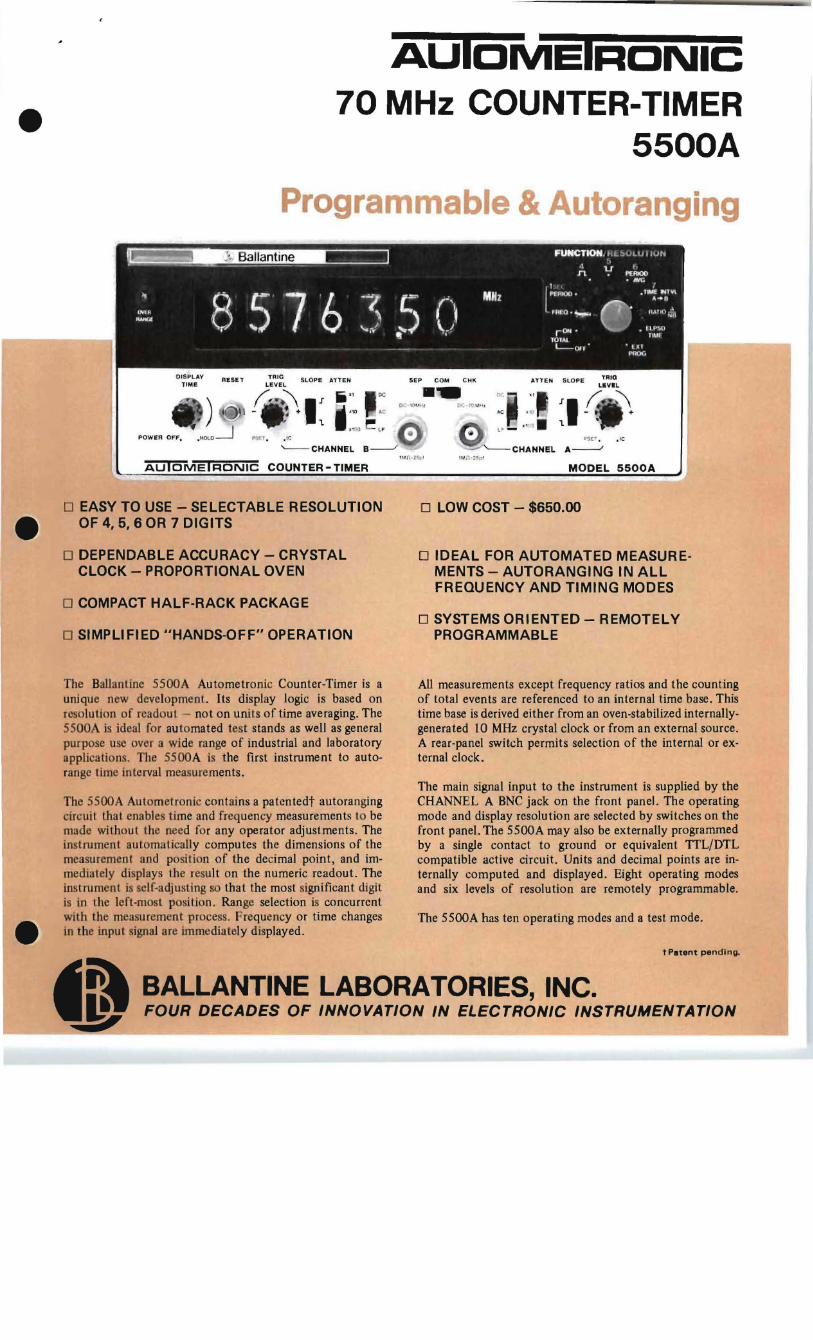
The Ballantine 5500A Autometro nic Counter-Timer is a unique new development. Its display logic is based on resolution of readout - not on units of time averaging. The 5500A is ideal for automated test stands as well as general purpose use over a wide range of industrial and laboratory applications. The 5500A is the first instrument to autorange time interval measurements.
The 5500A Autometronic contains a pa tcntedt autoranging circuit that enables time and frequency measurements to be made without the need for any operator adjust ments. The instrument automatically computes the dimensions of the measurement and position of the decimal point, and immediately displays the result on the numeric readout. The instrument is self-adjusting so that the most significant digit is in the left-most posit ion. Range selection is concurrent with the measurement process. Frequency or time changes in the input signal are immediately displayed.
o LOW COST - $650.00
o IDEAL FOR AUTOMATED MEASUREMENTS - AUTORANGING IN ALL FREQUENCY AND TIMING MODES
o SYSTEMS ORIENTED - REMOTELY PROGRAMMABLE
All measurements except frequency ratios and the counting of total events are referenced to an internal time base. This time base is derived either from an oven-stabilized internallygenerated \0 MHz crystal clock or from an external source. A rear-panel switch permits selection of the internal or external clock.
The main signal input to the instrument is supplied by the CHANN EL A BNC jack on the front panel. The operating mode and display resolution are selected by switches on the front panel. The 5500A may also be externally programmed by a single contact to ground or equivalent TIL/DTL compatible active circuit. Units and decimal points are internally computed and displayed. Eight operating modes and six levels of resolution are remotely programmable.
The 5500A has ten operating modes and a test mode.
t Petent pending.
BALLANTINE LABORATORIES, INC. FOUR DECADES OF INNOVATION IN ELECTRONIC INSTRUMENTATION
5500A AuloMEIRONIC COUNTER-TIMER COUNT
Frequency: 0-70 MHz. Counter Range: 1 to 107 counts. Input: Channel A. Gate Time: Manually selected. Accuracy: Absolute. Readout: Dimensionless.
FREQUENCY
Range: 0-70 MHz. Input: Channel A. Gate Time: Automatically selected to fill the display (up to 1 sec),
or 1 sec manual. The number of digits displayed can be selected as 4, 5, 6 or 7 by a front-panel switch.
Accuracy: ± I count ± time-base accuracy. Readout: kHz or MHz, with automatically positioned decimal
point.
PERIOD
Range: 100 nsec to 107 seconds. Input: Channel A. Clock Frequency: 100 nsec to I second i.n decimal steps, auto
matically selected to fill the display. The number of digits displayed can be selected as 4, 5, 6 or 7 by a front-panel switch.
Resolution: O.ll.Isec to 1 sec, automatically selected for maximum resolution.
Accuracy: ±I count ± time-base accuracy ± trigger error*. Readout: l.Isec, msec or sec, with automatically positioned decimal
point.
POSITIVE OR NEGATIVE PULSE WIDTH
Range: 0.1 l.Isec to 107 sec. Input: Channel A. Clock Frequency: 100 nsec to I second in decimal steps, auto
matically selected to fill the display. The number of digits displayed can be selected as 4, 5,6 or 7 by a front-panel switch.
Slope Selection: Automatically selected. Resolution: O.ll.Isec to I sec, automatically selected for maximum
resolution. Accuracy: ± I count ± time-base accuracy ± trigger error*. Readout: I.Jsec, msec or sec, with automatically positioned decimal
point.
PERIOD AVERAGE
Range: 100 Hz to I MHz, 4-digit resolution. 10 Hz to I MHz, 5-digit resolution.
1 Hz to 1 MHz, 6-digit resolution. 0.1 Hz to I MHz, 7-digit resolution.
Input: Channel A. Periods Averaged: I to 1000, automatically selected for maximum
resolution. Clock Frequency: 1 MHz. Accuracy: ± I count ± time-base accuracy ± trigger error*. Readout: l.Isec, with automatically positioned decimal point.
TlMEA .. B
Range: 0.1 JJsec to 107 sec. Input: Start Signal: Channel A. Stop Signal: Channel B.
Can be common or separate. Clock Frequency: 100 nsec to I second in decimal steps, auto
matically selected to fill the display. The number of digits displayed can be selected as 4, 5, 6 or 7 by a front-panel switch.
Resolution: O.ll.Isec to I sec, automatically selected for maximum resolution.
Accuracy: ±I count ± time-base accuracy ± trigger error of A* ± Trigger error of B*.
Readout: JJsec, msec or sec, with automatically positioned decimal point.
RATIO AlNB
Range: Channel A: 0-70 MHz. Channel B: 0-10 MHz. Input (Fl): Channel A. Input (F2): Channel B. Measures: fol/F2. Number of Cycles of F2 Averaged: I to 1000 automatically selected
for maximum resolution. Accuracy: ±I count of FI ± trigger error of F2*. Readout: Dimensionless, with automatically positioned decimal
point.
TIME INTVL
Range: 0.1 JJsec to 107 sec. Clock Frequency: 100 nsec to 1 second in decimal steps, auto
matically selected to fill the display. The number of digits displayed can be selected as 4, 5,6 or 7 by a front-panel switch.
Gate Signal: Via rear panel connector. Contact closure to ground or saturated transistor will control the gate time.
Resolution: O.ll.Isec to I sec, automatically selected for maximum resolution.
Accuracy: ± I count ± time-base accuracy ± gate error. * * Readout: /.lSec, rilsec or sec, with automatically positioned
decimal point.
INPUT CHANNELS A AND B
Range: Channel A, DC coupled: DC-70 MHz AC coupled : 20 Hz-70 MHz HF Rejection: Attenuates signals above
I kHz approx. Channel B,
DC coupled: DC-IO MHz AC coupled: 20 Hz-IO MHz HF Rejection: Attenuates signals above
I kHz approx . Impedance: I megohm shunted by 25 pF approx. Sensitivity: 25 mV rms sine wave 0-2 MHz.
50 mV rms sine wave 2-10 MHz. 100 mV rms sine wave 10-70 MHz (channel A only).
Channel A, 0.3 V peak-to-peak pulse, 7 nsec min pulse width. Channel B, 0.3 V peak-to-peak pulse, 50 nsec min pulse width.
Preset: Sets trigger reference to 0 volts. Attenuation: XI, XIO, XI00. Trigger Level: Continuously adjustable ±l V, ±10 V, ±100 V,
dependent upon setting of attenuator. Slope: Independent selection of positive or negative slope. Overload Protection: 250 V rms on XI 0 and XlOO attenuator set
tings, 120 V rms on XI attenuator setting up to I kHz, decreasing to 10 V rms above 10 MHz.
Shaped Outputs A and B: Terminals on the rear panel for external monitoring of the triggering points on the input signals.
DISPLAY
Numerical: 6 digits (7 optional). Units: kHz, MHz, JJsec, msec or sec, automatically computed and
displayed. Decimal Point: Automatically selected. Display Storage: Prior reading is held while new reading is being
made. Display time is adjustable from 0.2 to 5 seconds or held indefinitely.
Gate: Lights up when counter gate is open. Overrange: Solid-state indicator that lights up when the counter
capacity is exceeded. Due to the automatic gate selection, the counter capacity can be exceeded only when using the manually selected I sec gate time in Frequency mode or in the Period Average and Ratio modes.
Manual Reset: Front-panel pushbu t10n switch resets the display and all registers, and initiates a new measurement.
TIME BASE
Crystal Frequency: 10 MHz Crystal Oven: Self-regulating solid-state proportional oven.

Aging Rate: Less than 2 parts in 108 per day after 10 days of continuous operation. Ocss than 0.02 ppm per day)
Temperature Stability: Less than 2 parts in 10 6 from OOC to +50°C. (Normally less than 0.04 ppm per °C)
Line Voltage Stability: Less than 5 parts in 107 for ±IO% line voltage change. (Nominally less than 0.05 ppm per % change)
Ext. Time Base Input: Via rear panel BNC connector, I kHz to 10 MHz, 0 .5 V rms into I Kohm.
Iht. Time Base Output: I MHz via rear panel BNC connector.
GENERAL Display: 6 gas discharge type numeric indicators (7 optional) Operating Temperature: O°C (+32°F) to +50oC (+1 22°F). Power Requirements: 115 or 230 volts ±IO%, 48 to 400 Hz, 25 watts.
25 watts. Dimensions: 3 1/2" (88 mm) H x 8 3/8" (212 mm) W x 12 1/2"
(316mm)D. Weight: 7 pounds (3.2 Kg). Accessories Furnished: Power cord, Service Manual. Price: $650.00 fob Boonton, N.J .
ACCESSORIES AVAILABLE Description Part No. Price
Probe Kit - Attenuator 10: I /1: 16ft. 10601 A $32.00 50 ohm 4 ft BNC-to·BNC coaxial cable 122490 7.50 Display EXlender Board 89400001 A 12.00 6 ft cable to connect Ihe 5500A 10 a
digital recorder 12253A 60.00 6 ft cable to connect the 5500A for
remote programming 12254A 50.00 Feed thru Termination, 50 n BNC I 2630A 12.50 50 n4 ft BNC to alligator cable 12250D 8.50
OPTIONS AVAILABLE Description Price
7-DIGIT DISPLA Y (Option No. 07) $35.00 PRINTER OUTPUT (Option No. 10) 75.00
Logic: Positive true Form: 4·line 1-2-4-8 BCD.
"I"statelevel: +5±0.5 V, 2.5 Kohm source impedance nominal. "0" state level: + 0.25 Vat -I rnA.
Print Command: Positive pulse of 5 V, DC coupled. Source impedance is 5 Kohm when in the "high" state and 500 ohm when in Ihe "low" state . Pulse duration is I msec approx. Occurs at end of gate time.
Inhibit Input: A positive pulse of 3 V minimum and 50 V maxi· mum will inhibit the recycling circuitry of the counter.
Connector: Amphenol 57 -40500-37 5 (50-pin blue ribbon). Mating connector AmphenoI57-30500 - 375. P/N 31 100500A $12.50
REMOTE PROGRAMMING (Option No. 02) $75.00 Permits function and resolution to be remotely selected by a singlc contact to ground or equivalent active circuit. (TTL & DTL compatible) The time base is automatically selected for maximum resolution. Mating connector (24-pin Blue Ribbon) Amphenol 57·30240-375, P/N 31100370A $12.50
• Trigger error is less than 0.3% of one period divided bV the number of periods averaged. for signals with 8 signal·to-nolse ratio of 40 db or better. and 100 mV rms amplituda.
•• For any waveshape, trigger error is less than
____0_.0_0_2_5____ Microseconds.
±Signal slope (Volts/J../s1
MODES OF OPERATION
COUNT MODE
In the COUNT mode, the 5500A operates as a simple total events counter. The input to the counting circuits is the signal applied to the CHANNEL A jack. ON·OFF gating is controlled manually by a front-panel switch.
FREQUENCY MODE FREQUENCY mode provides direct measurement of the average frequency of any signal from 0 to 70 MHz . The input signal to the counting circuits is applied to the CHANNEL A jack. Input trigger circuits are DC or AC coupled . Trigger leveling and 3 ranges of attenuation are provided as well as a low pass filter for noisy input signals. The display resolution is maximized by au toma tic selection of the gate time.
PERIOD MODE PERIOD mode provides direct measurement of a single period of an input signal. The input to the counting circuits is the automatically·selected time·base frequency. The time interval over which counting is enabled is the period of the signal applied to CHANNEL A. Display resolution is automatically maximized with best resolution of 100 nano· seconds.
POSITIVE PULSE WIDTH MODE POSITIVE PULSE WIDTH mode provides direct measurement of the time between the leading and trailing edges of a pulse . The inpu t to the counting circuits is the au tomatically selected time·base frequency. The time interval over which counting is enabled is the time between the leading and trailing edges of the signal applied to CHANNEL A.
NEGATIVE PULSE WIDTH MODE NEGATIVE PULSE WIDTH mode provides direct measurement of the time between the trailing and leading edges of a pulse. The input to the counting circuits is the automatically selected time·base frequency. The time interval o'.rer which counting is enabled is the time between the trailing and leading edges of the signal applied to the CHANNEL A jack.
PERIOD AVERAGE MODE PERIOD AVERAGE mode provides direct measurement of the average period of an input signal. The number of periods averaged is automatically variable from I to 103 in decade steps. The time interval over which counting is enabled is the average period of the signal applied to CHANNEL A. The input to the counting circuits is a I MHz signal derived from the 10 MHz clock .
RATIO A/NB MODE RATIO A/NB mode provides measurement of the frequency ratio of two input signals. Signal B is automatically averaged over from I to 103 cycles . The signals may be applied to either of the input jacks.
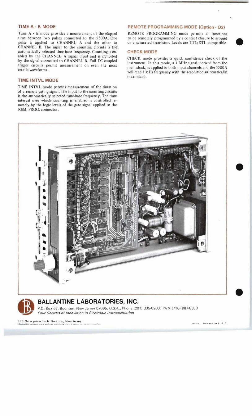
TIME A .. B MODE REMOTE PROGRAMMING MODE (Option - 02) Time A .. B mode provides a measurement of the elapsed time between two pulses connected to the 5500A. One pulse is applied to CHANNEL A and the other to CHANNEL B. The input to the counting circuits is the automatically selected time-base frequency. Counting is enabled by the CHANNEL A signal input and is inhibited by the signal connected to CHANNEL B. Full DC coupled trigger circuits permit measurement on even the most erratic waveforms.
TIME INTVL MODE TIME INTVL mode permits measurement of the duration of a remote gating signal. The input to the counting circuits is the au tomatically selected time-base frequency. The time interval over which counting is enabled is co ntrolled remotely by the logic levels of the gate signal applied to the REM. PROG. connector.
REMOTE PROGRAMMING mode permits all functions to be remotely programmed by a contact closure to ground or a sa tura ted transistor. Levels are TTL/DTL compa tible.
CHECK MODE
CHECK mode provides a quick confidence check of the instrument. In this mode, a I MHz signal, derived from the main clock, is applied to both input channels and the 5500A will read I MHz frequency with the resolution automatically maximized.
,1) 1, }
.
-~~WD' BALLANTINE LABORATORIES, INC.
P.o. Box 97 , Boonton, New Jersey 07005, USA., Phone (201) 335·0900, TWX (710) 987·8380 ~ Four Decades of Innovation in Elec tronic Instrumentation
U .S . Sales prices f.o .b . Boonton, New Jersey . 0 .. : ......... -1 : .... II C' 1\